ROC TC Initial Ballot Cover Memo - NFPA A11 ROC... · generated from a Flexographic printing...
33
National Fire Protection Association 1 Batterymarch Park, Quincy, MA 02169-7471 Phone: 617-770-3000 • Fax: 617-770-0700 • www.nfpa.org M E M O R A N D U M TO: NFPA Technical Committee on National Fuel Gas Code FROM: Joanne Goyette DATE: November 15, 2010 SUBJECT: NFPA 54 ROC TC Letter Ballot (A2011) ______________________________________________________________________ The ROC letter ballot for NFPA 54 is attached. The ballot is for formally voting on whether or not you concur with the committee’s actions on the comments. Reasons must accompany all negative and abstention ballots. Please do not vote negatively because of editorial errors. However, please bring such errors to my attention for action. Please complete and return your ballot as soon as possible but no later than November 29, 2010. As noted on the ballot form, please return the ballot to Joanne Goyette either via e-mail to [email protected] or via fax to 617-984-7110. You may also mail your ballot to the attention of Joanne Goyette at NFPA, 1 Batterymarch Park, Quincy, MA 02169. The return of ballots is required by the Regulations Governing Committee Projects. Attachments: Comments Letter Ballot
Transcript of ROC TC Initial Ballot Cover Memo - NFPA A11 ROC... · generated from a Flexographic printing...

National Fire Protection Association 1 Batterymarch Park, Quincy, MA 02169-7471 Phone: 617-770-3000 • Fax: 617-770-0700 • www.nfpa.org
M E M O R A N D U M TO: NFPA Technical Committee on National Fuel Gas Code FROM: Joanne Goyette DATE: November 15, 2010 SUBJECT: NFPA 54 ROC TC Letter Ballot (A2011)
______________________________________________________________________ The ROC letter ballot for NFPA 54 is attached. The ballot is for formally voting on whether or not you concur with the committee’s actions on the comments. Reasons must accompany all negative and abstention ballots. Please do not vote negatively because of editorial errors. However, please bring such errors to my attention for action. Please complete and return your ballot as soon as possible but no later than November 29, 2010. As noted on the ballot form, please return the ballot to Joanne Goyette either via e-mail to [email protected] or via fax to 617-984-7110. You may also mail your ballot to the attention of Joanne Goyette at NFPA, 1 Batterymarch Park, Quincy, MA 02169. The return of ballots is required by the Regulations Governing Committee Projects. Attachments: Comments Letter Ballot

Report on Comments – June 2011 NFPA 54_______________________________________________________________________________________________54-1 Log #4
_______________________________________________________________________________________________John F. Bender, Underwriters Laboratories Inc.
54-6Revise text to read as follows:
Underwriters Laboratories Inc., 333 Pfingsten Road, Northbrook, IL 60062-2096, www.ul.com.ANSI/UL 651, Schedule 40 and 80 Rigid PVC Conduit and Fittings, 2005, Revised 2008 2010.
Reason: Update referenced standards to most recent revisions.
_______________________________________________________________________________________________54-2 Log #23
_______________________________________________________________________________________________Glossary of Terms Technical Advisory Committee ,
54-9Extract the definition of Readily Accessible from NFPA 70, National Electrical Code.
Capable of being reached quickly for operation, renewal, or inspections, without requiringthose to whom ready access is requisite to climb over or remove obstacles or to resort to portable ladders, and so forth.[70, 2008]
The definition of Readily Accessible currently in NFPA 54 is not specific to fuel gas. The definition inNFPA 70 is similar and is the preferred definition according to the Glossary of Terms.
The definition published in NFPA 70, , is specific to access to switchgear, panel boards, etc., and is therefore not appropriate for fuel gas installations. The existing definition in NFPA 54 ismore appropriate for fuel gas installations. The NFPA 54 definition is an accepted definition in the NFPA Glossary ofTerms, and the TC reaffirms the unique definition.
_______________________________________________________________________________________________54-3 Log #24
_______________________________________________________________________________________________Glossary of Terms Technical Advisory Committee ,
54-13Remove the definition of Btu from Chapter 3.
Commonly used abbreviations do not need to be defined within Chapter 3. This complies with themanual of style and the Glossary of Terms project.
The committee rejected the comment because, while BTU is a commonly used term byengineers, it is not always understood by other users of the Code.
1Printed on 11/15/2010

Report on Comments – June 2011 NFPA 54_______________________________________________________________________________________________54-4 Log #25
_______________________________________________________________________________________________Glossary of Terms Technical Advisory Committee ,
54-17Adopt the preferred definition of Combustion as found in NFPA 5000.
A chemical process of oxidation that occurs at a rate fast enough to produce heat and usuallylight in the form of either a glow or flame.[5000, 2009]
The preferred definition is used in most NFPA documents, including NFPA 1, 53, 101, 211, and 5000.The Glossary of Terms Technical Advisory Committee recommends NFPA 54 reconsider proposal 54-17 unless thepreferred definition does not meet the committee’s needs.
_______________________________________________________________________________________________54-5 Log #CC13
_______________________________________________________________________________________________Technical Committee on National Fuel Gas Code,
54-53Revise text to read as follows:
3.3.88.1 Gas Appliance Pressure Regulator. A pressure regulator for controlling pressure to the appliance manifold.3.3.88.3 Line Pressure Gas Regulator. A pressure regulator placed in a gas line between the service regulator and the
appliance regulator.5.8.1 Where Required. A line gas pressure regulator or gas appliance pressure regulator, as applicable, shall be
installed where the gas supplypressure is higher than that at which the branch supply line or appliances are designed to operate or vary beyonddesign pressure limits.5.8.2 Listing. Line gas pressure regulators shall be listed in accordance with ANSI Z21.80/CSA 6.22, Line Pressure
Regulators.5.8.5.1 Line Gas Pressure Regulators. Line gas pressure regulators shall comply with the following:5.8.5.2 Gas Appliance Pressure Regulators. For venting of gas appliance pressure regulators, see 9.1.19.NOTE: Update terminology throughout the standard to be consistent with revised definitions.
The TC revised the definition and terminology to be consistent with Z21.80 and Z21.18.
2Printed on 11/15/2010

Report on Comments – June 2011 NFPA 54_______________________________________________________________________________________________54-6 Log #3
_______________________________________________________________________________________________Mindy Wang, Ampco Safety Tools
54-42Revised original proposal to read as follows:
(2) Smoking, open flames, lanterns, welding, ferrous tools or other sources of ignition shall not be permitted.· FM Approvals LLC, formerly Factory Mutual Research Corporation, (FM) is an international
organization recognized by the U.S. government as a Nationally Recognized Testing Laboratory (NRTL) for scientificresearch and product certification. Product approval from a NRTL assures that products meet consensus-basedstandards of safety to provide the assurance, required by OSHA, that these products are safe for use in the UnitedStates workplace. FM Approval Standard 7910, Spark Resistant Tools is used as guidance to evaluate tools intendedfor use in environments where there is a risk of ignition of flammable materials, dusts or vapors resulting from sparkscreated by iron and steel hand tools. These tools prevent the ignition of flammable materials, dusts or vapors bymechanical sparks created by the use of iron and steel hand tools slipping or striking a surface. These tools provide asolution in place of ferrous tools in flammable environments.· OSHA inspection# 2272953, two employees were assigned the job of tending a 100 gallon (water jacket)
reactor kettle of methyl methacrylate in the mixing room. Employee #1 used a metal wrench (visegrips) to pry open thecover of a kettle. The wrench handle struck the angle iron support for the agitator motor, producing a spark. Employee#2 noticed the spark, which was immediately followed by a massive “fire ball”. Clearly, spark created from metal onmetal ignited the flammables. Furthermore, the investigation states that non-sparking tools were not provided for theemployees.· In an accident reported by the Seattle Times, a fire gutted a garage and home. The deputy fire marshal stated
that a spark from a dropped metal tool ignited spilled gasoline on the floor when a man working on his car in the garage.· OSHA inspection# 124384835, employee #1 and coworkers were draining fluids and sand from the sand
catcher tank on a natural gas well that had 3,000 psi head pressure. As the sand catcher tank emptied, gas rushed outthe drain line, raising the end of the unsecured line. A fitting failed, and the line blew apart. Metal striking metal thenignited an explosion and fire in which Employee #1 was killed.· OSHA inspection# 300965795, employee #1 was in the process of cleaning loose material from drill piping with
a metal hammer. While striking the pipe with a hammer, an explosion occurred. Employee #1 was killed.· OSHA inspection#119775823, employee #1 was working on a solvent recovery system to recycle solvent
generated from a Flexographic printing process. As the spent solvent was poured into the system, sludge started to riseand a cloud of white smoke began to form. In closing the machine, the lid hit against the metal surface and generated aspark that ignited the solvent vapors. Employee #1's sustained second-degree burns to his upper right arm and wastaken to the hospital.· NFPA 54, Annex E Suggested Emergency Procedure for Gas Leaks, paragraph (2) “Use every practical means
to eliminate sources of ignition. Take precautions to prevent smoking, striking matches, operating electrical switches ordevices, opening furnace doors, and so on.” This sample of documented events illustrates accidents do happen whenproper safety measures are not taken to eliminate ignition sources. A practical mean to control mechanical sparks fromferrous tools is to use spark resistant tools in flammable atmospheres.We respectfully request the Committee to reconsider and take action to implement safer practices. Without this
specification, ferrous tools are likely to be used which can be an ignition source. However, if upon further consideration,the Committee still does not see the need to include spark resistant tools, we ask the Committee to at least includeproposed text in the annex text of NFPA 54 to raise the awareness of ignition hazard associated with steel or ferroustools in direct contact with flammable materials and the proposed text will read Annex A, A.4.3.1 (2) Ferrous tools shouldnot be used within classified areas.
The use of ferrous tools has not been shown to provide a definitive source of ignition. Inaddition, 4.3.1(3) states a flammable gas-air mixture shall not be present when the use of tools (such as welding orcutting torches or other tools that may provide a source of ignition) is necessary.
3Printed on 11/15/2010

Report on Comments – June 2011 NFPA 54_______________________________________________________________________________________________54-7 Log #28
_______________________________________________________________________________________________Peter Baker, Maxitrol Company
N/ARevise text to read as follows:
Materials used for piping systems shall comply with the requirements of this chapter orshall be acceptable to the authority having jurisdiction.
Shall be listed and may be manufactured of aluminum canbe used provided that the control is equipped with female threads and are of the Tapered NPT type. Filters andStrainers made of aluminum may also be used and are subject to the same thread requirements as controls.
Pipe, fittings, valves, or other materials shall not be used again unless they are free offoreign materials and have been ascertained to be adequate for the service intended.
Metallic fittings shall comply with the following:(1) Threaded fittings in sizes larger than 4 in. (100 mm) shall not be used unless acceptable to the authority having
jurisdiction.(2) Fittings used with steel or wrought-iron pipe shall be steel, brass, bronze, malleable iron, or cast iron.(3) Fittings used with copper or brass pipe shall be copper, brass, or bronze.(4) Fittings used with aluminum alloy pipe shall be of aluminum alloy.(5) Cast-iron fittings shall comply with the following:
(a) Flanges shall be permitted.(b) Bushings shall not be used.(c) Fittings shall not be used in systems containing flammable gas–air mixtures.(d) Fittings in sizes 4 in. (100 mm) and larger shall not be used indoors unless approved by the authority having
jurisdiction.(e) Fittings in sizes 6 in. (150 mm) and larger shall not be used unless approved by the authority having jurisdiction.
(6) Threads shall not form the joint seal(7) Fittings shall not be used in systems containing flammable gas–air mixtures.(8) Fittings such as couplings, proprietary-type joints, saddle tees, gland-type compression fittings,
and flared, flareless, or compression-type tubing fittings shall be as follows:(a) Used within the fitting manufacturer’s pressure–temperature recommendations(b) Used within the service conditions anticipated with respect to vibration, fatigue, thermal expansion, or contraction(c) Installed or braced to prevent separation of the joint by gas pressure or external physical damage(d) Acceptable to the authority having jurisdiction
The current wording in NFPA 54 does not adequately address the differences between fittings andcontrol devices. Controls are clearly defined in NFPA 54 but the current wording drags controls under the umbrella offittings. We believe the original intent was not to prohibit cast aluminum bodies for controls rather to prohibit the use ofcast fittings such as couplings and elbows. The industry has been using cast aluminum bodies for regulators and controlvalves for many years without issue. All of the ANSI standards that these products are certified too require a minimumdistance to shoulder requirement that eliminates the potential for the steel pipe to interfere with the performance of thecontrol device.
The proposed controls section 5.6.1.2 is new material that has not had the benefit of publicreview. Section 5.6.1 is not the appropriate location for a controls requirement. In addition, the submitter has notprovided any substantiation to support a requirement for listing of all controls, which is a new concept for the Code.Refer to 54-9 (Log #7) for action on 5.6.8.4.
4Printed on 11/15/2010

Report on Comments – June 2011 NFPA 54_______________________________________________________________________________________________54-8 Log #19
_______________________________________________________________________________________________Frank R. Volgstadt, Volgstadt and Associates
54-5Revise text to read as follows:
5.6.4.1 Standard and Marking. Plastic pipe, tubing, and fittings used to supply fuel gas shall conform to ASTM D 2513,Standard Specification for Polyethylene (PE) Thermoplastic Gas Pressure Pipe, Tubing, and Fittings. Pipe to be usedshall be marked "gas" and "ASTM D 2513."
D2513-09a is revised to be a PE only standard with the revised title as shown above.
Revise text to read as follows:5.6.4.1 Standard and Marking. Polyethylene Pplastic pipe, tubing, and fittings used to supply fuel gas shall conform to
ASTM D 2513, Standard Specification for Polyethylene (PE) Thermoplastic Gas Pressure Pipe, Tubing, and Fittings.Pipe to be used shall be marked "gas" and "ASTM D 2513."5.6.4.2 Plastic pipe, tubing and fittings, other than polyethylene, shall be identified in and conform to the 2008 edition of
ASTM D 2513, Standard Specification for Thermoplastic Gas Pressure Pipe, Tubing, and Fittings. Pipe to be used shallbe marked "gas" and "ASTM D 2513".(Correct the title of ASTM 2513 throughout the document.)
The TC recognized that the scope of the ASTM standard has changed and is now limited topolyethylene pipe, tubing and fittings. The submitter did not provide any substantiation indicating that otherthermoplastic materials should be disallowed in NFPA 54. However, the TC determined that the change in the scope ofASTM 2513 would inadvertently prohibit the use of these other materials in NFPA 54 installations. Therefore the TCadded a reference to the previous edition to continue to allow the use of other types of thermoplastic pipe, tubing, andfittings.
5Printed on 11/15/2010
Report on Comments – June 2011 NFPA 54_______________________________________________________________________________________________54-9 Log #7
_______________________________________________________________________________________________Ted Jablkowski, Fives North American Combustion, Inc.
54-50
Metallic fittings shall comply with the following:(1) Threaded fittings in sizes larger than 4 in. (100 mm) shall not be used unless acceptable to the authority having
jurisdiction.(2) Fittings used with steel or wrought-iron pipe shall be steel, brass, bronze, malleable iron, or cast iron.(3) Fittings used with copper or brass pipe shall be copper, brass, or bronze.(4) Fittings used with aluminum alloy pipe shall be of aluminum alloy.(5) Cast-iron fittings shall comply with the following:(a) Flanges shall be permitted.(b) Bushings shall not be used.(c) Fittings shall not be used in systems containing flammable gas–air mixtures.(d) Fittings in sizes 4 in. (100 mm) and larger shall not be used indoors unless approved by the authority having
jurisdiction.(e) Fittings in sizes 6 in. (150 mm) and larger shall not be used unless approved by the authority having jurisdiction.(6) Threads shall not form the joint seal.(7) Fittings shall not be used in systems containing flammable gas–air mixtures.(8) Fittings such as couplings, proprietary-type joints, saddle tees, gland-type compression fittings,
and flared, flareless, or compression-type tubing fittings shall be as follows:(a) Used within the fitting manufacturer's pressure–temperature recommendations(b) Used within the service conditions anticipated with respect to vibration, fatigue, thermal expansion, or contraction(c) Installed or braced to prevent separation of the joint by gas pressure or external physical damage(d) Acceptable to the authority having jurisdiction
The use of “ . in 5.6.8.4 is in conflict with the requirements ofin terms of including devices, like valves, strainers and filters with pipe
fittings (e.g. elbows, tees and couplings). are implied in 5.6.8 which is the substantiation for addingin 5.6.8.4.
The substantiation for deleting (Including Valves, Strainers, Filters) is from
Pipe Fittings or Fittings is not defined in NFPA 54, which means that the generally accepted definition is used withinthe Code.
Additional substantiation to support deleting (Including Valves, Strainers, Filters) is that valves are control devices andare defined along with special controls in:
Devices designed to regulate the gas, air, water, or electrical supply to an appliance. These may bemanual or automatic. A device responsive to changes in pressure, temperature, or liquid levelfor turning on, shutting off, or throttling the gas supply to an appliance.
6Printed on 11/15/2010

Report on Comments – June 2011 NFPA 54_______________________________________________________________________________________________54-10 Log #CC12
_______________________________________________________________________________________________Technical Committee on National Fuel Gas Code,
54-60Revise text to read as follows:
5.8.32.1 . Where the gas supply design pressure in piping systems located indoors exceeds2 psi (14 kPa) and line pressure regulators are installed to reduce the supply pressure to 14 in. w.c. (3.4 kPa) or less, allof the following shall apply:(1) Regulators shall be provided with factory-installed overpressure protection devices.(2) Overpressure protection devices shall limit the pressure downstream of the line pressure regulator to 2 psi in the
event of failure of the line pressure regulator.The TC renumbered the proposed paragraph to a new 5.8.3 as it is not related to the listing
requirements. The TC added the qualifier "design" to the gas supply pressure to clarify that the requirement is there forsystems that operate above 2 psi, not systems that may experience excursions above 2 psi.
_______________________________________________________________________________________________54-11 Log #26
_______________________________________________________________________________________________Charlie Olds, Marshall Gas Controls
54-60Revise to read:
5.8.2.1 Where the gas supply pressure in piping system located indoors exceeds 2 psi and utilizes line pressureregulators are installed with an inlet pressure rated in excess of 2 psi and to reduce the supply outlet pressure to of 14inches w.c. or less, the following shall apply:(1) Line pressure regulators shall be provided with factory installed overpressure protection devices.(2) Overpressure protection devices shall limit the pressure downstream of the line pressure regulator to 2 psi in the
event of failure of the line pressure regulator.The substantiation stating this proposal tracks technically with Line Pressure Regulators Z21.80 section
1.14.1 is not correct. It’s not the gas piping pressure that triggers the requirement for an overpressure protection device;it’s the rated inlet pressure of the line regulator that requires an independent means to limit the downstream pressure to2 psi maximum. See revised preprint submitted for text that tracks correctly to Z21.80.Proposal 54-60 Log# 46 should be modified because the substantiation is not correct when it states the text tracks
technically with ANSI Z21.80. What the committee accepted to require overpressure protection devices in (new) 5.8.2.1is “piping systems” exceeding 2 psi. But what Z21.80 section 1.14.1 states is “line pressure regulators rated for inletpressures” exceeding of 2 psi. Rated inlet pressure is quite different than piping system pressure.Currently there are three types of line pressure regulators in Z21.80; 2, 5, or 10 psi rated inlet pressure. And current
code and practice requires an overpressure protection device on 5 psi and 10 psi rated inlet pressure line regulators. 2psi rated inlet pressure line regulators are Class I types and do not use an integral or separate overpressure protectiondevice. If this proposal passes as shown in the preprint, all new systems using 2 psi rated inlet pressure line regulatorswill have to be redesigned.
While the comment is technically correct, the installer makes decisions based on systempressure, not component rating. The intent of the proposal is to alert Code users to a requirement that is currently onlyaccessed in the component standard.
7Printed on 11/15/2010

Report on Comments – June 2011 NFPA 54_______________________________________________________________________________________________54-12 Log #CC1
_______________________________________________________________________________________________Technical Committee on National Fuel Gas Code,
54-62Do not revise 5.9.6 as stated in proposal 54-62. Text to read:
5.9.6 Unauthorized Operation. Precautions shall be taken to prevent unauthorized operation of any shutoff valve thatmakes a pressure relieving valve or pressure limiting device inoperative. Where unauthorized operation of any shutoffvalve makes a pressure relieving valve or pressure limiting device inoperative, one of the following shall apply:(1) Lock the valve in the open position. Instruct authorized personnel in the importance of leaving the shutoff valve
open and of being present while the shutoff valve is closed so that it can be locked in the open position before leavingthe premises.(2) Install duplicate relief valves, each having adequate capacity to protect the system, and arrange the isolating
valves or three-way valve so that only one safety device can be rendered inoperative at a time.The deletion was intended to be editorial, but it is substantive. It changes the meaning from providing
two acceptable examples of how to comply to mandating two methods.
_______________________________________________________________________________________________54-13 Log #20
_______________________________________________________________________________________________Tim Mulligan, BrassCraft
54-64Approve proposal as submitted:
Excess Flow Valve(s). Where automatic excess flow valves are installed, they shall be listed for the application andcomply with the ANSI Z21.93●CSA 6.30 Standard and shall be sized and installed in accordance with themanufacturer's instructions.
It is anticipated at the time of ROC meeting in October, the Z21.93 Excess Flow Valve Standard will beapproved by CSA letter ballot in September 2010.
It was reported to the TC that Z21.93 has not been issued, and therefore can't be referenced inNFPA 54.
_______________________________________________________________________________________________54-14 Log #9
_______________________________________________________________________________________________James Ranfone, American Gas Association
54-67Delete both proposed new tables.
The ROP stated reason that these tables were added to be consistent with the CSST tables does notprovide sufficient technical or a practical reason to include these two new piping sizing tables. The committee in pastrevision cycles purposely deleted tables since there was little evidence that they were commonly used and added ausable equation to the body of the code to enable site specific calculations.
It was reported to the TC that systems are currently being installed at these operatingpressures and pressure drops. Therefore, the tables will be a useful addition to the Code.
8Printed on 11/15/2010

Report on Comments – June 2011 NFPA 54_______________________________________________________________________________________________54-15 Log #17
_______________________________________________________________________________________________Timothy J. Myers, Exponent, Inc.
54-77Revise text to read as follows:
Insert the following text between the current 7.2.1 and 7.2.2:In areas where ground snow loads greater than 70 lbs/ft2 are
anticipated, piping and other equipment installed in the piping system shall be protected from the forces anticipated as aresult of accumulated or falling snow and ice.
Gas leaks have resulted from snow or ice accumulations on gas systems, and snow or ice shedding from roofsonto gas systems. In these incidents, external fires have occurred and in some cases gas has migrated into or underbuildings, resulting in interior fires or explosions.Selection of appropriate methods of protection should be based upon the installation and anticipated snow and or ice
loading. Methods of protection used in some areas include:1) Minimizing the extent of above-ground piping.2) Locating above-ground piping, regulators, and meters above anticipated snow accumulation levels.3) Locating above-ground piping, regulators and meters on the gable end of buildings, rather than under eaves, to
prevent damage from snow or ice shedding off of roofs.4) Protecting above-ground piping, regulators, and meters with extended roof overhangs or dedicated covers.5) Adding additional support to above-ground piping, regulators, and meters to withstand anticipated snow or ice
loading.The committee was incorrect in their statement. Ground snowloads are published in building codes
and by the ASCE. I have added a trigger of 70 lbs ground snow load. The committee also apparently ignoreddocumentation provided with the original proposal which is again submitted with the comment and I ask that thecommittee please review it. The materials include thresholds used by other jurisdictions, incidents that have occurredand protection methods. Additionally, incidents have occurred in areas with relatively small snow loads due to snow andice shedding and falling on gas systems. Damage is not just caused by snow or ice accumulating on piping but alsosnow and ice falling on fuel systems.Note: Supporting material is available for review at NFPA Headquarters.
The substantiation does not provide evidence to support the cutoff of 70 lb/sq. ft static snowload. In addition, the comment does not specify how to protect the piping system from snow, or what would constituteadequate protection. Finally, section 7.2.1 covers physical damage protection, which includes physical damage fromsnow.
9Printed on 11/15/2010

Report on Comments – June 2011 NFPA 54_______________________________________________________________________________________________54-16 Log #6
_______________________________________________________________________________________________Art Weirauch, Omega Flex, Inc.
54-88New text to read as follows:
CSST gas piping systems, other than CSST products that have been tested by an accredited laboratoryand shown to be resistant to damage from transient electrical arcing shall be bonded to the electrical service groundingelectrode system at the point where the gas service enters the building. The bonding jumper shall not be smaller than 6AWG wire or equivalent. A CSST system with a conductive jacket deemed to be equivalent to a direct bonded CSSTsystem by an approved listing agency shall only be required to be bonded in accordance with Section 7.13.1.
The 2009 National Fuel Gas Code contains a new requirement for the direct electrical connection of theCSST gas piping system to the grounding electrode system using at least a 6 AWG copper conductor installed on thegas piping at the service entrance. The bonding of the CSST with a 6 AWG copper wire is consistent with the bonding ofother metallic systems within the premise including the copper water piping, structural steel, coaxial cable andcommunications wiring. The bonding is intended to lower the difference in electrical potential between a CSST systemand other bonded metallic systems (such as water piping or electrical wires). When these systems become energized bylightning, the bonding helps to reduce the occurrence of arcing which can lead to physical perforations of the CSSTtubing wall and a subsequent gas leak and/or fire. The electrical code does not require that all metallic systems (such asthe heating/cooling ducts or the gas appliance vents) be equally bonded to the grounding electrode system. Without theequipotential bonding of all metallic systems (in accordance with NFPA 780), there will be a limit to the effectiveness ofbonding only the CSST system.CSST with a conductive jacket compared to conventional CSST offers some unique and additional benefits based on
the properties of this external coating material. The manner in which lightning energy is dissipated in a conductive jacketis very different from a bonded conventional CSST system. While a bonded system provides a low impedance pathwayfor the lightning energy to travel before being absorbed in the earth, it depends on establishing a balance in electricalpotential between all metallic systems. The conductive jacket absorbs and dissipates the arcing energy locally within thecoating at the point of arc attachment. The jacket subsequently lowers the energy level below the threshold where a wallperforation occurs. The jacket provides a uniform level of protection along the full length of the tubing run. Theconductive jacket is effective regardless of the bonding method used over and above the minimum requirements of theNEC (NFPA 70). However, CSST with the conductive jacket does use the equipment grounding conductor as itsbonding means solely for ground fault protection.The investigating, testing, evaluation and listing of a conductive jacketed CSST by the ICC Evaluation Service were
performed specifically to demonstrate resistance to electrical arcing using different bonding methods. CSST is testedand design certified by CSA in accordance with ANSI LC-1-2005 which is its reference standard. However, performancerequirements for the conductive jacket are not included in this standard. In lieu of a special coating requirement in theANSI LC-1 Standard, the ICC Evaluation Services prepared a PMG Listing Criteria for Conductive Jacketed CorrugatedStainless Steel Tubing (LC1024). CSST with a conductive jacket has been subject to, and successfully completed, aseries of compliance tests in accordance with the PMG Listing Criteria LC1024.The testing was performed by Lighting Technologies Inc. (LTI) of Pittsfield MA. Lightning Technologies is accredited by
the national Institute of Standards and Technology (NIST) under the National Voluntary Laboratory AccreditationProgram. The results from this testing (as well as results from several other LTI laboratory testing efforts) and the overallevaluation by ICC ES of the CSST with conductive jacket have resulted in the issuance of an ICC-ES PMG Listing(PMG-1058). Products listed under the ICC-ES PMG program undergo a thorough third-party evaluation based onrequirements within the current model fuel gas codes as well as an examination of product information, test reports,calculations, quality control methods and other factors to ensure the product is code-compliant. Therefore, both methodsof electrical protection for CSST systems should be permitted within the fuel gas code, and should be made available toboth installers and consumers.Note: Supporting material is available for review at NFPA Headquarters.
The TC reaffirms its ROP action and statement. While the committee encourages listing ofCSST to minimize damage from lightning, the lack of a standard to list the pipe makes this proposal premature. Thecurrent standard for CSST, ANSI LC-1 does not provide testing criteria to address potential lightning damage.
10Printed on 11/15/2010

Report on Comments – June 2011 NFPA 54_______________________________________________________________________________________________54-17 Log #1
_______________________________________________________________________________________________Richard J. Bennardo, ThyssenKrupp Steel USA
54-97Revise text as follows:
The test medium shall be air, nitrogen, carbon dioxide, or inert gas. At test pressures above 50 psig, when testing HighDensity Polyethylene (HDPE) pipe, water may be substituted for the test medium and a hydrostatic test performed inlieu of a pneumatic leak test.
Pneumatic leak testing of large volume HDPE pipe systems at pressures greater than 50 psig isinherently dangerous to personnel conducting the test. A sudden release of stored energy on a pneumatic test can bedangerous if not fatal. Hydrostatic testing is the preferred and recommended testing procedure by the manufactures ofHDPE pipe.
It was reported to the TC that most polyethylene piping used in the gas industry is mediumdensity. In addition, hydrostatic testing is not prohibited by the Code, and therefore could be approved by the AHJunder the Equivalency provision of the Code.
_______________________________________________________________________________________________54-18 Log #CC9
_______________________________________________________________________________________________Technical Committee on National Fuel Gas Code,
54-97
****Include 54_LCC9****Section 8.3 is revised to incorporate the Temporary Interim Amendment 54-09-3, as well as
recommendations made in public comments. TIA 54-09-3 established separate criteria for systems below 2" ID and 2psig.Table 8.3.1.1 is revised to incorporate the different ID's of tubing, as compared to pipe.Language on combustible gas indicators was updated to accurately represent the technology by removing reference to
"resolution".Annex material was added to A.8.3 to direct users to the Odorization Supplement of the National Fuel Gas Code
Handbook for more information on odorization and odor fade.The committee added annex material on combustible gas indicators to reflect new information regarding technologies
that may not operate properly in the absence of oxygen to insure that appropriate indicators are selected for theapplication.
11Printed on 11/15/2010

1 NFPA 54 Log #CC9 Rec A2011 ROC
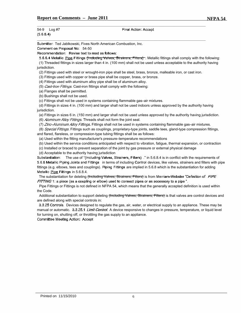
8.3* Purging requirements. The purging of piping shall be in accordance with Sections 8.3.1 through 8.3.3.
8.3.1* Piping systems required to be purged outdoors. The purging of piping systems shall be in accordance with the provisions of Sections 8.3.1.1 through 8.3.1.4 where the piping system meets either of the following: 1. The design operating gas pressure is greater than 2 psig. 2. The piping being purged contains one or more sections of pipe or tubing greater than 2 inches and meeting the size and length criteria of exceeding the lengths in Table 8.3.1.1.
8.3.1.1 Removal from Service. Where existing gas piping is opened, the section that is opened shall be isolated from the gas supply and the line pressure vented in accordance with Section 8.3.1.3. Where gas piping meeting the criteria of Table 8.3.1.1 is removed from service, the residual fuel gas in the piping shall be displaced with an inert gas.
Table 8.3.1.1 Size and Length of Piping†
Nominal Pipe Piping Size (in.)
Length of Piping (ft)
≥ 2 ½ < 3 > 50 ≥ 3 < 4 > 30 ≥ 4 < 6 > 15 ≥ 6 < 8 > 10
≥ 8 or larger Any length For SI units: 1 inch = 25.4mm; 1 ft =304.8mm. † CSST EHD size of 62 is equivalent to 2 in nominal size pipe or tubing.
8.3.1.2* Placing in operation. Where gas piping containing air and meeting the criteria of Table 8.3.1.1 is placed in operation, the air in the piping shall first be displaced with an inert gas. The inert gas shall then be displaced with fuel gas in accordance with Section 8.3.1.3.
8.3.1.3 Outdoor discharge of purged gases. The open end of a piping system being pressure vented or purged shall discharge directly to an outdoor location. Purging operations shall comply with all of the following requirements:
1. The point of discharge shall be controlled with a shutoff valve. 2. The point of discharge shall be located at least 10 feet from sources of ignition, at least 10
feet from building openings and at least 25 feet from mechanical air intake openings. 3. During discharge, the open point of discharge shall be continuously attended and
monitored with a combustible gas indicator that complies with Section 8.3.1.4. 4. Purging operations introducing fuel gas shall be stopped when 90% fuel gas by volume is
detected within the pipe. 5. Persons not involved in the purging operations shall be evacuated from all areas within 10
ft of the point of discharge. 8.3.1.4* Combustible Gas Indicator. The c Combustible gas indicators used during purging operations shall be listed and shall be calibrated in accordance with the manufacturer’s instructions and recommended schedule. The c Combustible gas indicators used for pipe discharge monitoring shall numerically display a volume scale from 0% to 100% with a resolution of not greater than in 1% or smaller increments.

2 NFPA 54 Log #CC9 Rec A2011 ROC
8.3.2* Piping systems allowed to be purged indoors or outdoors. The purging of piping systems shall be in accordance with the provisions of Section 8.3.2.1 where the piping system meets both of the following:
1. The design operating pressure is 2 psig or less. 2. The piping being purged is constructed entirely from pipe or tubing of 2 inch nominal size
or smaller, or larger pipe or tubing with lengths shorter than specified in not meeting the size and length criteria of Table 8.3.1.1.
8.3.2.1* Purging procedure. The piping system shall be purged in accordance with one or more of the following:
1. The piping shall be purged with fuel gas and shall discharge to the outdoors.
2. The piping shall be purged with fuel gas and shall discharge to the indoors or outdoors through an appliance burner not located in a combustion chamber. Such burner shall be provided with a continuous source of ignition.
3. The piping shall be purged with fuel gas and shall discharge to the indoors or outdoors through a burner that has a continuous source of ignition and that is designed for such purpose.
4. The piping shall be purged with fuel gas that is discharged to the indoors or outdoors, and the point of discharge shall be monitored with a listed combustible gas detector in accordance with 8.3.2.2. Purging shall be stopped when fuel gas is detected.
5. The piping shall be purged by the gas supplier in accordance with written procedures.
8.3.2.2 Combustible Gas Detector. The c Combustible gas detectors used during purging operations shall be listed and shall be calibrated or tested in accordance with the manufacturer’s instructions and recommended schedule. The c Combustible gas detectors used for pipe discharge monitoring shall be capable of indicateing the presence of fuel gas.
8.3.3 Purging appliances and equipment. After the piping system has been placed in operation, appliances and equipment shall be purged before being placed into operation. .
ANNEX A A.8.3 The process of purging gas piping that contains fuel gas or charging gas piping that is full of contains air with fuel gas must be performed in a manner that will minimize the potential for a flammable mixture to be developed within the piping. Also, a significant amount of flammable gas should not be released within a confined space.
Natural gas and propane suppliers add a distinctive odor to their gas to aid in its detection. Persons conducting purging operations should not rely upon their sense of smell. However, When a new gas piping system is brought into service and unodorized gas is detected, the company supplying the gas should be contacted to inform it of the situation and to determine what action should be taken. (More information on odorization of fuel gas is available in Odorization Supplement to the National Fuel Gas Code Handbook.)
A.8.3.1 Section 8.3.1 describes the characteristics of gas piping systems that are required to be purged only to the outdoors. The criteria were selected to distinguish between piping systems

3 NFPA 54 Log #CC9 Rec A2011 ROC
located in industrial, large commercial, and large multifamily buildings from those located in light commercial and smaller residential buildings. The gas piping systems installed in industrial, large commercial and large multifamily buildings are considered to be larger more complex systems for the purposes of defining their purging requirements. Because of their larger pipe volumes or potential for higher flow rates, these systems require procedures to ensure that a large volumes of fuel gases are is not released to the indoors and that flammable mixtures do not occur within the piping itself. Installers of these complex systems deal with considerably more variables that may result in a higher potential for discharge of large gas volumes during purging operations. Specific occupancy categories such as industrial, manufacturing, commercial and large multifamily were not included in the fuel gas code. U.S. building codes define these occupancies for the purpose of construction and safety requirements. There is no general relation between the occupancy types, as defined by the building codes, and the size of gas piping system to be installed in that occupancy. The gas piping size and operating pressure are based on the nature of the piping system and gas appliances to be installed and are not dependent upon a building’s occupancy type or classification.
A.8.3.1.2 It is recommended that the oxygen levels in the piping be monitored during the purging process to determine when sufficient inert gas has been introduced. The manufacturer’s instructions for monitoring instruments must be followed when performing purge operations.
A.8.3.1.4 Combustible gas indicators are available with different scales. For purging, it is necessary to use the percent gas in air scale and to follow the manufacturer’s operating instructions. The % LEL scale should not be used as it is not relevant to purging.
Users should verify that the indicator will detect fuel gas in the absence of oxygen. Many combustible gas indicators will not indicate fuel gas concentration accurately if no oxygen is present.
A.8.3.2 The criteria were selected to describe typical gas piping systems located in light commercial and the smaller residential family buildings. Gas piping systems installed in these buildings are considered to be smaller and less complex systems for the purposes of defining their purging requirements. Installers have familiarity with purging these systems and the potential for discharge of large gas volumes during purging operations is low. Also see A.8.3.1.
A.8.3.2.1 Where small piping systems contain air and are purged to either the indoors or outdoors with fuel gas, a rapid and uninterrupted flow of fuel gas must be introduced into one end of the piping system and vented out of the other end so as to prevent the development of a combustible fuel/air mixture. Purging these systems can be done either using a source of ignition to ignite the fuel gas or by using a listed combustible gas indicator detector that can detect the presence of fuel gas.

Report on Comments – June 2011 NFPA 54_______________________________________________________________________________________________54-19 Log #8
_______________________________________________________________________________________________James Ranfone, American Gas Association
54-97Adopt the approved 2009 Edition TIA/Amendment language with additional revisions as follows:
****Insert Include 54_L8_R.doc Here****
The Natural Fuel Gas Code Committee adopted revised coverage as the TIA/Addenda to the 2009edition. This revision was heavily revised from the ROP material initially processed by the committee. The reason forthe additional revisions and edits are as follows:● 8.3.1 #2 – To coordinate with Table 8.3.1.1 changes. The word “pipe and tubing” is replaced with “piping” which
means the same for editorially simplification.● Table 8.3.1.1 – A range was added to the pipe sizes to accommodate both pipe and tubing sizes. A review of the
Copper Development Association’s , found pipe and tubing sizes that fall between the pipesizes in the original table. For example, the old table did not contain a 3 ½ nor 5 inch tube sizes. Adding the rangeswould also cover all ACR tubing sizes. The word “pipe” is revised to “piping” to include tubing products. A tablefootnote is being added to explain that the current CSST maximum 62 size is equivalent to a 2 inch pipe/tubing size.Therefore, the user would know that the table does not apply to CSST who purging would fall under 8.3.2.● 8.3.2 #2 – To coordinate with Table 8.3.1.1 changes. The word “pipe and tubing” is replaced with “piping” which
means the same for editorially simplification.● 8.3.2.1 – The section’s charging statement was editorially revised to read “shall be permitted to be purged with fuel
gas” in order to replace the “shall be purged with fuel gas” repeated in #1 through #4. The revision editorially improvesthe section.● 8.3.2.1 #1 thought #4 – Each was revised to make clearer that that the “point of discharge” is what the requirement is
referring to. This make this section consistent with the language used in 8.3.1.3 #1 & #2.● 8.3.2.2 – Editorial revisions. The phrases “used during purging operations” and “used for pipe discharge monitoring”
since the gas detectors that the code requires are being used during purging or monitoring operations. The secondrevision is also editorial since the gas detector shall have a “capability” to indicate fuel gas.● A.8.3 – Editorial revisions. Two changes are adding in the word “leak” before detection since this is the main reason
odorant is added. A new sentence is added to provide guidance that persons involved in purging should use their senseof smell. This sentence ties in with the next sentence that when unordorized gas is detected then the gas suppliershould be contacted.● A.8.3.1– Editorial.● A.8.3.2.1 – Section 8.3.2.1 allows the use of a gas detector and not a gas indicator.
Refer to committee action on 54-18 (Log #CC9).
12Printed on 11/15/2010
1 NFPA 54 Log #8 Rec A2011 ROC
8.3* Purging requirements. The purging of piping shall be in accordance with Sections 8.3.1 through 8.3.3
8.3.1* Piping systems required to be purged outdoors. The purging of piping systems shall be in accordance with the provisions of Sections 8.3.1.1 through 8.3.1.4 where the piping system meets either of the following: 1. The design operating gas pressure is greater than 2 psig. 2. The piping being purged contains one or more sections of pipe or tubing greater than 2
inches and exceeding the lengths piping specified in Table 8.3.1.1. 8.3.1.1 Removal from Service. Where existing gas piping is opened, the section that is opened shall be isolated from the gas supply and the line pressure vented in accordance with Section 8.3.1.3. Where gas piping meeting the criteria of Table 8.3.1.1 is removed from service, the residual fuel gas in the piping shall be displaced with an inert gas.
Table 8.3.1.1 Size and Length of Piping*
Nominal Pipe Piping Size (in.)
Length of Piping (ft)
≥ 2 ½ < 3 > 50 ≥ 3 < 4 > 30 ≥ 4 < 6 > 15 ≥ 6 < 8 > 10
≥ 8 or larger Any length For SI units: 1 inch = 25.4mm; 1 ft =304.8mm. *The largest CSST EHD size of 62 is equivalent to a nominal 2 in pipe or tubing size.
8.3.1.2* Placing in operation. Where gas piping containing air and meeting the criteria of Table 8.3.1.1 is placed in operation, the air in the piping shall first be displaced with an inert gas. The inert gas shall then be displaced with fuel gas in accordance with Section 8.3.1.3.
8.3.1.3 Outdoor discharge of purged gases. The open end of a piping system being pressure vented or purged shall discharge directly to an outdoor location. Purging operations shall comply with all of the following requirements:
1. The point of discharge shall be controlled with a shutoff valve. 2. The point of discharge shall be located at least 10 feet from sources of ignition, at least 10
feet from building openings and at least 25 feet from mechanical air intake openings. 3. During discharge, the open point of discharge shall be continuously attended and
monitored with a combustible gas indicator that complies with Section 8.3.1.4. 4. Purging operations introducing fuel gas shall be stopped when 90% fuel gas by volume is
detected within the pipe. 5. Persons not involved in the purging operations shall be evacuated from all areas within 10
ft of the point of discharge. 8.3.1.4* Combustible Gas Indicator. The combustible gas indicator used during purging operations shall be listed and shall be calibrated in accordance with the manufacturer’s instructions and recommended schedule. The combustible gas indicator used for pipe discharge monitoring shall numerically display a volume scale from 0% to 100% with a resolution of not greater than 1% increments.

2 NFPA 54 Log #8 Rec A2011 ROC
8.3.2* Piping systems allowed to be purged indoors or outdoors. The purging of piping systems shall be in accordance with the provisions of Section 8.3.2.1 where the piping system meets both of the following:
1. The design operating pressure is 2 psig or less. 2. The piping being purged is constructed entirely from pipe or tubing of 2 inch nominal
size or smaller piping, or larger pipe or tubing piping with lengths shorter than specified in Table 8.3.1.1.
8.3.2.1* Purging procedure. The piping system shall be permitted to be purged with fuel gas in accordance with one or more of the following:
1. The piping shall be purged with fuel gas and shall point of discharge shall be to the outdoors.
2. The piping shall be purged with fuel gas and shall point of discharge either to the indoors or outdoors shall be through an appliance burner not located in a combustion chamber. Such burner shall be provided with a continuous source of ignition.
3. The piping shall be purged with fuel gas and shall point of discharge either to the indoors or outdoors shall be through a burner that has a continuous source of ignition and that is designed for such purpose.
4. The piping shall be purged with fuel gas that is point of discharged either to the indoors or outdoors, and the point of discharge shall be monitored with a listed combustible gas detector in accordance with 8.3.2.2. Purging shall be stopped when fuel gas is detected.
5. The piping shall be purged by the gas supplier in accordance with written procedures.
8.3.2.2 Combustible Gas Detector. The combustible gas detector used during purging operations shall be listed and shall be calibrated or tested in accordance with the manufacturer’s instructions and recommended schedule. The combustible gas detector used for pipe discharge monitoring shall be capable of indicateing the presence of fuel gas.
8.3.3 Purging appliances and equipment. After the piping system has been placed in operation, appliances and equipment shall be purged before being placed into operation. .
ANNEX A A.8.3 The process of purging gas piping full of fuel gas or charging gas piping that is full of air with fuel gas must be performed in a manner that will minimize the potential for a flammable mixture to be developed within the piping. Also, When purging piping systems using fuel gas a significant amount of flammable gas should not be released within a confined space. Natural gas and propane suppliers add a distinctive odor to their gas to aid in its leak detection. Persons conducting purging operations should not rely upon their sense of smell which can vary between individuals. However, when a new system is brought into service and unodorized gas is detected, the company supplying the gas should be contacted to inform it of the situation and to determine what action should be taken.
A.8.3.1 Section 8.3.1 describes the characteristics of gas piping systems that are required to be purged only to the outdoors. The criteria were selected to distinguish between piping systems located in industrial, large commercial, and large multifamily buildings from those located in light commercial and smaller residential buildings. The gas piping systems installed in industrial,

3 NFPA 54 Log #8 Rec A2011 ROC
large commercial and large multifamily buildings are considered to be larger more complex systems for the purposes of defining their purging requirements. Because of their larger pipe volumes or potential for higher flow rates, these systems require procedures to ensure that a large volumes of fuel gases are is not released to the indoors and that flammable mixtures do not occur within the piping itself. Installers of these complex systems deal with considerably more variables that may result in a higher potential for discharge of large gas volumes during purging operations. Specific occupancy categories such as industrial, manufacturing, commercial and large multifamily were not included in the fuel gas code. U.S. building codes define these occupancies for the purpose of construction and safety requirements. There is no general relation between the occupancy types, as defined by the building codes, and the size of gas piping system to be installed in that occupancy. The gas piping size and operating pressure are based on the nature of the piping system and gas appliances to be installed and are not dependent upon a building’s occupancy type or classification.
A.8.3.1.2 It is recommended that the oxygen levels in the piping be monitored during the purging process to determine when sufficient inert gas has been introduced. The manufacturer’s instructions for monitoring instruments must be followed when performing purge operations.
A.8.3.1.4 Combustible gas indicators are available with different scales. For purging, it is necessary to use the percent gas in air scale and to follow the manufacturer’s operating instructions. The % LEL scale should not be used as it is not relevant to purging.
A.8.3.2 The criteria were selected to describe typical gas piping systems located in light commercial and the smaller residential family buildings. Gas piping systems installed in these buildings are considered to be smaller and less complex systems for the purposes of defining their purging requirements. Installers have familiarity with purging these systems and the potential for discharge of large gas volumes during purging operations is low. Also see A.8.3.1.
A.8.3.2.1 Where small piping systems contain air and are purged to either the indoors or outdoors with fuel gas, a rapid and uninterrupted flow of fuel gas must be introduced into one end of the piping system and vented out of the other end so as to prevent the development of a combustible fuel/air mixture. Purging these systems can be done either using a source of ignition to ignite the fuel gas or by using a listed combustible gas indicator detector that can detect the presence of fuel gas.
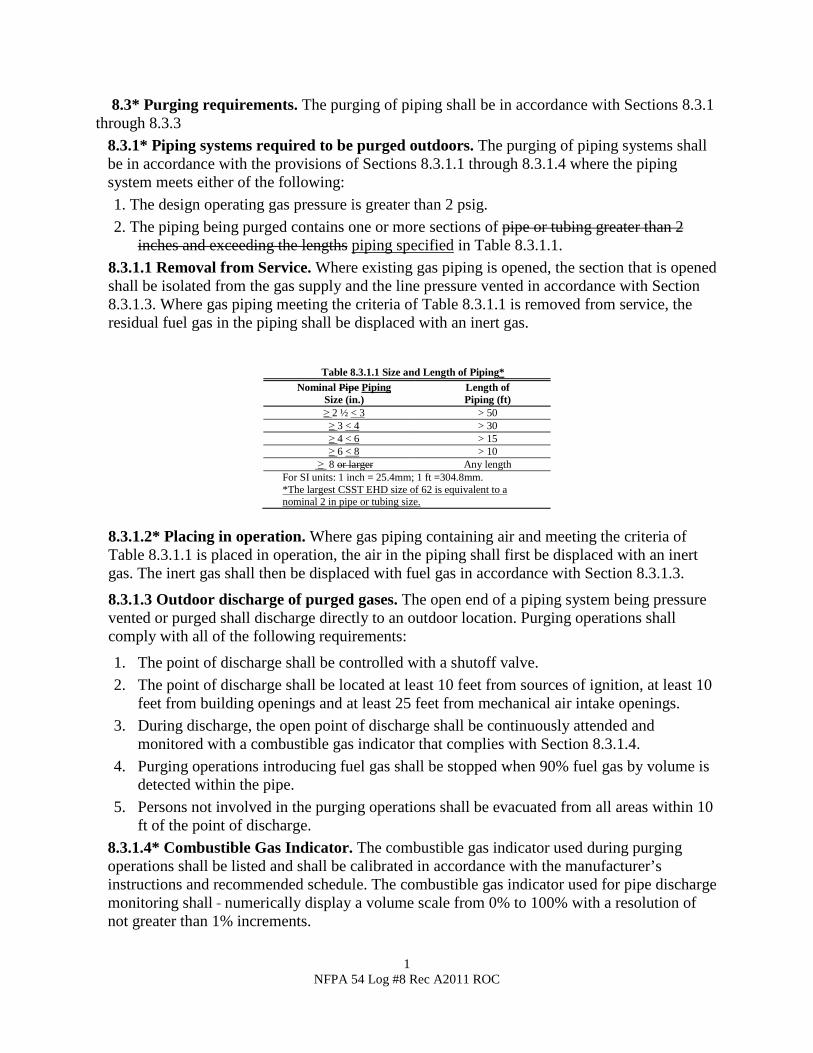
Report on Comments – June 2011 NFPA 54_______________________________________________________________________________________________54-20 Log #15
_______________________________________________________________________________________________Bruce J. Swiecicki, National Propane Gas Association
54-97Reject the proposal and delete all revised text.
The NFPA Standards Council and ANSI have approved a new Tentative Interim Amendment (TIA#54-09-3) and the wording in that document should form the basis for the code requirement.
The Committee reaffirms acceptance of the TIA with additional modifications as shown in 54-18(Log #CC9).
_______________________________________________________________________________________________54-21 Log #13
_______________________________________________________________________________________________Tim G. Dunn, Sr., Dunn Laboratories, Inc.
54-101I am requesting reconsideration on the proposed text. I would respectfully request a few minutes
with the upcoming Technical Committee meeting, not only to share my views but to solicit any feedback.Below grade installations, such as basements, cellars or pits, are not unlike the rather confined spaces
inside RVs and the interior spaces of boat/marine vessels, where the applicable codes provides such provisions. In the34 years that I have investigated fuel gas explosions, I have concluded below grade installations of propane appliancesand piping warrants supplemental detection, as already recommended by a number appliance manufacturers.
The TC reaffirms its ROP action and statement. No data is provided to support a higherincident rate for propane systems below grade compared to above grade. The committee notes that the code containsprovisions to prevent gas leakage, and believes that these are sufficient. The U. S. Consumer Product SafetyCommission issued a letter stating that there is not an increased likelihood of ignition of leaking fuel gas in a belowgrade propane installation.
13Printed on 11/15/2010

Report on Comments – June 2011 NFPA 54_______________________________________________________________________________________________54-22 Log #2
_______________________________________________________________________________________________Robert S. Boiko, R. Boiko Corporation
54-104Add text to read as follows:
9.1.10.1 Installation in Residential Garages. Appliances in residential garages and in adjacent spaces that open to thegarage and are not part of the living space of the dwelling unit shall be installed so that all burners and burner ignitiondevices are located not less than 18 in. (460 mm) above the floor unless listed as flammable vapor ignition resistant by arecognized listing agency and certified as safe to use near or around flammable liquids and vapors by the originalequipment manufacturer.
Before 2002, NEC Codes, NFPA 54, one probably could not find (till now) any code countermanding,superseding the Manufacturers; a new NFPA precedent over a clear, direct warning from an original equipmentmanufacturer. The NFPA did not potentially (my opinion not NFPA) place people in danger by publishing a code of thiskind; unsupported by any known water heater manufacturer. NFPA seems to rely on perceived silence to determinethat this Code shall stand, even with zero affirmative written support directly from the OEMs. NFPA 54 2009 9.1.9 iswrong where it references FVIR. Right there! Every known FVIR Water Heater OEM includes numerous text andgraphic cautions about explosions /fire dangers when Flammable Vapors are near. 9.1.10.1, the code that should bemodified as I proffer, flows from the incorrect logic of 9.1.9. How you may prove the code is deficient, the even moredata you, )producing a body), demand? Please produce one letter from the manufacturers, A. O. Smith or Rheem thatstates they approve and accept legal liability for all FVIR water heaters being proximately installed on the ground, not 18in. elevated, as stated 9.1.9 "...where the open use, handling, or dispensing of flammable liquids occurs..."Note: Supporting material is available for review at NFPA Headquarters.
The TC rejected the comment because the definition of "listed" indicates third-party testing andlisting. In addition, section 9.1.10 addresses installation in residential garages only. It is not intended to addresshazardous locations, such as where flammable liquids or vapors are routinely handled or dispensed. Finally, the listingstandard, ANSI Z21.10.1,
, requires user instructions and product labels to include information on prohibited locations, and warnings for usersagainst the handling or use of flammable liquids or vapors in the vicinity of a water heater.
_______________________________________________________________________________________________54-23 Log #22
_______________________________________________________________________________________________Ronald R. Czischke, Underwriters Laboratories Inc.
54-107Revised text to read as follows
(2) Outdoor. Where Outdoor gas hose connectors are permitted used to connect portable outdoor appliances, theconnector shall be listed in accordance with ANSI Z21.54 Gas Hose Connectors for Portable Outdoor Gas-FiredAppliances.
My comment is that reference to only ANSI Z21.54 be removed from the proposal. Connectors shouldbe listed to ensure they are suitable for the application. Hose connectors that comply with UL569 are suitable forlow-pressure natural gas service to connect to portable gas fired appliances. The substantiation from the originalproposal incorrectly stated that UL569 specifically stated it is not for use with portable outdoor gas fired appliances. TheScope in UL569 states that it does not apply to hose connectors that are investigated to ANSI Z21.54. This statement ismeant to be a cross reference only.
The committee rejects the comment because ANSI Z21.58, Outdoor Cooking Gas Appliances,requires a connector listed in accordance with ANSI Z21.54. ANSI Z21.54 incorporates more comprehensive testprocedures than UL 569 that are more relevant to this application.
14Printed on 11/15/2010

Report on Comments – June 2011 NFPA 54_______________________________________________________________________________________________54-24 Log #27
_______________________________________________________________________________________________Charlie Olds, Marshall Gas Controls
54-107The NFPA 54 Technical Committee should reject this proposal because the justification of a safety
issue does not exist and the explanations presented at not completely factual. [Proposed revision NFPA 54 Section9.6.2 (2) ]
The NFPA 54 Technical Committee should reject ROP 54-107 because without factual data,thermoplastic hose is safe and an acceptable alternative to other connectors used in the industry. This proposal thecommittee accepted has inaccurate substantiation, as show above. UL 21/569 hose and Z21.54 connectors have bothbeen used safely for this application for many years, both have their advantages and disadvantages, the committeeshould not restrict the use of one over the other. Do not change Section 9.6.2 (2) for the benefit of one product.The argument this proposal is trying to make is not correct because thermoplastic hose has been used for over 20
years in outdoor gas grills with millions sold every year on grills, construction heaters, gas illuminating appliances plusused every day without the issues this proposal is addressing. Both types of connectors discussed in this proposal havetheir advantages and disadvantages but one type should not be restricted over the other, as the Technical Committeehas agreed to for this proposal.This proposal references NFPA Statistics and Safety Tips but nowhere does it describe a hose issue. The proposal
describes statistics and safety for gas grills, charcoal grills, charcoal starter fluid, soap and water leak checks, butnothing from official statistics stating UL 569 hose has field problems or “hose assemblies catching on fire”, such asincorrectly stated in this proposal. The official fire incident data is gathered by a standardized coding process and doesnot identify the component failure, so the cause could be the cylinder connections, relief valve, hose assembly,appliance controls, or something else in a gas appliance fire.The proposal incorrectly writes that the UL 569 standard “specifically states: 1. Not for use with Portable Outdoor Gas
Fired Appliances”. The UL 569 scope only says it does not apply to ANSI Z21.24 or ANSI Z21.54 connectors and doesnot imply that UL 569 hose can’t be used on outdoor appliances. Those familiar with UL hose standards know that UL isin process of changing their hose standard to exceed 60 inches in length and include coupling requirements, which willmake these arguments in the proposal invalid.The counter-side of this proposal should look at the disadvantages plastic coated metallic tubing has when compared
to thermoplastic hose:- An advantage UL 21/569 hose assemblies have over Z21.54 assemblies is the resistance to abrasion and resulting
leak through the pressure retaining wall. Z21.54 Scope states these connectors “depend for gas-tightness on the wallstructure of the hose material.” Thermoplastic hose pressure retaining wall thickness is many magnitudes thicker than aZ21.54 pressure retainer wall. The Z21.54 Scope states for use on systems not exceeding 1/2 psi where UL 569 hosecan be used on 250 psi systems bring an extra factor of safety for overpressure situations.- ANSI Z21.54 applies to gas hose connectors but the definition states “The design and application presuppose that the
connector will not be pressurized when the appliance served by the connector is not in use.” The gas supply to theseoutdoor appliances will not always be shut off when not in use. The scope only applies to connectors less than 1/2 psiso the Z21.54 connector will not withstand any overpressure situation.- Any wear of the thin outside plastic protective coating of Z21.54 connectors exposes the stainless steel to
degradation, such as from chloride cleaners used on grills that can cause stress corrosion cracking in SST. Bare metalexposed to concrete can also initiate corrosion.- Thin metallic walls are more susceptible to holes from lightning strike or electrical spark as recently acknowledged
with CSST and new bonding requirements. Thermoplastic hose is a dielectric so it is thoroughly insulated.- Flexibility and fatigue life for metallic connectors is low, and the appliance should not be frequently moved, as
compared to thermoplastic connectors that withstand 25,000 cycle 180 degree bend testing. Z21.54 section 2.4.5 onlyrequire 20 cycles of 90 degree bends.- Z21.24/54 connectors have a low puncture resistance in the thin wall SST, comparable to CSST and their strike plate
requirements.
It was reported to the TC that ANSI Z21.54 does not prohibit the use of thermoplastic hose andthat at least one thermoplastic hose connector is listed to ANSI Z21.54. As stated in 54-9 (Log #7), the committeebelieves that product listed to UL 569 is not appropriate for use with outdoor appliances.
15Printed on 11/15/2010

Report on Comments – June 2011 NFPA 54
_______________________________________________________________________________________________54-25 Log #14
_______________________________________________________________________________________________Tim G. Dunn, Sr., Dunn Laboratories, Inc.
54-108I am requesting reconsideration on the proposed text. I would respectfully request a few minutes
with the upcoming Technical Committee meeting, not only to share my views but to solicit any feedback.While Section 7.7.2 "Cap all Outlets" should prevent any gas discharge, regardless of the valve
position, in my 34 years experience of investigating fuel gas fires/explosions, many times a person disconnecting andremoving an appliance is not experienced or familiar with the codes, such that the outlet is left uncapped; these valves,with handle perpendicular when "closed", can stick out thus are prone to accidental opening with a single plane force. InTexas alone, I have become aware of a number of related incidents.
The proponent provides no substantiation that the installation of locking valves would haveprevented any accidents. The Code requires that all disconnected outlets be capped or plugged. The TC believes thatrequiring a lockable or latching shutoff device will not address the underlying education/training issue and qualifiedagency requirement.
_______________________________________________________________________________________________54-26 Log #18
_______________________________________________________________________________________________Jim Smelcer, Lochinvar Corp
54-111Delete new text to read as follows:
The following text is proposed to be deleted:Chapter 10 Installation of Specific Appliances(10.1 through 10.1.2 unchanged)
Where the room size in comparison with the size of the appliance is tobe calculated, the total volume of the appliance is determined from exterior dimensions and is to include fancompartments and burner vestibules, where used. Where the actual ceiling height of a room is greater than 8 ft (2.4 m),the volume of the room is figured on the basis of a ceiling height of 8 ft (2.4 m).
This paragraph should not be deleted. Installation requirements for appliances should maintain theadditional volume specifications to account for ventilation/dilution air to help prevent build up of expelled fuel gasesthrough leak limiting devices from gas train components should gas pressure regulators fail.Justification: NFPA currently exempts ventilation space requirements for direct vent boilers that are mandated to
non-direct vent boilers. CSDAFB Committee (CSD-1 for short) (ASME Controls and Safety Devices for AutomaticallyFire Boilers) have been working on coverage for that standard to address field history complaints involving direct ventinstalled boilers with vent leak limiters. There have been documented reports of accidents passing through thatcommittee linked to gas buildup, and the room was not ventilated due. This coverage helps provide the additionalvolume of air for dilution and disassociation of the gas molecules to reduce the risk of reaching the flammability point.Otherwise — Suggest an item for new business — remove the exemption for ventilation air requirements for direct vent
boilers.
The paragraph in question is not a stand-alone paragraph. Retaining that paragraph withoutcontext does not provide the coverage sought by the commenter, and would make the Code incomplete on the subject.If there is an issue regarding multiple vent limiters in a room, a proposal should be developed to address that specificissue for the next revision cycle.
16Printed on 11/15/2010

Report on Comments – June 2011 NFPA 54_______________________________________________________________________________________________54-26a Log #CC2
_______________________________________________________________________________________________Technical Committee on National Fuel Gas Code,
The installation of air-conditioning appliances shall comply with thefollowing requirements:
) Listed air conditioning appliances shall be installed with clearances in accordance with the manufacturer’sinstructions.
Unlisted air-conditioning appliances shall be installed with clearances from combustible material of not less than 18in. (460 mm) above the appliance and at the sides, front, and rear and in accordance with the manufacturer’s installationinstructions those specified in Table 10.2.3(a).
) Listed and unlisted air Air-conditioning appliances shall be permitted to be installed with reduced clearances tocombustible material, provided that the combustible material or appliance is protected as described in Table 10.2.3(b)and such reduction is allowed by the manufacturer installation instructions.
Paragraph 10.2 covers air-conditioning appliances and 10.3 covers central heating boilers andfurnaces. The requirements are similar and in the ROP the revisions to these 2 sections provided different requirementsfor clearance to unlisted appliances. As the sections are similar, and many times cover the same appliance, theproposed revision will make the section consistent with each other and treatment of clearance to combustibles in othersections of the code.Paragraph 10.3.2, as revised in the ROP is shown below.10.3.2.3 Unlisted central heating furnaces and low-pressure boilers shall be installed with clearances from combustible
material not less than those specified in Table 10.2.3(a).
_______________________________________________________________________________________________54-26b Log #CC3
_______________________________________________________________________________________________Technical Committee on National Fuel Gas Code,
Relocate Figures 10.3.2.2 (a), (b), and (c) to Annex A.References to the figures has been deleted from chapter 10 in the ROP. As the figures are not
requirements they are relocated to Annex A.
_______________________________________________________________________________________________54-26c Log #CC4
_______________________________________________________________________________________________Technical Committee on National Fuel Gas Code,
Relocate Figure 10.27.1.3 to Annex A.References to the figures has been deleted from 10.27.1.3 in the ROP. As the figure is not a
requirement it is relocated to Annex A.
17Printed on 11/15/2010

Report on Comments – June 2011 NFPA 54_______________________________________________________________________________________________54-27 Log #16
_______________________________________________________________________________________________Bruce J. Swiecicki, National Propane Gas Association
54-118Revise as follows:
. Appliances supplied with means for automatic ignition shall be checked for operation withinthe parameters provided by the manufacturer. Any adjustments made shall be in accordance with the manufacturer’sinstallation instructions or recommendations.
. Where required by the manufacturer’s installation instructions, all protective devicesfurnished with the appliance, such as a limit control, fan control to blower, temperature and pressure relief valve,low-water cutoff device, or manual operating features, shall be checked for operation within the parameters provided bythe manufacturer. Any adjustments made shall be in accordance with the manufacturer’s installation instructions orrecommendations.
Although the committee stated that only written instructions from the manufacturer should be followed,it is important to permit verbal instructions because the service technician will sometimes need to contact themanufacturer or his agent to clarify how to perform a field modification properly. The following is quoted from a memberof NPGA that installs appliances:
The committee reaffirms its ROP action and statement. The proposal is accepted withoutincluding manufacturer’s recommendations, which could be verbal or written. The committee believes that only thewritten instructions from the manufacturer should be followed. This is not intended to prevent the technician from callingthe manufacturer for troubleshooting or diagnostic information.
_______________________________________________________________________________________________54-28 Log #CC11
_______________________________________________________________________________________________Technical Committee on National Fuel Gas Code,
54-122Revise Table 12.5.1 as follows:
****Insert Table 12.5.1 Here****The recommended changes in Proposal 54-1 delete several important items in Table 12.5.1, which are
needed. The revised table incorporates a new column where this information is located.
18Printed on 11/15/2010

54/LCC11/Tb 12.5/A2011/ROC
Table 12.5.1 Type of Venting System to Be Used
Appliances Type of Venting System Location of Requirements
Listed Category I appliances Listed appliances equipped with draft hood Appliances listed for use with Type B gas vent
Type B gas vent (see Section 12.7) Chimney (see Section 12.6) Single-wall metal pipe (see Section 12.8) Listed chimney lining system for gas venting (see 12.6.1.3) Special gas vent listed for these appliances (see 12.5.3)
12.7 12.6 12.4 12.6.1.3 12.5.3
Listed vented wall furnaces
Type B-W gas vent (see Section 12.7, Section 10.27)
12.7, 10.27
Category II appliances Category III appliances Category IV appliances
As specified or furnished by manufacturers of listed appliances (see 12.5.2, 12.5.3)
12.5.2, 12.5.3
Incinerators, outdoors Single-wall metal pipe [see Section 12.8, 12.8.3(3)]
12.8
Incinerators, indoors Chimney (see Section 12.6) 12.6 Appliances that can be converted to use solid fuel
Unlisted combination gas- and oil-burning appliances
Combination gas- and solid fuel–burning appliances
Appliances listed for use with chimneys only
Unlisted appliances Listed combination gas- and oil-burning appliances
Type L vent (see Section 12.7) or chimney (see Section 12.6)
12.7 12.6
Decorative appliance in vented fireplace
Chimney (see 10.6.2) 10.6.2
Gas-fired toilets Single-wall metal pipe (see Section 12.8, 10.25.3)
12.8, 10.25.3
Direct vent appliances See 12.3.5 Per manufacturer’s instructions 12.3.5 Appliances with integral vents
See 12.3.6 Per manufacturer’s instructions 12.3.6

Report on Comments – June 2011 NFPA 54_______________________________________________________________________________________________54-29 Log #CC3
_______________________________________________________________________________________________Technical Committee on National Fuel Gas Code,
54-1Relocate Figure 12.6.2.1 to Annex A.12.6.2.1.
Figure 12.6.2.1 illustrates the requirement in paragraph 12.6.2.1. It is not a requirements and isrelocated to Annex A, which is appropriate for illustrative artwork.
_______________________________________________________________________________________________54-30 Log #CC2
_______________________________________________________________________________________________Technical Committee on National Fuel Gas Code,
54-1Revise text to read as follows:
12.7 Gas Vents. See 3.3.107.2. ([See Definition 3.3.107.2])For consistency with other committee actions to delete “See” statements.
_______________________________________________________________________________________________54-31 Log #CC4
_______________________________________________________________________________________________Technical Committee on National Fuel Gas Code,
54-1Relocate Figure 12.7.4.2 to A.12.7.4.2.
Figure 12.7.4.2 illustrates the requirement in paragraph 12.7.4.2. It is not a requirement and isrelocated to Annex A, which is appropriate for illustrative artwork.
_______________________________________________________________________________________________54-32 Log #CC14
_______________________________________________________________________________________________Technical Committee on National Fuel Gas Code,
54-132Revise text to read as follows:
12.9.6 Vent terminals systems for Category IV appliances that terminate through an outside wall of a building anddischarge flue gases perpendicular to the adjacent wall shall be located not less than 10 feet horizontally from anoperable opening in an adjacent building.Exception: This shall not apply to vent terminals that are 2 feet or more above or 25 feet or more below operable
openings.The TC reaffirmed the action in proposal 54-132. It was reported to the TC that Category IV
appliances where the flue gases have some velocity are most likely to impinge on adjacent buildings and potentiallyenter through operable windows. Therefore, the TC limited the requirement to category IV appliances. The TC alsospecified that the perpendicular discharge because the National Fire Protection Research Foundation report on thesubject indicates that the perpendicular discharge produces the highest concentrations at adjacent buildings.
19Printed on 11/15/2010

Report on Comments – June 2011 NFPA 54_______________________________________________________________________________________________54-33 Log #10
_______________________________________________________________________________________________James Ranfone, American Gas Association
54-132Delete new section 12.9.6.
12.9.6 Vent terminals that terminate through an outside wall of a building shall be located not less than 10 feethorizontally from an operable opening in an adjacent building.Exception: This shall not apply to vent terminals that are 2 feet or more above or 25 feet or more below operable
openings.
The NFPA Foundation research project was a very limited computer modeling exercise to exploreventing plume patterns as a first step to determine whether addition modeling and field verification was needed. Theresearch was limited in scope and was not meant to be used to set minimum distances to adjacent building openings.For example, the modeling looked at only one building type & location – adjacent two story single-family dwellings set ina suburban location, a limited number of appliance types and inputs, and one vent termination location 12-inch abovegrade. The issue of vent plume impingement on adjacent structures is nuisance issue related to ice buildup. Thisresearch project does not justify the 10 ft distance that the new section would impose on all vent terminations. It isoverly restrictive applying to all construction.
The TC reaffirms its ROP action on 54-132. Refer to 54-32 (Log #CC14) for furthermodifications of this section.
_______________________________________________________________________________________________54-34 Log #CC10
_______________________________________________________________________________________________Technical Committee on National Fuel Gas Code,
54-7Add new text to read as follows:
A.3.2.3 Code. The decision to designate a standard as a “code” is based on such factors as the size and scope of thedocument, its intended use and form of adoption, and whether it contains substantial enforcement and administrativeprovisions.
A new A.3.2.2 is recommended in the NFPA Manual of Style and provides explanation of the internet.
_______________________________________________________________________________________________54-35 Log #12
_______________________________________________________________________________________________James Ranfone, American Gas Association
54-147Print the full revised Table A.5.6 in the ROC.
The Committee accepted in principle and revised Table A.5.6. However, the original table is shown inthe ROP while the revised table is not shown. The preprint includes the revised Table but the preprint is not consideredto be part of the public review. To ensure full public review and comment, the revised table should be printed in theROC.
****Insert 54_L12_Table A.5.6 Here****
20Printed on 11/15/2010

54_L12_Tb A.5.6_A2011 ROC 1
Table A.5.6 Pipe, Tube, Fittings, and Joints for Natural Gas and Liquefied Petroleum Gas Applications Metallic Pipe
Pipe
Fitting Types Joint Types
Other Requirements Material Standard
Black Steel Minimum
Schedule 40
ASTM A106† Steel Malleable Iron Steel Cast Iron ASME B16.1†
Brass Bronze Special
Threaded Flanged
Threads per ASME B1.20.1† Special fittings shall be appropriate for the application and acceptable to AHJ
Galvanized Steel minimum
Schedule 40
ASTM A53†
Wrought Iron Minimum
Schedule 40 Also known as
low iron or wrought steel
ASTM B36.10M†
Copper None Specified Cast Copper Alloy
Bronze Brass
Special
None Specified Prohibited where the gas contains more than an average of 0.3 grains of hydrogen sulfide per 100 scf of gas (0.7 mg/100 L). Threads cannot form the joint seal Special fittings shall be appropriate for the application and acceptable to AHJ
Copper Alloy (Brass)
None Specified
Aluminum ASTM B241† Aluminum Special
None Specified
Alloy 5456 is prohibited Threads cannot form the joint seal Coated to protect against external corrosion where it is in contact with masonry, plaster, or insulation, or is subject to repeated wettings by such liquids as water, detergents, or sewage. Aluminum alloy pipe shall not be used in exterior locations or underground. Special fittings shall be appropriate for the application and acceptable to AHJ
Metallic Tubing Pipe
Fitting Types Joint Types Other Requirements Material Standard
Copper ASTM B88† ASTM B280†
Cast Copper Alloy
Wrought Copper Press fittings
meeting ANSI LC4†
Forged Copper Alloy
Special
Brazed Flanged/Brazed
Brazed Mechanically
Pressed (Crimped)
Flared
Prohibited where the gas contains more than an average of 0.3 grains of hydrogen sulfide per 100 scf of gas (0.7 mg/100 L). Brazed joints fabricated with alloys having a melting temperature greater than 1000º F Brazing alloys contain less than 0.05% Phosphorous Minimum melting temperature greater than 1000º F Brazing alloys contain less than 0.05% Phosphorous Flares, SAE J533 for single 45º flares Special fittings shall be appropriate for the application and acceptable to AHJ
CSST ANSI LC 1 / CSA 6.26†
ANSI LC 1 / CSA 6.26†
Manufacturer’s installation instructions
Installation in accordance with the manufacturer’s installation instructions.

54_L12_Tb A.5.6_A2011 ROC 2
Aluminum ASTM B 210† ASTM B 241†
Copper Alloy (Brass) Special
Compression Coated to protect against external corrosion where it is in contact with masonry, plaster, or insulation or is subject to repeated wettings by such liquids as water, detergent, or sewage. Aluminum-alloy tubing shall not be used in exterior locations or underground. Special fittings shall be appropriate for the application and acceptable to AHJ
Steel ASTM A 539†
ASTM A 254† Special Special fittings shall be appropriate for the application and
acceptable to AHJ
Non-Metallic Pipe & Tube Pipe
Fitting Type Joint Types Other Requirements Material Standard
Polyethylene (PE)
ASTM D 2513† Polyethylene (PE) ASTM D 2513†
(Heat fusion) Service head adapters meeting Category I of
ASTM D 2513† Connections to Metallic Pipe meeting ASTM D 2513†, ASTM F 1973†,
or ASTM F 2509†
Manufacturer’s instructions Compression-type mechanical joints Heat Fusion
Pipe and tubing installed outdoors underground only Pipe shall be marked “gas” and “ASTM D 2513 Plastic pipe, tubing, fittings and joints in undiluted liquefied petroleum gas piping systems shall be in accordance with NFPA 58†
PVC UL 651†
Schedule 40 or 80 PVC UL 651†
Schedule 40 or 80 Manufacturer’s
instructions Regulator vents only Outdoor installation only
†Required standard. See Chapter 5 for standard title.

Report on Comments – June 2011 NFPA 54_______________________________________________________________________________________________54-36 Log #11
_______________________________________________________________________________________________James Ranfone, American Gas Association
54-148Revise Table A.6.1 as follows:
*****Insert Table A.6.1 Log #11 Here****
The largest pipe diameter printed in the code appears in tables 6.2(a) and 6.2(b) which is 12 inches.
_______________________________________________________________________________________________54-37 Log #29
_______________________________________________________________________________________________Edward Angelone, National Grid
54-97Revise text to read as follows:
The process of purging gas piping full of fuel gas or charging gas piping that is full of air with fuel gas must beperformed in a manner that will minimize the potential for a flammable mixture to be developed within the piping. Also,When purging piping systems using fuel gas a significant amount of flammable gas should not be released within aconfined space. Natural gas and propane suppliers add a distinctive odor to their gas to aid in its leak detection. There isalways a possibility new piping can lose odor (odorant fade) due to stagnant piping and exceptionally long runs. Personsconducting purging operations should not rely upon their sense of smell, which has been found to vary betweenindividuals. However, when a new system is brought into service and unodorized gas is detected, the companysupplying the gas should be contacted to inform it of the situation and to determine what action should be taken.
Mentioning natural gas suppliers add a distinctive odor and then a reference about when unodorizedgas is detected could be confusing or misleading to think the odorant was not added. Providing a possible cause ofodorant fade is educational.
Refer to committee action on 54-18 (Log #CC9).
_______________________________________________________________________________________________54-38 Log #CC5
_______________________________________________________________________________________________Technical Committee on National Fuel Gas Code,
54-145Number text moved to Annex A in Proposal 54-135 as A.12.11.6, and change "shall" to "should".
Paragraph 12.11.6 was deleted in Proposal 54-135 and moved to Annex A. Number the deleted textas A.12.11.6 to tie it to current 12.11.7, Joints (which will be renumbered 12.11.6). Also, change “shall” to “should” in theparagraph.
21Printed on 11/15/2010

1 NFPA 54 Log #11 Tbl A.6.1 Rec A2011 ROC
Table A.6.1 Nominal Pipe
Nominal Pipe Diam.
Nominal Pipe Diam.
in. mm in. mm 1/8 6 8 200 3/16 7 10 250 1/4 8 12 300 3/8 10 14 350 1/2 15 16 400 5/8 18 18 450 3/4 20 20 500 1 25 24 600
1 ¼ 32 28 700 1 ½ 40 30 750 2 50 32 800
2 ½ 65 36 900 3 80 40 1000
3 ½ 90 44 1100 4 100 48 1200
4 ½ 115 52 1300 5 125 56 1400 6 150 60 1500
For pipe sizes > 60” 12 in. diam., use 1 in. = 25 mm.

Report on Comments – June 2011 NFPA 54_______________________________________________________________________________________________54-39 Log #CC8
_______________________________________________________________________________________________Technical Committee on National Fuel Gas Code,
54-45Delete Annex B in its entirety.
The annex is not used.
_______________________________________________________________________________________________54-40 Log #21
_______________________________________________________________________________________________Tim Mulligan, BrassCraft
54-154Approve proposal as submitted:
List the ANSI Z21.93●CSA 6.30 Excess Flow Valve Standard for Natural and LP Gas up to Pressures of 5 PSIG, asper section 5.13.
It is anticipated at the time of ROC meeting in October, the Z21.93 Excess Flow Valve Standard will beapproved by CSA letter ballot in September 2010.
It was reported to the TC that Z21.93 has not been issued, therefore it can't be referenced inNFPA 54.
_______________________________________________________________________________________________54-41 Log #5
_______________________________________________________________________________________________John F. Bender, Underwriters Laboratories Inc.
54-156Revise text to read as follows:
Underwriters Laboratories Inc., 333 Pfingsten Road, Northbrook, IL 60062-2096, www.ul.com.ANSI/UL 103, Chimneys, Factory-Built, Residential Type and Building Heating Appliances, 2001, Revised 2006.ANSI/UL 441, Gas Vents, 2006 2010.ANSI/UL 641, Type L Low-Temperature Venting Systems, 1995, Revised 2009.ANSI/UL 1738, Venting Systems for Gas Burning Appliances, Categories II, III and IV, 1993, Revised 2006.ANSI/UL 1777, Chimney Liners, 2007, Revised 2009.
Reason: Update referenced standards to most recent revisions.
22Printed on 11/15/2010