Scientific Notation And Significant Figures. Scientific Notation.

M E M O R A N D U M TO: NFPA Technical Committee on Fire Safety and Emergency Symbols FROM: Joanne Goyette DATE: September 15, 2010 SUBJECT: NFPA 170 ROP TC Letter Ballot (F11)
____________________________________________________________ The ROP letter ballot for NFPA 170 is attached. The ballot is for formally voting on whether or not you concur with the committee’s actions on the proposals. Reasons must accompany all negative and abstention ballots. Please do not vote negatively because of editorial errors. However, please bring such errors to my attention for action. Please complete and return your ballot as soon as possible but no later than Wednesday, September 29, 2010. As noted on the ballot form, please return the ballot to Joanne Goyette either via e-mail to [email protected] or via fax to 617-984-7110. You may also mail your ballot to the attention of Joanne Goyette at NFPA, 1 Batterymarch Park, Quincy, MA 02169. The return of ballots is required by the Regulations Governing Committee Projects. Attachments: Proposals

Report on Proposals – November 2011 NFPA 170_______________________________________________________________________________________________170-1 Log #CP1
_______________________________________________________________________________________________Technical Committee on Fire Safety and Emergency Symbols,
Review entire document to: 1) Update any extracted material by preparing separate proposals todo so, and 2) review and update references to other organizations documents, by preparing proposal(s) as required.
To conform to the NFPA Regulations Governing Committee Projects.
See Committee Action on Committee Proposals 170-13 (Log #CP9), 170-2 (Log #CP10),170-14 (Log #CP12), 170-15 (Log #CP13), 170-16 (Log #CP15) and 170-17 (Log #CP16).
_______________________________________________________________________________________________170-2 Log #CP10
_______________________________________________________________________________________________Technical Committee on Fire Safety and Emergency Symbols,
Revise text as follows:ANSI A117.1-1992 Specifications for Making Buildings and Facilities Accessible to and Useable by Physically
Handicapped People.ANSI A117.1-1992 Specifications for Making Buildings and Facilities Accessible to and Useable by Physically
Handicapped People. ANSI A117.1- 2003 Accessible and Useable Buildings and Facilities.The current edition should be referenced.
_______________________________________________________________________________________________170-3 Log #CP4
_______________________________________________________________________________________________Technical Committee on Fire Safety and Emergency Symbols,
Remove tornado symbol from Table 4.2.This symbol does not belong in the General Use Symbols Table.
_______________________________________________________________________________________________170-4 Log #CP11
_______________________________________________________________________________________________Technical Committee on Fire Safety and Emergency Symbols,
Revise wheelchair symbol in Table 4.2 under "Accessible Emergency Exit" and "AccessibleEmergency Exit Route" to meet current ANSI A117.1.
***Insert 170_CP11_Fig 703.6.3.1_R Here***
The wheelchair symbols in NFPA 170 Table 4.2 on pages 8 and 9 are not identical to the similar onesin ANSI A117.1-2003, page 70. In the ANSI symbol the whole image has the same line thickness or width. In the NFPAsymbol only the wheel is the correct thickness. This correction should be made to NFPA 170 and the change indocuments should be approved.
1Printed on 9/15/2010
International Symbol of Accessibility
170-4 Log #CP11
Report on Proposals – November 2011 NFPA 170_______________________________________________________________________________________________170-5 Log #CP14
_______________________________________________________________________________________________Technical Committee on Fire Safety and Emergency Symbols,
Add new symbols "No Open Flame - Flame" and "No Open Flame - Lighted match" to Table 4.2.
***Insert Open_Flame.pdf Here***
There are no symbols in the current edition for signs prohibiting open flames.
_______________________________________________________________________________________________170-6 Log #CP8
_______________________________________________________________________________________________Technical Committee on Fire Safety and Emergency Symbols,
Revise Chapter 6 to read as follows and add new Chapters 7 and 8.
***Insert 170_CP8_Chapters_6-8_R Here***
The proposed changes add standard symbols for sprinkler systems as well as symbols for detectionand notification.
The committee needs more time to clean up the proposed symbols.
_______________________________________________________________________________________________170-7 Log #CP2
_______________________________________________________________________________________________Technical Committee on Fire Safety and Emergency Symbols,
Move existing Annex C to Table 6.3.4 and revise Table 6.3.4 title as follows:Table 6.3.4 Symbols for Floor Openings, Wall Openings, Roof Openings and Their Protection, and Life Safety Plans.
The proposed change expands the use of the hourly rating symbol in Table 6.3.3 to show the requiredratings of wall openings.
2Printed on 9/15/2010

No Open Flame - Flame
No Open Flame – Lighted Match
170-5 Log #CP14
No Open Flame Artwork

Chapter 6 Symbols for Use in Architectural Drawings and
Insurance Diagrams
6.1* Introduction.
6.1.1 This chapter presents symbols that shall be used in drawings and diagrams.
6.1.2* Symbol Presentation.
6.1.2.1* Symbol Shapes. The shape of symbols shall be as illustrated in Sections 6.2 through
6.12.
6.1.2.2 Screened Lines. Screened lines in the chapter shall not be considered part of the symbol
but shall be used to represent the piping, wiring, or mounting surface associated with the symbol.
6.1.2.3 Symbol Scale. All scales for symbols on any one drawing shall be the same relative size.
6.1.2.4* Symbol Orientation. Symbols shall be oriented to the walls, piping, electrical lines, and
so forth, to which they are attached.
6.2 Symbols for Site Features.
6.2.1 Buildings.
6.2.1.1 The exterior walls of buildings shall be outlined in single thickness lines if other than fire
rated and double thickness lines if fire rated.
6.2.1.2* The perimeter of canopies, loading docks, and other open-walled structures shall be
shown by broken lines.
6.2.2 Railroad Tracks. Railroad tracks shall be shown by a single line with cross dashes, as
shown in Figure 6.2.2.
FIGURE 6.2.2 Symbol for Railroad Tracks.
6.2.3* Streets. Streets shall be shown.
6.2.4* Bodies of Water. Rivers, lakes, and so forth, shall be outlined.
6.2.5 Fences.
6.2.5.1 Fences shall be shown by lines with x’s evenly spaced.
6.2.5.2* Gates shall be shown.
6.2.6 Property Lines. The notation given in Figure 6.2.6 shall indicate property lines.
FIGURE 6.2.6 Notation Indicating Property Lines.
6.2.7 Fire Department Access. The symbol for fire department access shall be as shown in
Figure 6.2.7.
FIGURE 6.2.7 Symbol for Fire Department Access.
6.2.8 Other Site Features. For other fire protection site features, Section 6.4 shall be viewed.
6.3 Symbols for Building Construction.

6.3.1* Types of Building Construction. Types of construction shall be shown narratively.
6.3.2* Height. Height shall be shown to indicate number of stories above ground, number of
stories below ground, and height from grade to eaves.
6.3.3* Symbols for Walls and Parapets. Symbols for walls and parapets shall be as given in
Table 6.3.3.
Table 6.3.3 Symbols for Walls and Parapets
Symbol Description
Wall — basic shape
Smoke barrier wall
½-hour fire-rated wall
½-hour fire-rated/smoke barrier wall
¾-hour fire-rated wall
¾-hour fire-rated/smoke barrier wall
1-hour fire-rated wall
1-hour fire-rated/smoke barrier wall
2-hour fire-rated wall
2-hour fire-rated/smoke barrier wall
3-hour fire-rated wall
3-hour fire-rated/smoke barrier wall
4-hour fire-rated wall
4-hour fire-rated/smoke barrier wall
Parapet — One cross for each 150 mm
(6 in.) parapet that extends above roof
(Shown is plan view of symbol.)
6.3.4 Symbols for Floor Openings, Wall Openings, Roof Openings, and Their Protection. Symbols for floor openings, wall openings, roof openings, and their protection shall be as given
in Table 6.3.4.
Table 6.3.4 Symbols for Floor Openings, Wall
Openings, Roof Openings, and Their Protection
Symbol Description
Opening in wall
Rated fire door in wall (less than 3
hours)
Fire door in wall (3-hour rated)
Elevator in combustible shaft
Elevator in noncombustible shaft
Open hoistway
Escalator
Stairs in combustible shaft
Stairs in fire-rated shaft
Stairs in open shaft
Skylight
6.3.5* Special Symbols for Cross-Sections. The symbols shown in Table 6.3.5 shall be used to

indicate features of cross-sections. It is recognized that descriptive notes often are required.
Table 6.3.5 Special Symbols for Cross-Sections
Symbol Description Comment
Fire-resistive floor or
roof
Wood-joisted floor or
roof
Other floors or roofs Note construction
Floor/ceiling or
roof/ceiling assembly
Details indicated, as necessary
Floor on ground
Truss roof Note construction
6.3.6 Miscellaneous Features. A number of features related to fire protection that do not fall
under 6.3.1 through 6.3.5 shall be as given in Table 6.3.6.
Table 6.3.6 Miscellaneous Features
Symbol Description Comment
Boiler
Chimney Describe height and construction
Fire escape
Horizontal
aboveground tank
Indicate type, dimensions,
construction, capacity,
pressurization, and content
Vertical aboveground
tank
Indicate type, dimensions,
construction, capacity,
pressurization, and content
Belowground tank Indicate type, dimensions,
construction, capacity,
pressurization, and content
Class I, Division 1 or 0 Hatch patterns for electrically
classified locations
Class I, Division 1 or
Zone 1
Hatch patterns for electrically
classified locations
Class I, Division 2 or
Zone 2
Hatch patterns for electrically
classified locations
Designates the location
of automated external
defibrillators (AEDs)
on plans
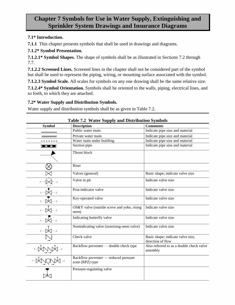
Chapter 7 Symbols for Use in Water Supply, Extinguishing and
Sprinkler System Drawings and Insurance Diagrams
7.1* Introduction.
7.1.1 This chapter presents symbols that shall be used in drawings and diagrams.
7.1.2* Symbol Presentation.
7.1.2.1* Symbol Shapes. The shape of symbols shall be as illustrated in Sections 7.2 through
7.7.
7.1.2.2 Screened Lines. Screened lines in the chapter shall not be considered part of the symbol
but shall be used to represent the piping, wiring, or mounting surface associated with the symbol.
7.1.2.3 Symbol Scale. All scales for symbols on any one drawing shall be the same relative size.
7.1.2.4* Symbol Orientation. Symbols shall be oriented to the walls, piping, electrical lines, and
so forth, to which they are attached.
7.2* Water Supply and Distribution Symbols.
Water supply and distribution symbols shall be as given in Table 7.2.
Table 7.2 Water Supply and Distribution Symbols
Symbol Description Comments
Public water main Indicate pipe size and material
Private water main Indicate pipe size and material
Water main under building Indicate pipe size and material
Suction pipe Indicate pipe size and material
Thrust block
Riser
Valves (general) Basic shape; indicate valve size
Valve in pit Indicate valve size
Post-indicator valve Indicate valve size
Key-operated valve Indicate valve size
OS&Y valve (outside screw and yoke, rising
stem)
Indicate valve size
Indicating butterfly valve Indicate valve size
Nonindicating valve (nonrising-stem valve) Indicate valve size
Check valve Basic shape; indicate valve size,
direction of flow
Backflow preventer — double check type Also referred to as a double check valve
assembly
Backflow preventer — reduced pressure
zone (RPZ) type
Pressure-regulating valve

Pressure relief valve
Float valve
Meter Indicate type
Private hydrant, one hose outlet Indicate size, type of thread, or
connection
Public hydrant, two hose outlets Indicate size, type of thread, or
connection
Public hydrant, two hose outlets and pumper
connection
Indicate size, type of thread, or
connection
Wall hydrant, two hose outlets Indicate size, type of thread, or
connection
Private housed hydrant, two hose outlets Indicate size, type of thread, or
connection
Siamese fire department connection Specify type, size, and angle
Freestanding siamese fire department
connection
Sidewalk or pit type; specify size
Single fire department connection Specify type, size, thread, and angle
Fire pump with drives
Freestanding test header Freestanding; specify number and sizes
of outlets
Wall-mounted test header Wall; specify number and sizes of
outlets
Screen/strainer
7.3 Reserved
7.4 Symbols Related to Means of Egress.
Symbols related to means of egress shall be as given in Table 7.4.
Table 7.4 Symbols Related to Means of Egress
Symbol Description Comments
Emergency light, battery-powered Number of lamps on unit to be
indicated. Indicate whether light
head(s) [lamp(s)] is remote from
battery
Illuminated exit sign, single face Indicate direction of flow for the face
Illuminated exit sign, double face Indicate direction of flow for each face

Combined battery-powered
emergency light and illuminated
exit sign
Number of lamps on unit to be
indicated; indicate whether light
head(s) [lamp(s)] is remote from
battery; indicate direction of flow for
the face
Exit lighting Exit lighting fixture, arrows, and exit
face as indicated on drawings
(mounting heights to be determined by
job specifications) —
from NECA 100, symbol 2.005
Luminaire providing emergency
illumination
(filled in)
From NECA 100, symbol 2.300
Directional sounder — exit
marking audible appliance, wall
mounted
Applied from NECA 100, symbol
9.109
Directional sounder — exit
marking audible appliance, ceiling
mounted
Applied from NECA 100, symbol
9.110
Directional exit indicating strip
lighting appliance
Applied from NECA 100, symbol
2.002
7.5 Symbols for indicating appliances
7.5.1 Indicating Appliances. Symbols for indicating appliances shall be as given in Table 7.5.1.
Table 7.5.1 Symbols for Indicating Appliances
Symbol Description Comments
Water motor alarm
(water motor gong)
Shield optional
7.6* Symbols for Fire Extinguishing Systems.
7.6.1 Various Types of Fire Extinguishing Systems.
7.6.1.1 Water-Based Systems. Symbols for water-based systems shall be as given in Table
7.6.1.1.
Table 7.6.1.1 Symbols for Water-Based Systems
Symbol Description
Wet charged system — automatically
actuated
Wet charged system — manually actuated
Dry system — automatically actuated
Dry system — manually actuated
Foam system — automatically actuated
Foam system — manually actuated
Water mist extinguishing system —
automatically actuated
Water mist extinguishing system —
manually actuated
7.6.1.2 Dry Chemical Systems. Symbols for dry chemical systems shall be as given in Table

7.6.1.2.
Table 7.6.1.2 Symbols for Dry Chemical Systems
Symbol Description
For liquid, gas, and electrical fires —
automatically actuated
For liquid, gas, and electrical fires —
manually actuated
For fires of all types (except metals) —
automatically actuated
For fires of all types (except metals) —
manually actuated
7.6.1.3 Systems Utilizing a Gaseous Medium. Symbols for systems utilizing a gaseous medium
shall be as given in Table 7.6.1.3.
Table 7.6.1.3 Symbols for Systems Utilizing a Gaseous Medium
Symbol Description
Carbon dioxide system — automatically
actuated
Carbon dioxide system — manually actuated
Halon system or clean agent extinguishing
system — automatically actuated
Halon system or clean agent extinguishing
system — manually actuated
7.6.1.4 Supplementary Symbols. Supplementary symbols shall be as given in Table 7.6.1.4.
Table 7.6.1.4 Supplementary Symbols
Symbol Description
Fully sprinklered space
Partially sprinklered space
Nonsprinklered space
Water spray system
7.6.2* Symbols for Fire Sprinklers. Symbols for fire sprinklers shall be as given in Table 7.6.2.
Table 7.6.2 Symbols for Fire Sprinklers
Symbol Description Comments
Upright sprinkler
Pendent sprinkler Note “DP” on drawing and/or in
specifications where dry pendent
sprinklers are employed
Upright sprinkler; on sprig
Upright sprinkler on top of riser nipple

Upright sprinkler on top of riser nipple
with sprig
Pendent sprinkler; on drop nipple Note “DP” on drawing and/or in
specifications where dry pendent
sprinklers are employed
Sprinkler, with guard Upright sprinkler head shown
Sidewall sprinkler
Outside sprinkler Specify type, orifice size; for
example, open sprinkler (window or
cornice)
Open sprinkler on branch line
Open sprinkler on branch line with sprig
Water spray nozzle
Window sprinklers
7.6.3* Symbols for Piping, Valves, Control Devices, and Hangers. Symbols for piping,
valves, control devices, and hangers shall be as given in Table 7.6.3.
Table 7.6.3 Symbols for Piping, Valves, Control Devices, and Hangers
Symbol Description Comments
Sprinkler piping and branch
line
Indicate pipe size
Pipe trace heater See NECA 100, symbol
5.106
Mechanical coupling
Pipe hanger This symbol is a diagonal
stroke imposed on the pipe
that it supports
Lateral brace
Longitudinal brace
Four-way brace Only used to brace risers
Angle valve (angle hose
valve)
Indicate size, type, and
other required data
Check valve (general)
Alarm check valve Specify size, direction of
flow
Dry pipe valve Specify size
Dry pipe valve with quick
opening device (accelerator or
exhauster)
Specify size and type
Deluge valve Specify size and type

Preaction valve Specify size and type
7.4 Symbols for Portable Fire Extinguishers.
Symbols for portable fire extinguishers shall be as given in Table 7.4.
Table 7.4 Symbols for Portable Fire Extinguishers
Symbol Description Comments
Portable fire extinguisher Basic shape
Water extinguisher
Foam extinguisher
Dry chemical extinguisher —
for liquid, gas, or electrical
fires
BC type
Dry chemical extinguisher —
for fires of all types (except
metals)
ABC type
CO2 extinguisher
Halon or
clean agent extinguisher
Extinguisher for metal fires
7.5 Symbols for Fire-Fighting Equipment.
Symbols for fire-fighting equipment shall be as given in Table 7.5.
Table 7.5 Symbols for Fire-Fighting Equipment
Symbol Description Comments
Fire-fighting equipment Basic shape
CO2 reel station
Dry chemical reel station
Foam reel station
Hose station, dry standpipe
Hose station, wet standpipe
Monitor nozzle, dry Specify orifice size
Monitor nozzle, charged Specify orifice size
7.6* Miscellaneous Symbols.
Miscellaneous symbols shall be as given in Table 7.6.
Table 7.6 Miscellaneous Symbols
Symbol Description Comments

Agent storage container Specify type of agent and mounting
Agent storage container — foam
Agent storage container — Halon
Agent storage container — carbon dioxide
Agent storage container — clean agent
Agent storage container — dry chemical
Agent storage container — water mist
Agent storage container — wet chemical
Special spray nozzle Specify type, orifice, size, other required
data (shown here on pipe)
Fusible link Specify degrees
Fusible link with electrothermal feature Specify degrees
Solenoid valve
End of line device — resistor
End of line device — relay
End of line device — capacitor
End of line device — diode
Transfer switch — automatic with handle
Transfer switch — manual with handle

Chapter 8 Symbols for Use in Electronic Fire and Smoke Detection
and Notification System Drawings and Insurance Diagrams
8.1* Introduction.
8.1.1 This chapter presents symbols that shall be used in drawings and diagrams.
8.1.2* Symbol Presentation.
8.1.2.1* Symbol Shapes. The shape of symbols shall be as illustrated in Sections 8.2 through
8.12.
8.1.2.2 Screened Lines. Screened lines in the chapter shall not be considered part of the symbol
but shall be used to represent the piping, wiring, or mounting surface associated with the symbol.
8.1.2.3 Symbol Scale. All scales for symbols on any one drawing shall be the same relative size.
8.1.2.4* Symbol Orientation. Symbols shall be oriented to the walls, piping, electrical lines, and
so forth, to which they are attached.


8.3* Symbols for Fire Alarms, Detection, and Related Equipment.
8.3.1* Signal Initiating Devices and Activation Switches. Symbols for signal initiating devices
and activation switches shall be as given in Table 8.3.1.


8.5 Symbols for Smoke/Pressurization Control.
Symbols for smoke/pressurization controls shall be as given in Table 8.5.
Table 8.5 Symbols for Smoke/Pressurization Control
Symbol Description Comments
Purge controls — manual
control
Hand (manual)/
off-automatic
Fans — general Arrow indicates direction of flow
Fans — duct Arrow indicates direction of flow
Fans — roof Arrow indicates direction of flow
Fans — wall Arrow indicates direction of flow
Dampers — fire
Dampers — smoke
Dampers — fire/smoke
Dampers — motorized
fire/smoke
Dampers — barometric
Pressurized stairwell Orient as required for base or head
injection
Ventilation openings Orient as required for intake or
exhaust

Report on Proposals – November 2011 NFPA 170_______________________________________________________________________________________________170-8 Log #1
_______________________________________________________________________________________________David R. Hague, Liberty Mutual Property
Revise description and comments for fire pump symbol as follows:Description: Fire pump with drives rComments: Specify driver type and rated capacityAdd new symbols for Freestanding test header and wall=-mounted test header as shown in Table 6.4.
***Insert Table 170_L1_Tb 6.4_R Here***
It is important to indicate the type of driver for each fire pump (such as electric, diesel or steam) andindicate on the diagram the rated capacity of the pump. The proposed symbols for the fire pump test header (bothfreestanding and wall-mounted) will more clearly indicate the number of outlets on the diagram.
_______________________________________________________________________________________________170-9 Log #CP6
_______________________________________________________________________________________________Technical Committee on Fire Safety and Emergency Symbols,
Update Table 8.3.2 to match FGDC changes.
***Insert 170_FGDC_changes_R Here***
To keep up to date with changes in the government standard.
_______________________________________________________________________________________________170-10 Log #CP3
_______________________________________________________________________________________________Technical Committee on Fire Safety and Emergency Symbols,
Revise text as follows:The size of text, symbols, and tactile information shall allow visibility by all occupants.
The term "tactile" could be misleading.
3Printed on 9/15/2010

F2011_170_L1_R_Table 6.4
Table 6.4
Symbol Description Comments
Fire pump with drives r. Specify driver type and rated
capacity.
Freestanding test header. Freestanding: specify number
and sizes of outlets.
Wall-mounted test header. Wall: specify number and
sizes of outlets.


Report on Proposals – November 2011 NFPA 170_______________________________________________________________________________________________170-11 Log #CP7
_______________________________________________________________________________________________Technical Committee on Fire Safety and Emergency Symbols,
Revise text as follows:The means of egress from the viewers’ location shall be shown. This shall include all exit locations, exit access
paths, stairways, elevators, elevator lobbies, areas of refuge, areas of rescue assistance, shelter areas, and exterioroutside evacuation assembly areas.
To maintain consistency with government standards.
_______________________________________________________________________________________________170-12 Log #CP5
_______________________________________________________________________________________________Technical Committee on Fire Safety and Emergency Symbols,
Add new text as follows:See Figure A.9.3.
***Insert 170_CP5_Fig A.9.3_R Here***
The new figure provides an example of proper orientation.
_______________________________________________________________________________________________170-13 Log #CP9
_______________________________________________________________________________________________Technical Committee on Fire Safety and Emergency Symbols,
Remove NFPA 170, , 1991 edition and NFPA 172,for D.1.1.
There is no reason to reference an older edition of the standard and NFPA 172 has been incorporatedinto NFPA 170 in previous cycles.
_______________________________________________________________________________________________170-14 Log #CP12
_______________________________________________________________________________________________Technical Committee on Fire Safety and Emergency Symbols,
Update Fire Protection Handbook from 19th edition to 20th edition and update National Fire Codesfrom 2006 edition to 2010 edition.
NFPA Publications should be updated to current editions.
4Printed on 9/15/2010


Report on Proposals – November 2011 NFPA 170_______________________________________________________________________________________________170-15 Log #CP13
_______________________________________________________________________________________________Technical Committee on Fire Safety and Emergency Symbols,
Revise text as follows:ANSI Z535.1 Safety Color Code, 2002 ANSI Z535.1 American National Standard for Safety Colors, 2006.
ANSI Z535.3 Criteria for Safety Symbols, 2002 ANSI Z535.3 American National Standard Criteria for Safety Symbols,2007.ANSI Z535.4 Production Safety Signs and Labels, 2002 ANSI Z535.4 American National Standard for Product Safety
Signs and Labels, 2007.The current editions should be referenced.
_______________________________________________________________________________________________170-16 Log #CP15
_______________________________________________________________________________________________Technical Committee on Fire Safety and Emergency Symbols,
Delete D.2.3.Referenced publication is no longer published or referenced in NFPA 170.
_______________________________________________________________________________________________170-17 Log #CP16
_______________________________________________________________________________________________Technical Committee on Fire Safety and Emergency Symbols,
Delete ISO 3461-1976 from D.2.4.ISO 3461-1976 has been withdrawn by ISO.
5Printed on 9/15/2010