
Robust Control Framework for Time-Varying Power...
8
Robust Control Framework for Time-Varying Power-Sharing among Distributed Energy Resources Mayank Baranwal 1,a and Srinivasa M. Salapaka 1,b Abstract— One of the most important challenges facing an electric grid is to incorporate renewables and distributed energy resources (DERs) to the grid. Because of the associated uncertainties in power generations and peak power demands, opportunities for improving the functioning and reliability of the grid lie in the design of an efficient, yet pragmatic distributed control framework with guaranteed robustness margins. This paper addresses the problem of output voltage regulation for multiple DC-DC converters connected to a grid, and prescribes a robust scheme for sharing power among different sources. More precisely, we develop a control archi- tecture where, unlike most standard control frameworks, the desired power ratios appear as reference signals to individual converter systems, and not as internal parameters of the system of parallel converters. This makes the proposed approach suited for scenarios when the desired power ratios vary rapidly with time. Additionally, the proposed control framework is suitable to both centralized and decentralized implementations, i.e., the same control architecture can be employed for voltage regulation irrespective of the availability of common load- current (or power) measurement, without the need to modify controller parameters. The control design is obtained using robust optimal-control framework. Case studies presented show the enhanced performance of prescribed optimal controllers for voltage regulation and power sharing. I. INTRODUCTION High environmental impact of fossil-based energy sources and demand for future energy sustainability have resulted in increased interest in the use of renewable energy resources such as solar and wind. Integration of renewable resources on the community level is achieved through smart microgrids. Microgrids are localized grid systems that are capable of operating in parallel with, or independently from, the exist- ing traditional grid [1], [2]. Microgrid technology enables integration of renewable energy sources such as solar and wind energy, distributed energy resources (DERs), energy storage, and demand response. Fig. 1 shows a schematic of a microgrid with multiple DC sources providing power for AC loads. Although in most traditional grids that rely on conventional sources of dispatchable electric power, the power output of renewables can not be manipulated. Limited predictability with such resources result in intermittent power generation; moreover time-varying loads, practicability and economics factors pose additional challenges in efficient operation of microgrids. Thus it is required to develop effi- cient distributed control technologies for reliable operation of smart microgrids. 1 Department of Mechanical Science and Engineering, University of Illinois at Urbana-Champaign, 61801 IL, USA a [email protected], b [email protected] Fig. 1: A schematic of a microgrid. An array of DC sources provide power for AC loads. Power sources provide power at DC-link, their common output bus, at a voltage that is regulated to a set- point. The control system at the respective DC-DC converter that interfaces with a source is responsible for regulating the voltage at he DC-link. An inverter that connects to the DC-link converts the total current from the sources at the regulated voltage to alternating current (AC) at its output to satisfy the power demands of the AC loads. This paper describes an approach for control design of the multiple converters systems associated with power transfer from sources to the DC-link (shown by the dotted line). In such smart grids, multiple DC power sources connected in parallel, each interfaced with DC-DC converter, provide power at their common output, the DC-link, at a regulated voltage; this power can directly feed DC loads or be used by an inverter to interface with AC loads. In this paper, we ad- dress the problem of distributed control of DC-DC converters for output voltage regulation, and time-varying power sharing (dictated by the economic layer) among multiple power sources. The main challenges arise from the uncertainties in the size and the schedules of loads, the complexity of a coupled multi-converter network, the uncertainties in the model parameters at each converter, and the adverse effects of interfacing DC power sources with AC loads, such as the 120 Hz ripple that has to be provided by the DC sources. Problems pertaining to robust and optimal control of converters have received recent attention. Conventional PID- based controllers often to fail address the problem of ro- bustness and modeling uncertainties. In [3], a linear-matrix- inequality (LMI) based based robust control design for boost converters has resulted in significant improvements over PID based control designs. In [4]–[6], robust H ∞ -control frame- work is employed in the context of inverter systems. While the issue of current sharing is extensively studied [7], [8], most methods assume a single power source. A systematic arXiv:1604.04154v1 [math.OC] 14 Apr 2016
Transcript of Robust Control Framework for Time-Varying Power...
Robust Control Framework for Time-Varying Power-Sharing amongDistributed Energy Resources
Mayank Baranwal1,a and Srinivasa M. Salapaka1,b
Abstract— One of the most important challenges facing anelectric grid is to incorporate renewables and distributedenergy resources (DERs) to the grid. Because of the associateduncertainties in power generations and peak power demands,opportunities for improving the functioning and reliabilityof the grid lie in the design of an efficient, yet pragmaticdistributed control framework with guaranteed robustnessmargins. This paper addresses the problem of output voltageregulation for multiple DC-DC converters connected to a grid,and prescribes a robust scheme for sharing power amongdifferent sources. More precisely, we develop a control archi-tecture where, unlike most standard control frameworks, thedesired power ratios appear as reference signals to individualconverter systems, and not as internal parameters of the systemof parallel converters. This makes the proposed approach suitedfor scenarios when the desired power ratios vary rapidly withtime. Additionally, the proposed control framework is suitableto both centralized and decentralized implementations, i.e.,the same control architecture can be employed for voltageregulation irrespective of the availability of common load-current (or power) measurement, without the need to modifycontroller parameters. The control design is obtained usingrobust optimal-control framework. Case studies presented showthe enhanced performance of prescribed optimal controllers forvoltage regulation and power sharing.
I. INTRODUCTION
High environmental impact of fossil-based energy sourcesand demand for future energy sustainability have resulted inincreased interest in the use of renewable energy resourcessuch as solar and wind. Integration of renewable resources onthe community level is achieved through smart microgrids.Microgrids are localized grid systems that are capable ofoperating in parallel with, or independently from, the exist-ing traditional grid [1], [2]. Microgrid technology enablesintegration of renewable energy sources such as solar andwind energy, distributed energy resources (DERs), energystorage, and demand response. Fig. 1 shows a schematicof a microgrid with multiple DC sources providing powerfor AC loads. Although in most traditional grids that relyon conventional sources of dispatchable electric power, thepower output of renewables can not be manipulated. Limitedpredictability with such resources result in intermittent powergeneration; moreover time-varying loads, practicability andeconomics factors pose additional challenges in efficientoperation of microgrids. Thus it is required to develop effi-cient distributed control technologies for reliable operationof smart microgrids.
1Department of Mechanical Science and Engineering, University ofIllinois at Urbana-Champaign, 61801 IL, USA
[email protected], [email protected]
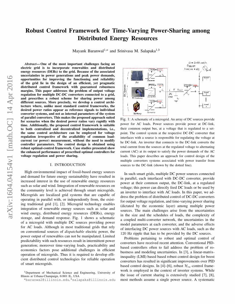
Fig. 1: A schematic of a microgrid. An array of DC sources providepower for AC loads. Power sources provide power at DC-link,their common output bus, at a voltage that is regulated to a set-point. The control system at the respective DC-DC converter thatinterfaces with a source is responsible for regulating the voltage athe DC-link. An inverter that connects to the DC-link converts thetotal current from the sources at the regulated voltage to alternatingcurrent (AC) at its output to satisfy the power demands of the ACloads. This paper describes an approach for control design of themultiple converters systems associated with power transfer fromsources to the DC-link (shown by the dotted line).
In such smart grids, multiple DC power sources connectedin parallel, each interfaced with DC-DC converter, providepower at their common output, the DC-link, at a regulatedvoltage; this power can directly feed DC loads or be used byan inverter to interface with AC loads. In this paper, we ad-dress the problem of distributed control of DC-DC convertersfor output voltage regulation, and time-varying power sharing(dictated by the economic layer) among multiple powersources. The main challenges arise from the uncertaintiesin the size and the schedules of loads, the complexity ofa coupled multi-converter network, the uncertainties in themodel parameters at each converter, and the adverse effectsof interfacing DC power sources with AC loads, such as the120 Hz ripple that has to be provided by the DC sources.
Problems pertaining to robust and optimal control ofconverters have received recent attention. Conventional PID-based controllers often to fail address the problem of ro-bustness and modeling uncertainties. In [3], a linear-matrix-inequality (LMI) based based robust control design for boostconverters has resulted in significant improvements over PIDbased control designs. In [4]–[6], robust H∞-control frame-work is employed in the context of inverter systems. Whilethe issue of current sharing is extensively studied [7], [8],most methods assume a single power source. A systematic
arX
iv:1
604.
0415
4v1
[m
ath.
OC
] 1
4 A
pr 2
016

control design that addresses all the challenges and objectivesfor the multi-converter control is still lacking. The controlarchitecture proposed in this paper addresses the followingprimary objectives - 1) voltage regulation at the DC-link withguaranteed robustness margins, 2) prescribed time-varyingpower sharing in a network of parallel converters, 3) control-ling the trade-off between 120Hz ripple on the total currentprovided by the power sources and the ripple on the DC-linkvoltage. While these objectives are partially addressed in ourprior work [9] on the robust control of DC-DC converters,a main drawback of the design proposed in [9] is that thecontrol framework does not allow for time-varying powersharing requirements. In this work, we propose a novelcontrol framework wherein the power requirements on eachconverter are imposed through external references, and thusthe framework allows for time-varying power sharing byincorporating high-bandwidth robust controllers.
The control architecture proposed in this work exploitsstructural features of the paralleled multi-converter system,which results in a modular and yet coordinated controldesign. For instance, noting that the objective of voltageregulation is common to all converters; accordingly at eachconverter, it employs a nested (outer-voltage inner-current)control structure [10], where all converters share the samedesign for the outer-loop voltage controllers while the inner-loop current controllers are so chosen that the entire closed-loop multi-converter system can be reduced to an equivalentsingle-converter system in terms of the transfer function fromthe desired regulation setpoint Vref to the voltage at theDC-link Vdc. The controllers are designed for fully cen-tralized implementation with the instantaneous load currentiload measurement accessible to all converters; however, inpractice iload is often estimated through power calculationson the AC side and communicated to individual convertersonly at a rate slower than the sampling rate of the controllers.In the wake of this limitation, we propose a novel method forvoltage regulation and power sharing that is inspired by con-ventional voltage droop method. An interesting aspect of theproposed implementation is that the same outer controllersKv and Kr along with the shaped inner plant Gc,n can beemployed even for the scenario where iload measurementis unavailable. Thus the proposed framework is applicableto both centralized and decentralized implementations. Animportant revelation provided by the application of H∞robust optimal control is the underlying optimal structurein the outer-loop controllers Kv and Kr. While we are yetto explore the reasoning behind the hidden optimal structure,it helps in further reduction of the overall complexity of thedistributed control design from analysis and implementationpoints of view.
The rest of the paper is organized as follows. Sec. IIdescribes the averaged modeling of DC-DC converters. Wethen describe the control design methodology for a singleconverter system in Sec. IV, followed by its extension toa network of parallel converters in Sec. V. The underlyingtheory is then corroborated by extensive simulations in Sec.VI, followed by some important conclusions and immediate
(a)
(b)
Fig. 2: Schematics for (a) Buck converter, (b) Boost Converter. Theconverters are assumed to operate in continuous-conduction-mode(CCM).
directions to future works.
II. MODELING OF CONVERTERS
In this section, we describe the differential equations thatgovern the dynamics of DC-DC converters. These convertersbelong to a class of switched-mode power electronics, wherea semiconductor based high-frequency switching mechanism(and associated electronic circuit) connected to a DC powersource enables changing voltage and current characteristicsat its output. The models presented below depict dynamicsfor signals that are averaged over a switch cycle.
Fig. 2a shows a schematic of a Buck converter. Buckconverter regulates a voltage at its output which is lowerthan the input voltage. The averaged dynamic model of aBuck converter is given by
LdiL(t)
dt= −V (t) + d(t)Vg︸ ︷︷ ︸
u(t):=−V (t)+u(t)
= u(t)
CdV (t)
dt= iL(t)− iload(t), (1)
where d(t) represents the duty-cycle (or the proportion ofON duration) at time t. Note that the prescribed averagedmodel does not explicitly require any information on theoutput load.
Similarly we can describe the averaged dynamics of aBoost converter (shown in Fig. 2b), given by
LdiL(t)
dt= Vg − d′(t)V (t)︸ ︷︷ ︸
u(t):=Vg−u(t)
= u(t)
CdV (t)
dt=(D′ + d′
)︸ ︷︷ ︸≈D′
iL(t)− iload(t) ≈ D′iL(t)− iload(t), (2)
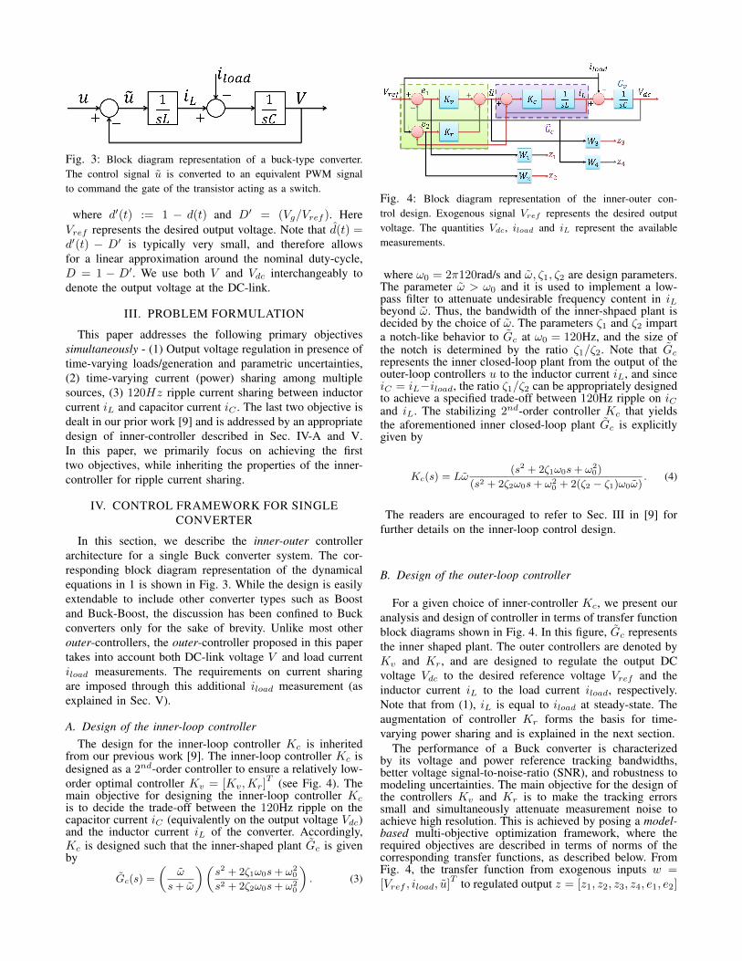
Fig. 3: Block diagram representation of a buck-type converter.The control signal u is converted to an equivalent PWM signalto command the gate of the transistor acting as a switch.
where d′(t) := 1 − d(t) and D′ = (Vg/Vref ). HereVref represents the desired output voltage. Note that d(t) =d′(t) − D′ is typically very small, and therefore allowsfor a linear approximation around the nominal duty-cycle,D = 1 − D′. We use both V and Vdc interchangeably todenote the output voltage at the DC-link.
III. PROBLEM FORMULATION
This paper addresses the following primary objectivessimultaneously - (1) Output voltage regulation in presence oftime-varying loads/generation and parametric uncertainties,(2) time-varying current (power) sharing among multiplesources, (3) 120Hz ripple current sharing between inductorcurrent iL and capacitor current iC . The last two objective isdealt in our prior work [9] and is addressed by an appropriatedesign of inner-controller described in Sec. IV-A and V.In this paper, we primarily focus on achieving the firsttwo objectives, while inheriting the properties of the inner-controller for ripple current sharing.
IV. CONTROL FRAMEWORK FOR SINGLECONVERTER
In this section, we describe the inner-outer controllerarchitecture for a single Buck converter system. The cor-responding block diagram representation of the dynamicalequations in 1 is shown in Fig. 3. While the design is easilyextendable to include other converter types such as Boostand Buck-Boost, the discussion has been confined to Buckconverters only for the sake of brevity. Unlike most otherouter-controllers, the outer-controller proposed in this papertakes into account both DC-link voltage V and load currentiload measurements. The requirements on current sharingare imposed through this additional iload measurement (asexplained in Sec. V).
A. Design of the inner-loop controllerThe design for the inner-loop controller Kc is inherited
from our previous work [9]. The inner-loop controller Kc isdesigned as a 2nd-order controller to ensure a relatively low-order optimal controller Kv = [Kv,Kr]
T (see Fig. 4). Themain objective for designing the inner-loop controller Kcis to decide the trade-off between the 120Hz ripple on thecapacitor current iC (equivalently on the output voltage Vdc)and the inductor current iL of the converter. Accordingly,Kc is designed such that the inner-shaped plant Gc is givenby
Gc(s) =
(ω
s+ ω
)(s2 + 2ζ1ω0s+ ω2
0
s2 + 2ζ2ω0s+ ω20
). (3)
Fig. 4: Block diagram representation of the inner-outer con-trol design. Exogenous signal Vref represents the desired outputvoltage. The quantities Vdc, iload and iL represent the availablemeasurements.
where ω0 = 2π120rad/s and ω, ζ1, ζ2 are design parameters.The parameter ω > ω0 and it is used to implement a low-pass filter to attenuate undesirable frequency content in iLbeyond ω. Thus, the bandwidth of the inner-shpaed plant isdecided by the choice of ω. The parameters ζ1 and ζ2 imparta notch-like behavior to Gc at ω0 = 120Hz, and the size ofthe notch is determined by the ratio ζ1/ζ2. Note that Gcrepresents the inner closed-loop plant from the output of theouter-loop controllers u to the inductor current iL, and sinceiC = iL−iload, the ratio ζ1/ζ2 can be appropriately designedto achieve a specified trade-off between 120Hz ripple on iCand iL. The stabilizing 2nd-order controller Kc that yieldsthe aforementioned inner closed-loop plant Gc is explicitlygiven by
Kc(s) = Lω(s2 + 2ζ1ω0s+ ω2
0)
(s2 + 2ζ2ω0s+ ω20 + 2(ζ2 − ζ1)ω0ω)
. (4)
The readers are encouraged to refer to Sec. III in [9] forfurther details on the inner-loop control design.
B. Design of the outer-loop controller
For a given choice of inner-controller Kc, we present ouranalysis and design of controller in terms of transfer functionblock diagrams shown in Fig. 4. In this figure, Gc representsthe inner shaped plant. The outer controllers are denoted byKv and Kr, and are designed to regulate the output DCvoltage Vdc to the desired reference voltage Vref and theinductor current iL to the load current iload, respectively.Note that from (1), iL is equal to iload at steady-state. Theaugmentation of controller Kr forms the basis for time-varying power sharing and is explained in the next section.
The performance of a Buck converter is characterizedby its voltage and power reference tracking bandwidths,better voltage signal-to-noise-ratio (SNR), and robustness tomodeling uncertainties. The main objective for the design ofthe controllers Kv and Kr is to make the tracking errorssmall and simultaneously attenuate measurement noise toachieve high resolution. This is achieved by posing a model-based multi-objective optimization framework, where therequired objectives are described in terms of norms of thecorresponding transfer functions, as described below. FromFig. 4, the transfer function from exogenous inputs w =[Vref , iload, u]
T to regulated output z = [z1, z2, z3, z4, e1, e2]

is given byz1z2z3z4e1e2
=
W1 W1Gv −W1GvGc
0 W2 −W2Gc
0 0 W3
0 −W4Gv W4GvGc
1 Gv −GvGc
0 1 −Gc
Vref
iloadu
. (5)
The optimization problem is to find stabilizing controllersKouter = [Kv,Kr]
T such that the H∞-norm of the abovetransfer function from w to z is minimized. Here the weightsW1,W2,W3 and W4 are chosen to reflect the design spec-ifications of robustness to parametric uncertainties, trackingbandwidth, and saturation limits on the control signal. Morespecifically, the weight functions W1(jω) and W2(jω) arechosen to be large in frequency range [0, ωBW ] to ensuresmall tracking errors e1 = Vref − Vdc and e2 = iload − iLin this frequency range. The design of weight functionW3(jω) entails ensuring that the control effort lies withinsaturation limits. The weight function W4 is designed as ahigh-pass filter to ensure that the transfer function from iloadto Vdc is small at high frequencies to provide mitigation tomeasurement noise.
Current droop compensation for voltage regulation with-out iload measurement: So far in our analysis, we assume thatiload is available for direct measurement for all converters.However in practice, while the converters can measure theircommon DC-link voltage Vdc, iload is only estimated throughpower calculations on the AC side and communicated to indi-vidual converters only at a rate slower than the sampling rateof the controllers. In the wake of this limitation, we proposea novel method for voltage regulation and power sharingthat is inspired by conventional voltage droop method. Aninteresting aspect of the proposed implementation is that thesame outer controllers Kv and Kr along with the shapedinner plant Gc,n can be employed even for the scenariowhere iload measurement is unavailable. In this case, theouter controller Kr regulates the inductor current iL toiref +f(·)∗ (Vref −Vdc), where f(·) represents an LTI filterand ∗ is the convolution operator. This can be understoodas follows. Let us suppose that iref > iload = (Vref/R),where R is the output load resistance. This in turn impliesthat Vdc = irefR is bigger than Vref . Thus the compensationterm (Vref − Vdc) < 0 and the reference to the outer-loop controller Kr becomes smaller than iref , as required.A similar inference can be drawn when iref < iload. Thecorresponding block diagram is shown in Fig. 5.
Extension to Boost Converters: The extension of theproposed control design to Boost and Buck-Boost DC-DCconverters is easily explained after noting that their averagedmodels are structurally identical to Buck converters, exceptthat the dependence of duty cycles on the control signal uor constant parameter D′ are different. The differences inhow duty cycles depend on u(t) do not matter from thecontrol design viewpoint since duty cycles for pulse-widthmodulation are obtained only after obtaining the controldesigns (that use the averaged models). Fig. 6 shows the
Fig. 5: Modified architecture for decentralized implementation.F (s) represents the Laplace transform of the corresponding LTIfilter f(·). The reference to the outer controller Kr is iref + f(·)∗(Vref − Vdc).
Fig. 6: Block diagram representation of the inner-outer controldesign for boost-converter. Note that this representation differs fromthat of the buck converter only in terms of the constant parameterD′ and the expression that is used to obtain the duty-cycle fromthe control signal u.
equivalent schematic of the proposed control framework fora Boost converter system.
V. EXTENSION TO A SYSTEM OF PARALLELCONVERTERS
In this section we extend our control framework for asingle converter to a system of DC-DC converters connectedin parallel in the context of power sharing, keeping inmind the practicability and robustness to modeling and loaduncertainties.
Fig. 7a represents an inner-outer control framework for asystem of m parallel connected converters. Note that insteadof feeding iload directly to the kth outer controller Krk , themeasurement signal is prescaled by a time-varying multiplierγk, 0 ≤ γk ≤ 1. The choice of γk dictates the power sharingrequirements on the kth converter. In fact, we later show thatthe proposed implementation distributes the output power inthe ratios γ1 : γ2 : .. : γm. After noting that the voltage-regulation and current reference tracking is common to allthe outer controllers, in our architecture, we impose thesame design for outer-controllers for all the converters, i.e.,Kv1 = Kv2 = .. = Kvm and Kr1 = Kr2 = .. = Krm .This imposition enables significant reduction in the overallcomplexity of the distributed control design for a parallelnetwork of converters and power sources, thus ensuring thepracticability of the proposed design which allows integrationof power sources of different types and values.
We design inner-controllers Kck such that the inner-shapedplants from uk to iLk
are same and given by,
Gc,n(s) =
(ω
s+ ω
)(s2 + 2ζ1,nω0s+ ω2
0
s2 + 2ζ2,nω0s+ ω20
), (6)

(a) (b)Fig. 7: (a) Control framework for a network of m parallel converters. Here γk represents the proportion of power demanded from thekth source. (b) A multiple-converters system with shaped inner plants Gc. In the proposed implementation, we adopt the same outercontroller for different converters, i.e., Kv1 = Kv2 = .. = Kvm = 1
mKv and Kr1 = Kr2 = .. = Krm = Kr .
where the ratio ζ1,n/ζ2,n determines the tradeoff of 120Hz
ripple between the total inductor current iL =m∑k=1
iLk
and the capacitor current iC . Note that for given values ofζ1,n, ζ2,n and inductance Lk, explicit design of Kck existsand is given by (4). After noting that Kvk = 1
mKv andKrk = Kr, the system in Fig. 7a can be simplified to Fig.7b.
Indeed, by our choice of inner and outer controllers, thetransfer functions from external references Vref and ikref tothe desired output Vdc are identical for all converters. Hencethe entire network of parallel converters can be analyzed inthe context of an equivalent single converter system. Thisimplies that Kvk and Krk can be computed by solving H∞-optimization problem (as discussed in the previous section)similar to the single converter case. We make these designspecifications more precise and bring out the equivalenceof the control design for the single and multiple convertersystems in the following theorem.
We say that the system representation in Fig. 4 is equiva-lent to that in Fig. 7b, when the transfer functions from thereference voltage Vref and load current iload to the DC-link voltage Vdc (and therefore the total current sourcedi = iL) in Fig. 4 are identical to the correspondingtransfer functions in Fig. 7b. In the following theorem, wedenote the outer-voltage sensitivity transfer function in Fig.4 from Vref to Vdc by S1 =
(1
1+Gc,nKr+GvGc,nKv
)and the
corresponding complementary sensitivity transfer functionby T1 = GvGc,nKvS1. Similarly, we denote the outer-current sensitivity transfer function by S2 =
(1
1+Gc,nKr
)and the corresponding complementary transfer function byT2 = 1− S2. Moreover, we define H = Gc,nKvS1.
Theorem 1: Consider the single-converter system in Fig-ure 4 with inner-shaped plant Gc,n(s) as given in (6), outercontrollers Kv , Kr and external references Vref , iload; andthe multi-converter system described in Figures 7a and 7b
with inner-shaped plants Gck = Gc,n(s) and outer con-trollers Kvk = 1
mKv; Krk = Kr, and external referencesVref , ikref for 1 ≤ k ≤ m.1. [System Equivalence]: If
∑mk=1 ikref = iload, then the
system representations in Fig. 4 and Fig. 7b are equivalent.2. [Power Sharing]: If controllers Kv and Kr are designedsuch that |H(jω)| < ε, |S2(jω)| < ε and the total currentmismatch |
∑k ikref (jω) − iload(jω)| < ∆ at frequncy ω
for some ε > 0 and ∆ > 0, then |iLk(jω) − ikref (jω)| <
ε(|Vref (jω)|+m|ikref(jω)|+(1+ε)|iload(jω)|)m + (1+ε)2∆
m .Remark 1: Since the system representations in Figs. 4 and7b are equivalent, the analysis and design of the entire multi-converter system can be done using an equivalent singleconverter system, where the multi-converter system inheritsthe performance and robustness achieved by a design for thesingle-converter system.Remark 2: While the sensitivity transfer functions S1 andS2 can be made sufficiently small by designing appropriatehigh DC-gain controllers, the transfer function H is alsosmall at sufficiently low-frequencies. In fact, it can be easilyshown that |H(j0)| = 0, since |Gc,n(j0)| = 1 and Gv(s) =1/(sC), which has infinite DC-gain.Remark 3: Note that from power-sharing result in the abovetheorem, if ikref = γkiload, where
∑k γk = 1, γk ≥ 0, then
the output current at the DC-link gets divided approximatelyin the ratio γ1 : γ2 : · · · : γm; more precisely the low-frequency components (and thus the steady-state) iL1
: iL2:
· · · : iLm≈ γ1 : γ2 : · · · : γm.
Proof: See Appendix.
VI. CASE STUDIES: SIMULATIONS ANDDISCUSSIONS
In this section, we report some simulation studies thatcover different aspects of the proposed distributed controldesign. All simulations are performed in MATLAB/Simulinkusing SimPower/SimElectronics library. Note that the exper-iments are underway and therefore not reported in this paper.

In order to include nonlinearities associated with real-worldexperiments, and effects of switching frequencies on voltageregulation and power sharing, we use non-ideal components(such as diodes with non-zero forward-bias voltage, IGBTswitches, stray capacitances, parametric uncertainties) andswitched level implementation.
A. Robustness to Modeling Parameters
Traditional control techniques such as proportional-integral (PI) based control designs exhibit satisfactory perfor-mance when the actual converter system parameters (L,C)lie close to the nominal system parameters for which thecontrollers are to be designed. A slight deviation fromthe nominal values may result in rapid degradation in thetracking performance and power sharing. The issue is partic-ularly critical in power electronic systems where individualcomponent values have large tolerance about the nominalvalues. The lack of robustness is addressed through H∞ ro-bust control framework, where an optimizing controller withguaranteed margins of robustness to modeling uncertaintiesis sought.
Fig. 8a shows the tracking performance of the proposedrobust inner-outer controllers for 20% uncertainty in indcu-tance (L) and capacitance (C) values. The actual converterparameters are chosen as:C = 500µF, L = 1.2mH, Switching-frequency fs = 50kHz,Input voltage Vg = 480V , Desired output voltage Vref =240V , Load-current iload = 20 + 0.4 sin(2π120t)The design parameters for the inner-controller Kc are:Damping factors ζ1 = 1.2, ζ2 = 2.1, and ω = 2π200rad/s.The outer controllers Kv and Kr are obtained by solving thestacked H∞ optimization problem (see Eq. (5)) [11] with theweighting functions:
W1 =0.5(s+ 502.7)
(s+ 2.513),W2 =
0.5(s+ 628.3)
(s+ 3.142),W3 = 0.1
The resulting outer-controllers are reduced to sixth-orderusing balanced reduction [12] and are given by,
Kv = −0.0076(s− 8.69e5)
(s+ 2.73e4)
(s+ 2.01e4)
(s+ 1.07e4)
(s+ 2577)
(s+ 433.9)
(s+ 194.2)
(s+ 2.498)
(s2 + 0.02s+ 0.0001)
(s2 + 0.01978s+ 0.0008)
Kr = 0.065(s+ 4.07e5)
(s+ 1.15e4)
(s+ 2474)
(s+ 422.4)
(s+ 191.7)
(s+ 3.11)
(s+ 3.20)
(s+ 2.03)
(s+ 0.01)(s+ 0.0099)
(s2 + 0.01978s+ 0.0008)
Optimal structure of outer-loop controllers: For thestacked H∞ problem, the outer-loop controllers Kv andKr are observed to be constant multiples of each other fora number of choices of weighting functions W1 and W2.While we are yet to explore the reasons for the underlyingoptimal structure, the optimal structure significantly reducesthe complexity of the distributed control design by allowingto get rid of the controller Kr from the outer-loop andmodifying the input of the controller Kv to Vref − Vdc +α(iload − iL). Here α > 0 is an appropriate constant whichcaptures the relationship between the outer-loop controllersKv and Kr. We believe that the constant α is related to the
Fig. 9: Power sharing among three buck-converters for Vref =
240V and R = 12Ω in the prescribed ratios. The controllers allowfor rapidly varying power-sharing requirements.
system parameters L and C, however, this is something wewould definitely like to explore in our future work.
B. Current Sharing among Converters
Fig. 9 shows the system performance for time-varyingoutput current sharing among three Buck converters. Thefollowing parameters are assumed for the three converters- L1 = 1.2mH, Vg1 = 480V ; L2 = 1.6mH, Vg2 = 460V ;L3 = 1.9mH, Vg3 = 480V . Clearly, the total load currentis 20A. The converters divide the load current in the ratios10 : 4 : 6 for t ∈ [0, 0.3s]; 4 : 8 : 8 for t ∈ [0.3s, 0.5s] and6 : 4 : 10 for t ∈ [0.5s, 0.6s], as required.
C. Current Sharing and Voltage Regulation without iloadmeasurement
We now consider the scenario when iload measurementis unavailable. In this case, the input to the outer-loopcontroller Kr is some nominal reference current iref plus acompensation term which is a manifestation of error in volt-age reference tracking. This can be understood as follows.Fig. 10 shows the system performance for voltage referencetracking for the proposed decentralized implementation. Notethat despite the unavailability of load current measurement,the controller regulates the DC-link voltage to the desiredreference voltage, albeit with relatively larger overshoot.
VII. CONCLUSIONS AND FUTURE WORKS
In this work, we propose a distributed control architec-ture for voltage tracking and power sharing for a networkof DC-DC converters connected in parallel. The proposeddesign is capable of achieving multiple objectives such asrobustness to modeling uncertainties, reference DC voltagegeneration and output power sharing among multiple DCsources. The controllers are designed using a robust optimalcontrol framework. We also propose a novel approach fordecentralized implementation, where the load current is notavailable for measurement. We are currently setting up theexperiments to demonstrate the effectiveness of the proposedimplementation. Moreover, the optimal structure of the outer-loop controllers Kv and Kr needs to be analyzed in fulldetails to gain further insights into the problem of voltagecontrol of DC-DC converters.

(a) (b)Fig. 8: (a) Robustness to model parameters. The proposed controller tracks the desired voltage in presence of parametric uncertaintiesand ripple in load current. (b) Bode plots of the outer-loop controllers. It can be observed that the two controller transfer functions areconstant multiples of one-another.
Fig. 10: A droop-like approach for voltage regulation in theabsence of iload measurement. The converter is required to regulatethe output voltage to 240V . The load R is chosen to be 12Ω. Thiscorresponds to an iload = 20A. However, in the absence of iloadmeasurement, we assume iref = 16A. The filter transfer functionis chosen as F (s) = 376.99
s+314.16.
APPENDIX
Proof of Theorem 1: System Equivalence
Proof: The underlying equivalence is straightforwardto derive. From Fig. 4, with Gc(s) = Gc,n(s), the outputDC-link voltage in terms of the exogenous signals Vref andiload is given by
Vdc =
(1
1+Gc,nKr+GvGc,nKv
)(GvGc,nKvVref −Gviload
)(7)
However, from Figs. 7a and 7b, we obtain
Vdc = Gv
(−iload + Gc,n
m∑k=1
uk
)
uk =
(1
1 + Gc,nKr
)(1
mKv(Vref − Vdc) +Krikref
)(8)
From Eq. (8) and using the fact that∑mk=1 ikref = iload we
recover Eq. (7), which establishes the required equivalence.
Proof of Theorem 1: Power Sharing
Proof: From Fig. 8b, it can be shown that the differencebetween the inductor current iLk
and the reference current
ikref for the kth converter (in terms of signals Vref , iloadand ikref ) is given by
iLk − ikref =1
mHVref −
1
mT1T2
(∑k
ikref − iload
)+
1
mT1S2iload − S2ikref (9)
Moreover, we have |T1(jω)| < 1 + ε and |T2(jω)| < 1 + ε.Thus from (9) and conditions of the theorem, we get
|iLk (jω)− ikref (jω)| < ε
m|Vref (jω)|+ ε(1 + ε)
m|iload(jω)|
+(1 + ε)2∆
m+ ε|ikref (jω)| (10)
Additionally, if ikref = γkiload, then the total current mis-match term in (9) is zero. Moreover, through an appropriatedesign of high DC-gain controllers, we have that there existsa sufficiently small ε > 0 such that for ω << ωBW , whereωBW is bandwidth of the closed-loop system, |H(jω)| < εand |S2(jω)| < ε. Then from (10) we obtain,
|iLk (jω)−γkiload(jω)| < ε
m|Vref (jω)|+ ε
m|iload(jω)|
+ε|ikref (jω)| (11)
Thus |iLk(jω)−γkiload(jω)| is small for ω << ωBW and
therefore, the load current gets approximately divided in theratio γ1 : γ2 : · · · : γm.
REFERENCES
[1] R. H. Lasseter, “Microgrids,” in Power Engineering Society WinterMeeting, 2002. IEEE, vol. 1. IEEE, 2002, pp. 305–308.
[2] N. Hatziargyriou, H. Asano, R. Iravani, and C. Marnay, “Microgrids,”Power and Energy Magazine, IEEE, vol. 5, no. 4, pp. 78–94, 2007.
[3] C. Olalla, R. Leyva, A. El Aroudi, P. Garces, and I. Queinnec,“Lmi robust control design for boost pwm converters,” IET PowerElectronics, vol. 3, no. 1, pp. 75–85, 2010.
[4] G. Weiss, Q.-C. Zhong, T. C. Green, and J. Liang, “H repetitivecontrol of dc-ac converters in microgrids,” Power Electronics, IEEETransactions on, vol. 19, no. 1, pp. 219–230, 2004.
[5] T. Hornik and Q.-C. Zhong, “A current-control strategy for voltage-source inverters in microgrids based on and repetitive control,” PowerElectronics, IEEE Transactions on, vol. 26, no. 3, pp. 943–952, 2011.
[6] S. Salapaka, B. Johnson, B. Lundstrom, S. Kim, S. Collyer, andM. Salapaka, “Viability and analysis of implementing only voltage-power droop for parallel inverter systems,” in Decision and Control(CDC), 2014 IEEE 53rd Annual Conference on. IEEE, 2014, pp.3246–3251.

[7] Y. Panov, J. Rajagopalan, and F. C. Lee, “Analysis and designof n paralleled dc-dc converters with master-slave current-sharingcontrol,” in Applied Power Electronics Conference and Exposition,1997. APEC’97 Conference Proceedings 1997., Twelfth Annual, vol. 1.IEEE, 1997, pp. 436–442.
[8] R.-H. Wu, T. Kohama, Y. Kodera, T. Ninomiya, and F. Ihara, “Load-current-sharing control for parallel operation of dc-to-dc converters,”in Power Electronics Specialists Conference, 1993. PESC’93 Record.,24th Annual IEEE. IEEE, 1993, pp. 101–107.
[9] M. Baranwal, S. M. Salapaka, and M. V. Salapaka, “Robust de-centralized voltage control of dc-dc converters with applications topower sharing and ripple sharing,” in American Control Conference(ACC), 2016 - To Appear. IEEE, 2016, http://web.engr.illinois.edu/∼baranwa2/ACC2016/2016ACC 1392 FI.pdf.
[10] R. W. Erickson and D. Maksimovic, Fundamentals of power electron-ics. Springer Science & Business Media, 2007.
[11] S. Skogestad and I. Postlethwaite, Multivariable feedback control:analysis and design. Wiley New York, 2007, vol. 2.
[12] G. E. Dullerud and F. Paganini, A course in robust control theory: aconvex approach. Springer Science & Business Media, 2013, vol. 36.


![[11] Robust Identification and Control With Time-Varying Parameter Perturbations_2004](https://static.fdocuments.in/doc/165x107/577cdf841a28ab9e78b16a08/11-robust-identification-and-control-with-time-varying-parameter-perturbations2004.jpg)


