Robust ANFIS Vector Control of Induction Motor Drive for ...
10
Robust ANFIS Vector Control of Induction Motor Drive for High-Performance Speed Control Supplied by a Photovoltaic Generator Abstract: This paper presents the vector control of Induction Motor (IM) supplied by a photovoltaic generator which is controlled by an adaptive Proportional-Integral (PI) speed controller. The proposed solution is used to overcome the induction motor rotor resistance variation problem, which can affect negatively the performance of the speed control. To overcome the rotor resistance variation, an adaptive Proportional-Integral controller is developed with gains adaptation based on Adaptive Neuro-Fuzzy Inference System (ANFIS) in order to guarantee a high performances of electric drive systems against the parametric variations. The proposed control algorithm is tested by Matlab-Simulink. Analysis of the obtained results shows the characteristic robustness to disturbances of the load torque and to rotor resistance variation compared to the classical PI control and Model Reference AdaptiveSystem(MRAS)rotorresistanceobservers. Key–Words: Induction motor, Adaptive control, Adaptive Neuro-Fuzzy Inference System, PI gains adaptation, Vectorcontrol,Photovoltaicsystems,MPPT. Received: January 16, 2020. Revised: August 1, 2020. Accepted: August 17, 2020. Published: September 9, 2020. 1 Introduction Renewable energies, such as, such as solar energy, wind energy, biomass energy, and hydro power come from the sun, wind, biomass, water and heat. To- day, solar energy is considered one of the most reli- able sources of energy available on a daily basis, re- spectful of nature and free. The exploitation of this renewable energy to produce electricity is carried out using a photovoltaic system [1]. The remotely isola- ted rural areas pose problems to rural energy mana- gement and development of renewable energy sour- ces. The PhotoVoltaic panel (PV) is non-linear sy- stem, which its optimum operating point (”Maximum Power Point (MPP)”) depends on the irradiation, the temperature and the load variations. The extraction of the maximum power from a PV is ensured by the Maximum Power Point Tracking (MPPT) algorithm. Among the most used MPPT algorithms we can cite: the traditional perturbation and observation method (P&O) and the incremental conductance method (I.C) ([2],[3]). Recent reports on the consumption of electrical energy, show that 40% of that produced in the world is consumed by electric motors, of which 90% are in- duction motors ([4],[5],[6]). Indeed, about 70% of industrial control systems use induction motors, due to their robustness, low cost and easy maintenance ([7],[8],[9],[11]). However, these advantages are ac- companied by a great complexity related to the non- linearity of induction motor model, or to the measura- ble quantities number limitation [10]. Therefore, se- veral researches have been devoted to improving their performances despite their control complexities de- pending on the desired performance. The first cont- rol applications of induction motors were limited only to steady state. These applications were based on the scalar control, also known by (V /f ) 1 control, which is characterized by its simplicity and low cost of implan- tation. Nevertheless, the scalar control cannot guaran- tee a high performance due to the existence of an in- trinsic coupling between torque and flux. In recently years, the technological advances in power electronics fields and signal processing make possible 1 The principle of the scalar control is to maintain a constant ratio between the voltage (V ) and the frequency (f ), and the tor- que control is done by the action on the slip angular frequency. WSEAS TRANSACTIONS on SYSTEMS and CONTROL DOI: 10.37394/23203.2020.15.37 Chiheb Ben Regaya, Fethi Farhani, Hichem Hamdi, Abderrahmen Zaafouri, Abdelkader Chaari E-ISSN: 2224-28 356 Volume 15, 2020 CHIHEB BEN REGAYA, FETHI FARHANI, HICHEM HAMDI ABDERRAHMEN ZAAFOURI, ABDELKADER CHAARI ISSAT KAIROUAN - Institut Supérieur des Sciences Appliquées et de Technologie de KairouanIndustrial Systems Engineering and Renewable Energies ResearchLaboratory, Higher National Engineering School of Tunis (ENSIT)1008 Tunis, TUNISIA
Transcript of Robust ANFIS Vector Control of Induction Motor Drive for ...

Robust ANFIS Vector Control of Induction Motor Drive forHigh-Performance Speed Control Supplied by a Photovoltaic
Generator
Abstract: This paper presents the vector control of Induction Motor (IM) supplied by a photovoltaic generatorwhich is controlled by an adaptive Proportional-Integral (PI) speed controller. The proposed solution is used toovercome the induction motor rotor resistance variation problem, which can affect negatively the performance ofthe speed control. To overcome the rotor resistance variation, an adaptive Proportional-Integral controller isdeveloped with gains adaptation based on Adaptive Neuro-Fuzzy Inference System (ANFIS) in order to guaranteea high performances of electric drive systems against the parametric variations. The proposed control algorithm istested by Matlab-Simulink. Analysis of the obtained results shows the characteristic robustness to disturbances ofthe load torque and to rotor resistance variation compared to the classical PI control and Model ReferenceAdaptiveSystem(MRAS)rotorresistanceobservers.
Key–Words: Induction motor, Adaptive control, Adaptive Neuro-Fuzzy Inference System, PI gains adaptation,Vectorcontrol,Photovoltaicsystems,MPPT.
Received: January 16, 2020. Revised: August 1, 2020. Accepted: August 17, 2020. Published: September 9, 2020.
1 Introduction
Renewable energies, such as, such as solar energy,wind energy, biomass energy, and hydro power comefrom the sun, wind, biomass, water and heat. To-day, solar energy is considered one of the most reli-able sources of energy available on a daily basis, re-spectful of nature and free. The exploitation of thisrenewable energy to produce electricity is carried outusing a photovoltaic system [1]. The remotely isola-ted rural areas pose problems to rural energy mana-gement and development of renewable energy sour-ces. The PhotoVoltaic panel (PV) is non-linear sy-stem, which its optimum operating point (”MaximumPower Point (MPP)”) depends on the irradiation, thetemperature and the load variations. The extractionof the maximum power from a PV is ensured by theMaximum Power Point Tracking (MPPT) algorithm.Among the most used MPPT algorithms we can cite:the traditional perturbation and observation method(P&O) and the incremental conductance method (I.C)([2],[3]).Recent reports on the consumption of electricalenergy, show that 40% of that produced in the world
is consumed by electric motors, of which 90% are in-duction motors ([4],[5],[6]). Indeed, about 70% ofindustrial control systems use induction motors, dueto their robustness, low cost and easy maintenance([7],[8],[9],[11]). However, these advantages are ac-companied by a great complexity related to the non-linearity of induction motor model, or to the measura-ble quantities number limitation [10]. Therefore, se-veral researches have been devoted to improving theirperformances despite their control complexities de-pending on the desired performance. The first cont-rol applications of induction motors were limited onlyto steady state. These applications were based on thescalar control, also known by (V /f )1control, which ischaracterized by its simplicity and low cost of implan-tation. Nevertheless, the scalar control cannot guaran-tee a high performance due to the existence of an in-trinsic coupling between torque and flux.In recently years, the technological advances in powerelectronics fields and signal processing make possible
1The principle of the scalar control is to maintain a constantratio between the voltage (V ) and the frequency (f ), and the tor-que control is done by the action on the slip angular frequency.
WSEAS TRANSACTIONS on SYSTEMS and CONTROL DOI: 10.37394/23203.2020.15.37
Chiheb Ben Regaya, Fethi Farhani, Hichem Hamdi, Abderrahmen Zaafouri,
Abdelkader Chaari
E-ISSN: 2224-28 356 Volume 15, 2020
CHIHEB BEN REGAYA, FETHI FARHANI, HICHEM HAMDI
ABDERRAHMEN ZAAFOURI, ABDELKADER CHAARI
ISSAT KAIROUAN - Institut Supérieur des Sciences Appliquées et de Technologie de KairouanIndustrial Systems Engineering and Renewable Energies ResearchLaboratory, Higher
National Engineering School of Tunis (ENSIT)1008 Tunis, TUNISIA

the design of a complex real time implementation con-trol algorithms. The first control techniques that havebeen developed to overcome the drawbacks of the sca-lar control are: the Field Oriented Control (FOC) andthe Direct Torque Control (DTC) ([12],[13]). In theliterature, there are many field oriented control strate-gies that differ essentially in the choice of the (d− q)axes orientation. The most common is the Rotor FieldOriented Control (RFOC) ([14],[15]). The RFO con-trol techniques differ mainly in the method of determi-ning the Park angle, which represents the field orien-ted phase in the reference related to the stator. Inthe case where the flux amplitude and the Park an-gle are determined from the voltages measurement,currents and electrical rotor frequency, this controlmethod is called Direct Rotor Field Oriented Control(DRFOC) [16]. On the other hand, in the case of theIndirect Rotor Field Oriented Control (IRFOC), thestator currents and the rotor speed are the only onesthat must be measured to determine the Park angle([17],[18]). The IRFOC is the most used in the indu-stry over the past decades, because of its simple im-plementation and does not require a flux sensor as inDRFO control. The performance of the IRFO con-trol strategy depend heavily on the knowledge of thereal motor parameters, particularly with respect to therotor resistance variation, which is considered as themost critical changing parameter ([9],[10],[19],[20]).To solve the problem of parametric variations, manyresearch have been developed based on the adaptivecontrol in order to improve the robustness of the con-trol scheme. Among them, the adaptive control ofIM based on sliding mode observer [21] which showsthat the main drawback of this solution is the appea-rance of the chattering phenomenon. The Model Re-ference Adaptive Systems (MRAS) observer, is anot-her solution presented in literature to overcome the ro-tor resistance variation, but in ([22],[23]), the authorsshow that this method doesn’t guarantee a high per-formance of speed control. The works presented by([10],[19],[24],[25]), which concerns the luenbergerand the backstepping observers, show that the use ofthis type of adoptive control induction motor can leadto the instability problems especially at low speed, ifthe estimation error of the rotor resistance is greaterthan its nominal value by 10%.The main purpose of this paper is to design an adap-tive control scheme for induction motor that allowhigh performance using the Adaptive Neuro-FuzzyInference System. The idea is to design an adaptivePI speed controller which can ensure a good trackingof the reference speed even in the presence of rotor re-sistance variation. The adaptive mechanism of the PIgains is ensured using an adaptive neuro-fuzzy con-troller for each gain (kp and ki). The control law de-
veloped in this paper does not propose the use of anyobserver mentioned above so as not increase the com-plexity of the control scheme, and guarantee a goodrotor flux orientation even in the case of rotor resis-tance variation.This paper is organized as follows: in Section 2, themathematical model of the induction motor, vectorcontrol, PV panel and DC-DC boost converter are pre-sented. In Section 3, the adaptive neuro-fuzzy control-ler (ANFIS) for the PI controller gains adaptation ispresented. Simulation results are presented in Section4, and compared with classical PI control and otheradaptive control. Finally, in Section 5 some commentsand conclusion are given.
2 System descriptionsThe block diagram of the robust ANFIS vector cont-rol is shown in Figure 1, which contain a PV array, aboost converter working as a maximum power pointtracker (MPPT), an inverter and a motor motor con-trolled by the proposed control algorithm.
DC − DCConverter
PV
Panel
MPPTAlgorithm
DC − ACConverter
IFOC+
ANFIS
IM
Vvp
Ivpω
Vabc
iabc
Figure 1: Synoptic diagram of the photovoltaic systemand induction motor.
2.1 Dynamic model of IM and problem for-mulation
The IM dynamic mathematical model can be expres-sed in the (d − q) rotaionnal reference frame as fol-lows:
ddt isd = −λisd + ωsisq + RrM
σL2rLs
φrd + MσLrLs
ωrφrq + 1σLs
vsd
ddt isq = −λisq − ωsisd − M
σLrLsωrφrd + RrM
σL2rLs
φrq + 1σLs
vsq
ddtφrd = MRr
Lrisd − Rr
Lrφrd + ωslφrq
ddtφrq = MRr
Lrisq − ωslφrd − Rr
Lrφrq
(1)
WSEAS TRANSACTIONS on SYSTEMS and CONTROL DOI: 10.37394/23203.2020.15.37
Chiheb Ben Regaya, Fethi Farhani, Hichem Hamdi, Abderrahmen Zaafouri,
Abdelkader Chaari
E-ISSN: 2224-28 357 Volume 15, 2020

wherevsd, vsq : d and q components of stator voltages;
isd, isq : d and q components of stator currents;
φrd, φrq : d and q rotor flux components;
Ls, Lr : Stator and rotor inductances;
Rs, Rr : Stator and rotor resistances;
M , σ : Mutual inductance and total linkage coefficient;
ωr , ωs : Rotor and rotating frame angular velocity;
ωsl = ωs − ωr : Slip angular frequency.
One of the most technical used to control the in-duction motor is called Field Oriented Control FOC,which allow the conversion of the three-phase statorcurrents of an AC electric motor into two orthogonalcomponents that can be considered as vectors. Thefirst one allows adjustment of the magnetic flux ofthe motor, while the second control the torque. In thiscase, the control of AC motor becomes like that of aDC motor, and allows to write:
φrd = φr
φrq = 0(2)
Based on what is mentioned above, the mathematicaldynamic model of IM (1) is transformed to a linearmodel and is described by the following equations:
ddt isd = f1 + µvsd
ddt isq = f2 + µvsq
ddtφrd = M
τrisd − Rr
Lrφrd
ddtφrq = 0 = M
τrisq − ωslφrd
(3)
wheref1 = −λisd + ωsisq + RrM
σL2rLs
φrd + MσLrLs
ωrφrq;
f2 = −λisq − ωsisd − MσLrLs
ωrφrd + RrMσL2
rLsφrq;
τr = LrRr
and µ = 1σLs
.
The mechanical equation, the electromagnetic torqueand the slip frequency are is given by the followingequations:
ddtΩr = − f
JΩr + 1J (Γe − Γl)
Γe = 32npMLr
(φrd.isq)
ωsl = Mτrφr
isq
(4)
whereΓe, Γl : Electromagnetic and load torques;
J , f : The inertia of motor and friction coefficient;
np : Number of pole pairs.
Equations (3) and (4) show the non-linearity of theinduction motor which can be solved by adding thecompensations terms as illustrated in Figure 2. Also,we can note that the slip angular frequency ωsl de-pends on rotor resistance, and a mismatch of the latterdoesnt guarantee a high-performance speed control.
Regulation and decoupling Induction Motor
i∗sd PIController (Rs + σ.Ls.s)
−1
σ.Lsωs.isqσ.Lsωs.isq
isd
i∗sq PIController (Rs + σ.Ls.s)
−1
v∗sq vsq
v∗sd vsd
isq
ωs(σ.Ls.isd + (M/Lr).φr) ωs(σ.Ls.isd + (M/Lr).φr)
Figure 2: Structure of the compensation couplingterms.
The PI speed controller determines the reference tor-que to maintain the same speed. So, to calculate theparameters of the controller, it must be assumed thatthe dynamics of the stator currents is not involved inthe dynamics of the speed control loop because themechanical constant time is considerably greater thanthe electric constant time. The correction gains ofthe PI controller are determining using pole placementmethod to fix the closed-loop system dynamics, whichare presented in [26] by the following equations:
kp = 2ξkiωn− f
KΓe
ki = Jω2n
KΓe
(5)
where ξ is the damping ratio, ωn the natural fre-quency and KΓe = 3
2npMLr
φr the electromagnetictorque constant.
2.2 Photovoltaic array modelThe operation of a photovoltaic cell is often describedby the single diode model, this model is generalizedto a photovoltaic module by considering it as a set ofidentical cells connected in series and/or in parallel.The modeling of the elementary cell is based on anequivalent electrical circuit [27]. In this study we usea single diode model shown in Figure 3.The PV panel is composed of NP parallel modules.Each one including NS serial connected photovoltaiccell serial. The fundamental equation for PV model isgiven by [2]:
Ipv = NpIph −NpI0
[exp
(q(Vpv+IpvRs)
akTNs
)− 1
]− Vpv+IpvRs
Rsh
(6)
WSEAS TRANSACTIONS on SYSTEMS and CONTROL DOI: 10.37394/23203.2020.15.37
Chiheb Ben Regaya, Fethi Farhani, Hichem Hamdi, Abderrahmen Zaafouri,
Abdelkader Chaari
E-ISSN: 2224-28 358 Volume 15, 2020
Iph
ID
Rsh
Ish
Rs
Ipv
V
Vpv
Figure 3: General PV Cell Model.
I0 = I0r
(TTref
)3.exp
[qEGk.a
(1
Tref− 1
T
)](7)
Iph = [Isc + kT (T − Tref )] GGref
(8)
where:Ipv:Output current of solar cells (Ampere);Iph:Photocurrent (Ampere);Vpv:Output voltage of solar cells (Volt);Rsh, Rs:Parallel and series resistance, respectively;q:Electron charge (1.60222× 10⁻¹⁹C);k:Boltzmanns constant (1.381× 10⁻²³J/K);a:P −N junction ideality factor;I0, I0r:Real and reference cell reverse saturationcurrent, respectively;KT :Temperature coefficient of the short circuitcurrent;T, Tref :Reference temperature of Solar Cells (Kel-vin);G,Gref :Irradiance and reference irradiance;EG:Silicon bandgap energy (Eg=1.12eV);Isc:Short-circuit current.
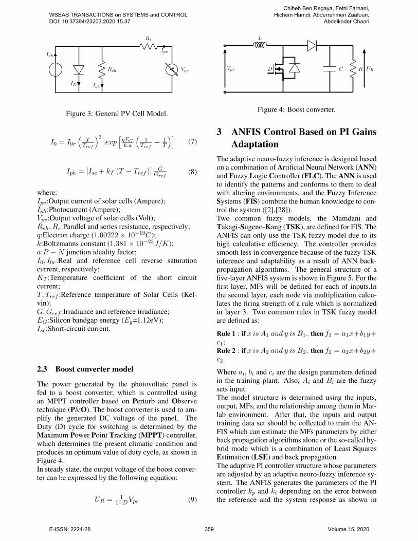
2.3 Boost converter model
The power generated by the photovoltaic panel isfed to a boost converter, which is controlled usingan MPPT controller based on Perturb and Observetechnique (P&O). The boost converter is used to am-plify the generated DC voltage of the panel. TheDuty (D) cycle for switching is determined by theMaximum Power Point Tracking (MPPT) controller,which determines the present climatic condition andproduces an optimum value of duty cycle, as shown inFigure 4.In steady state, the output voltage of the boost conver-ter can be expressed by the following equation:
UR = 11−DVpv (9)
L
C RDVpv UR
Figure 4: Boost converter.
3 ANFIS Control Based on PI GainsAdaptation
The adaptive neuro-fuzzy inference is designed basedon a combination of Artificial Neural Network (ANN)and Fuzzy Logic Controller (FLC). The ANN is usedto identify the patterns and conforms to them to dealwith altering environments, and the Fuzzy InferenceSystems (FIS) combine the human knowledge to con-trol the system ([2],[28]).Two common fuzzy models, the Mamdani andTakagi-Sugeno-Kang (TSK), are defined for FIS. TheANFIS can only use the TSK fuzzy model due to itshigh calculative efficiency. The controller providessmooth less in convergence because of the fuzzy TSKinference and adaptability as a result of ANN back-propagation algorithms. The general structure of afive-layer ANFIS system is shown in Figure 5. For thefirst layer, MFs will be defined for each of inputs.Inthe second layer, each node via multiplication calcu-lates the firing strength of a rule which is normalizedin layer 3. Two common rules in TSK fuzzy modelare defined as:
Rule 1 : if x is A1 and y is B1, then f1 = a1x+b1y+c1;Rule 2 : if x is A2 and y is B2, then f2 = a2x+b2y+c2.
Where ai, bi and ci are the design parameters definedin the training plant. Also, Ai and Bi are the fuzzysets input.The model structure is determined using the inputs,output, MFs, and the relationship among them in Mat-lab environment. After that, the inputs and outputtraining data set should be collected to train the AN-FIS which can estimate the MFs parameters by eitherback propagation algorithms alone or the so-called hy-brid mode which is a combination of Least SquaresEstimation (LSE) and back propagation.The adaptive PI controller structure whose parametersare adjusted by an adaptive neuro-fuzzy inference sy-stem. The ANFIS generates the parameters of the PIcontroller kp and ki depending on the error betweenthe reference and the system response as shown in
WSEAS TRANSACTIONS on SYSTEMS and CONTROL DOI: 10.37394/23203.2020.15.37
Chiheb Ben Regaya, Fethi Farhani, Hichem Hamdi, Abderrahmen Zaafouri,
Abdelkader Chaari
E-ISSN: 2224-28 359 Volume 15, 2020

X
Y
A1
A2
B1
B2
Π
Π
N
N
Π
Π
∑
W1
W2
W1
W2
W1f1
W2f2
fOutput
Layer 1 Layer 2 Layer 3 Layer 4 Layer 5X Y
X Y
Figure 5: Five-layer ANFIS system.
Figure 6 to ensure high performance of the develo-ped control law with compensation of the rotor resis-tance variation effect. The proposed controller usestwo ANFIS: the first generates the kp gain and the se-cond generates ki via another auxiliary parameter β.The adaptive neuro-fuzzy inference system of the PIcontroller is shown in Figure 7.
Ω∗r
ANFIS
Classical PIcontroller
InductionMotor
Ωr
Figure 6: Block diagram of the ANFIS gains adapta-tion of the PI controller.
Ω∗r
kp + kip
ANFIS 1 kβ
k′p1 (.)2ANFIS 2
z−1z
System
×
Ωre
∆e
k′p kp
β
ki
k′i
Figure 7: Block scheme of the proposed speed controlloop using ANFIS.
As indicated in Figure 4, the PI parameters are deter-mined from two adaptive neuro-fuzzy inference sys-tems whose outputs are auxiliary parameters k′p1
, kβ
and inputs are the error between the real and referencespeed (eΩr ), and its derivative (∆eΩr ).The output of the two fuzzy controllers are standardi-zed in intervals between zero and 1. The parameterskp and ki are determined using the following equati-ons:
kp = k′p1k′p (10)
ki =k2p
β(11)
The Neural Network Controller (NNC) is used to es-timate the PI controller gains. The network is trainedfor 1000 epochs and the target error is set to 2.4%.The training error waveform is shown in Figure 8, andthe structure of ANFIS for this controller is presentedin Figure 9. The advantages of the method are its ra-pid tracking speed and high tracking accuracy.
Training Error
Erro
r
Epochs
0.0246
0.0244
0.0242
0.0240
0 200 400 600 800 1000
Figure 8: Training error.
Figure 9: ANFIS model structure.
Figures 10 and 11 represent membership functions forthe two inputs, namely, solar irradiance and PV celltemperature. Figure 12 shows a fuzzy rule for the AN-FIS inputs and output are applied after training.
WSEAS TRANSACTIONS on SYSTEMS and CONTROL DOI: 10.37394/23203.2020.15.37
Chiheb Ben Regaya, Fethi Farhani, Hichem Hamdi, Abderrahmen Zaafouri,
Abdelkader Chaari
E-ISSN: 2224-28 360 Volume 15, 2020

10 20 30 40 50 60 70 80 90 100
0
0.2
0.4
0.6
0.8
1in1mf1 in1mf2 in1mf3
input1
Degreeof
mem
bership
Figure 10: Membership functions for eΩr .
10 20 30 40 50 60 70 80 90 100
0
0.2
0.4
0.6
0.8
1in2mf1 in2mf2 in2mf3
input2
Degreeof
mem
bership
Figure 11: Membership functions for ∆eΩr .
Figure 12: Inputs and Output of ANFIS after Training.
In order to verify the closed-loop stability of the pro-posed controller, the linear time-invariant transfer ma-trix of the closed loop transfer function ANFIS tunedPI speed controller expressed by equation 12 must bestrictly positive real (i.e. All poles of H(s) have ne-gative real parts) for Γl = 0.
H(s) = (sI −A)−1 (12)
where, A the state space matrix of the closed-loopsystem of the ANFIS tuned PI speed controlled in-duction motor. The condition of stability is valida-ted by the root locus study of H(s) using the ’rlocus’command of Matlab. Figures 13 shows clearly that thepoles and zeros of the transfer function H(s) have ne-gative real parts for a speed range between -157 rad/sand 157 rad/s which indicates that the ANFIS tuned PIspeed controlled induction motor under considerationis stable.
−500 −450 −400 −350 −300 −250 −200 −150 −100 −50 0 50 100−200
−150
−100
−50
0
50
100
150
200
Real Axis (s−1)
ImaginaryAxis(s
−1)
Root Locus of the closed loop transfer function H(s)
Figure 13: Poles localization for the transfer matrixH(s) for Ωr = 0↔ ±157 rad/s.
4 Simulation Results and DiscussionThe proposed PI field oriented control of inductionmotor with gains adaptation based on ANFIS has beenverified by simulations. The rotor field oriented cont-rol scheme is illustrated in Figure 14. The simulationresults have been obtained by implementing the con-trol scheme under the Matlab- Simulink environmentwith 50µs sampling period. The motor parameters va-lues of the set-up and the PV panel are given in Tables1 and 2. The reference value of the rotor flux alongthe d-axis has been fixed to 1 Wb.
WSEAS TRANSACTIONS on SYSTEMS and CONTROL DOI: 10.37394/23203.2020.15.37
Chiheb Ben Regaya, Fethi Farhani, Hichem Hamdi, Abderrahmen Zaafouri,
Abdelkader Chaari
E-ISSN: 2224-28 361 Volume 15, 2020

Table 1: Motor parameters values.Symbol Quantity UMRs Stator resistance 2.3 [Ω]
Rr Rotor resistance 1.83 [Ω]
Ls Stator inductance 261 [mH]
Lr Rotor inductance 261 [mH]
M Mutual inductance 245 [mH]
σ Leakage factor 0.134 -J Moment of inertia 0.22 [Kgm2]
f Friction coefficient 0.001 -Vn Rated voltage 380 [V ]
In Rated current 10.4 [A]
Pn Rated power 3 [kW ]
np Number of pole pairs 2 -
Table 2: Parameter values of YHM180-36 M PV pa-nel.
Optimum operation voltage 35.20VOptimum operation current 5.11A
Open-circuit voltage 43VShort-circuit current 5.5A
Maximum power at STC 180WPeak efficiency 16%
Temp. Coefficient of Isc − (0.06± 0.01) %/kTemp. Coefficient of Voc − (78± 10)mV/k
Number of cells 72
4.1 Performances TestsA step reference speed was applied at t=1s and isequal to 157 rad/s. The load torque is applied att=5s. At t=7s, undergone a disturbance on the rotorresistance which has been increased by 50% from itsrated value. The implemented control scheme basedon ANFIS is compared to the classical PI controland adaptive control based on MRAS rotor resistanceobserver using the same speed profile and the sameoperating conditions.Figures 15-17 show the simulations results for theclassical PI without gains adaptation, classical PIcontrol with MRAS rotor resistance observer and theproposed ANFIS control based PI gains adaptation.Figure 15 shows that the rotor speed decrease byalmost 15 rad/s from its rated value, and the rotorspeed error illustrated by figure 16 show that thiserror exceeds 9% when the rotor resistance undergonea variation in case of classical PI without gainsadaptation.Figure 17 shows the effect of sudden change onthe shape of direct and quadratic flux, when a 50%increase of the rotor resistance is introduced, in
case of classical PI control. Just at the moment ofvariation, the orientation of the fluxes is lost, whichdeteriorate the controllers performances.
Inverter
PV panel+
MPPT
IM
3 ∼
Speed sensor
PW
Msignal
generaion
va
vb
vc
dq
abc
ωs
Decouplin
g
P Icontroller
ANFIS gains
adaptation
1M
PIcontroller
PIcontroller
dq
abc
ωs
Ω∗r
Ωrφ∗r
i∗sq
i∗sd
C∗e vsd
vsq
v∗sd
v∗sq
Figure 14: Block diagram of vector control with anadaptive fuzzy logic gains adaptation of the PI speedcontroller.
0 1 2 3 4 5 6 7 8 9 100
20
40
60
80
100
120
140
160
Time [s]
Ω∗ r,
Ωr
[rad/s]
Ω∗r
Ωr (PI)
Ωr (MRAS)
Ωr(PI-ANFIS)
Figure 15: Rotor speed.
Figures 15-17 show also the performance of theadaptive control based ANFIS gains adaptation of thePI speed controller. The obtained result demonstratesthat even if an increase the rotor resistance is introdu-ced at t = 7s, the proposed adaptive control still givesa good orientation of the rotor flux and a good speedtracking, with a speed error which doesn’t exceed0.5% of the rated value. However, the adaptive vectorcontrol based on MRAS rotor resistance observerdoes not guarantee a good tracking of the rotor speedas shown in Figure 15. In this case, when the rotorresistance undergoes a variation, the rotor speeddecrease by almost 5 rad/s from its rated value withthe appearance of ripples as shown in Figures 15-16.Figure 17 shows that using an MRAS rotor resistanceobserver does not guarantee a good fluxes orientation.
WSEAS TRANSACTIONS on SYSTEMS and CONTROL DOI: 10.37394/23203.2020.15.37
Chiheb Ben Regaya, Fethi Farhani, Hichem Hamdi, Abderrahmen Zaafouri,
Abdelkader Chaari
E-ISSN: 2224-28 362 Volume 15, 2020

0 1 2 3 4 5 6 7 8 9 10
0
50
100
150
Temps [s]
Ω∗ r−
Ωr
[rad/s]
eΩr (PI)
eΩr (MRAS)
eΩr (PI-ANFIS)
Figure 16: Rotor speed error.
0 1 2 3 4 5 6 7 8 9 10
0
0.2
0.4
0.6
0.8
1
1.2
Time [s]
φrd,φrq[W
b] φrd (PI)
φrq (PI)
φrd (MRAS)
φrq (MRAS)
φrd (PI-ANFIS)
φrq (PI-ANFIS)
Figure 17: Rotor flux.
4.2 Robustness TestsIn order to test the performance of the propo-sed control scheme which is based on an adaptiveproportional-integral ANFIS controller are again as-sessed by another three tests using the same condi-tion mentioned in the previous subsection 4.1, whichare performed to study the influence of the parame-tric variations for the inertia coefficient, the stator androtor inductances of the induction motor. Simulati-ons results of robustness tests illustrated by Figures18-20 show clearly that the variation of J , Ls and Lrhas practically no effect on the dynamics of speed re-sponse, even in the presence of a rotor resistance vari-ation.The obtained results show clearly that the proposedadaptive control based on ANFIS-PI gains adapta-tion has a powerful approach to allow high perfor-mance control. The obtained simulation results showalso that the PI control with gains adaptation basedon ANFIS can guarantee a high performance cont-rol of induction motor, and prove the efficiency of theproposed control scheme in terms of speed reference
tracking in transients and stand-still operation, rotorflux orientation and load disturbances rejection, evenin the presence of parametric variations.
0 1 2 3 4 5 6 7 8 9 100
20
40
60
80
100
120
140
160
Time [s]
Ω∗ r,
Ωr
[rad/s]
Ω∗r
Ωr for (J/2)
Ωr for (J)
Ωr for (1.5J)
0 1 2 3 4 5 6 7 8 9 100
20
40
60
80
100
120
140
160
Time [s]
Ω∗ r,
Ωr
[rad/s]
Ω∗r
Ωr for (J/2)
Ωr for (J)
Ωr for (1.5J)
Figure 18: Rotor speed (case of J variation).
0 1 2 3 4 5 6 7 8 9 100
20
40
60
80
100
120
140
160
Time [s]
Ω∗ r,
Ωr
[rad/s]
Ω∗r
Ωr for (Ls/2)
Ωr for (Ls)
Ωr for (1.5Ls)
0 1 2 3 4 5 6 7 8 9 100
20
40
60
80
100
120
140
160
Time [s]
Ω∗ r,
Ωr
[rad/s]
Ω∗r
Ωr for (Ls/2)
Ωr for (Ls)
Ωr for (1.5Ls)
Figure 19: Rotor speed (case of Ls variation).
Table 3 shows the quantitative performances in caseof some parametric variations of the proposed adap-tive proportional-integral ANFIS controller. The re-sults illustrate globally that the variation of J , Ls andLr does not deteriorate the performance of the propo-sed control.
WSEAS TRANSACTIONS on SYSTEMS and CONTROL DOI: 10.37394/23203.2020.15.37
Chiheb Ben Regaya, Fethi Farhani, Hichem Hamdi, Abderrahmen Zaafouri,
Abdelkader Chaari
E-ISSN: 2224-28 363 Volume 15, 2020

0 1 2 3 4 5 6 7 8 9 100
20
40
60
80
100
120
140
160
Time [s]
Ω∗ r,
Ωr
[rad/s]
Ω∗r
Ωr for (Lr/2)
Ωr for (Lr)
Ωr for (1.5Lr)
0 1 2 3 4 5 6 7 8 9 100
20
40
60
80
100
120
140
160
Time [s]
Ω∗ r,
Ωr
[rad/s]
Ω∗r
Ωr for (Lr/2)
Ωr for (Lr)
Ωr for (1.5Lr)
Figure 20: Rotor speed (case of Lr variation).
Table 3: Quantitative performances of the proposedcontroller.
Adaptive proportional
Parameter variationsintegral ANFIS controllerSettling time (Tr ± 5%)
Inertia J2 0.34s
coefficient J 0.345s
1.5J 0.35s
Stator Ls
2 0.344s
inductance Ls 0.345s
1.5Ls 0.346s
Rotor Lr
2 0.275s
inductance Lr 0.34s
1.5Lr 0.46s
5 Conclusions
The PI control with gains adaptation based on adap-tive neuro-fuzzy inference system technique is deve-loped in this paper. The proposed method is an alter-native to handle the induction motor rotor resistancevariation problem. This technique uses an adaptivemechanism of the PI gains which is ensured usingan Adaptive Neuro-Fuzzy Inference System (ANFIS)for each gain (kp and ki). The proposed controlscheme can guarantee a high performance comparedto the classical PI control and the adaptive controlusing an MRAS rotor resistance observer. Simula-tion tests confirm the theoretical concepts and showthat this type of adaptive control can overcomes therotor resistance variation. The simulation results sho-wed that the proposed control scheme can guaranteea good performance of the fact that the speed errorexceeds 1% of the rated value.
References:
[1] H. Hamdi, C. Ben Regaya, A. Zaafouri, Real-time study of a photovoltaic system with boostconverter using the PSO-RBF neural network al-gorithms in a MyRio controller, Solar Energy183, 2019, pp. 1-16.
[2] H. Hamdi, C. Ben Regaya, A. Zaafouri, Asliding-neural network control of induction-motor-pump supplied by photovoltaic generator,Prot Control Mod Power Syst 5, 1, 2020, pp. 1-17.
[3] H. Hamdi, C. Ben Regaya, A. Zaafouri, Per-formance improvement of a photovoltaic systemwith a radial basis function network based onparticle swarms optimization, IEEE Internatio-nal Conference on Signal, Control and Commu-nication (SCC), 2019.
[4] R. Saidur, A review on electrical motors energyuse and energy savings, Renewable and Sustai-nable Energy Reviews, 14, 2010, pp. 877-98.
[5] J.T.E Fernando and T. Anbal, Induction mo-tor downsizing as a low-cost strategy to saveenergy, Journal of Cleaner Production, 24, 2012,pp. 117-31.
[6] W. Chakchouk, C. Ben Regaya, A. Zaafouri,A. Sellami, An improved fuzzy logic control ofirrigation station, 4th International Conferenceon Control, Decision and Information Techno-logies (CoDIT), 2017, pp. 259–264.
[7] C. Ben Regaya, W. Chakchouk, A. Zaafouri,A. Sellami, A. Chaari, Adaptive Discrete-timeBackstepping Control of irrigation station, In-ternational Conference on Advanced Systemsand Electric Technologies (IC-ASET), 2017,pp. 158–163.
[8] W. Chakchouk, C. Ben Regaya, A. Zaafouri,A. Sellami, Fuzzy supervisor approach designbased-switching controller for Pumping sta-tion: Experimental validation, MathematicalProblems in Engineering, 2017, pp. 1–12.
[9] F. Mehazzem Fateh and A. Reama, Compara-tive study of integral and classical backsteppingcontrollers in IFOC of induction motor fed byvoltage source inverter, International Journal ofHydrogen Energy, 42(28), 2017, pp. 17953-64.
[10] C. Ben Regaya, F. Farhani, Z. Abderrahmen,C. Abdelkader, A novel adaptive control met-hod for induction motor based on Backsteppingapproach using dSpace DS 1104 control bo-ard, Mechanical Systems and Signal Processing,100, 2018, pp. 466-81.
WSEAS TRANSACTIONS on SYSTEMS and CONTROL DOI: 10.37394/23203.2020.15.37
Chiheb Ben Regaya, Fethi Farhani, Hichem Hamdi, Abderrahmen Zaafouri,
Abdelkader Chaari
E-ISSN: 2224-28 364 Volume 15, 2020

[11] A. Karim, A. Lakrim, D. Tahri, Reduced TimeDomain Behavioral Model of Three-Wire Shiel-ded Power Cables, International Journal of Cir-cuits, Systems and signal processing, 13, 2019,pp. 617-624.
[12] F. Blaschke, The principle of field oriented as ap-plied to the new Tran vector closed-loop controlsystem for rotating machine, Siemens Review,39(4), 1972, pp. 217–20.
[13] I. Takahashi, N. Toshihiko, A New Quick-Response and High-Efficiency Control Strategyof an Induction Motor, IEEE Transactions on In-dustry Applications, 1A-22(5), 1986, pp. 820–27.
[14] L. Amezquita-Brooks, E. Liceaga-Castro,J. Liceaga-Castro, C. Ugalde-Loo, Flux-torquecross-coupling analysis of FOC schemes: Novelperturbation rejection characteristics, ISATransactions 58, 2015, pp. 446–61.
[15] I. Nouira El Badsi, B. El Badsi, A. Masmoudi,Experimental Evaluation of RFOC and DTCStrategies for B6-VSI Fed Induction Motor Dri-ves, 17th international conference on Sciencesand Techniques of Automatic control & compu-ter engineering, STA’, 2016, pp. 488–95.
[16] M. Nait Said, M. Benbouzid, Induction motorsdirect field oriented control with robust on-linetuning of rotor resistance, IEEE Transactionson Energy Conversion, 14(4), 1999, pp. 1038–1042.
[17] A. Bohari, W. Utomo, Z. Haron, N. Zin, S. Sim,R. Ariff, Speed Tracking of Indirect Field Orien-ted Control Induction Motor Using Neural Net-work, Procedia Technology, 11, 2013, pp. 141–46.
[18] L. Taneja, S. Kumar, R Kumar, Current regula-ted induction motor drive with IFOC, In 2014IEEE 6th India International Conference on Po-wer Electronics (IICPE), 2014, pp. 1–5.
[19] C. Ben Regaya, F. Farhani, A. Zaafouri,A. Chaari, Comparison between two methodsfor adjusting the rotor resistance, Internati-onal Review on Modelling and Simulations(I.RE.MO.S), 5(2), 2012, pp. 938–44.
[20] C. Ben Regaya, A. Zaafouri, A. Chaari, Elec-tric drive control with rotor resistance and rotorspeed observers based on fuzzy logic, Mathema-tical Problems in Engineering, 2014, pp. 1–9.
[21] C. Ben Regaya, A. Zaafouri and A. Chaari,A new sliding mode speed observer of electricmotor drive based on fuzzy-logic, Acta Poly-technica Hungarica, 11(3), 2014, pp. 219-232.
[22] C. Ben Regaya, F. Farhani, A. Zaafouri andA. Chaari, High-performance control of imusing mras-fuzzy logic observer, InternationalJournal of Tomography and Simulation, 30(2),2017, pp. 40-51.
[23] M. Gayathri, S. Himavathi and R. Sankaran,Comparison of rotor flux and reactive powerbased mras rotor resistance estimators for vec-tor controlled induction motor drive, Interna-tional Conference on Advances in Engineer-ing, Science and Management (ICAESM), India,2012, pp. 183-189.
[24] A. Zaafouri, C. Ben Regaya, H. Ben Azzaand A. Chaari, Dsp-based adaptive backsteppingusing the tracking errors for high-performancesensorless speed control of induction motordrive, ISA Transactions, 60, 2016, pp. 333-347.
[25] Y. Zahraoui, M. Akherraz, and S. Elbadoui,Improvement of Induction Motor State Obser-vation: Extended Kalman Filter Versus Adap-tive Luenberger Observer, 15, WSEAS TRAN-SACTIONS on SYSTEMS and CONTROL,2020, pp. 120-130.
[26] C. Ben Regaya, Contribution la synthese de loisde commande robuste de la machine inductiontriphase : Validation exprimentale, Ph.D. Thesis,Ecole Suprieure des Sciences et Techniques deTunis, 2016.
[27] S. Motahhir, A. E. Ghzizal, and A. Derouich,Modelisation et commande dun panneau pho-tovoltaque, 2me dition du Congrs Internatinalde Gnie Industriel et Management des Systmes,2015, pp. 118.
[28] H. Souilem, and N. Derbel, Neuro-Fuzzy Cont-rol of Vehicle Active Suspension System, Inter-national Journal of Circuits, Systems and Signalprocessing, 12, 2018, pp. 423431.
Creative Commons Attribution License 4.0 (Attribution 4.0 International, CC BY 4.0)
This article is published under the terms of the Creative Commons Attribution License 4.0 https://creativecommons.org/licenses/by/4.0/deed.en_US
WSEAS TRANSACTIONS on SYSTEMS and CONTROL DOI: 10.37394/23203.2020.15.37
Chiheb Ben Regaya, Fethi Farhani, Hichem Hamdi, Abderrahmen Zaafouri,
Abdelkader Chaari
E-ISSN: 2224-28 365 Volume 15, 2020