robotics and embedded system ppt
25
Robotics and Embedded System By Shashi Verma Rock In Rob
-
Upload
shashi-verma -
Category
Technology
-
view
262 -
download
17
Transcript of robotics and embedded system ppt
Robotics and Embedded System
By
Shashi Verma
Rock In Robos
S. no
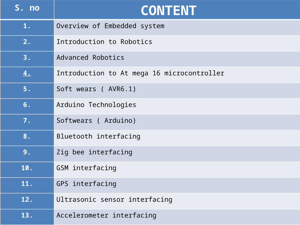
1. Overview of Embedded system
2. Introduction to Robotics
3. Advanced Robotics
4. Introduction to At mega 16 microcontroller
5. Soft wears ( AVR6.1)
6. Arduino Technologies
7. Softwears ( Arduino)
8. Bluetooth interfacing
9. Zig bee interfacing
10. GSM interfacing
11. GPS interfacing
12. Ultrasonic sensor interfacing
13. Accelerometer interfacing
CONTENT
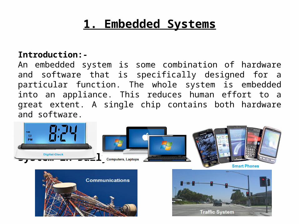
1. Embedded Systems
Introduction:-An embedded system is some combination of hardware and software that is specifically designed for a particular function. The whole system is embedded into an appliance. This reduces human effort to a great extent. A single chip contains both hardware and software. Embedded System in Daily Life
2. Introduction to Robotics
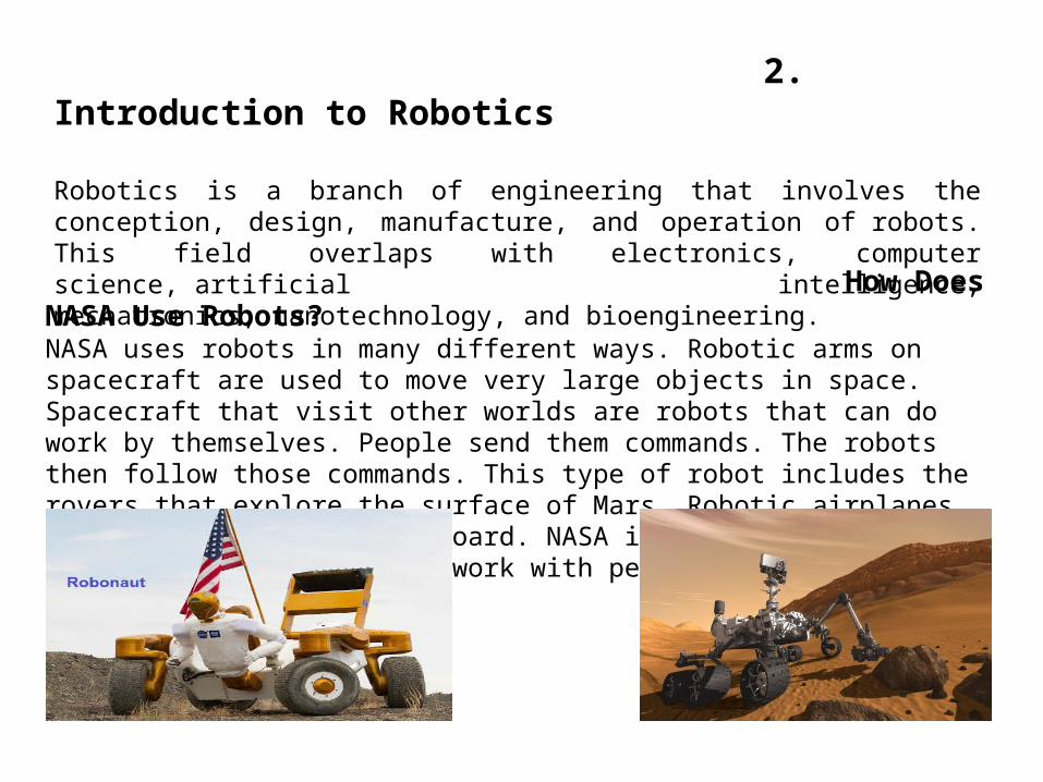
Robotics is a branch of engineering that involves the conception, design, manufacture, and operation of robots. This field overlaps with electronics, computer science, artificial intelligence, mechatronics, nanotechnology, and bioengineering.
How Does NASA Use Robots? NASA uses robots in many different ways. Robotic arms on spacecraft are used to move very large objects in space. Spacecraft that visit other worlds are robots that can do work by themselves. People send them commands. The robots then follow those commands. This type of robot includes the rovers that explore the surface of Mars. Robotic airplanes can fly without a pilot aboard. NASA is researching new types of robots that will work with people and help them.
3. Advanced Robotics
Advanced Robotics basically deals with interfacing advance module such as DTMF (Dual tone multiple frequency), Bluetooth, Zigbee, interfacing of GSM module, interfacing of GPS module, interfacing of ultra sonic sensor and interfacing of accelerometer.Each module is different from another in the respect where ultrasonic sensor is used to find the distance between two large objects whereas a Bluetooth module is used to communicate wirelessly. GPS module is used to find the location of an object whereas GSM module is used to send the message or to make a call.
4. INTRODUCTION TO ATMEGA MICROCONTROLLER
A Microcontroller is a programmable digital processor with necessary peripherals. Both microcontrollers and microprocessors are complex sequential digital circuits meant to carry out job according to the program / instructions. ATMEGA16 MICROCONTROLLER: ATmega16 is an 8-bit high performance microcontroller of Atmel’s Mega AVR family with low power consumption. Atmega16 is based on enhanced RISC (Reduced Instruction Set Computing, Know more about RISC and CISC Architecture)
Some of the features of Atmega16 are:16KB of Flash memory1KB of SRAM512 Bytes of EEPROMAvailable in 40-Pin DIP8- Channel 10-bit ADCTwo 8-bit Timers/CountersOne 16-bit Timer/Counter4 PWM ChannelsSerial USARTDigital to Analog Comparator
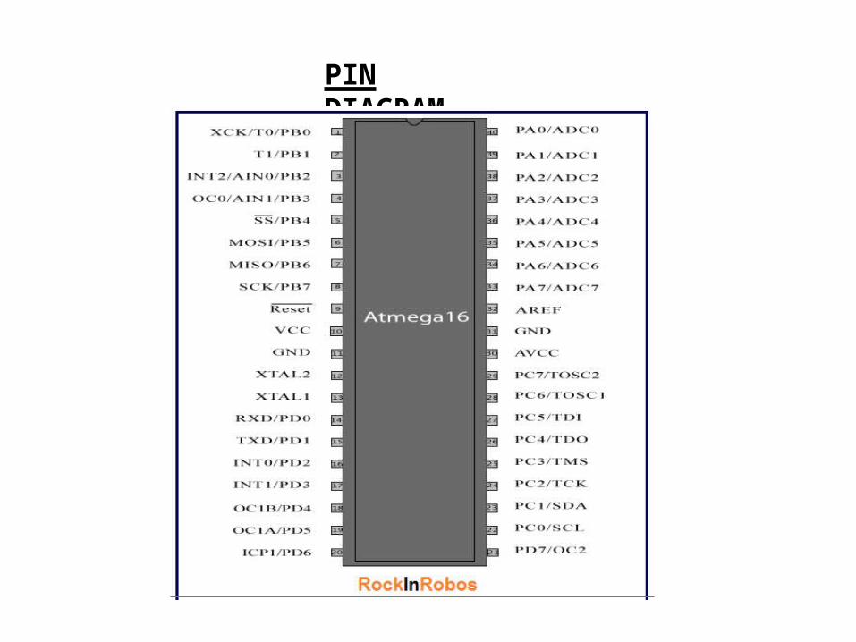
PIN DIAGRAM

Softwears
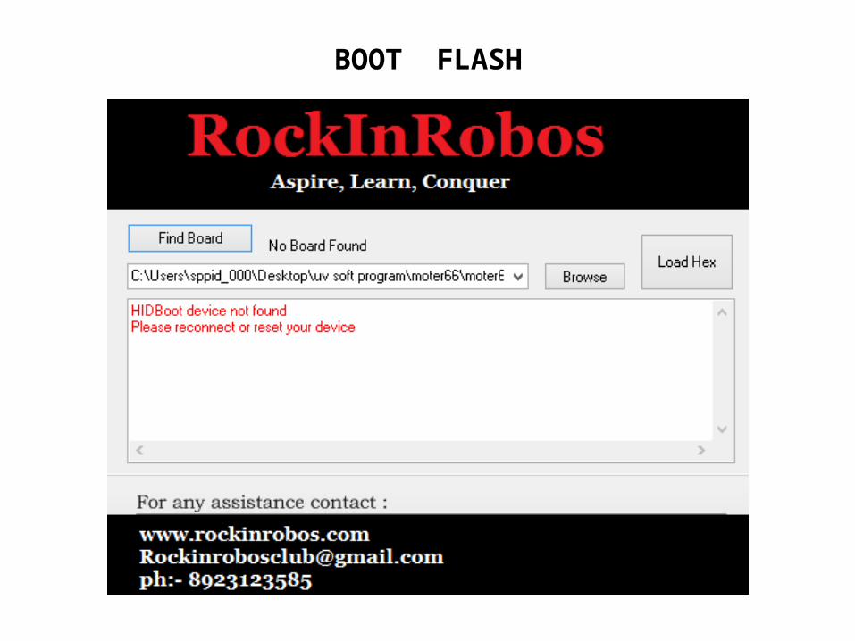
BOOT FLASH
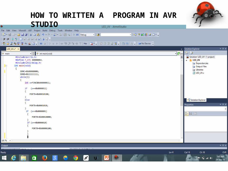
HOW TO WRITTEN A PROGRAM IN AVR STUDIO
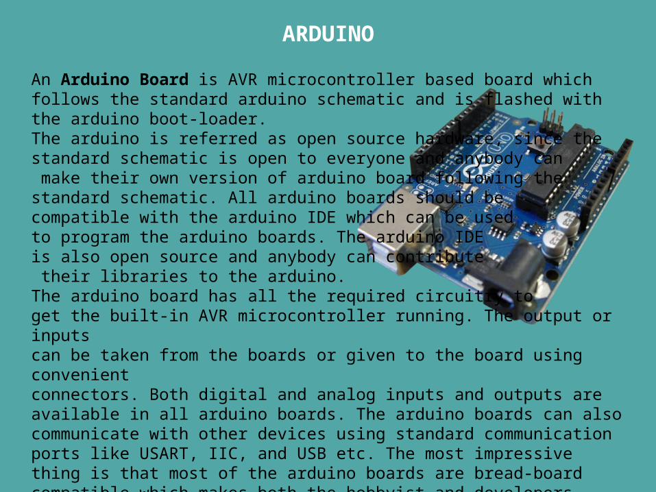
ARDUINO
An Arduino Board is AVR microcontroller based board which follows the standard arduino schematic and is flashed with the arduino boot-loader. The arduino is referred as open source hardware, since the standard schematic is open to everyone and anybody can make their own version of arduino board following the standard schematic. All arduino boards should be compatible with the arduino IDE which can be used to program the arduino boards. The arduino IDE is also open source and anybody can contribute their libraries to the arduino.The arduino board has all the required circuitry to get the built-in AVR microcontroller running. The output or inputs can be taken from the boards or given to the board using convenient connectors. Both digital and analog inputs and outputs are available in all arduino boards. The arduino boards can also communicate with other devices using standard communication ports like USART, IIC, and USB etc. The most impressive thing is that most of the arduino boards are bread-board compatible which makes both the hobbyist and developers happy.
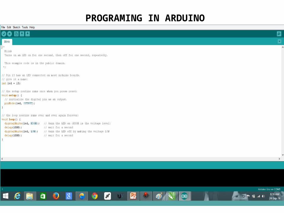
PROGRAMING IN ARDUINO
Bluetooth is a wireless technology standard for exchanging data over short distances (using short-wavelength UHF radio waves in the ISM band from 2.4 to 2.485 GHz from fixed and mobile devices, and building personal area networks (PANs). Invented by telecom vendor Ericsson in 1994, it was originally conceived as a wireless alternative to RS-232 data cables. It can connect several devices, overcoming problems of synchronization.
Organization of Bluetooth
In May of 1998, Intel, Ericsson, Nokia, IBM and Toshiba were formed as a Special Interest Group, named SIG; its goal is to set up a short range radio frequency wireless technology. By June of 1999, members of SIG had been increased to 751 members, which includes Compaq、Dell 、 Motorola 、 3Com 、 HP 、 Lucent 、 and Samsung, and they have all come to a consensus of royalty free standard in order to lower the technical cost for making it being widely used.
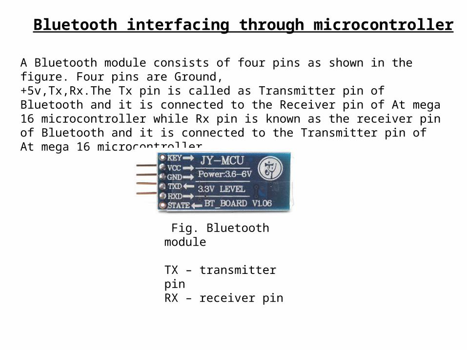
Bluetooth interfacing through microcontroller
A Bluetooth module consists of four pins as shown in the figure. Four pins are Ground,+5v,Tx,Rx.The Tx pin is called as Transmitter pin of Bluetooth and it is connected to the Receiver pin of At mega 16 microcontroller while Rx pin is known as the receiver pin of Bluetooth and it is connected to the Transmitter pin of At mega 16 microcontroller.
Fig. Bluetooth module
TX – transmitter pinRX – receiver pin
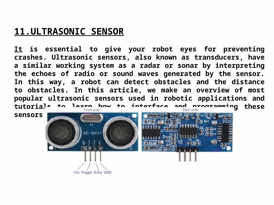
11.ULTRASONIC SENSOR It is essential to give your robot eyes for preventing crashes. Ultrasonic sensors, also known as transducers, have a similar working system as a radar or sonar by interpreting the echoes of radio or sound waves generated by the sensor. In this way, a robot can detect obstacles and the distance to obstacles. In this article, we make an overview of most popular ultrasonic sensors used in robotic applications and tutorials to learn how to interface and programming these sensors in order to build robots.
HC-SR04 provides measurement function between 2 and 400 centimetres at range accuracy of 3 millimetres. The HC-SR04 module hosts the ultrasonic transmitter, the receiver and control circuit.The HR-SR04 has four pins namely Vcc, Trigger, Echo, GND and they are explained in detail below. 1) VCC: 5V DC supply voltage is connected to this pin. 2) Trigger: The trigger signal for starting the transmission is given to this pin. The trigger signal must be a pulse with 10uS high time. When the module receives a valid trigger signal it issues 8 pulses of 40 KHz ultrasonic sound from the transmitter. The echo of this sound is picked by the receiver. 3) Echo: At this pin, the module outputs a waveform with high time proportional to the distance. 4) GND: Ground is connected to this pin.
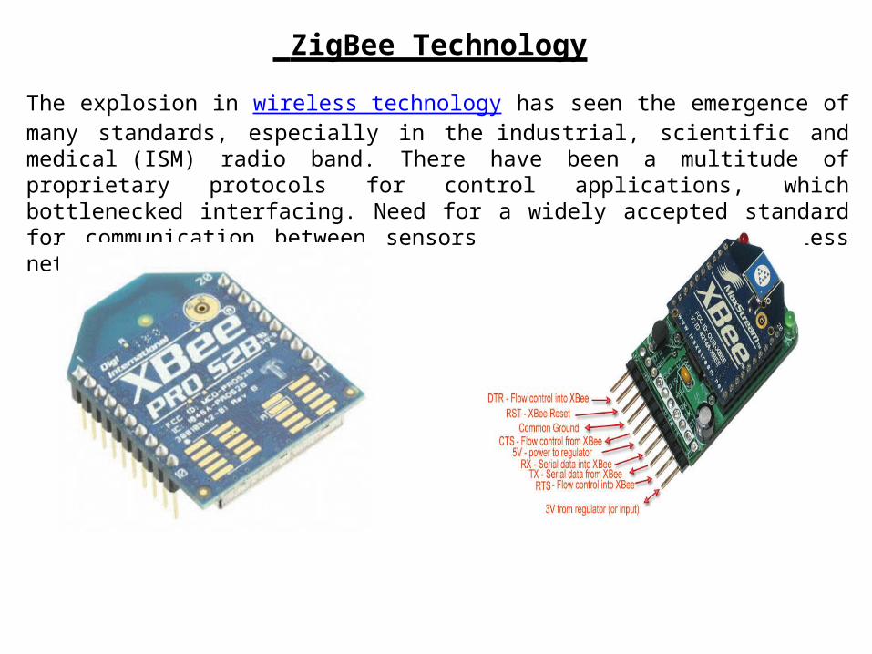
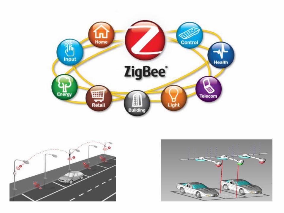
ZigBee Technology
The explosion in wireless technology has seen the emergence of many standards, especially in the industrial, scientific and medical (ISM) radio band. There have been a multitude of proprietary protocols for control applications, which bottlenecked interfacing. Need for a widely accepted standard for communication between sensors in low data rate wireless networks was felt.
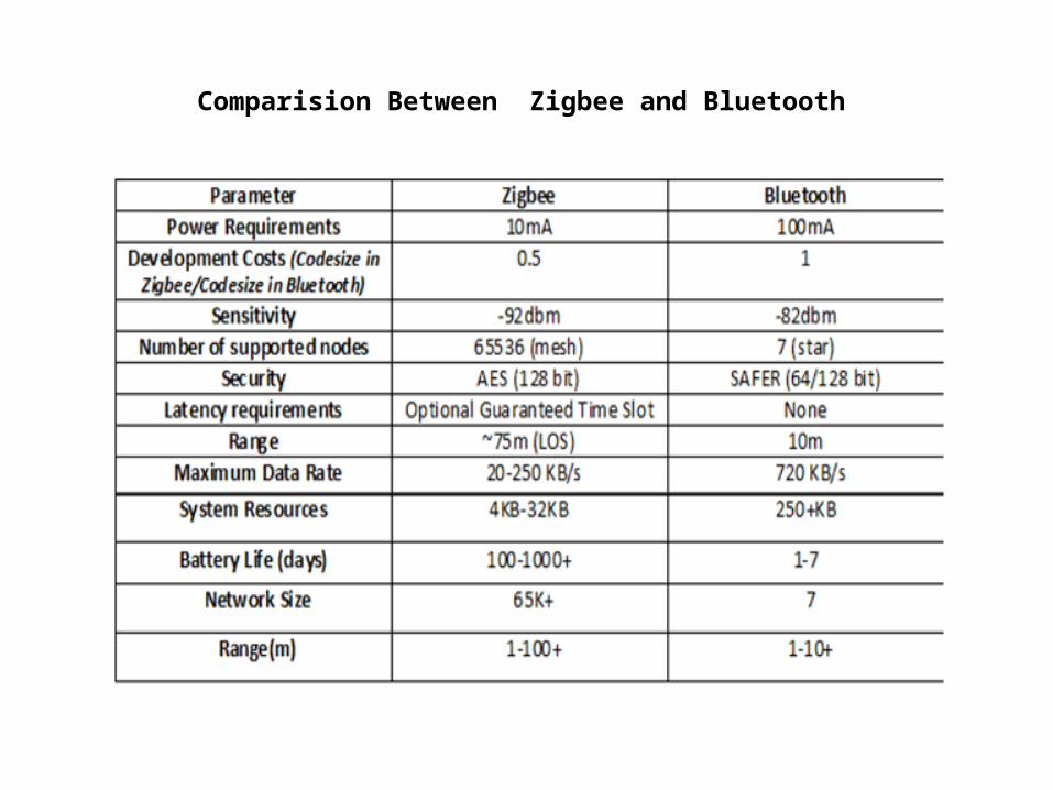
Comparision Between Zigbee and Bluetooth
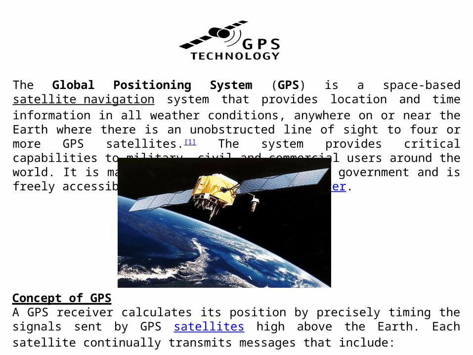
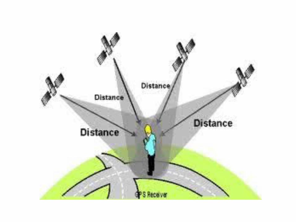
The Global Positioning System (GPS) is a space-based satellite navigation system that provides location and time information in all weather conditions, anywhere on or near the Earth where there is an unobstructed line of sight to four or more GPS satellites.[1] The system provides critical capabilities to military, civil and commercial users around the world. It is maintained by the United States government and is freely accessible to anyone with a GPS receiver.
Concept of GPSA GPS receiver calculates its position by precisely timing the signals sent by GPS satellites high above the Earth. Each satellite continually transmits messages that include:
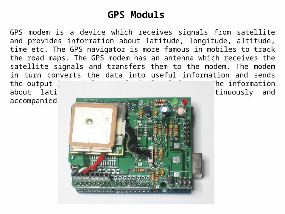
GPS Moduls
GPS modem is a device which receives signals from satellite and provides information about latitude, longitude, altitude, time etc. The GPS navigator is more famous in mobiles to track the road maps. The GPS modem has an antenna which receives the satellite signals and transfers them to the modem. The modem in turn converts the data into useful information and sends the output in serial RS232 logic level format. The information about latitude, longitude etc is sent continuously and accompanied by an identifier string.
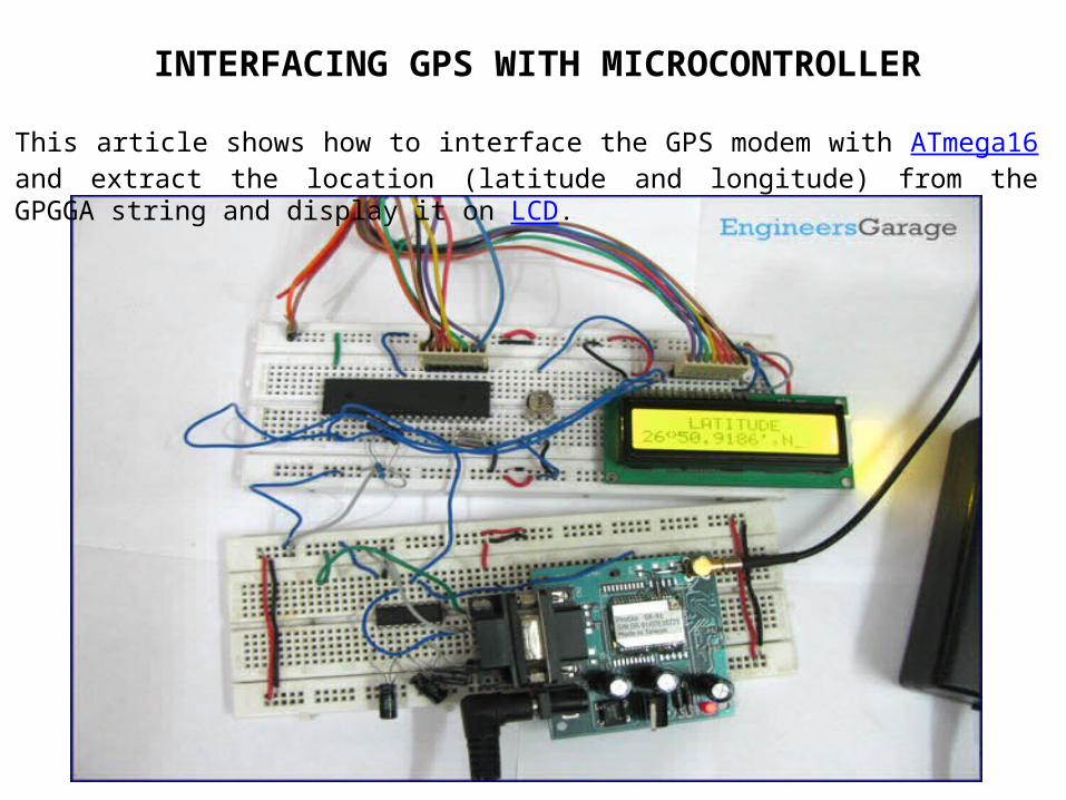
This article shows how to interface the GPS modem with ATmega16 and extract the location (latitude and longitude) from the GPGGA string and display it on LCD.
INTERFACING GPS WITH MICROCONTROLLER
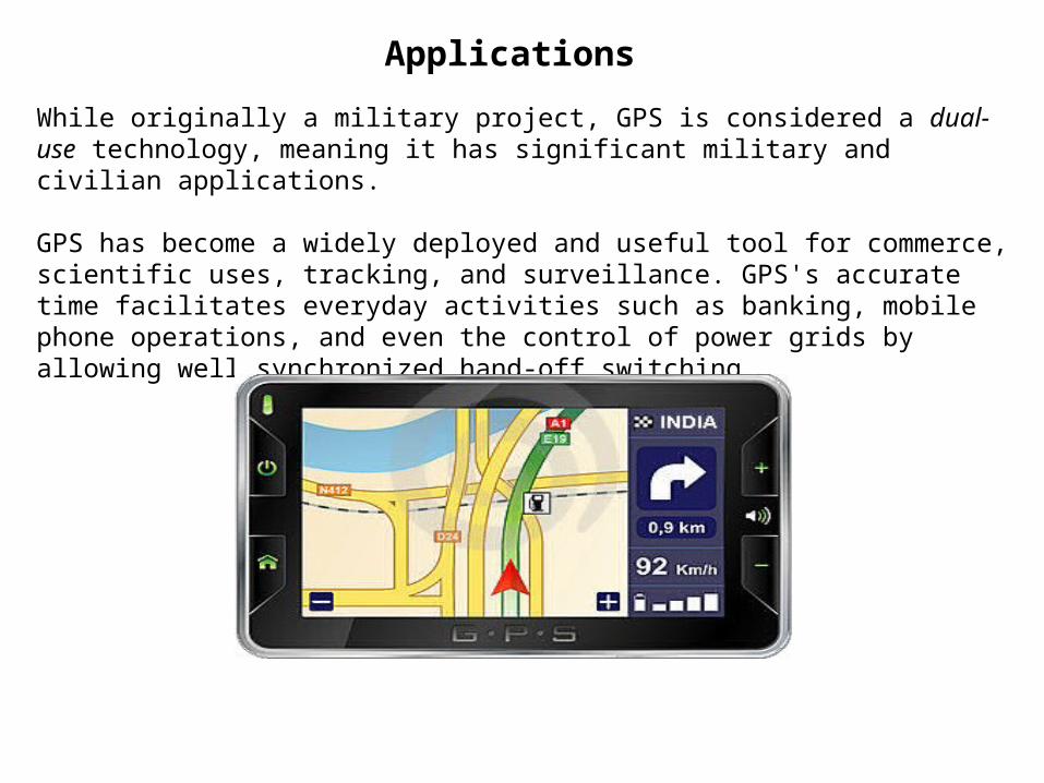
Applications
While originally a military project, GPS is considered a dual-use technology, meaning it has significant military and civilian applications.
GPS has become a widely deployed and useful tool for commerce, scientific uses, tracking, and surveillance. GPS's accurate time facilitates everyday activities such as banking, mobile phone operations, and even the control of power grids by allowing well synchronized hand-off switching.