Robotically Actuated Prevention/Intervention Device Full of Innovative and Responsible Engineering...
47
Robotically Actuated Prevention/Intervention Device Full of Innovative and Responsible Engineering Critical Design Review February 25, 2010 Riley Pack Eric Pahlke Kelly Shuster Greg Stahl RAPID FIRE
-
date post
21-Dec-2015 -
Category
Documents
-
view
217 -
download
0
Transcript of Robotically Actuated Prevention/Intervention Device Full of Innovative and Responsible Engineering...

Robotically Actuated Prevention/Intervention Device Full of Innovative and Responsible Engineering
Critical Design ReviewFebruary 25, 2010
Riley PackEric Pahlke
Kelly ShusterGreg Stahl
RAPID FIRE

PROJECT OVERVIEW• The RAPID FIRE system will be able to recognize moving
targets in a room, choose the optimal target, and track it.
• Recognize one or more moving targets using digital cameras.
• Choose the optimal target, track its movement, and fire a projectile (foam dart or disk) at it.
• Be capable of fully autonomous operation.
• Have a user interface that allows for control of modes, manual turret control, and image viewing.
• Operate off of AC wall power.
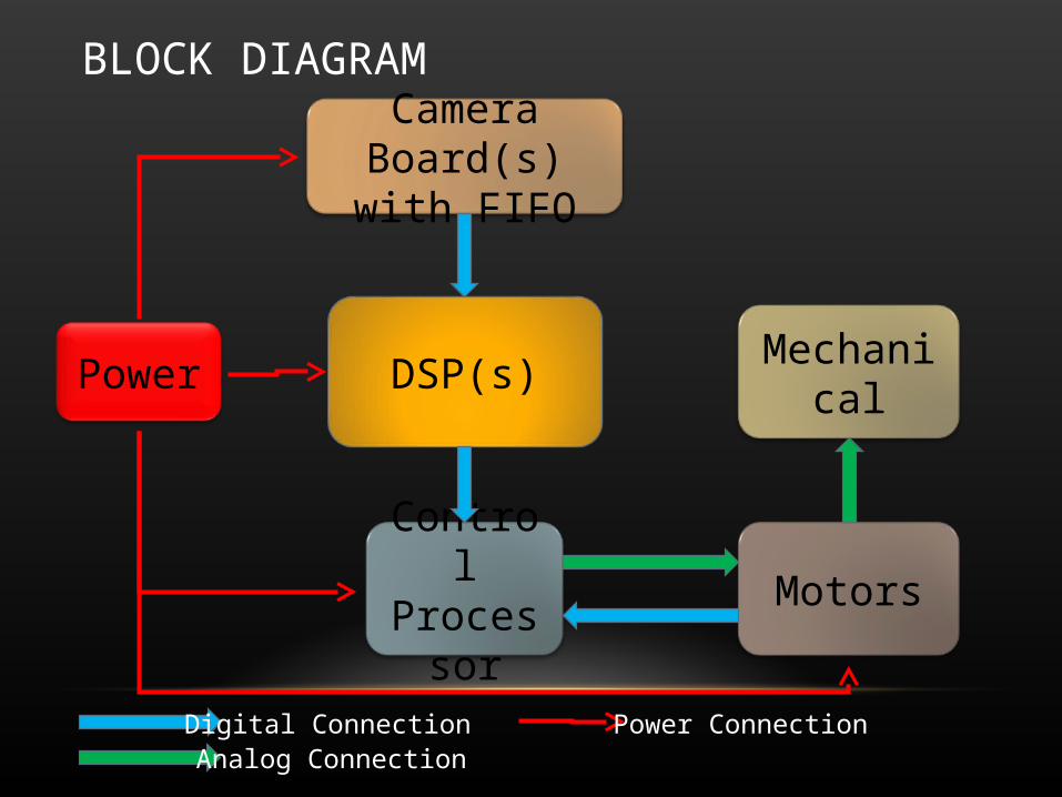
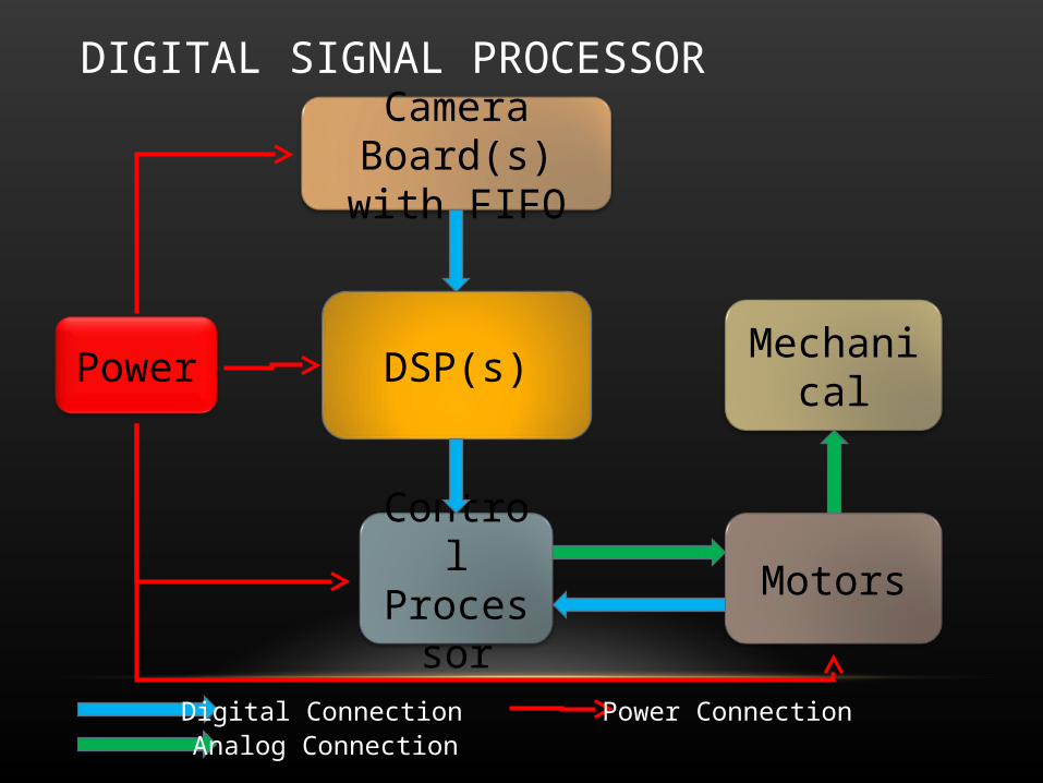
BLOCK DIAGRAM
Power DSP(s)
Control Processor Motors
Camera Board(s) with FIFO
Digital ConnectionAnalog Connection
Power Connection
Mechanical
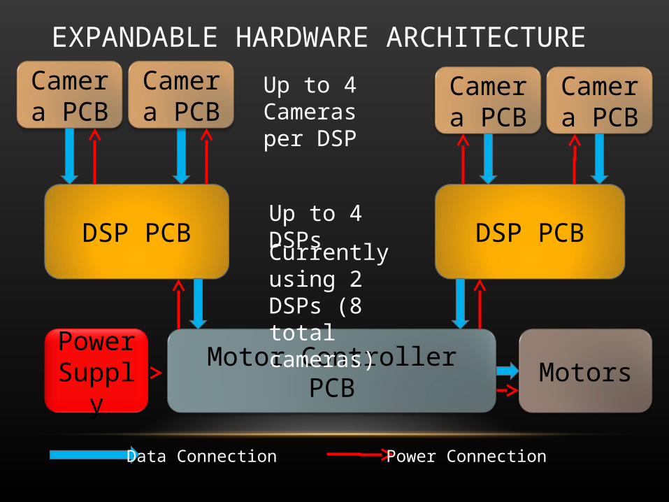
EXPANDABLE HARDWARE ARCHITECTURE
Power Supply
DSP PCB
Motor Controller PCB
Camera PCB
Data Connection Power Connection
Camera PCB
Camera PCB
Camera PCB
DSP PCB
Motors
Up to 4 Cameras per DSP
Up to 4 DSPs
Currently using 2 DSPs (8 total cameras)

CONTROL PROCESSOR
Power DSP(s)
Control Processor Motors
Camera Board(s) with FIFO
Digital ConnectionAnalog Connection
Power Connection
Mechanical
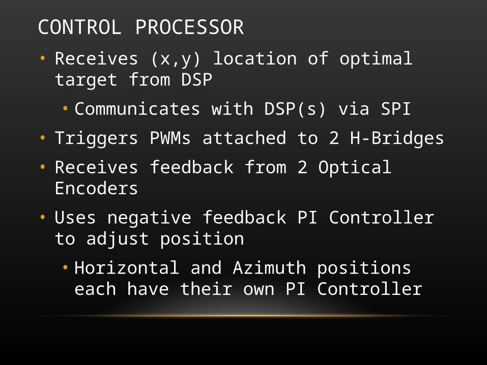
CONTROL PROCESSOR
• Receives (x,y) location of optimal target from DSP
• Communicates with DSP(s) via SPI
• Triggers PWMs attached to 2 H-Bridges
• Receives feedback from 2 Optical Encoders
• Uses negative feedback PI Controller to adjust position
• Horizontal and Azimuth positions each have their own PI Controller
CONTROL PROCESSOR
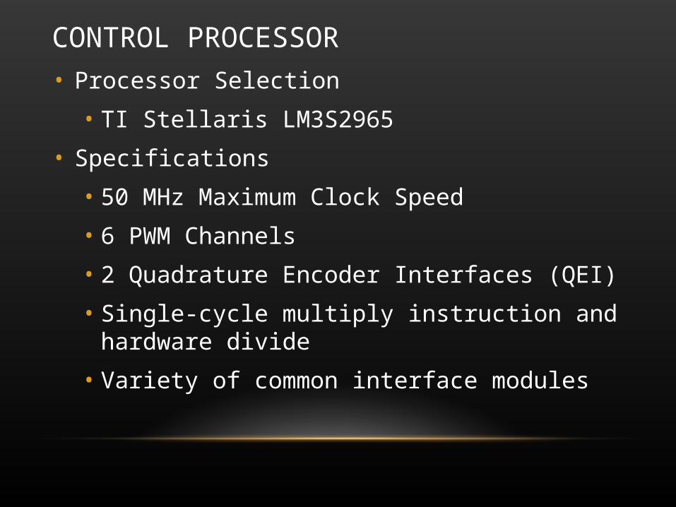
• Processor Selection
• TI Stellaris LM3S2965
• Specifications
• 50 MHz Maximum Clock Speed
• 6 PWM Channels
• 2 Quadrature Encoder Interfaces (QEI)
• Single-cycle multiply instruction and hardware divide
• Variety of common interface modules
CONTROL PROCESSOR
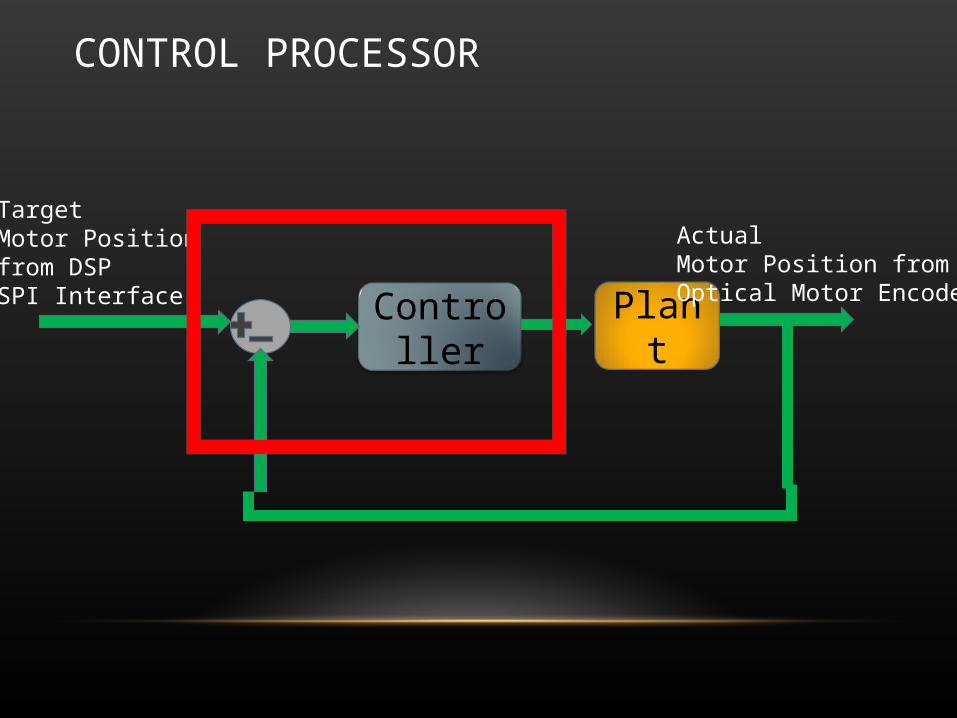
PlantController
Target Motor Position from DSP SPI Interface
Actual Motor Position fromOptical Motor Encoder

CONTROL PROCESSOR
KPs + KI
Target Position
Actual Position
J = 0.5*M*R2
T = 0.4689 Nm = 66.4 oz-in = 80% of Max Efficiency
b = 0.045 M = 2.3kg R = 4.5 in
CONTROL PROCESSOR
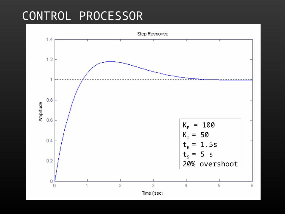
KP = 100KI = 50tR = 1.5stS = 5 s20% overshoot

CONTROL PROCESSOR

CAMERA(S)
Power DSP(s)
Control Processor Motors
Camera Board(s) with FIFO
Digital ConnectionAnalog Connection
Power Connection
Mechanical

CAMERA(S)• Camera Selection
• Toshiba TCM8230MD from Sparkfun
• Specifications
• 15 or 30 FPS
• VGA or QVGA supported
• Digital Output (YUV422 or RGB 565)
• Auto Gain Control, Auto White Balance
http://www.sparkfun.com/commerce/product_info.php?products_id=8667
CAMERA(S)
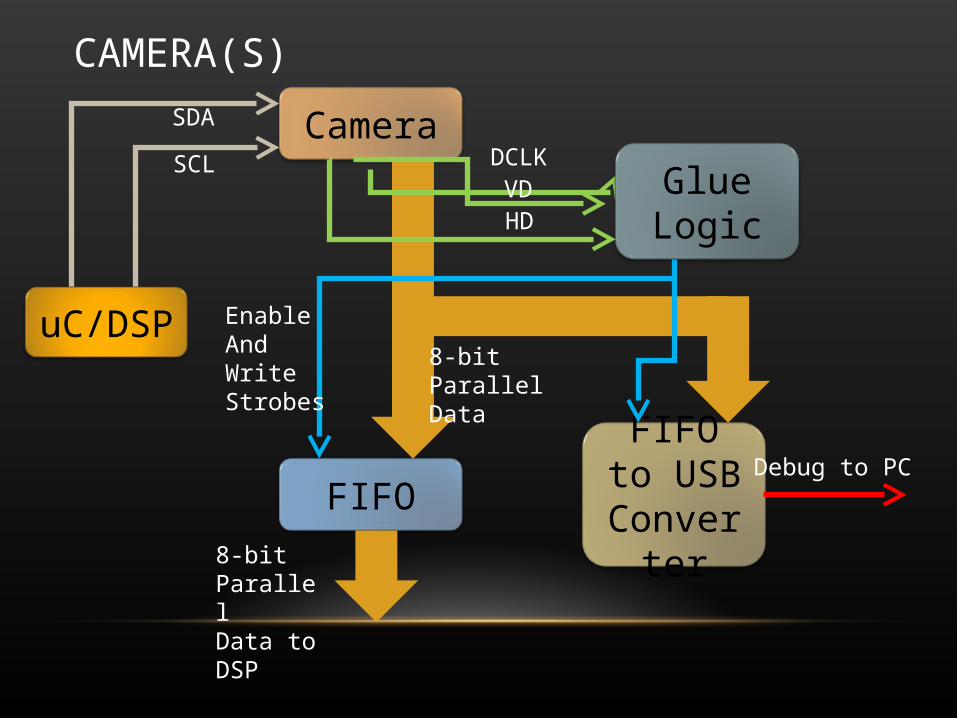
Camera
FIFOFIFO to
USB Converter
8-bit Parallel Data
Glue LogicDCLK
VDHD
EnableAndWriteStrobes
Debug to PC
SDA
SCL
uC/DSP
8-bit Parallel Data to DSP

CAMERA(S) – TEST BOARD
CameraUSB-FIFO
FIFO
SPLD

CAMERA(S) – TEST BOARD
• Almost Able to Take Sub-QCIF (128 x 96) Resolution Pictures
• USB Write Speed Too Slow
• Solution: Upgrade to Faster USB Chip
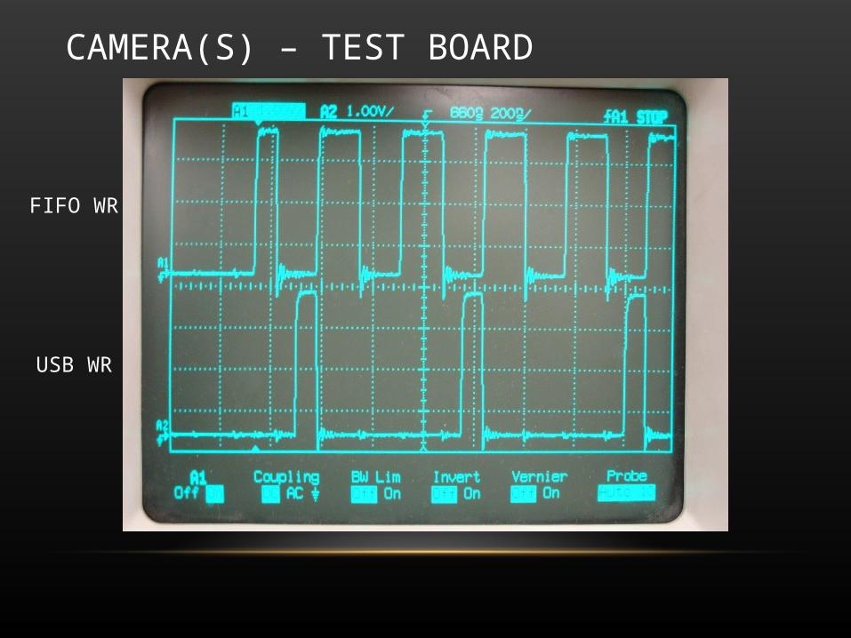
CAMERA(S) – TEST BOARD
FIFO WR
USB WR
CAMERA(S) – REVISION 2
• Current Camera Status
• Ready to Order Camera Board Revision 2
• Updated USB-FIFO Chip to Allow for 8 MBytes/sec
• Changed to Asynchronous FIFO to Simplify DSP Interface
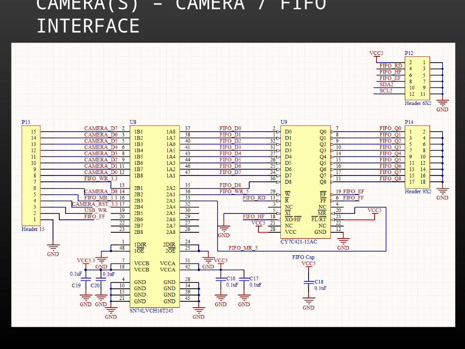
CAMERA(S) – CAMERA / FIFO INTERFACE
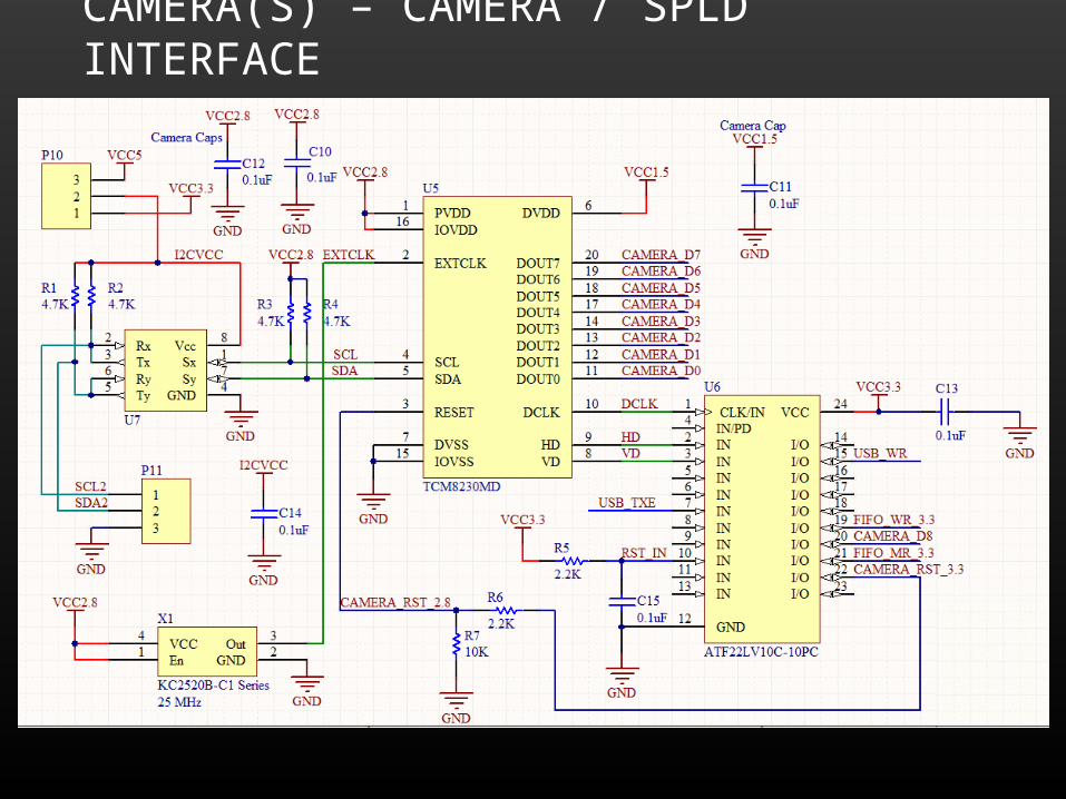
CAMERA(S) – CAMERA / SPLD INTERFACE
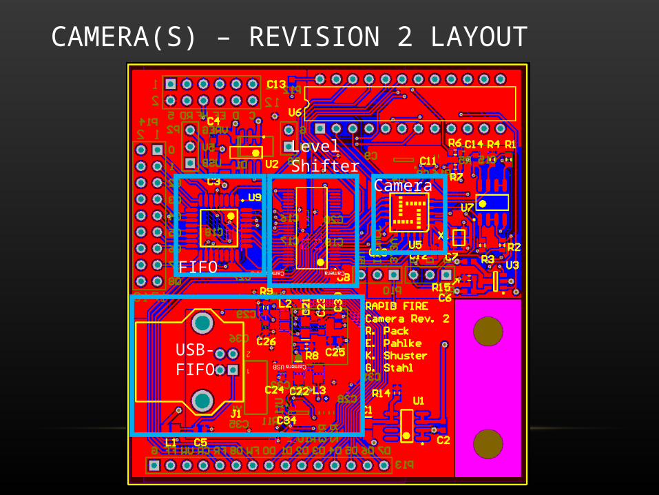
CAMERA(S) – REVISION 2 LAYOUT
Camera
LevelShifter
FIFO
USB-FIFO
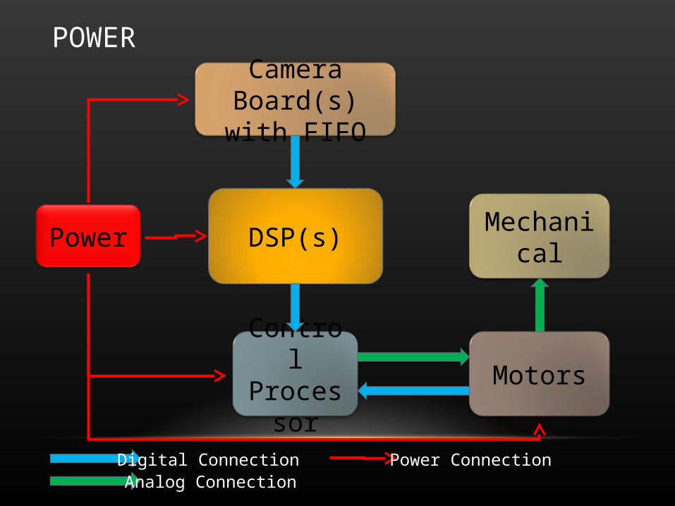
POWER
Power DSP(s)
Control Processor Motors
Camera Board(s) with FIFO
Digital ConnectionAnalog Connection
Power Connection
Mechanical
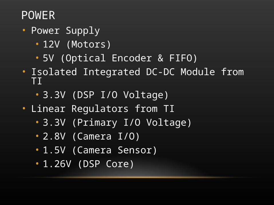
POWER• Power Supply
• 12V (Motors)• 5V (Optical Encoder & FIFO)
• Isolated Integrated DC-DC Module from TI• 3.3V (DSP I/O Voltage)
• Linear Regulators from TI• 3.3V (Primary I/O Voltage)• 2.8V (Camera I/O)• 1.5V (Camera Sensor)• 1.26V (DSP Core)
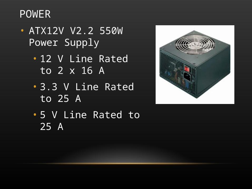
POWER
• ATX12V V2.2 550W Power Supply
• 12 V Line Rated to 2 x 16 A
• 3.3 V Line Rated to 25 A
• 5 V Line Rated to 25 A
DIGITAL SIGNAL PROCESSOR
Power DSP(s)
Control Processor Motors
Camera Board(s) with FIFO
Digital ConnectionAnalog Connection
Power Connection
Mechanical
DIGITAL SIGNAL PROCESSOR• Processes images from CMOS cameras to detect and
track moving targets• Subtraction for motion detection• Blob detection algorithm
• Replaced open source library with custom algorithm to make integration to DSP easier
• Communicates with the motor control processor• Sends debug data to PC using FIFO to USB
• USB is an easier debug port than an LCD
DIGITAL SIGNAL PROCESSOR• DSP Selection
• TI TMS320VC5501• Slightly lower performance than original selection, but QFP package greatly
reduces cost and risk. • Specifications
• 300 MHz, up to 600 MIPS• Hardware Memory Interface
• Used for SDRAM, FIFOs, FIFO to USB• Hardware I2C and SPI Controllers
• I2C used to control cameras and I/O expanders, and for boot loader• SPI used to transfer data to the motor controller
• Driver Library Available from TI

DIGITAL SIGNAL PROCESSOR PCB• Four layer board
• DSP• SDRAM• Hardware support for 4 cameras
• IO and I2C expanders allow multiple cameras to send data through the DSP’s External Memory Interface
• FIFO to USB converter (same as on camera boards) allows the DSP to send images and computation results to a PC
• Status: Schematic and Layout 100%, almost ready to order
DIGITAL SIGNAL PROCESSOR PCB
• Boot loader
• DSP has an I2C EEPROM boot mode
• Use an ATMEGA32 AVR to transfer code from RS-232 to I2C EEPROMs
• Isolation
• All signals from the DSP connecting off the board are isolated to protect the DSP (ISO7240 from TI)
• The 3.3V DC-DC converter for the DSP is isolated (DCR010503 from TI)
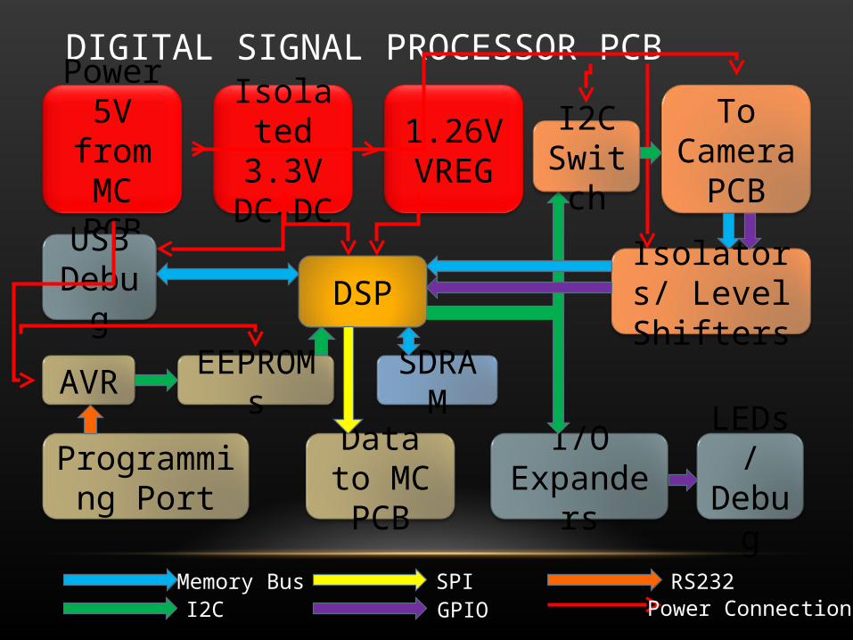
DIGITAL SIGNAL PROCESSOR PCB
Power5V from MC PCB
DSPUSB
Debug
I/O Expanders
To Camera
PCB
Memory BusI2C Power Connection
Isolators/ Level Shifters
Isolated 3.3V
DC-DC
1.26V VREG
I2C Switch
LEDs/ Debug
SDRAMAVR
Programming Port
EEPROMs
GPIOSPI
Data to MC PCB
RS232

DIGITAL SIGNAL PROCESSOR PCB LAYOUT
0 0
00
5
6
7
8
4
3
2
1
3
2
1
211 2
3
2
1
01
2
1
2
1
2
1
10
11
12
17
18
9
8
7
2
1
10
11
12
17
18
9
8
7
2
1
10
11
12
17
18
9
8
7
2
1
2
2
1
1
1
2
2
1
2
1
2
1
2
1
1
2
28 29 30 31 32 33 34 35 36 37 38 39 40 41 42 43 44 45 46 47 48 49 50 51 52 53 54
27 26 25 24 23 22 21 20 19 18 17 16 15 14 13 12 11 10 9 8 7 6 5 4 3 2 1
2
1
1
2
1
2
1 2
2 1
2
1
2 1
2 1
21
21
21
21
8 7 6 5 4 3 2 1
12
12
1 212
1 2
1 2 1 2
12
1
2
2
1
2
11
2
1
2
121 2
1
2
12
1
2
1 2
1 2
1 2
12
1 2
1 2
1
2
1
2
12
2 1
2
1
2
1
2
1
2 1
2
1
2 1
2 1
2 1
2 1
2 1
2 1
2 1
2 121
21
21
21
21
21
21
21
21
21
21
21
21
21
21
21
1 2
1 2
3 4
5 6
11
10
1
6
2
7
3
8
4
9
5
11
10
1
6
2
7
3
8
4
9
5
1
2
1
2
1
18
17
16
15
14
13
12
11
10
9
8
7
6
5
4
3
2
1
18
17
16
15
14
13
12
11
10
9
8
7
6
5
4
3
2
1
2
3
4
5
6
7
81
2
3
4
5
6
7
8
1
2
3
4
5
6
7
8
12
11
10
9
8
7
6
5
4
3
2
1
12
11
10
9
8
7
6
5
4
3
2
1
12
11
10
9
8
7
6
5
4
3
2
1
12
11
10
9
8
7
6
5
4
3
2
1
1
2
3
4
5
6
7
8
9
10
11
12
13
14
15
16
5 13 15 17 2119 2927 3125 3323 35 37
3836343230282624222018161412108642
1 1193 7
1
32
1212 12
1
2
1
2
1 2
12
1
2
12
1
2
12
12
12
12
1
2
12
2
1
1
2 1
2
1 2 3
45
6
1
2
3
4
5
1
2
3 4
5
6
9 10 11 12 13 14 15 16
8 7 6 5 4 3 2 1
9 10 11 12 13 14 15 16
8 7 6 5 4 3 2 1
910111213141516
87654321
1
2
34
5
910111213141516
87654321
12345678
161514131211109
1234567891011
12
13
14
15
16
17
18
19
20
21
22
23 24 25 26 27 28 29 30 31 32 33
34
35
36
37
38
39
40
41
42
43
44
1
2
3
4
8
7
6
5
1
2
3
4
8
7
6
5
12345678910
20191817161514131211
1
2
3
4
8
7
6
5
1
2
3
4
8
7
6
5
910111213141516
87654321
2
1
1
2
1
2
1234
8765
6
5
4
32
1
1
2
1
2
7 6 5 4 2 13
12
5
4
3
2
1
1 2
21
1
1
2
2
1
0
4 3 2 1
9 10 11 12 13 14 15 16
8 7 6 5 4 3 2 1
1
2
3
1 2
1 2
U_DSP General
U_DSP Host Port
U_DSP Memory Control
U_DSP USB
U_Interface to Camera
U_Interface to Motor Control
U_IO Expanders
U_Programming and Debug
U_DSP Power
Cam0
Cam1
Cam2
Cam3
DSP
Boot loader
SDRAM
ISOLATORS
I/O ExpandersTo Cameras
To MCUSB
RS232
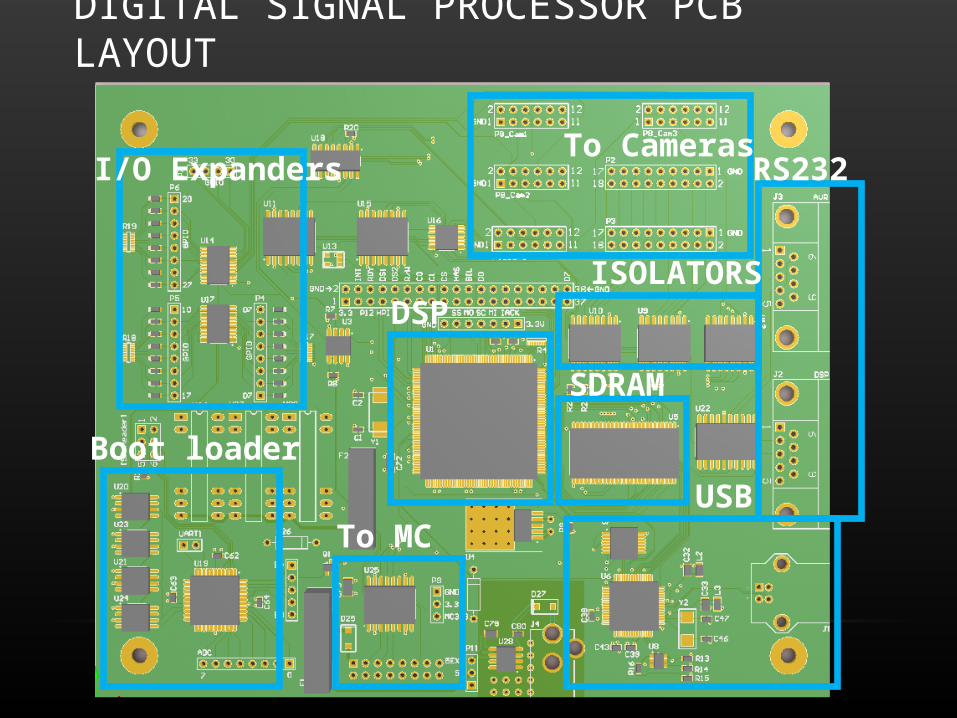
DIGITAL SIGNAL PROCESSOR PCB LAYOUT
DSP
Boot loader
SDRAM
ISOLATORS
I/O ExpandersTo Cameras
To MCUSB
RS232
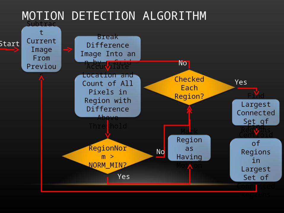
MOTION DETECTION ALGORITHMSubtract Current Image From
Previous
Break Difference Image Into an n-by-n
Grid
Accumulate Location and Count of All
Pixels in Region with Difference Above
Threshold
RegionNorm > NORM_MIN?
Mark Region as Having
Motion
Checked Each Region?
No
Yes
No
Yes
Find Largest Connected Set
of Regions
Find Centroid of Regions in
Largest Set of Connected
Regions
Start

MOTORS/MECHANICAL
Power DSP(s)
Control Processor Motors
Camera Board(s) with FIFO
Digital ConnectionAnalog Connection
Power Connection
Mechanical
MOTORS/MECHANICAL
• Two rotating platforms have been created
• One platform for azimuth, one for elevation
• Rotation achieved using turntables (Lazy Susan)
• DC motors used to rotate platforms
• Controlled with H-Bridge with PWM control
• Protection for deactivation feedback voltage from motor inductance
• Digital optical encoder used for position detection
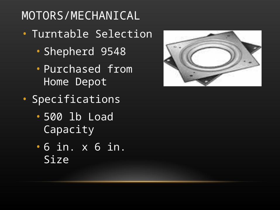
MOTORS/MECHANICAL
• Turntable Selection
• Shepherd 9548
• Purchased from Home Depot
• Specifications
• 500 lb Load Capacity
• 6 in. x 6 in. Size
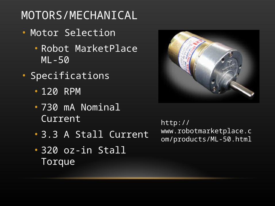
MOTORS/MECHANICAL
• Motor Selection
• Robot MarketPlace ML-50
• Specifications
• 120 RPM
• 730 mA Nominal Current
• 3.3 A Stall Current
• 320 oz-in Stall Torque
http://www.robotmarketplace.com/products/ML-50.html
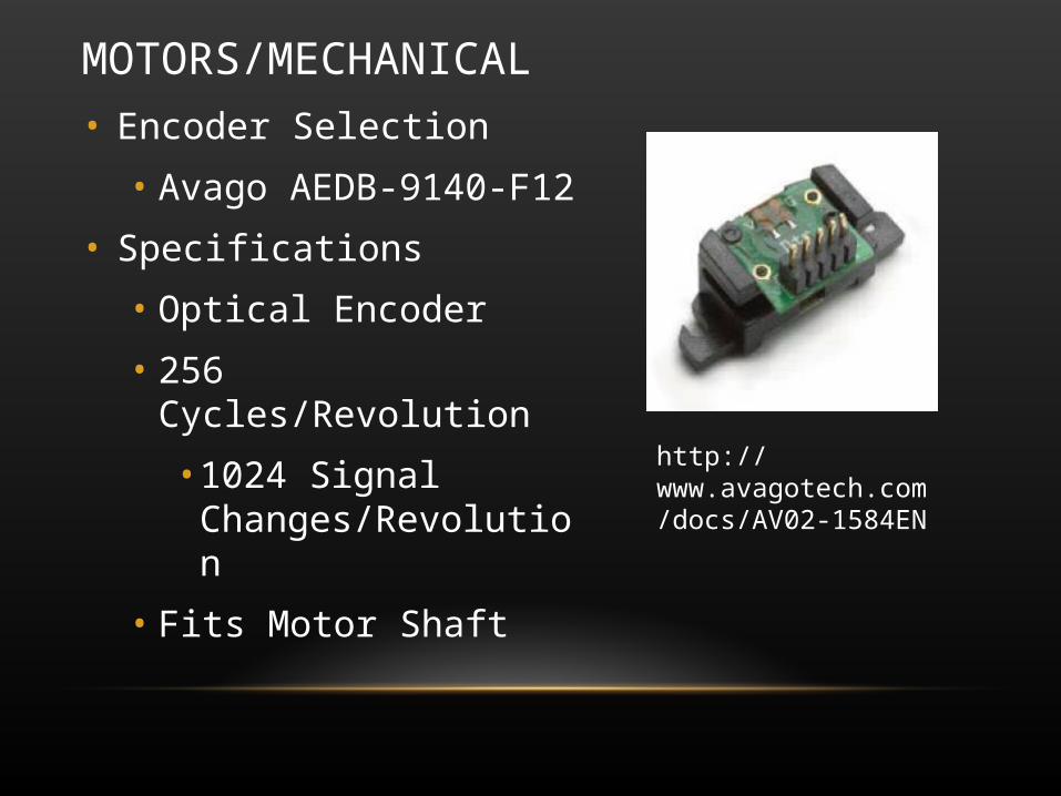
MOTORS/MECHANICAL
• Encoder Selection
• Avago AEDB-9140-F12
• Specifications
• Optical Encoder
• 256 Cycles/Revolution
• 1024 Signal Changes/Revolution
• Fits Motor Shaft
http://www.avagotech.com/docs/AV02-1584EN
MOTORS/MECHANICAL
• H-Bridge Selection
• Texas Instruments DRV8412
• 2 X 3A Full Bridge Continuous Output (2 X 6A peak)
or
• 1 X 6A Full Bridge Continuous Output (1 X 12A peak)
• Controlled With PWM up to 500kHz
• Self-Protection Circuits
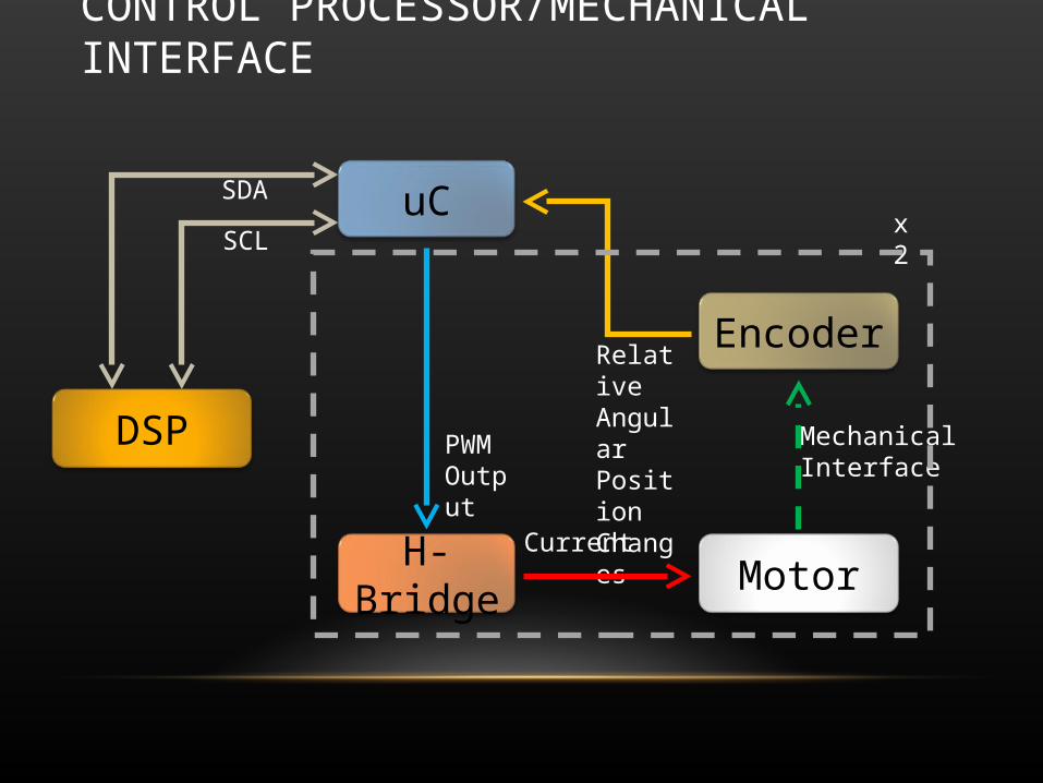
CONTROL PROCESSOR/MECHANICAL INTERFACE
DSP
H-Bridge Motor
MechanicalInterface
EncoderRelative Angular Position Changes
Current
SDA
SCLuC
PWM Output
x2
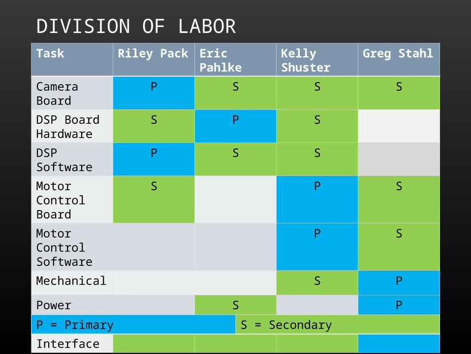
DIVISION OF LABORTask Riley Pack Eric Pahlke Kelly Shuster Greg Stahl
Camera Board P S S S
DSP Board Hardware
S P S
DSP Software P S S
Motor Control Board
S P S
Motor Control Software
P S
Mechanical S P
Power S P
User Interface S S S P
P = Primary S = Secondary
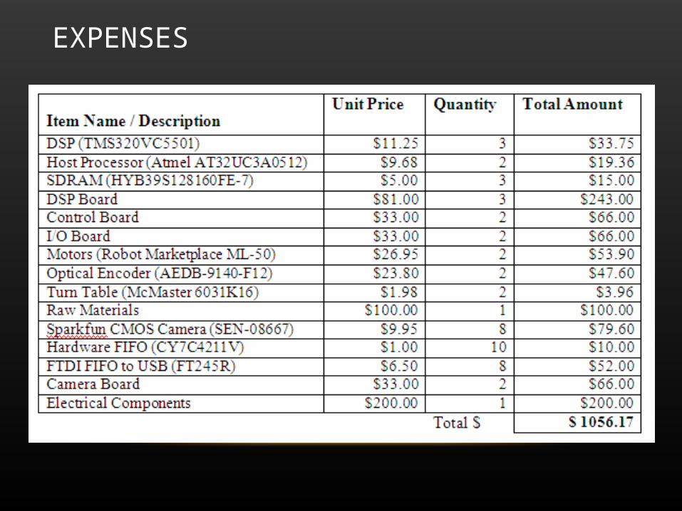
EXPENSES
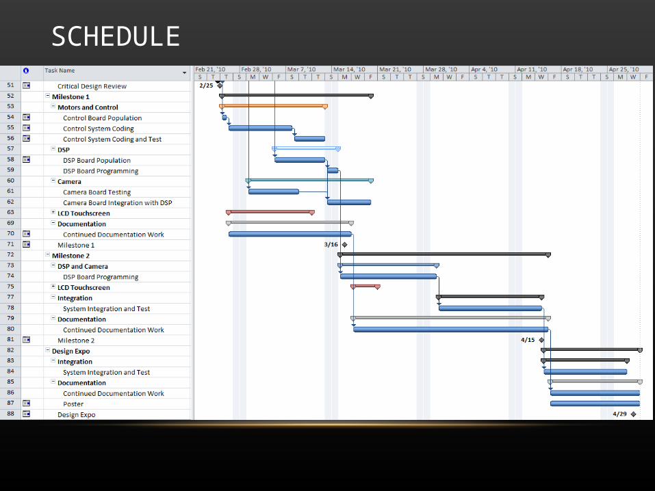
SCHEDULE
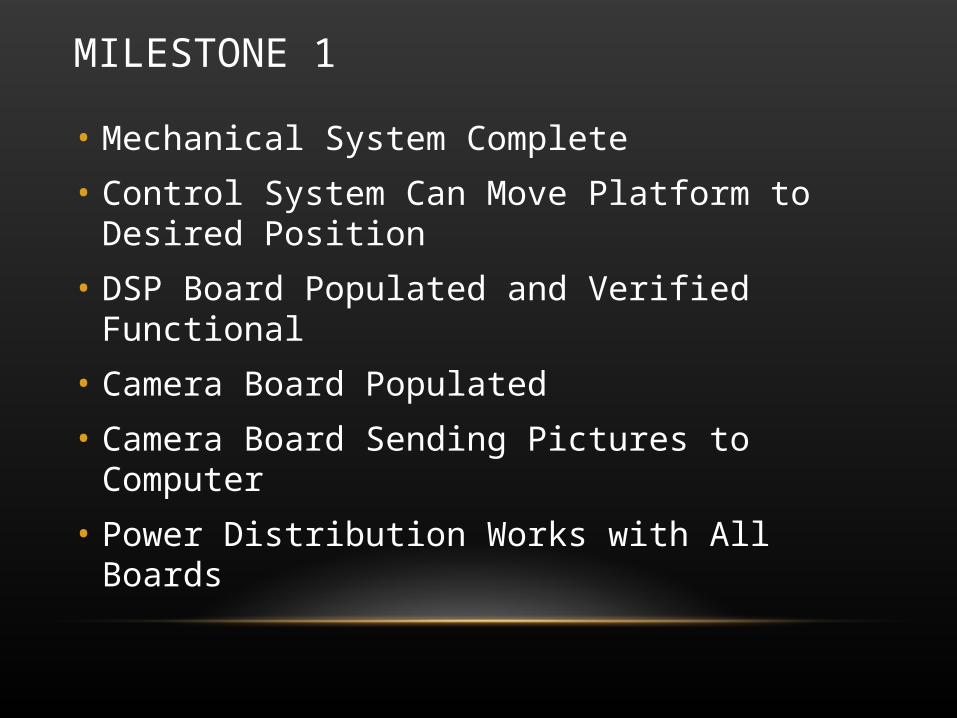
MILESTONE 1
• Mechanical System Complete
• Control System Can Move Platform to Desired Position
• DSP Board Populated and Verified Functional
• Camera Board Populated
• Camera Board Sending Pictures to Computer
• Power Distribution Works with All Boards
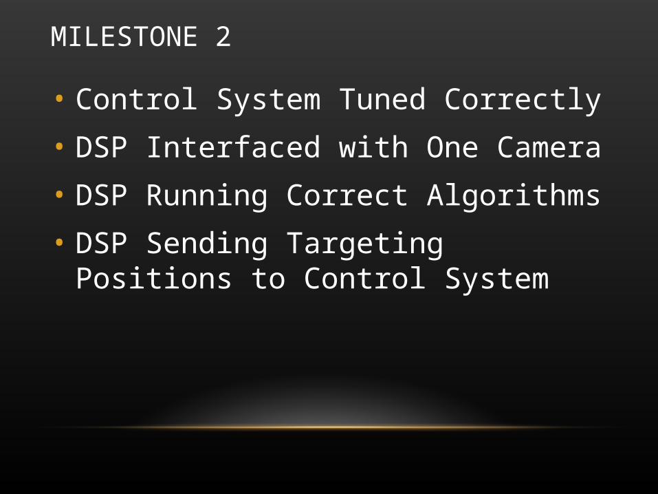
MILESTONE 2
• Control System Tuned Correctly
• DSP Interfaced with One Camera
• DSP Running Correct Algorithms
• DSP Sending Targeting Positions to Control System
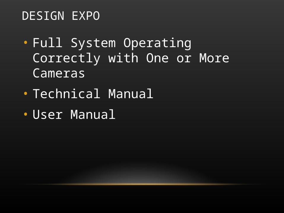
DESIGN EXPO
• Full System Operating Correctly with One or More Cameras
• Technical Manual
• User Manual

Questions?• Kelly Shuster
• Riley Pack
• Eric Pahlke
• Greg Stahl