
Robotic Welding of and I-Beam using a GMAW Gantry System
34
Report for the Department of Transportation PENNDOT Commonwealth of Pennsylvania Robotic Welding of and I-Beam using a GMAW Gantry System August 22, 2009 MAGLEV, Inc. 1100 Industry Road, Box 11 McKeesport, Pennsylvania
Transcript of Robotic Welding of and I-Beam using a GMAW Gantry System

Reportfor the Department of Transportation
PENNDOTCommonwealth of Pennsylvania
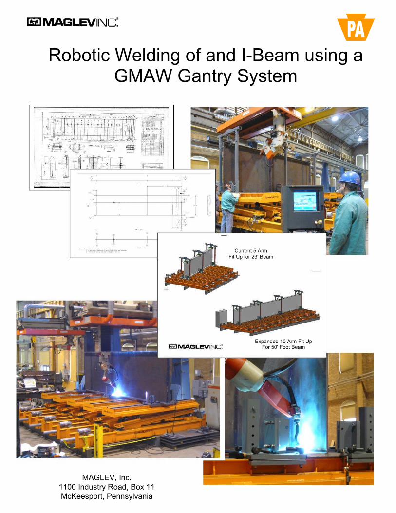
Robotic Welding of and I-Beam using aGMAW Gantry System
August 22, 2009
MAGLEV, Inc.1100 Industry Road, Box 11McKeesport, Pennsylvania
Robotic Welding of and I-Beam using aGMAW Gantry System
Current 5 ArmFit Up for 23' Beam
Expanded 10 Arm Fit UpFor 50' Foot Beam
MAGLEV, Inc.1100 Industry Road, Box 11McKeesport, Pennsylvania
i
Robotic Welding of an I-Beam using aGMAW Gantry System
DisclaimerThis report was prepared as an account of work sponsored by the Commonwealth of Pennsylvania,Department of Transportation, under the Purchase Order No. 4300101953 and performed by MAGLEV, Inc.Neither the Commonwealth of Pennsylvania, nor MAGLEV, Inc. any party acting on behalf of theaforementioned parties (hereinafter referred to as “the Parties”) makes any warranty or representation,express or implied, with respect to the accuracy, completeness, or usefulness of the information contained inthis report. The Parties also assume no liability with respect to the unauthorized use of any information,apparatus, method or process disclosed in this report, which may infringe privately owned rights. Nor do theParties assume any liability with respect to the use of, or for damages resulting from the use of anyinformation, apparatus, method or process disclosed in this report.
Certain information provided in this document is proprietary and is either patented or in the patent process.
MAGLEV, Inc1100 Industry Road, Box 11
McKeesport, PA 15132

ii
Table of Contents
Page
1.0 Background 1
2.0 Program Objective 4
3.0 Technical Approach 53.1 CAD Model 53.2 Material Procurement 53.3 Parameter Development with Tee Section Coupons 53.4 Submerged Arc Weld Comparison 83.5 WPS and PQR 9
4.0 Hold Down Fixtures 14
5.0 Model Beam Development 16
6.0 Full Cross-section Beam 186.1 Beam Fit-Up 186.2 Tack Welding 196.3 Full Welding 20
7.0 Capabilities Analysis 22
8.0 Conclusions 26
Appendix
Appendix A: 3D CAD Drawings (2)

iii
List of Figures
Page
1.0 Automated fit-up table and gantry robot weld system at MAGLEV, Inc. 32.0 3-D CAD model of the project beam 53.0 Schematic of the tee section coupon utilized for weld evaluation 64.0 Illustration of the tee section coupon showing test welds 65.0 Etched cross-section of the GMAW welded tee section 76.0 Etched cross-section of a SAW welded tee section. 87.0 Three position test piece for weld parameter development 98.0 Multipass weld in vertical 1G position for PQR evaluation 109.0 Etched cross-section of a multipass weld in vertical 1G position 1010.0 Multipass weld in vertical 3G position for PQR evaluation 1111.0 Etched cross-section of a multipass weld in vertical 3G position 1112.0 Multipass weld in overhead 4G position for PQR evaluation 1213.0 Etched cross-section of a multipass weld in overhead 4G position 1214.0 One page of the PQR documentation 1315.0 Top section of the hold-down fixtures with an 8-ft long model beam 1416.0 Bottom section of the hold-down fixtures with an 8-ft model beam 1517.0 Illustration of a 2-ft model beam in horizontal position 1618.0 Illustration of an 8-ft model beam being prepared for fabrication 1719.0 Full cross-section 23-ft beam with hold-down fixtures 1820.0 Tack welded full cross-section beam 1921.0 Bottom flange of the 23-ft beam being welded without upper hold-downs 1922.0 GMAW 2F welding of the bottom flange on the 23-ft beam 2023.0 GMAW 4F welding of the top flange on the 23-ft beam 2024.0 Full cross-section 23-ft beam after welding 2125.0 Flat horizontal curvature of a 23-ft I beam in the vertical position using 22
only the hold down fixtures to position and secure the beam26.0 Vertical curvature of a 23-ft I beam achieved from horizontal positioning 23
Using only the hold down fixtures to position and secure the beam27.0 Illustration of the vertical lift capability of the MAGLEV, Inc. computer 23
controlled fit up table28.0 A 23-ft I beam illustrated in compound curvature configuration on the 24
MAGLEV, Inc. computer automated fit-up table29.0 Curvature achieved by hold down fixtures and horizontal extensions 2430.0 Illustration of a 100 ft long beam with a 100 ft horizontal radius 25

1
1.0 Background
During 1999, the Federal Highway Administration and a panel of bridge fabricationtechnology experts from across the United States conducted a major review ofinternational bridge fabrication technology through visits to leading bridge fabricators inEurope and Asia. The objective of the tour was to develop an overview of themanufacturing techniques that are in use internationally for steel bridge fabrication anderection. The trip included visits to modern steel fabrication facilities in Japan, Italy,Germany, and the United Kingdom.
Upon completion of the tour the reviewers concluded that the Japanese and Europeanswere very advanced in the use of computer-aided drawing (CAD) and computer aidedmanufacturing (CAM). They were also advanced in automated recording of inspection,welding variables, and geometric measurements for quality control and virtual assembly.International steel fabricators were consistent in usage of high-performance steels andcoatings, advanced cutting and joining processes including robotics for steelcomponents, members, and structures and advanced design innovation and erection.The tour reviewers concluded that there is a need to modernize structural steelfabrication facilities in the United States if the US fabrication industry were to remainglobally competitive.
A report from a symposium held in 2001 to identify the outcomes of the tour providedsome additional detail of the findings. One of the issues was that steel bridgecomponents for the US market could be fabricated more efficiently and economically ifautomation and robots were used. However, the total fabrication-erection process in theUS is highly decentralized and no fully integrated design-fabrication-erection processexists. With the large number of steel bridges that are fabricated in the US each year,and with the expanding bridge program, advanced processes including computerintegrated manufacturing technology were noted to offer tremendous potential foradvancement of the US fabrication industry.
A summary of observations relating to aspects of automation from that tour together withthe resulting conclusions and implications for change in US practices were identified as:
Elimination of submerged-arc welding and its required fluxhandling systems in favor of automation-friendly GMAW orMIG/MAG welding processes.
Elimination of radiographic inspection in favor of automation-friendly ultrasonic inspection, which would require new definitionsof equipment and operator qualifications and new acceptancespecifications based on fitness for purpose rather than the presentworkmanship requirements.
Use of a single 3D CAD model as the sole source of informationon detailing, shop drawing information, CNC drilling and cuttinginstruction, automated inspection and virtual assembly forgeometry verification.
Possible contractual ties between fabricator and erector in order tofacilitate virtual assembly.

2
Included as part of the symposium, was a discussion of the technology for fabrication ofsteel box girders in Japan. The Japanese use of steel box girders is much moreprevalent than in the US. The CAD/CAM system utilized in the production of thesegirders provided a 3D model of fabrication geometry. Another feature of the fabricationplant is extensive use of robotic welding equipment, processes, and attendantautomation-friendly detailing.
For the shops visited, the amount of utilization of submerged arc welding (SAW) inproportion to gas metal arc, GMAW, welding varied from country to country. Based ondata in the “scanning tour” report, Japan’s usage of GMAW to SAW showed a 90percent preference for GMAW over SAW. In Italy the ratio was 30 percent for GMAWand 70 percent for SAW. The usage as defied for the countries visited during the“scanning tour” report are summarized in the table below.
% SAW % GMAWJapan 10 90Germany 15 85UK 50 50Italy 70 30
As a result of the review, the team also identified six high-priority areas on which theU.S. industry should focus:
Computer aided drawing and computer aided manufacturing Automated recording of inspection, welding variables, and geometric
measurements for quality control and virtual assembly; high-performancesteels and coatings
Automated cutting and joining steel components, members, andstructures
Certification and contracting of steel fabrication and erection Design innovation.
This survey and its finding are of significant interest to MAGLEV, Inc. in its developmentof automated technology for fabrication of guiderail beams for high-speed maglev. Forhigh-speed maglev, more than 3000 uniquely dimensioned trapezoidal box beams withcompound curves will be required. The close tolerance dimensional requirements foreach beam demands that a completely computer integrated system for fabrication beutilized. That system begins with a 3D CAD model and continues with automatedcutting, automated fit up table configuration and robotic welding. The welding systemoffering most promise is GMAW. Interestingly, the needs identified for production ofhigh-speed maglev guiderails parallel those items that are being put into place at themost advanced fabrication shops internationally. Much of this technology is in place atthe MAGLEV, Inc. facilities.
MAGLEV, Inc.’s facilities in McKeesport, Pennsylvania have in-place a computerautomated fit-up table that is integrated with a side entry dual robot gantry weldingsystem. The gantry welding system extends for 35 meters (115 ft), but the automatedfit-up table is currently limited to 6.2 meters (21 ft). The combined system is more

3
advanced than those described in the FHWA “scanning tour” study in its ability todemonstrate the benefits of automated fabrication technology. Additionally, thefabrication capability allows achievement of very high precision dimensional controlwhile producing complex curved box beams. Its capability is directly applicable toproduction of tub girders and conventional I-beams. The systems at the MAGLEV, Inc.facilities are shown in Figure 1.0.
Figure 1.0 Automated fit-up table and gantry robot weld system at MAGLEV, Inc.
The illustration in Figure 1.0 shows the computer automated fit-up table and dual robotgantry welding system in-place at the MAGLEV, Inc. facilities in McKeesport,Pennsylvania. The illustration shows the dual gantry robots being synchronized forsimultaneous welding on opposite sides of a trapezoidal box beam for application todevelopment of high-speed maglev guiderails. Dual robot synchronized weldingprocesses are one mechanism for minimizing distortion from the welding process.Trapezoidal box beams for high-speed maglev are very similar in design andconstruction to trapezoidal tub girders for highway and bridge applications.
4
2.0 Program Objective
The objective of this program was to fabricate a demonstration section of an I-beamgirder for application in a transportation environment. This girder was to be a prototypegirder capable of being produced with designed-in curves and be approximately 20-ft inlength. The beam selected for this program, however, was a straight section beam ofheight 6 ft 9 in and length 23 ft.
Satisfaction of this objective was pursued by use of advanced precision fabricationtechnology employing gantry mounted dual robots and GMAW process to demonstratethe system capability in production of a current design I-beam utilized by PENNDOT.The beam size was to be full cross-section, but of abbreviated length to match to thetable capabilities currently in-place. The welding technology to be employed wasGMAW with all welds performed utilizing only one initial fit-up. The welds were to behorizontal 2F, vertical 3F and overhead 4F welds. Standard specifications applicable toPENNDOT were to be achieved in the process.

5
3.0 Technical Approach
3.1 CAD Model
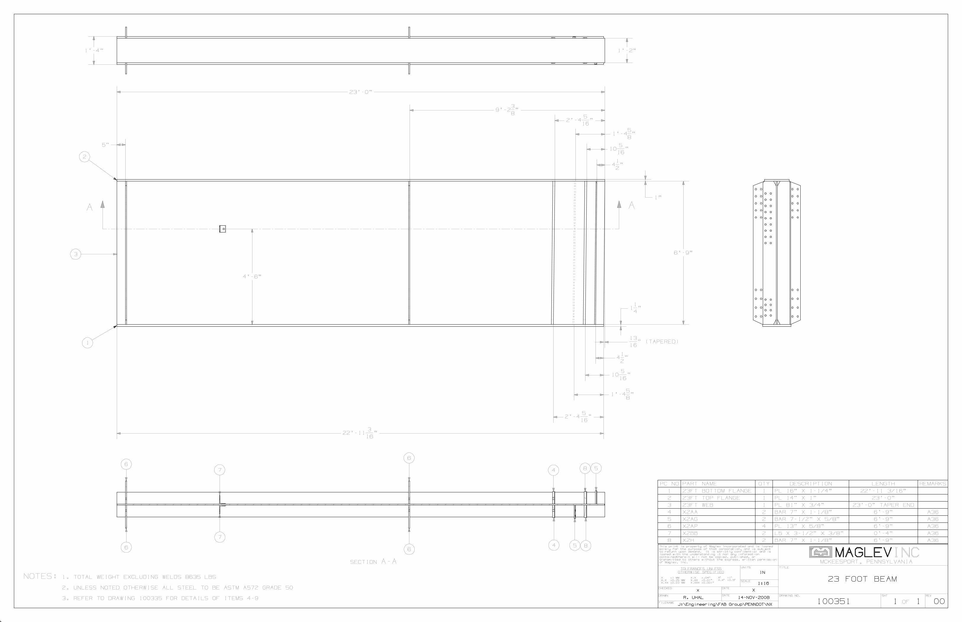
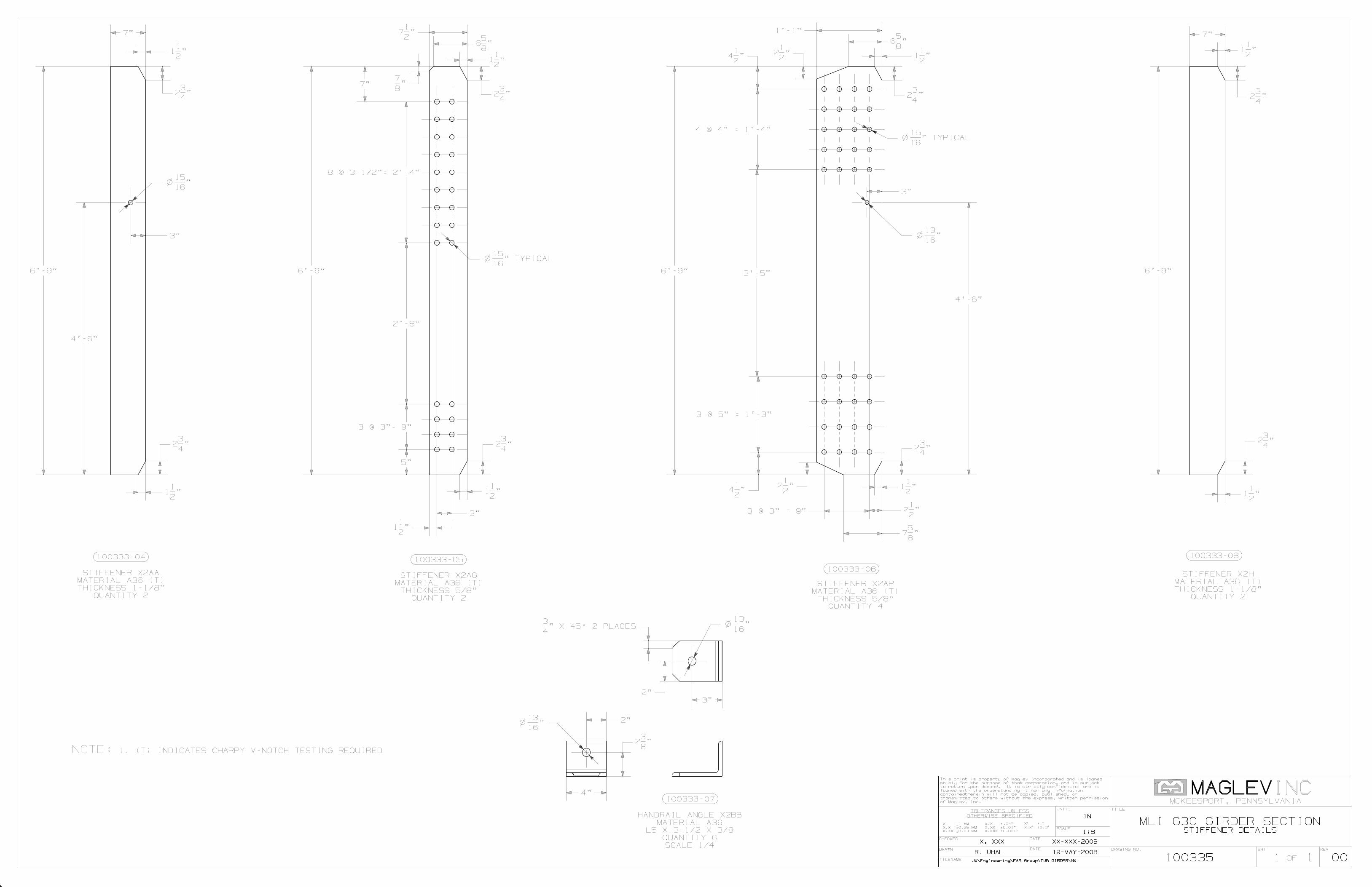
The first step in the performance of the overall task was to secure a drawing of a typicalI-beam utilized by PENNDOT. The District Bridge Engineer provided that drawing of acommon use beam for PENNDOT bridge construction projects. That drawing wasconverted to a CAD model with drawing and appropriate assessments for a Bill ofMaterial were made. Afterwards, the necessary materials were procured. A copy of theCAD drawing is given in Appendix A. The 3D CAD model of the project beam is shownin Figure 2.0.
Figure 2.0 3D CAD model of the project beam.
3.2 Material Procurement
Components were arranged by computer lay out from the CAD drawing so that optimummaterial size procurement and utilization were achieved. After optimization of the CADcomponent layout, material conforming to the ASTM Specification A572 Grade 50 wasprocured in sufficient quantities to produce the final product and the prerequisite modelbeams and developmental tee section coupons.
3.3 Parameter Development with Tee Section Coupons
A series of tee-section coupons of the specified material chemistry and thicknesses wereassembled by tack welding. Welding parameters were developed using these teesections. An isometric schematic of a tee section coupon is shown in Figure 3.0. Weldparameters were also evaluated by use of a three-position test piece shown in Figure7.0. Welds were made with 5/16 in leg size and with a 3/32 in tack. Weld over tackedsection are shown in Figure 4.0.
Sections of the tee that contained the basic weld, basic tack and the weld over tack werecut from the test coupon and etched for further examination of weld soundness.Examination of those etched coupons showed that the final fillet weld completely re-melted the tack weld.

6
Figure 3.0 Schematic of the tee section coupon utilized for weld evaluation.
The illustration shown in Figure 4.0 shows the different welding situations. The areadesignated on the section noted by “T” was for the 5/32 in tack weld only. The regionnoted by “W” was for the 5/16 in weld only and the segment noted by “T + W” was for thesegment where the weld was made over the tack. The tack was 5/32 in (4mm) x 3 inlong spaced at 21 in on center on the test beam.
Figure 4.0 Illustration of the tee section coupon showing test welds.
After tacking and welding of the tee-section coupons, segments were sectioned asshown in Figure 4.0 so that each distinct tack, weld or combination could be furtherexamined. Each segment was rough polished, etched and examined visually. Theetched segment for the weld and the weld over tack is shown in Figure 5.0.

Figure 5.0
The illustrationsections showdesignated in t“WB2”. The ta
Fillet welds onThe welding paand those paraparameters depresented in th
S
5/32 Tack
5/16 Weld
Weld/Tack
* Amperage va
7
Etched cross-section of the GMAW welded tee section.
of Figure 5.0 shows the etched cross-sections of the GMAW welded teeing the 5/16-inch over the 5/32-inch tack and the 5/16 in weld without tackhe illustration as “T&WF”. The weld bead without tack is designated asck weld has been completely re-melted.
the tee-section coupons were produced in the 2F, 3F and 4F positions.rameters were developed from evaluation of these tee-section couponsmeters were established as the preliminary WPS. The weldingveloped from the tee-section coupons for the various position welds aree tables below.
Weld Parameters for Horizontal 2F Welds
peed Weave Gas Wire Amp Volt Wire Feedipm Freq in-1 Ar/CO2 Dia. Speed ipm
26 0 85/15 0.052 170 22 170
13 125 85/15 0.052 310* 27.5 340
13 125 85/15 0.052 310* 27.4 340
ried +/- 10 % with weave
8
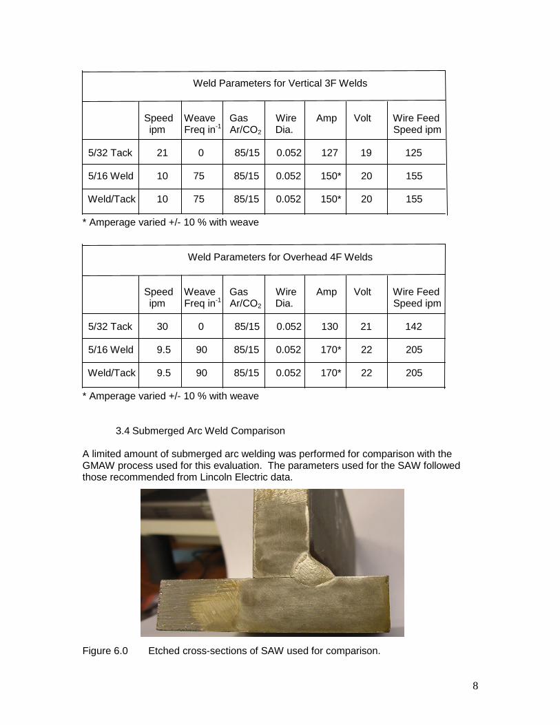
Weld Parameters for Vertical 3F Welds
Speed Weave Gas Wire Amp Volt Wire Feedipm Freq in-1 Ar/CO2 Dia. Speed ipm
5/32 Tack 21 0 85/15 0.052 127 19 125
5/16 Weld 10 75 85/15 0.052 150* 20 155
Weld/Tack 10 75 85/15 0.052 150* 20 155
* Amperage varied +/- 10 % with weave
Weld Parameters for Overhead 4F Welds
Speed Weave Gas Wire Amp Volt Wire Feedipm Freq in-1 Ar/CO2 Dia. Speed ipm
5/32 Tack 30 0 85/15 0.052 130 21 142
5/16 Weld 9.5 90 85/15 0.052 170* 22 205
Weld/Tack 9.5 90 85/15 0.052 170* 22 205
* Amperage varied +/- 10 % with weave
3.4 Submerged Arc Weld Comparison
A limited amount of submerged arc welding was performed for comparison with theGMAW process used for this evaluation. The parameters used for the SAW followedthose recommended from Lincoln Electric data.
Figure 6.0 Etched cross-sections of SAW used for comparison.
The weld bead penetration and the heat affected zone from the SAW process can becompared to that from the GMAW process by comparison of the sections and etchedbeads and heat affected zones illustrated in Figure 5.0 and Figure 6.0. The weldpenetration and heat-affected zones are similar. Both meet acceptable fillet weldprofiles as outlined in AASHTO/AWS D1.5M/D1.5:2002 section 5.19.
3.5 WPS and PQR
A WPS was developed based on the weld parameters developed from the tee sectioncoupons. The WPS was developed in accordance to PENNDOT specification usingAASHTO/AWS D1.5M/D1.5:2008. That test coupon for the PQR was performed in thepresence of a PENNDOT weld inspection official. Evaluation of the weld was performedby a local approved testing facility. After the desired parameters for welding wereselected, a preliminary WPS was developed and arrangements were made for aPENNDOT inspector to review the selected parameters and to be present when the testsegments for the PQR evaluation were welded.
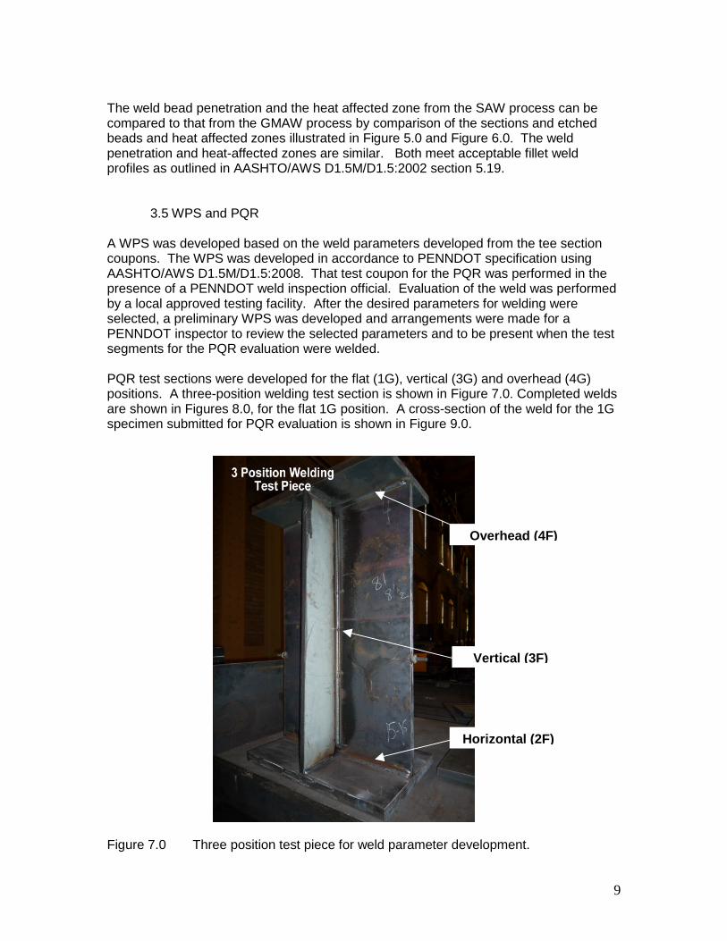
PQR test sections were developed for the flat (1G), vertical (3G) and overhead (4G)positions. A three-position welding test section is shown in Figure 7.0. Completed weldsare shown in Figures 8.0, for the flat 1G position. A cross-section of the weld for the 1Gspecimen submitted for PQR evaluation is shown in Figure 9.0.
Figure 7.0 Three position test piece for weld parameter de
H
Overhead (4F)
Vertical (3F)
9
velopment.
orizontal (2F)
10
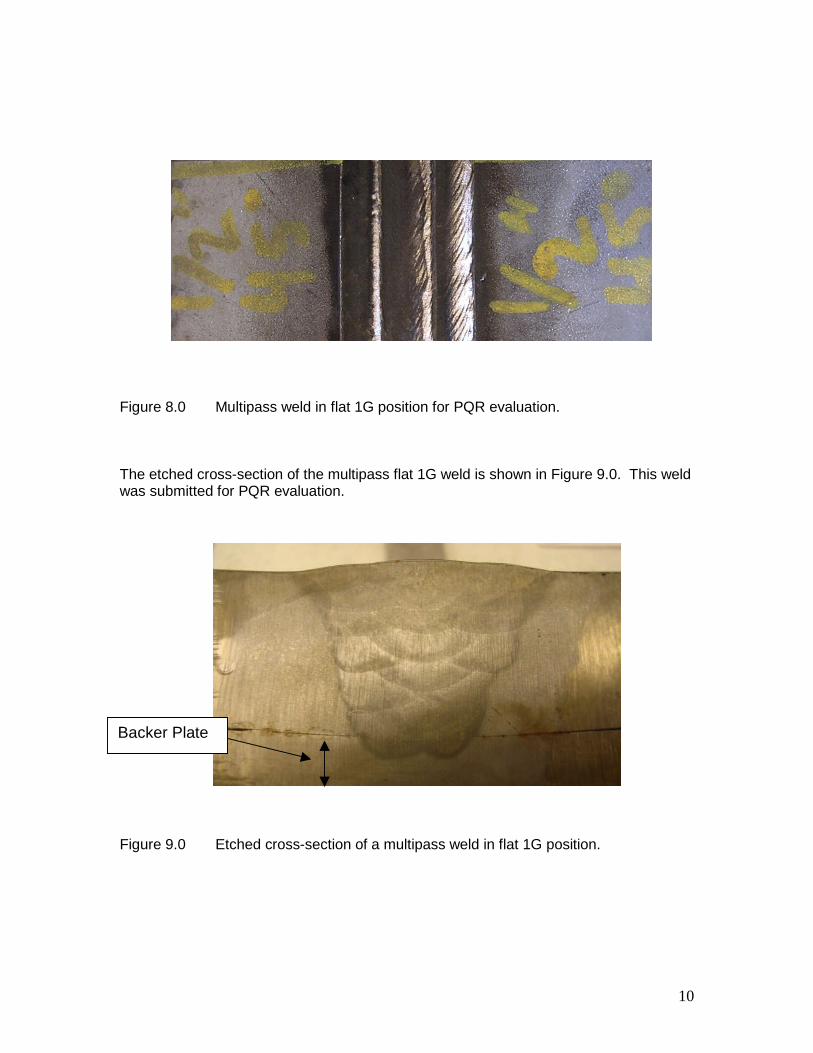
Figure 8.0 Multipass weld in flat 1G position for PQR evaluation.
The etched cross-section of the multipass flat 1G weld is shown in Figure 9.0. This weldwas submitted for PQR evaluation.
Figure 9.0 Etched cross-section of a multipass weld in flat 1G position.
Backer Plate
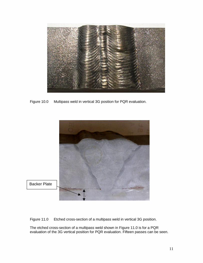
Figure 10.0
Figure 11.0
The etchedevaluation o
Backer Pla
Multipass weld in vertical 3G position for PQR evaluation.
Et
crossf the
te
11
ched cross-section of a multipass weld in vertical 3G position.
-section of a multipass weld shown in Figure 11.0 is for a PQR3G vertical position for PQR evaluation. Fifteen passes can be seen.

Figure 12.0
Figure 13.0
The etchedevaluation
Backer Pl
12
Multipass weld in 4G overhead position for PQR evaluation.
Etched cross-section of a multipass weld in overhead 4G position.
cross-section of a multipass weld in the 4G overhead position for PQRis shown in Figure 13.0. Fifteen passes can be seen.
ate
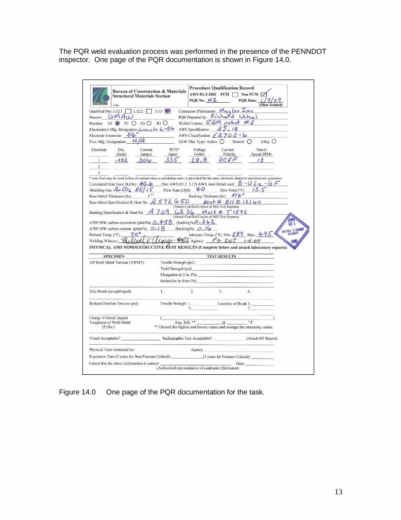
The PQR weld evaluation process was performed in the presence of the PENNDOTinspector. One page of the PQR documentation is shown in Figure 14.0.
Figure 1
13
4.0 One page of the PQR documentation for the task.
14
4.0 Hold Down Fixtures
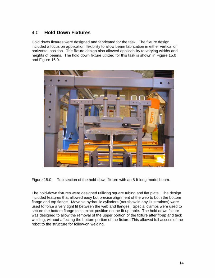
Hold down fixtures were designed and fabricated for the task. The fixture designincluded a focus on application flexibility to allow beam fabrication in either vertical orhorizontal position. The fixture design also allowed applicability to varying widths andheights of beams. The hold down fixture utilized for this task is shown in Figure 15.0and Figure 16.0.
Figure 15.0 Top section of the hold-down fixture with an 8-ft long model beam.
The hold-down fixtures were designed utilizing square tubing and flat plate. The designincluded features that allowed easy but precise alignment of the web to both the bottomflange and top flange. Movable hydraulic cylinders (not show in any illustrations) wereused to force a very tight fit between the web and flanges. Special clamps were used tosecure the bottom flange to its exact position on the fit up table. The hold down fixturewas designed to allow the removal of the upper portion of the fixture after fit-up and tackwelding, without affecting the bottom portion of the fixture. This allowed full access of therobot to the structure for follow-on welding.
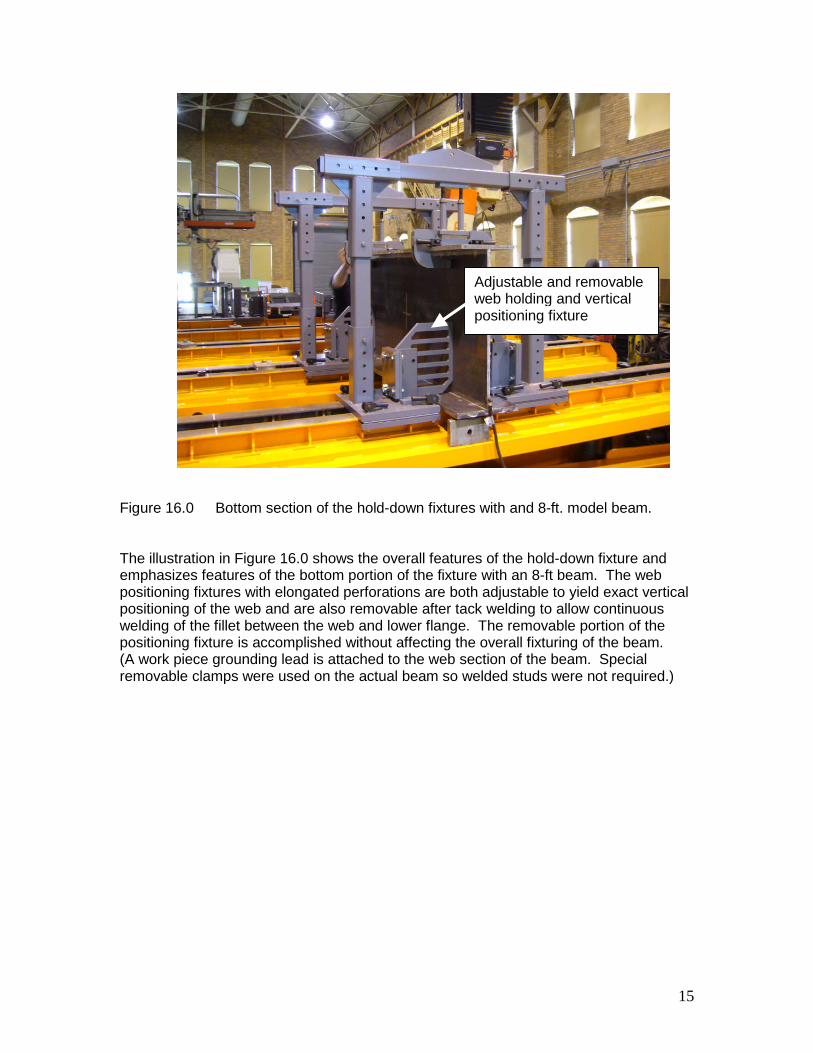
Figure 1
The illusemphaspositionpositionweldingposition(A workremovab
15
6.0 Bottom section of the hold-down fixtures with and 8-ft. model beam.
tration in Figure 16.0 shows the overall features of the hold-down fixture andizes features of the bottom portion of the fixture with an 8-ft beam. The webing fixtures with elongated perforations are both adjustable to yield exact verticaling of the web and are also removable after tack welding to allow continuousof the fillet between the web and lower flange. The removable portion of theing fixture is accomplished without affecting the overall fixturing of the beam.piece grounding lead is attached to the web section of the beam. Specialle clamps were used on the actual beam so welded studs were not required.)
Adjustable and removableweb holding and verticalpositioning fixture

5.0 Model beam Development
An interim step in beam fabrication was incorporated in the task. This interim steprelated to the fabrication of sub-size beams that were utilized to establish weldingprocess steps prior to fabrication of the full cross-section beam. A very small beamapproximately two feet long and three feet high was first fabricated using the developedprocess and this was followed by fabrication of two beams of eight feet in length tomodel the process. The smaller model is shown in Figure 17.0 with the model beam inthe horizontal position and the larger model beam is shown in the vertical position inFigure 18.0.
Figur
A 2-ftwith spositiproceflippinproce
16
e 17.0 Illustration of a 2-ft model beam in the horizontal position.
. long model beam was fabricated in the horizontal position to make a comparisonimpler fixturing that would be associated with the horizontal positioning. Thison offered some fixturing advantages but requires additional fixturing and handlingss when the beam is flipped to weld the alternate side. Additional handling forg and re-fixturing of the beam would be required when submerged arc weldingsses were utilized.

Figure 1
Fabricatbe accoprocesswhether
17
8.0 An 8-ft long model beam being prepared for fabrication in the verticalposition.
ion with the beam in the vertical position with modified hold down fixturing canmplished with GMSW process where vertical 3F and overhead 4F weldinges are employed. This allows a single fixturing operation to be used for all weldsin flat or out of-position welds.

18
6.0 Full Cross-section Beam
After satisfactory development of the process through the use of model beams, the fullcross-section but abbreviated length I-beam was fit-up and fabricated in the verticalposition. The beam measurements are given in Appendix A.
6.1 Beam Fit Up
An illustration of the full cross-section beam is shown mounted on the fit-up table invarious steps of welding in Figures 19.0 - 24.0.
Figure 19.0 Full cross-section 23-ft beam in place with hold down fixtures.
The illustration in Figure 19.0 shows the complete hold-down fixture in place for fit upand follow-on tack welding.
6.2 Tack Welding
Figure 2
Tack weThe tackpercentimpactiv
Figure 2
19
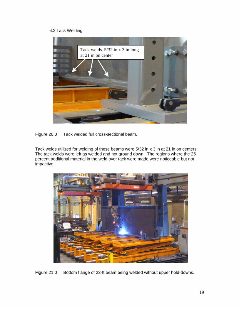
0.0 Tack welded full cross-sectional beam.
lds utilized for welding of these beams were 5/32 in x 3 in at 21 in on centers.welds were left as welded and not ground down. The regions where the 25
additional material in the weld over tack were made were noticeable but note.
1.0 Bottom flange of 23-ft beam being welded without upper hold-downs.
3 in tack welds21 in on center
Tack welds 5/32 in x 3 in longat 21 in on center
6.3 Full Welding
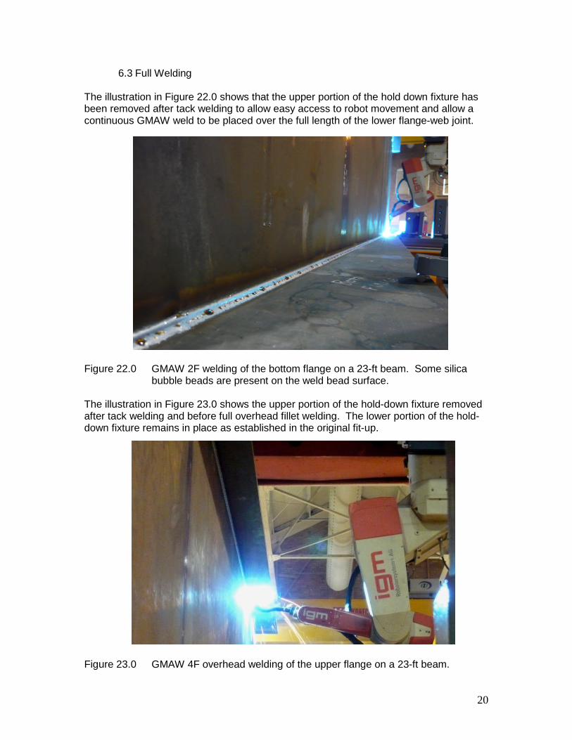
The illustration in Figure 22.0 shows that the upper portion of the hold down fixture hasbeen removed after tack welding to allow easy access to robot movement and allow acontinuous GMAW weld to be placed over the full length of the lower flange-web joint.
Figure 22
The illustrafter tackdown fixtu
Figure 23
.0 GMAW 2F welding of the bottom flange on a 23-ft beam. Some silicabubble beads are present on the weld bead surface.
ation in Figure 23.0 shows the upper portion of the hold-down fixture removedwelding and before full overhead fillet welding. The lower portion of the hold-re remains in place as established in the original fit-up.
20
.0 GMAW 4F overhead welding of the upper flange on a 23-ft beam.
21
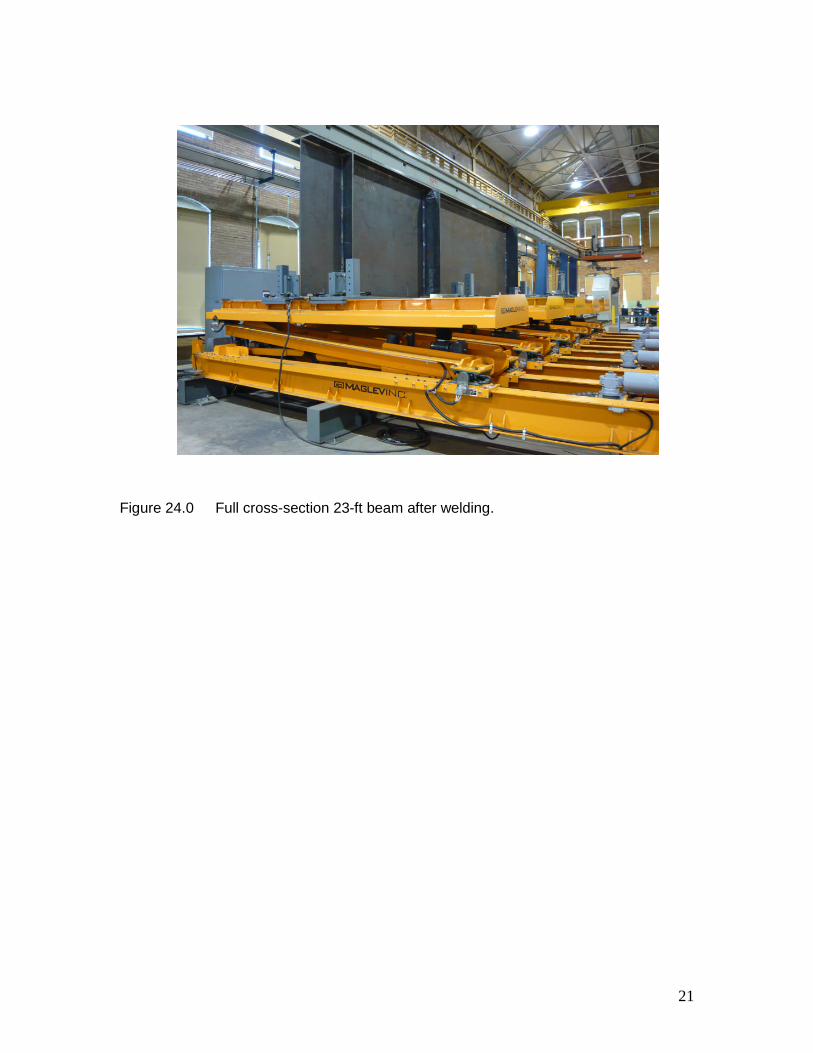
Figure 24.0 Full cross-section 23-ft beam after welding.
22
7.0 Capabilities Analysis
Equipment capabilities and fabrication integration currently in place at MAGLEV, Inc.’sMcKeesport facilities meet and exceed the needs outlined in the FHWA “scanning tour”report. This includes CAD integrated computer automated fit up table combined with thegantry mounted dual robot GMAW welding. The combined equipment, though currentlylimited in length capability, will facilitate welding straight or complex curved beams.
The equipment capability has been focused toward the development of guiderails forhigh-speed maglev that require precise configuration and rapid reconfiguration of the fitup table directly from a digitized computer database that include compound curvatureswith cant (twist). The approach at MAGLEV, Inc. is for a totally computerized fabricationprocess from CAD design configuration to final installation for operational service. Whiletotal integration is not yet in place, an objective is to make that total integration system ademonstrated reality with longer length capability table and total system integration.
CAD generated design configurations applied to a 23-ft beam have been developed andfitted to the existing equipment capability. Some examples of the curved beam designfitted onto the existing 23-ft fit up table are shown in Figures 25.0 – 28.0.
Figures 25.0 and 26.0 show a curved beam fitted onto the existing fit-up table in both thevertical and horizontal positions. While these are only shown for a 23-ft long beam, theyprovide a pictorial view of the curved beam fabrication capability.
The usable table width design capability is currently 15 feet 10 inches, but the individualunits of the table are designed to be adjusted in the width position by an additional onemeter (3 ft 4 in) of horizontal movement increasing the total horizontal curvaturecapability of the fit up table system.
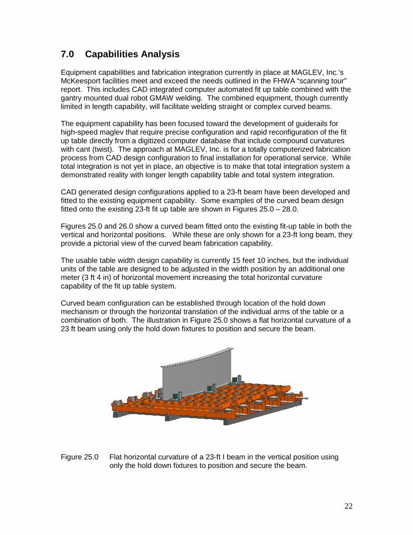
Curved beam configuration can be established through location of the hold downmechanism or through the horizontal translation of the individual arms of the table or acombination of both. The illustration in Figure 25.0 shows a flat horizontal curvature of a23 ft beam using only the hold down fixtures to position and secure the beam.
Figure 25.0 Flat horizontal curvature of a 23-ft I beam in the vertical position usingonly the hold down fixtures to position and secure the beam.
This beam is shown in the vertical position that allows the beam to be totally fit, tackedand welded in the upright position without any flipping of the beam. Straight or curvedbeams can be fabricated
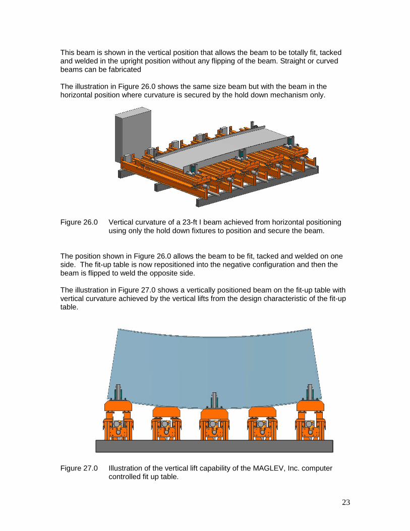
The illustration in Figure 26.0 shows the same size beam but with the beam in thehorizontal position where curvature is secured by the hold down mechanism only.
Figure 26.0 Vertical curvature of a 23-ft I beam achieved from horizontal positioningusing only the hold down fixtures to position and secure the beam.
The position shown in Figure 26.0 allows the beam to be fit, tacked and welded on oneside. The fit-up table is now repositioned into the negative configuration and then thebeam is flipped to weld the opposite side.
The illustration in Figure 27.0 shows a vertically positioned beam on the fit-up table withvertical curvature achieved by the vertical lifts from the design characteristic of the fit-uptable.
Figure 27
23
.0 Illustration of the vertical lift capability of the MAGLEV, Inc. computercontrolled fit up table.

The lift capability of an individual arm is up to one meter (3 ft 4 in). Lifts on the otherarms can be configured very precisely by computer controlled automated processesemployed on the MAGLEV, Inc. system.
Figure 28
The illustrtable for fconfigurebeam. Coand horiz
The illustrconfigura
Figure 29
24
.0 A 23-ft I beam illustrated in compound curvature configuration on theMAGLEV, Inc. computer automated fit-up table.
ation shown in Figure 28.0 shows the capability of the MAGLEV, Inc. fit upabricating I beams with compound curvatures. The table can also bed with twist that will allow cants of up to 25 degrees to be incorporated into thempound curves with cant are developed using a combination of the vertical
ontal positioning of the top segment of the arms of the fit-up table.
ation in Figure 29.0 shows a vertically mounted I beam in a curvedtion with the curve being secured by the hold down fixture mechanisms.
.0 Vertical beam curvature achieved by hold down structures and horizontalextensions of the individual arms of the fit-up table.
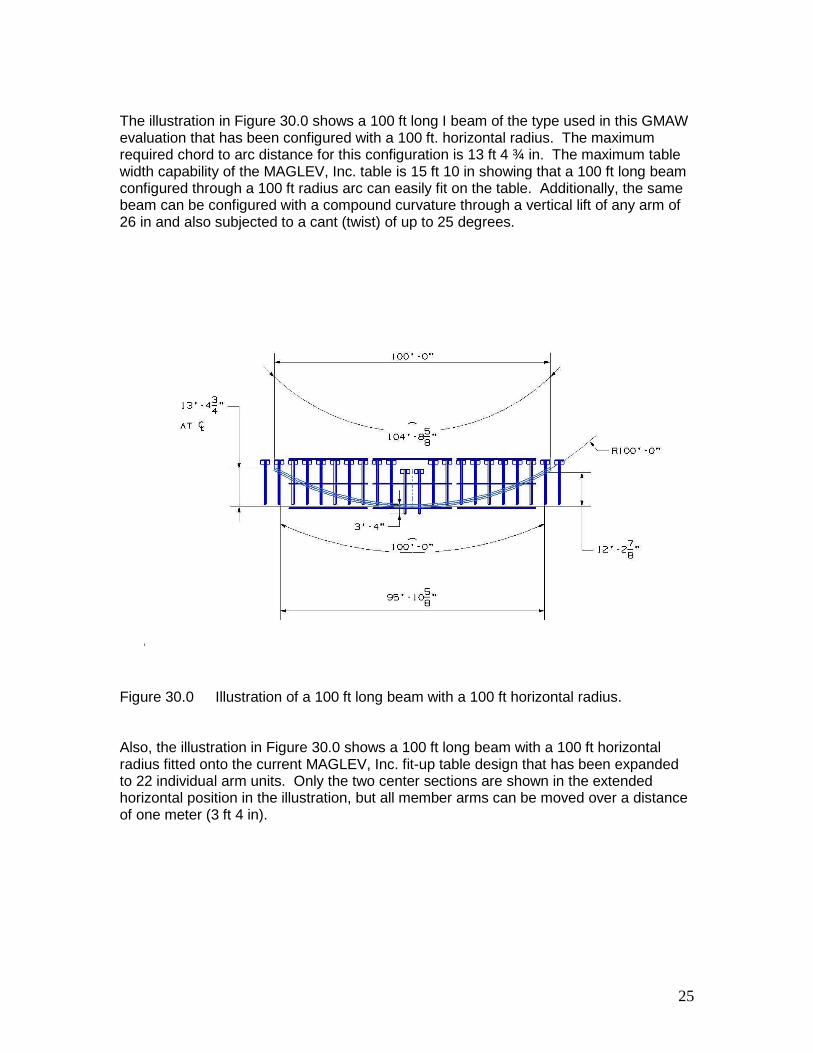
The illustration in Figure 30.0 shows a 100 ft long I beam of the type used in this GMAWevaluation that has been configured with a 100 ft. horizontal radius. The maximumrequired chord to arc distance for this configuration is 13 ft 4 ¾ in. The maximum tablewidth capability of the MAGLEV, Inc. table is 15 ft 10 in showing that a 100 ft long beamconfigured through a 100 ft radius arc can easily fit on the table. Additionally, the samebeam can be configured with a compound curvature through a vertical lift of any arm of26 in and also subjected to a cant (twist) of up to 25 degrees.
Fig
Alsradtohoof
25
ure 30.0 Illustration of a 100 ft long beam with a 100 ft horizontal radius.
o, the illustration in Figure 30.0 shows a 100 ft long beam with a 100 ft horizontalius fitted onto the current MAGLEV, Inc. fit-up table design that has been expanded
22 individual arm units. Only the two center sections are shown in the extendedrizontal position in the illustration, but all member arms can be moved over a distanceone meter (3 ft 4 in).
26
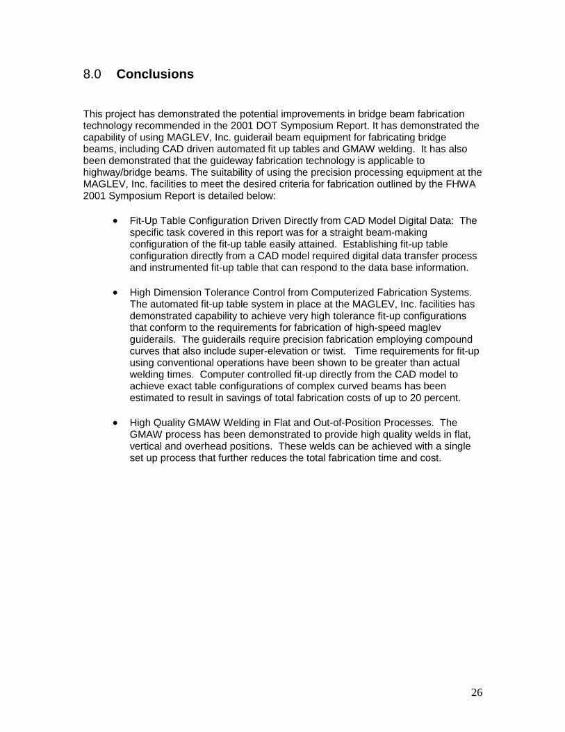
8.0 Conclusions
This project has demonstrated the potential improvements in bridge beam fabricationtechnology recommended in the 2001 DOT Symposium Report. It has demonstrated thecapability of using MAGLEV, Inc. guiderail beam equipment for fabricating bridgebeams, including CAD driven automated fit up tables and GMAW welding. It has alsobeen demonstrated that the guideway fabrication technology is applicable tohighway/bridge beams. The suitability of using the precision processing equipment at theMAGLEV, Inc. facilities to meet the desired criteria for fabrication outlined by the FHWA2001 Symposium Report is detailed below:
Fit-Up Table Configuration Driven Directly from CAD Model Digital Data: Thespecific task covered in this report was for a straight beam-makingconfiguration of the fit-up table easily attained. Establishing fit-up tableconfiguration directly from a CAD model required digital data transfer processand instrumented fit-up table that can respond to the data base information.
High Dimension Tolerance Control from Computerized Fabrication Systems.The automated fit-up table system in place at the MAGLEV, Inc. facilities hasdemonstrated capability to achieve very high tolerance fit-up configurationsthat conform to the requirements for fabrication of high-speed maglevguiderails. The guiderails require precision fabrication employing compoundcurves that also include super-elevation or twist. Time requirements for fit-upusing conventional operations have been shown to be greater than actualwelding times. Computer controlled fit-up directly from the CAD model toachieve exact table configurations of complex curved beams has beenestimated to result in savings of total fabrication costs of up to 20 percent.
High Quality GMAW Welding in Flat and Out-of-Position Processes. TheGMAW process has been demonstrated to provide high quality welds in flat,vertical and overhead positions. These welds can be achieved with a singleset up process that further reduces the total fabrication time and cost.

1
APPENDIX A


![GMAW chapter22[1]](https://static.fdocuments.in/doc/165x107/577d22881a28ab4e1e97a08e/gmaw-chapter221.jpg)

