Robotic Timber Construction - Study on Robotic Fabrication ...

Robotic fabrication of stone assembly details
Inés Ariza1, 3, T. Shan Sutherland2, 3, James B. Durham3, Caitlin T. Mueller1, Wes McGee2, 4, Brandon Clifford1, 4
1 Massachusetts Institute of Technology, 2 University of Michigan, 3 Quarra Stone, 4 Matter
Design Keywords: digital fabrication, robotic stone carving, assembly detail, metal casting, free-form shell structure, assembly sequence Abstract Recently, digital design and fabrication developments in free-form shell structures have flourished, allowing for novel uses of ancient techniques such as stone carving, which can be implemented with contemporary robotic fabrication to customize geometries of discrete parts. The newly available opportunities to digitally design, simulate, and fabricate individually unique shell pieces, or voussoirs, has called into question the modern approach of standardization of components and its complementary ubiquitous joining solutions. However, a significant challenge in building free-form geometries in stone arises from the required accuracy of the joining techniques to accommodate large number of unique voussoirs. One solution to this problem is supporting the pieces in place by means of scaffolding structures while they are tested for fit and manually trimmed (Rippmann et al. 2016). While this is the predominant solution and has produced remarkable structures, the scaffolding results in a costly operation executed by a separate and differently skilled group of fabricators. This research proposes an alternative assembly strategy for free-form stone shells that relies on a local joining solution at each step of the assembly sequence. Integrating structural analysis with the ability of robots to perform custom non-repetitive stone carving and the ability of cast metal to be formed with great geometric flexibility, the methodology aims to minimize the use of wasteful scaffolding while allowing the adjustable fitting of the resultant voussoirs. The approach incorporates a 5-step process from design to assembly: At each stage of the simulated assembly sequence, finite element analysis is performed to define the exact location, direction and size of the joint needed to stabilize each unique voussoir through tension, compression, bending, or shear. The joint geometry is then optimized to take local forces and is machined to a 1.5mm tolerance with a robotic arm. The assembly is executed by rings following a specific assembly sequence, registering each piece with a custom adjustable drift pin. This process accommodates to the precision needed at each stage of the assembly, allowing deeper or shallower registration in each course and permitting pieces to move and correct until all pieces are fitted in place. The final joint is cast in-situ with a melting point metal, fixing the pieces to their final position. The final results show the specialized assembly joint at each step of the assembly sequence. Two marble prototypes serve as proof-of-concept of the methodology and suggest that the integration of structural evaluation with an adjustable assembly approach enabled by robotic fabrication can reduce the need of scaffolding in the construction of free-form shell structures.

1. Research Aims and Objectives This work follows an important body of work in the past decade focused on the design of global surface geometries for compression-only structural behavior. For example, studies in thrust network analysis have made possible the design and computation of complex unreinforced free-form shell structures that work purely under axial forces once they are completely assembled (Block, 2009). Recent built projects have shown that while these structures are possible to construct with standard CNC fabrication tools and demonstrate efficient structural behavior as expected, a major challenge of building these structures relies on effective assembly strategies during construction to handle tolerance (Rippmann et al., 2016). A second key challenge is the management of formwork, which is structurally necessary to hold individual voussoirs in place until the structure is stable, which is sometimes not until the final stone is placed. These challenges are important to address in order for efficient, geometrically expressive masonry shell structures to play a larger role in the contemporary architectural fabrication landscape alongside conventional steel, concrete, and timber structures. In response, the research presented here offers a new approach for the fabrication and assembly for free-form masonry shell structures that can be built with less error and less falsework. Made possible through a computational workflow that simulates structural behavior during assembly instead of only after a structure is completed, the approach employs cast-metal joining details that bring ancient stonework techniques into the digital age with customized, mechanically responsive geometries. 2. Research Context New agendas for stone carving Correlating forces (physics) and form (geometry) in 3D, thrust network analysis and accessible physics simulation environments based on dynamic relaxation have extended historical structural form-finding methods into new versatile digital design workflows (Block, 2009; Rippmann et al., 2011; Piker, 2013). One of the results of the availability of these new geometrical exploration approaches has been a renewed interest by designers into historical techniques such as stone carving (Lachauer et al., 2011; Rippmann et al., 2016; Clifford et al., 2015; Kaczynski et al., 2011). Construction of discrete element structures Most of the current research efforts in discrete element structures have focused in the production of geometrically challenging thinner structures that perform efficiently once they are finally assembled. These efforts have disregarded taking into account the forces intervening during assembly, assuming that the construction of these structures could be solved by external means such as scaffolding, chains or ropes (Deuss et al., 2014). Stone detail precedents and methods Two types of detail precedents informed this research. The first is the historic process of carving a detail geometry into stone and direct casting metal into that geometry. This detail is often

embedded inside the thickness of stone and not visible. The motivation of this detail is to resist a possible future force, be it settling or earthquake. These details are unconstrained by the mass of stone, but rather by the properties of metal shaping or casting and the carving tools (Leroy, 2015). These constraints are expanded upon in section 4. The second detail precedent is a procedural one. For instance, Inca stonework carries vestigial details which hint at the sequence with which a wall was constructed. Each detail dedicated to the particular moment of assembly and its relation to previously placed stones. This concept can be seen not only in the way the stones notch into each other, but also nubs used to place the stones. This research seeks to conflate these two detail concepts in order to incorporate procedural and sequential structural analysis to inform detail locations. The following locations are respondent not only to the global conditions, but to the discrete conditions of the in-progress assembly (Protzen, 1993).
Figure 1. (a) Cavities that were carved into stones and fit with steel joints during the Angkorian era (Mitch Hendrickson, Source: Cambodia Daily), and (b) Inca wall assembly detail (Brandon Clifford). 3. Research Questions This project proposes to look at the problem of assembly from the standpoint of integrating computation, analysis and simulation during the design phases. The motivation of the research

is to develop an integrated workflow which encompasses design, fabrication, and assembly of discrete element structures by leveraging the possibilities of digital fabrication methods. 4. Research Methods The assembly method in this research comprises 7 steps from design to assembly: 4.1 base geometry; 4.2 discretization; 4.3 physics analysis; 4.4 detail design; 4.5 fabrication; and 4.6 assembly. 4.1 Base geometry This research employs a method which serves to liberate geometry from the exclusive dedication to structural requirements. Though essential, structural forms rarely align with programmatic, ergonomic, thermal, or formal concerns. In order to accommodate a confluence of differing concerns, the potentials of depth and volume are employed, resulting in an anti-isomorphic condition as described in (Clifford et al., 2015). This deep condition produces a zone of operation that Wolfgang Meisenheimer describes as the ‘work body’ (Meisenheimer, 1985), that space between visible architectural surfaces dedicated to the means and methods of making. This method begins with a base-geometry informed by the above extra-structural concerns. This singular surface approaches a structural logic, but does not satisfy it. Through variable-depth and detailing strategies, this non-idealized form transforms into a proposal which satisfies a thrust-network within the middle-third of the material depth.
Figure 2. Section of assembly strategy.
4.2 Discretization The next step is the discretization of the base geometry into units or voussoirs. The initial inputs of the system are a predetermined number of particles (points), a base geometry (brep) and the desired length of the linear elastic springs (rest lengths). The particle-spring system computes an even distribution of all particles across the base geometry. Then, a second calculation re-distributes the location of the particles according to their specific location in elevation, resulting in a gradient distribution with larger distances between particles at the bottom and shorter distances at the top. The result of this distribution serves as input of a three-dimensional Voronoi calculation that generates the final voussoirs by the intersection of the Voronoi cell with an internal base geometry and flat back plane. Once the voussoir is generated, the system checks for a minimum custom thickness for each voussoir. In this case, the minimum thickness was set to 3 inches to address fabrication and structural requirements. A final phase allows an interactive re-location of particles if needed (Figure 3).
Figure 3. A 3d diagram showing particles, springs and final voussoirs. 4.3 Physics analysis This method proposes an alternative assembly strategy for free-form stone shells that relies on a local understanding of forces at each step of the assembly sequence (Ariza, 2016). The physics or stability analysis includes two steps: a global analysis that evaluates the equilibrium of the structure at its final state and a local analysis that evaluates all intermediate equilibrium states during assembly. The analyses are integrated in the early design phase of the base geometry and discretization steps with Karamba v.1.2.1, a finite element analysis plugin for Grasshopper (Preisinger, 2013). In both cases the set-up inputs the self-weight of voussoirs, its

specific material properties (Young’s and shear modulus, density and yield strength), the degree of freedom of the support conditions, and outputs the reaction forces and moments that represent the effect of supports preventing motions on the structure assumed as a rigid body. Support conditions and visualization of results In both instances of the analysis, it is necessary to enable or disable the degrees of freedom -translations (Tx, Ty, Tz) or rotations (Rx, Ry, Rz)- of points of support and identify the plane of action of each support. The analysis is first performed in the most simple support condition, enabling movement only inside the plane (Tx, Ty). In view of the results, degrees of freedom can be changed to allow movement outside of the plane (Tz) or incorporate rotations (Rx, Ry, Rz) in order to decrease the magnitudes or redirect directions of reaction forces and moments. To understand the total effect of supports conditions, the 3d vectors representing reaction forces and moments at supports are classified in tension, compression, shear or bending according to its direction angle (Figure 4 and 5). 4.3.1 Global equilibrium analysis Because the base geometry is not generated to fulfill one single constraint (i.e. structural performance), the global stability is not guaranteed. The results of the overall calculation of reaction forces at the base of the 8-piece section of the structure are shown in Figure 4.
Figure 4. A 3d diagram showing the variable volume 8-piece mock-up and the results from the overall analysis showing reaction forces at the base.

4.3.2 Local equilibrium analysis The discrete analysis step comprises assigning an assembly sequence of voussoirs, determining the support location and condition of each voussoir according to the sequence, and visualizing the reaction forces at each support. Assembly Sequence Since the overall stability and discretization steps do not depend on intermediate equilibrium stages, there is no pre-defined required sequence of assembly to guarantee a global satisfactory behavior. The optimization of most efficient assembly sequences according to intermediate equilibrium stages has been studied in Deuss, 2014. In this research, the optimal assembly sequence is performed by rings, and the most stable unit of each ring is assembled first. At each addition of new voussoirs, it is not possible to assume that the previous state of equilibrium is still valid. Ultimately, every previous edge needs to be checked since they are all affected each time a voussoir is added. As a proxy, in this case study the stability of the global intermediate or the sum of all previously assembled voussoirs is checked at the base.
Figure 5. A 3d diagram showing the results of the discrete analysis.

4.4 Detail design As presented in section 2 details can be inspired by different motivations, and its role is to coordinate different, usually conflicting, constraints. This paper proposes to use this conflict as an opportunity for design. The intelligence of the system relies in understanding and correlating the different constraints that can be handled with an inexpensive solution: geometry. To realize this approach we take advantage of the ability of robots to perform custom non-repetitive stone carving and match it with the property of cast metal to be formed with great geometric flexibility. In the case study, the detail geometry is informed by three different sets of constraints: structural constraints –type, direction and magnitude of reaction forces-; fabrication constraints –property of the carving and casting methods-; and assembly constraints -direction and method of assembly of units and details-. 4.4.1 Structural constraints The reaction forces of the discrete analysis are interpreted one by one, matching its type, direction and magnitude with specific geometric detail strategies, assigning a location and corresponding parameters values. Compression forces only require surface area, so planar edges of the voussoirs are left unmodified. Tension forces in the plane require a locking geometry in plane and in the direction of the tension vector to avoid units to pull apart (a family of these is studied in section 5.1). Tension forces out of plane and bending moments are counteracted with couples on opposing faces. In plane shear forces require a locking geometry perpendicular to the plane of action of the force (Figure 6).
Figure 6. A comparison of two different assembly sequences and corresponding assembly details. 4.4.2 Fabrication constraints Carving constraints The carving constraints are defined by the type of stone, and the geometric properties and performance of tools. In regard to the type of stone used in this research, Vermont Marble, a

blunt electroplated tool was used. The tool diameter defined the minimum radius of possible carved curvature (7 mm), and the tool shaft height the maximum carving depth (10 mm). This last parameter was key in defining possible locations of tension details. Casting constraints Casting constraints are dictated by the way in which the metal flows through and freezes in the mold when poured. Sharp external corners result in more rapid cooling in these areas, resulting in increased grain size and brittleness. Sharp internal corners in the geometry often results in cracking during freezing. Drastic changes in cross-sectional area and volume results in uneven cooling and grain structure. Since traditional clips and butterfly joints in wood or wrought metal do not suffer this type of constraints, cross-sectional areas can be varied as much as needed. The translation of this geometry to cast-metal required to decrease the depth at the shoulder ends to maintain a constant cross-sectional area throughout the joint (Figure 7).
Figure 7. Geometry and parts of butterfly detail. 4.4.3 Assembly constraints The assembly strategy is composed of two steps: registration (4.6.1) and fixing (4.6.2). In order to register the pieces in place, a pre-cast metal drift-pin is inserted, followed by the cast in-situ final fixing of the unit. This two-step assembly strategy determined the drafted geometry of the pins that helps handling the misalignments produced by the carving inaccuracy. 4.5 Fabrication 4.5.1 Robot control and constraints Industrial robots are designed to be highly flexible manipulators, but this flexibility results in compromises with respect to overall volumetric accuracy. One technique for minimizing
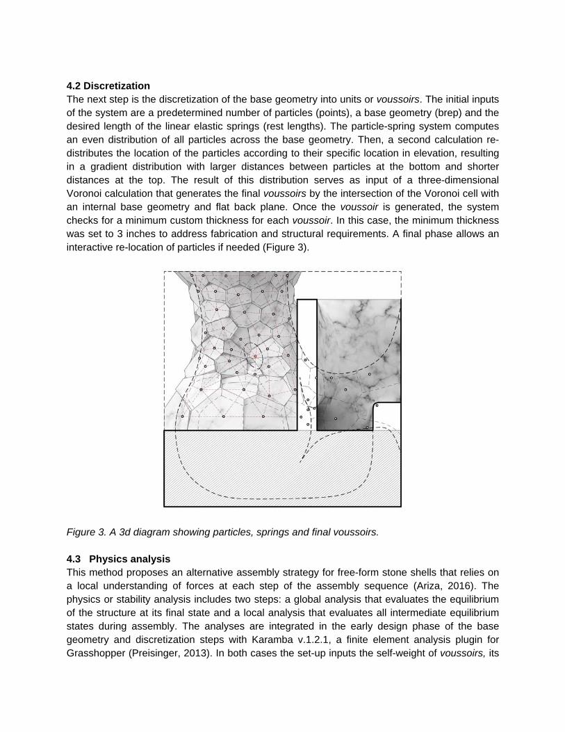
positioning error is to utilize an external synchronous positioning axis (rotary table). By allowing the robot pose to be restricted to a smaller range of motion and reduced range of joint configurations, accuracy can be improved; in addition, the overall work volume of the robot is increased significantly. Both of these techniques were employed in the fabrication of the prototype. In order to maximize part accuracy, individual voussoirs are processed from a solid blank to finished part using a single fixturing setup on a flat back face. This avoids the difficulty of re-registering a completely non uniform geometry which has been partially machined and then repositioned. 4.5.2 Cutting operations In the production of the individual voussoirs four separate carving operations are utilized. The majority of the stock removal is accomplished with the use of a 840 mm diameter x 8 mm thick diamond composite blade. The flat bearing surface of the voussoirs is accomplished with a single traversing (zig-zag) operation which allows for a maximum amount of material removal with a minimum amount of machining time as only the material within the kerf of the blade is removed (Figure 8a). The roughing operation for the internal face is performed using a parallel kerf cutting operation which removes stock more rapidly than comparable milling operations due to the utilization of a step-over that is greater than the width of the tool (Figure 8b). Material not removed in the kerfing passes generally falls off due to blade vibration or is removed by hand. A step-over greater than the width of the tool also ensures even wear of the cutting surface. The finishing passes on the internal face of the voussoirs is a side cutting operation performed in a motion perpendicular to the previous direction of the blade. Finally, the joint voids are milled with an electroplated diamond tool using pocketing operations (Figure 8c).
Figure 8. Cutting operations: (a) edge saw cutting, (b) face side cutting, and (c) detail milling.
4.5.3 Automation of geometry for toolpathing While the implemented algorithmic design approach generates highly unique geometries with relative ease, it was important to identify production bottlenecks early in the project. While fully automated design to machine code strategies have been implemented in certain projects, it was determined that a hybrid approach would integrate better with the fabrication workflow at Quarra Stone. This involved the automated generation and organization of 3d part files with the needed “helper” geometry to work smoothly with the production CAM package in use by the fabrication team. 4.6 Assembly Several challenges arise in the placement of the individual voussoirs. First, the stones are never set upon a level surface, and the center of mass of the piece is often not directly over the bearing surface resulting in temporary instability during assembly. Though the meeting surfaces of the stones are drafted in all directions, facilitating placement and allowing for a transfer of compressive forces between the voussoirs once assembled, there are still several degrees of freedom in the movement of the stones as they are individually placed. To counteract this temporary instability a two-step assembly method was implemented as described in section 4.4.3. 4.6.1 Fitting and registration In the first step, using minimal, adjustable tension and compression falsework, each voussoir is fit in place by hand, and registered to its correct location by a pre-cast drift-pin which is tapered on all surfaces to apply tension normal to the adjacent faces of the two stones. This registering operation facilitates the minute adjustment of the voussoirs after placement and serves to hold them in place temporarily during the completion of the entire ring. The malleable drift-pins also have the capacity to be adjusted to fit in case of fabrication inaccuracies. 4.6.2 Casting and fixing In the second step after the placement of an entire ring of voussoirs, the pre-machined drafted voids of the shear details located between the most vertical faces of the stones are filled with metal in-situ, permanently fixing the ring together. Finally, the pre-cast adjustable pins holding the course in place are cast over in-situ, permanently locking the drift-pin in place. Additionally, any gaps between voussoirs which result from the tolerances in fabrication are filled during the pouring of the in-situ joints. This has been a typical use of lead in ancient stone construction. If accumulation of error produces extremely large gaps between units, the edge geometry can be adjusted informed by an in-situ assessment of the location of individual voussoirs using digital scanning methods. This series of operations is then repeated for each consecutive ring. 5. Research Evaluation The validity of the structural analysis and assembly method was assessed through a series of material tests and mock-ups. The former evaluated the material strength and efficiency of the joint geometry throughout a series of controlled specimens. Different mock-ups explored the possibilities and performance of the various available machining methods, casting and

assembly processes, and materials to be used in the pre-cast and in-situ details. A final 6-piece mock-up served as a final evaluation of the overall detailing and assembly method. 5.1 Material tests Strength tests were performed on two different casting alloys: pewter (A3 or Brittania), an alloy of tin, copper, and antimony; and zamak 3, an industrial die-casting alloy of majorly zinc, copper, magnesium. Despite having a much lower ultimate yield strength (7.65 kips) than zamak (35 kips), pewter was selected due to his lower melting point, shrinkage, and brittleness, its resistance to work hardening, and higher flow rate (Figure 9). Ten geometric variations of tension joints were tested. Controlling variables included the length (120-160 mm), depth (30-50 mm) and thickness (11-16 mm) of the joint (Figure 10a). Three specimens of each geometry were tensioned using a hydraulic ram. The most successful specimens (E, C and D, F) failed between 2000 and 2800 lb (Figure 10b).
Figure 9. (a) Casting of specimens, (b) casting of joints in-situ, and (c) sample specimen of tension joint.

Figure 10. Geometric variations of joints (from upper left: A to J) and tension testing of specimen F1. 5.2 6-Piece Mock-up A 6-piece mock-up made from Vermont Marble served to evaluate the various aspects of the research. In regard to the fabrication results, inaccuracies (up to 3 mm) related to the location of joints were handled with the specific assembly strategies described in section 4.6. The most critical inaccuracy location was found to be the intrados of the voussoir, for which further fabrication and assembly strategies need to be studied. In regard to the assembly method, ratchet straps attached to the fixtures of the flat back face were found to be a useful temporary falsework method to support pieces in place until the final fixing of the ring is achieved. Regarding the structural performance, units with larger instability were successfully supported by drift-pins in cases of no larger than 3mm inaccuracies. This last test proved the importance of the geometry of the drift-pin as a tolerance handling method.

Figure 11. 6-piece mock-up, exterior.
Figure 12. 6-piece mock-up, interior.

Figure 13. 6-piece mock-up, detail showing unit 3 and 5 locked with the in-situ casting technique, and unit 6 supported by 2 drift-pins. 6. Conclusion This research successfully demonstrates a proof-of-concept to design, develop, analyse, and construct complex geometry shell structures, which satisfy a confluence of architectural concerns, without the need for extensive falsework, formwork, or templating. Through computation, digital fabrication, and the adaptation of ancient detailing strategies, this method points to a possible application of design in synchronous feedback with the constraints of assembly. While the potentials of such a method accomodate an endless number of possible geometries, the analysis points to a series of constraints. These constraints exist primarily in the structural and material properties of stone and metal, the geometric constraints of fabrication, as well as the problematics of compounding errors during assembly. Future research seeks to further evaluate the capabilities of assembly simulation and sequential fixing in the construction of a full scale marble caldarium.

Figure 14. Caldarium (a) exterior, and (b), (c) interior views. References
Ariza, I., 2016. Decoding Details: Integrating Physics of Assembly in Discrete Element Structures, Master's thesis, Massachusetts Institute of Technology.
Clifford, B. and McGee, W., 2015. Digital Inca: An Assembly Method for Free-Form Geometries. In Modelling Behaviour (pp. 173-186). Springer International Publishing.
Clifford, B. and McGee, W., 2014. La Voûte de LeFevre: a variable-volume compression-only vault. eds) Gramazio, F, Kohler, M, and Langenberg, S Fabricate Negotiating Design and Making, Verlag.
Deuss, M., Panozzo, D., Whiting, E., Liu, Y., Block, P., Sorkine-Hornung, O. and Pauly, M., 2014. Assembling self-supporting structures. ACM Transactions on Graphics (TOG), 33(6), p.214.
Kaczynski, M.P., McGee, W. and Pigram, D.A., 2011. Robotically Fabricated Thin-shell Vaulting: A methodology for the integration of multi-axis fabrication processes with algorithmic form-finding techniques. ACADIA 2011. Leroy, S., Hendrickson, M., Delqué-Kolic, E., Vega, E. and Dillmann, P., 2015. First Direct Dating for the Construction and Modification of the Baphuon Temple Mountain in Angkor, Cambodia. PloS one, 10(11), p.e0141052. Lachauer, L., Rippmann, M. and Block, P., 2010. Form Finding to Fabrication: A digital design process for masonry vaults. In Proceedings of the International Association for Shell and Spatial Structures (IASS) Symposium. Meisenheimer, W 1984, 'Von den Hohlräumen in der Shale des Baukörpers = Of the hollow spaces in the skin of the architectural body', Daidalos, 13, pp. 103-111, Avery Index to Architectural Periodicals.

Piker, D., 2013. Kangaroo: form finding with computational physics. Architectural Design, 83(2), pp.136-137.
Preisinger, C., 2013. Linking structure and parametric geometry.Architectural Design, 83(2), pp.110-113.
Protzen, J.P. and Batson, R., 1993. Inca architecture and construction at Ollantaytambo. Oxford University Press, USA.
Rippmann, M. and Block, P., 2011. Digital Stereotomy: Voussoir geometry for freeform masonry-like vaults informed by structural and fabrication constraints. In Proceedings of the IABSE-IASS Symposium.
Rippmann M., Van Mele T., Popescu M., Augustynowicz E., Méndez Echenagucia T., Calvo Barentin C., Frick U. and Block P., 2016. The Armadillo Vault: Computational design and digital fabrication of a freeform stone shell, Advances in Architectural Geometry 2016,: pp. 344-363.
ACKNOWLEDGEMENTS This research was conducted as part of the 2016 QuarraMatter Fellowship, an industry/academy partnership between Quarra Stone (www.quarrastone.com) and Matter Design (www.matterdesignstudio.com). Each summer, two fellows are embedded in Quarra Stone to produce a research project in advanced fabrication techniques. The form generation employs T-Splines (www.tsplines.com) as an organic modeler to inform Grasshopper (www.grasshopper3d.com), a plugin developed by David Rutten for Rhinoceros (www.rhino3d.com), a program developed by Robert McNeil. In addition, the analysis computation employs Karamba (www.karamba3d.com), by Clemens Preisinger, Kangaroo (www.grasshopper3d.com/group/kangaroo), Plankton (Ibid./plankton) and MeshMachine (Ibid./meshmachine) by Daniel Piker. The fabrication computation utilizes a custom c# script by Wes McGee to automate toolpath geometries, SUM3D (cap-us.com) for toolpath generation, and ROBOmove (www.qdrobotics.com/eng/robomove), by QD Robotics for robot program simulation. Structural testing provided by Daren Kneezel and Jeff Scarpelli of Wiss, Janney, and Elstner (www.wje.com). Project team includes Brian Smith, Alireza Seyedahmadian, and Alexander Marshall.


![FrameFab: Robotic Fabrication of Frame Shapesweb.mit.edu/yijiangh/www/papers/a224-huang.pdf · Protopiper [Agrawal et al. 2015], a computeraidedhand-heldfabricationdevice,isintroducedtoallow](https://static.fdocuments.in/doc/165x107/5f55dddba543f63ada60e5a9/framefab-robotic-fabrication-of-frame-protopiper-agrawal-et-al-2015-a-computeraidedhand-heldfabricationdeviceisintroducedtoallow.jpg)