RoboCup Soccer SSL - WordPress.com · STEVENS INSTITUTE OF TECHNOLOGY RoboCup Soccer SSL Platform...
110
STEVENS INSTITUTE OF TECHNOLOGY RoboCup Soccer SSL Platform Design Phase VI Final Report “I pledge my honor that I have abided by the Stevens Honor System.” May 3, 2010 Patrick Alfonzo ________________________________________ Andrew Domicolo ________________________________________ Michael Fatovic ________________________________________ Amanda Goldman ________________________________________ Daniel Silva ________________________________________
Transcript of RoboCup Soccer SSL - WordPress.com · STEVENS INSTITUTE OF TECHNOLOGY RoboCup Soccer SSL Platform...

STEVENS INSTITUTE OF TECHNOLOGY
RoboCup Soccer SSL Platform Design Phase VI Final Report
“I pledge my honor that I have abided by the Stevens Honor System.” May 3, 2010
Patrick Alfonzo ________________________________________
Andrew Domicolo ________________________________________
Michael Fatovic ________________________________________
Amanda Goldman ________________________________________
Daniel Silva ________________________________________

2
Executive Summary
This is the final report for the Stevens Institute of Technology’s Mechanical Engineering
Department’s RoboCup Soccer Small Size League (SSL) Platform Design Senior Design project.
Based around the RoboCup Soccer SSL International Competition, the team took on the
challenge to make a set of completely autonomous robots who participate in a soccer match.
Divvied up into a total of six phases, the Stevens Mechanical Engineering Senior Design
curriculum focused on the main constituents of any design process—research and planning,
technical analyses, finalizing designs, manufacturing and fabrication, subsystem testing and
debugging, final testing and presentation.
Over the past school year the RoboCup design team has completely utilized each phase to
further the development of its project. In Phase I the team chose the RoboCup Soccer SSL as its
project, did the proper research of the competition, designed the overall system network for the
project as a whole, and selected the essential components necessary to construct a robot. The
team further advanced its project in Phase II by performing pertinent technical analyses to
determine whether or not the team’s initial plans were physically possible. Phase III helped the
team develop original design specifications which were then manufactured both by the team and
by the Stevens Institute of Technology’s Machine Shop as well as purchasing the final listing of
necessary components. In Phase IV the design team fabricated the initial prototype and tested
preliminary subsystems. Phase V the team concentrated its efforts on finalizing the prototype,
programming the fundamental software modules, and performing a series of final tests. In this
final stage, Phase VI, the team has continued its finalization of the robot prototype as well as
producing several various presentations and demonstrations including Senior Design Expo, the
Technical Communications Competition, and the Research and Entrepreneurship Day.
This report is the compilation of the Stevens RoboCup Senior Design Team’s yearlong
effort towards the production of a RoboCup Soccer SSL prototype. The information presented
here shows the advancement and growth of the design team as a whole while the project itself
progressed.

3
Table of Contents
Executive Summary …………………………………………………………………………… 2
Introduction …………………………………………………………………………………… 5
Project Objectives …………………………………………………………………………… 6
System Design
Process Flowchart …………………………………………………………………… 7
Component Selection
Motor Selection …………………………………………………………………… 9
Wheel Selection …………………………………………………………………… 9
Visualization ………………………………………………………………….. 10
Wireless Communication ………………………………………………………….. 11
Motor Control ………………………………………………………………….. 11
Kicker and Dribbler Assembly ………………………………………………….. 11
Body and Chassis ………………………………………………………………...... 12
Preliminary Design Specifications ………………………………………………….. 13
Budget Estimate ………………………………………………………………….. 20
Technical Analysis
Directional Control ………………………………………………………………….. 21
Vision Recognition ………………………………………………………………….. 22
Power Consumption ………………………………………………………………….. 23
Driven Kick late ………………………………………………………………….. 23
Prototype Manufacturing and Assembly
Purchasing ………………………………………………………………………….. 25
In-house Manufacturing ………………………………………………………….. 26
Out-of-house Manufacturing
Wheel Adapters ………………………………………………………………….. 26
Dribbler Mechanism ………………………………………………………….. 28
Kicker Assembly ………………………………………………………………….. 29
Final Design Specifications ………………………………………………………….. 30
Subsystem Testing
Motor Speed ………………………………………………………………………….. 31
Dribbler Mechanism ………………………………………………………………….. 35
Motor Mount Assembly ………………………………………………………….. 37
Software Development
Strategic Loops ………………………………………………………………….. 38
Final Program ………………………………………………………………………...... 38
Challenges Encountered
Laboratory Size Constraint ………………………………………………………….. 41

4
Electronics and Communications Incompatibilities ………………………………….. 41
Future Plans ………………………………………………………………………………….. 42
Senior Design Experience ………………………………………………………………….. 43
Changes to Design ………………………………………………………………………….. 43
Conclusion ………………………………………………………………………………….. 44
Gantt Chart ………………………………………………………………………... Appendix A
Purchased Parts List ………………………………………………………………... Appendix B
Preliminary Budget ……………………………………………………………….. Appendix C
Finalized Budget ……………………………………………………………….. Appendix D
Nugget Charts (Phase I – VI) ……………………………………………….. Appendix E
Machine Shop Designs ……………………………………………………….. Appendix F
Selected Component Datasheets ………………………………………………... Appendix G
RoboCup SSL 2010 Rules and Regulations ………………………………... Appendix H

5
Introduction
The Stevens RoboCup Design Team has made significant progressions throughout this
past year. The team took on the immense challenge to design, create, and establish the first ever
Steven Institute of Technology RoboCup team. The initial objective of the team was to model,
manufacture, and program a complete set of autonomous robots capable of competing in the
RoboCup Soccer World Cup. With prominent obstacles from the beginning the team was able to
refocus its primary objective to create a working prototype of a singular RoboCup robot. The
working prototype RoboCup robot would need to be able to navigate around a test field,
determine its location and that of the ball in play, retain possession of the ball, and kick the ball
just as a real soccer play would. Through a strong concentrated effort from all team members
throughout the six design phases, the team’s project propelled forward and set itself aside from
the rest of the Senior Design groups.
After a long year of planning, designing, purchasing, manufacturing, fabricating,
programming, debugging, and testing the design team is ready to present its entire process from
start to finish with an end result with which all members are pleased with. The team has seen
many revisions of its original design concepts as seen in Phase I; however, its overall system
design stayed the same.
In the previous semester, the group relied on research and development to analyze the
Official RoboCup Competition Rules and Regulations located in Appendix H and select a set of
components to construct the robot from. The Stevens team then conducted several technical
analyses which helped foster an understanding of the more complex features of the project as a
whole as well as determine whether or not some of the team’s design plans were physically
plausible. The team then proceeded to solidify its design plans of the parts of the robot which
were to be fabricated, both by the team and by the Stevens Machine Shop. The engineers also
purchased, ordered, and received all necessary components to complete its one fully operational
robotic soccer player. A complete listing of the team’s purchased components can be seen
attached in Appendix B.
The team continued its diligent work this semester by successfully tackling Phases IV
and V in the same manner that it approached Phases I-III. Once the team received all of its

6
purchased components, the engineers started with compatibility and subsystem testing. The
project throughout this past semester was separated into two separate yet equal factions—
hardware/prototype assembly and electronics/programming/communications operation. The
team set up a test field used to optimize the vision recognition software as well as perform
various subsystem tests such as motor speed and dribbler/kicker assembly operation. After the
each of the subsystem tests proved sufficient, the team assembled the entirety of the prototype.
The design team was then able to focus on perfecting the LabVIEW program necessary to
complete its primary objectives of traversing around the playing field, finding the ball, retaining
possession of the ball, and kicking the ball.
Lastly, during this last phase the team presented its prototype and overall design work in
various demonstrations. The first was the Senior Design Expo in which all Senior Design groups
of every major convened in the Canavan Arena in the Charles V. Schaefer, Jr. Athletic and
Recreation Center on April 28, 2010. The team set up its test field and displayed the prototypes
mechanical maneuverability via a manual control system. The reason behind this manual control
was that the LabVIEW programming was not calibrated to the Design Expo’s surroundings and
the dimensions and tolerances built into the system were no longer applicable. The team also
presented their project to a non-technical audience in the Technical Communications
Competition held by the Stevens Office of Communication Professionals. At this competition
the team had to present its overall project in a non-technical manner, emphasizing on
presentation skills and delivery. The Stevens RoboCup Design Team took first place at this
competition. Finally, the team was also requested to attend the Stevens Research and
Entrepreneurship Day in which the team presented its overall project to a panel of various
potential investors, professors, and business professionals.
Project Objectives
The Stevens RoboCup Design Team had many objectives which needed to be completed
this past semester for their project to be successful. As previously stated, the group’s primary
object was to completely construct a working prototype of a singular RoboCup robot. Once the
fabrication of the robot was completed, the team could assess the task of troubleshooting the

7
communications between the robot and the host computer. As soon as the robot and the central
computer could communicate effectively, the group could then focus the center of its attention in
amending and correcting the LabVIEW program which controls the movements of the robot
around the playing field. In order to test the program and resultant movements of the robot
accurately, the team constructed a test field in the Stevens Robotics and Controls Laboratory in
Room 301 in the Edwin A. Stevens Building. This field was constructed from a green outdoor
carpet and white athletic tape to ¾ scale of the dimensions provided by the RoboCup 2010 SSL
Regulatory Committee.
System Design
This section pertains to most of the fundamental designs and organizational attributes
found in Phase I. Topics covered in this section include the process flowchart, component
selection, preliminary designs, and budget estimates. These issues helped the design team plan
out its project accordingly and make the necessary initial steps towards a working prototype.
Process Flowchart
The first necessary task that the team needed to develop was a complete flowchart in
which how the team spells out how its entire system will work. The team’s entire process
focuses around the globalization camera which is located above the field. The camera watches
the entire field and can track all players on the field as well as the ball in play. The camera’s
image is processed on the main processing computer through a LabVIEW image recognition
program. This program can track the location of the ball and the robot as well as its current
angle of rotation. Using this information and specific algorithms coded into the program
LabVIEW can communicate wirelessly through the XBee Module via the USB Hub. This
broadcasts the commands to the receiving XBee Module located on the robot. The onboard
XBee chip then communicates to the PIC and custom circuitry on the robot via a serial adapter.
These electronics then delegate the proper commands to the appropriate Drive Motors, Dribbler
Motors, and Solenoid Valve. While this functional loop is running, the camera is still capturing
the physical actions of the robot and sending the information back to the host computer. This

8
capture feed then acts as a feedback control in order to make the necessary changes to fine-tune
its strategic commands. This process is presented graphically in Figure 1 below.
Figure 1: The Stevens RoboCup Design Team's Process Flowchart
Component Selection
This section briefly retouches upon the various components selected for the RoboCup
prototype. In each section a short comparison of other possible choices is presented and the
specific reasoning behind the chosen component. For more specific information on any of the
chosen components the supplied datasheet has been attached in Appendix G.

9
Motor Selection
The following chart illustrates several motors that were considered for the RoboCup application
Motor Price/Unit Size Speed Peak Torque Peak Current
Anaheim Automation BLWR17 Brushless
DC Motor $50
1.18" long
1.65" diam. 5000 rpm 8.5 oz/in -
Premotec BL48 EB Brushless DC Motor
- 3.7cm long
5.4cm diam. 4600 rpm 43 mNm 2.13 A
Maxon EC45 Flat Brushless DC Motor
$60 1.6cm long
4.3cm diam. 4400 rpm 260 mNm 2.30 A
LynxMotion GHM01 DC Motor
$22 4.8cm long
3.7cm diam. 200 rpm - 2.30 A
Each of these motors was provided with a datasheet which listed all of the important
specifications. The group weighed each of the motors designs against one another and ultimately
went with the model that best fit the project’s needs and fit within the budgetary constraint. The
group decided to go with the LynxMotion GHM01 DC motor (highlighted) for its final design.
This motor selection has been highlighted in highlighted in yellow in the chart above.
Wheel Selection
The team decided early in the project’s life that something different than a conventional 4
wheel design will be needed. The robot will need to have maximum motor control flexibility
and will need to allow the robot to move easily in two dimensions—to both rotate and translate
in place. The design engineers agreed that an omniwheel design meets all of their requirements.
The following chart shows a compiled list of particular omniwheel designs that have been used
by RoboCup teams of the past as well as several new models.

10
Name Price Diameter Max Load Image
AcroName R76 $12.75 4cm diam. 15 lbs
AcroName R129 $26.25 6cm diam. 50 lbs
Vex OmniWheel $19.99 7cm diam. -
The AcroName R76 omniwheel was selected because it was the most cost efficient solution that
met all of the project’s design requirements.
Visualization
The Stevens RoboCup Design team determined in Phase I that during game play a global
position camera would be utilized to collect real time data. This visual data will be sent to a
central PC and processed using LabVIEW. The camera that was selected needed to be a high
quality color camera, compatible with LabVIEW’s
built in imaging software, and have a high enough
frame refresh rate that it would be able to keep up
with the high speed game. The team settled on the
Prosilica GC750C Color Camera. The camera,
shown in Figure 2, meets all of the team’s
requirements.
Figure 2: Prosilica EC750C

11
Wireless Communication
The main processing computer will need a way to communicate
wirelessly with the robotics player on the field. The team came up
with several solutions that could have been used to effectively
transmit data and commands to the robots, such as Bluetooth and
WiFi technologies. However, the optimal solution the team
selected was the ZigBee Wireless Communication Protocol. This
component provides the Stevens RoboCup team the required ease
of wireless communication, speed of data transmission, all the while staying within budget
constraints. Of the various ZigBee units available, the team had decided to purchase the XBee
Module, shown in Figure 3, for not only its size but its efficiency. This chip uses a serial
communication protocol that is fully compatible with LabVIEW and will also provide the
necessary high-speed data transfer.
Motor Control
The group investigated several options for motor control and on-board data processing
boards. The most cost-efficient solution the team could develop was to use the PIC Interface
Boards that were provided in the Stevens Institute of Technology’s Engineering Design 1 and 2
Program. These PIC Boards have adequate processing capabilities as well as sufficient number
of I/O channels to operate the robot’s on-board motors and solenoid. These PIC boards are also
compatible with the ZigBee Wireless Communication Protocol and the specific XBee Module
that has been selected.
Kicker and Dribbler Assembly
The design team furthered their research by investigating and evaluating the effectiveness
of previous winning school’s Kicker and Dribbler Assembly mechanisms. The Stevens
RoboCup team decided to select a simple DC motor for the dribbler mechanism (to keep the
player in contact with the game ball) and an electric solenoid for the kicker mechanism (to shoot
the ball during game play). The Dribbler motor selection considerations are displayed in the
following chart.
Figure 3: XBee Module

12
Motor Price Size Speed Pros Cons
MicroMo 2230F006S $35.00 1.75" long
0.85" diam. 8,000 rpm
-High speeds
-Small -Expensive
MicroMo 1331T006SR $40.00 1.75" long
0.50" diam. 12,000 rpm
-High speeds
-Small -Expensive
Lynxmotion Gear Head Motor - 7.2vdc
30:1 $22.00
1.75" long
1.5" diam. 291 rpm
-Inexpensive
-Small -Low speed
The team decided to use the LynxMotion Gear Head Motor (highlighted yellow) because it met
the speed requirements as well as being the most inexpensive solution.
The considerations for the electric solenoid are shown in the following chart. The team’s
selection has been highlighted in yellow.
Solenoid Price Size Power Pros Cons
Bimba 0071
Pneumatic solenoid $12.00 2" long
17.5 psi (78N)
-Relatively inexpensive -Complex air system
Solenoidcity S-20-100-H electric
solenoid $45 2" long
125 oz-f
(34.75N) -Easy installation
-Less force than pneumatic
-Expensive
Body and Chassis
After research material options and discussing manufacturability with Stevens Institute of
Technology’s Machine Shop staff, it was determined that the first prototype robot would be
constructed out of an acrylic plastic material. This is a low cost solution that will provide
durability, flexibility, as well as ease of machining. Eventually, an entire team of robots may be
fabricated using aluminum components to increase strength and stability of the chassis.

13
Preliminary Design Specifications
Let it be known that the designs represented in this section are the initial models of what the
Stevens RoboCup Design Team intended to manufacture and fabricate. For the final design
assembly please go to the Prototype Manufacturing and Assembly Section. Thank you.
Throughout the Stevens RoboCup Design Team’s beginning stages, the design team
concentrated its efforts to come up with several design considerations for its prototype model.
When the design engineers were creating a three dimensional model of the chassis and body of
the robot, it was required to take the components and electronics into consideration. These
elements included the motors, solenoid, and wheels attached to the chassis and the IC boards
within the confines of the outer casing of the robot. The image in Figure 4 shows the
specifications of the motor, LynxMotion GHM-01, the team had selected to move the wheels.
Figure 5 shows the recommended mounting brackets that will be used to attach the motors to the
chassis.
Figure 4: Specifications of the LynxMotion GHM-01Motor
Source: http://www.lynxmotion.com/images/data/ghm01.pdf

14
Figure 5: Specifications for the LynxMotion GHM-01 Mounting Bracket
Source: http://www.lynxmotion.com/images/data/mmt-02.pdf
The last purchased material that is included in the operations of the robot was the solenoid valve
which triggers the movement of the kicker plate and subsequently strikes the ball. Figure 6
shows a section of the provided specification sheet of the chosen solenoid, the Solenoid City S-
20-100-H Electric Solenoid.
Figure 6: Specification of the Solenoid City S-20-100-H Electric Solenoid
Source: http://www.solenoidcity.com/solenoid/tubular/s-20-100hp1.htm

15
The following images, Figures 7 – 11, are the components the design team had originally
decided to be manufactured at the Stevens Institute of Technology’s Machine Shop. As it has
been mentioned before, these preliminary design components will be first machined out of
aluminum for the prototype design stages.
a. Kicker Plate – attached to the solenoid valve, strikes the ball
Figure 72: Stevens RoboCup Design Team’s Kicker Plate Design
b. Dribbler – creates a backspin on the ball which allows the robot to keep position whilst moving
Figure 8: Stevens RoboCup Design Team’s Dribbler Design

16
c. Dribbler Brackets – supports and affixes the dribbler mechanism to the chassis
Figure 9: Stevens RoboCup Design Team’s Dribbler Bracket Design
d. Solenoid Brackets – stabilizes and secures the solenoid on the chassis
Figure 30: Stevens RoboCup Design Team’s Solenoid Shaft Bracket Design
Figure 11: Stevens RoboCup Design Team’s Solenoid Rear Bracket Design

17
The Stevens RoboCup Design Team then completed its initial design for the robot
prototype. Using the previous modeled components to be manufactured the team was able to
design a three dimensional view of the layout of the robot. The following images, Figures 12 –
17, are multiple views of the preliminary assembled design of the chassis complete with to scale
components. All of the components that are colored red are the separate purchased items
(motors, motor brackets, wheels, and solenoid). The elements which are blue and transparent
grey are the parts which the design team will be fabricating in the Stevens Institute of
Technology’s Machine Shop (solenoid brackets, kicker plate, dribbler, dribbler brackets, and
chassis). The orange sphere in the images represents the golf ball which will be functioning as
the soccer ball during the competition. The height of the prototyped chassis, including the
wheels is 4.24 inches, which leaves the team with an extra 1.67 inches available for on board
electronics and circuitry.
Figure 124: Top View of the Stevens Preliminary Assembled Prototype Design

18
Figure 13: Front View of the Stevens Preliminary Assembled Prototype Design
Figure 14: Right View of the Stevens Preliminary Assembled Prototype Design

19
Figure 15: Isometric View of the Stevens Preliminary Assembled Prototype Design
The kicker device will strike the ball away from the robot by a force which is provided by
the electric solenoid system. In Figure 16, the solenoid, in red, is attached with the brackets, in
blue. The kicker, the L-shaped device, is attached to the solenoid shaft and stopped by a washer
at the end of the shaft before coming in contact with the dribbler mechanism.
Figure 16: Stevens RoboCup Design Team’s Kicker Device

20
The dribbling mechanism, shown in Figure 17, is a simple mechanism made of a motor, modeled
in red, and a simple roller shown in blue. The two elements are connected by a belt, which will
be used to harness the rotation of the motor and transfer that to the dribbler. The dribbler is
attached to the chassis by two L-brackets. The belt is driven by the motor in a counter clockwise
direction—this will in turn keep the ball in contact with the robot whenever it has possession,
until the ball is kicked by the kicker device.
Figure 5: Stevens RoboCup Design Team’s Dribbling Device
Budget Estimate
Prior to purchasing all of the essential components for the team’s prototype, the group
created a detailed itemized budget. The preliminary budget, which can be found attached in
Appendix C, contains documented retail prices and references for each component. The total
amount cost to completely purchase, manufacture, and fabricate an entire team of RoboCup
robots would be $2,207.58. The budget continues to show that the cost of just one complete
robot is $285.44, which does not include the cost of the camera, and other miscellaneous
materials (such as the practice field, practice game balls, etc.). This budget had been reviewed
by the Director of the Stevens Mechanical Engineering Department and has preliminarily been
approved. The RoboCup Design team had agreed to continue with their intent to purchase
enough materials to fabricate one working prototype, then after a successful proof of concept the
group will then continue with the fabrication of the remainder of the team time providing.

21
Technical Analysis
This section of the Stevens RoboCup Design Team report reflects the work accomplished
in Phase II by the group. These studies included Directional Control Analysis, Vision
Recognition Analysis, Power Consumption Analysis, and Driven Kick Plate Analysis.
Directional Control
The team presented the benefits of using a three wheel omniwheel drive train as opposed
to a traditional four wheel Akerman Steering drive system. As it can be seen in Figure 18 below,
the omniwheel system allows for motion in both the x and y direction simultaneous, whilst the
Akerman system only allows motion in the direction the front wheels are pointing.
Figure 18: Traditional Akerman Steering Drive System vs. Omniwheel System
Source: http://www.societyofrobots.com/robot_omni_wheel.shtml
As it had been discussed in the Phase I proposal, the Steven RoboCup Design Team
decided that the best solution for a wheel orientation and configuration would be a three
omniwheel system. Although this helped reduce costs, the team is now required to design a
much more complex motion control system. The second phase of the drive and directional
control analysis calculated the power ratios which would be required to travel in any given
direction. In theory, these ratios provide a vector calculation that would be required to complete
in order to command the robot to travel in any direction. In order to increase response time, the
team could place these ratios in a look up table which could later be utilized to quickly obtain the
proper command for any specific direction.

22
Vision Recognition
The vision recognition analysis presented the process which will be utilized by the group
to track the location and orientation of the team’s robotic player as well as the ball in play. The
process uses LabVIEW’s image processing to precisely locate and match a designated test image
to that in the real-time image taken by the overhead global visualization camera. This image
matching can be seen in Figure 19.
Figure 19: Vision Recognition Analysis
As the LabVIEW image shows, the image processing unit can differentiate colors and
degrees of rotation and translation even when there are competing colors viewed. In Figure 20
the LabVIEW software’s output is shown which shows the change in position, angle, and scale.
It also tells the users how confident LabVIEW is in its image processing that it has located the
test image in the area called ―Score‖.
Figure 20: LabVIEW's image processing output

23
Power Consumption
After selecting the majority of the components needed to assemble a robot, the Stevens
RoboCup Design Team needed to ensure that it had a battery capable of running every process
simultaneously. A power consumption analysis helped determine the size of the battery required
to run all of the electrical systems on board of the robot. Taking into consideration the length of
the soccer match (20 minutes) and the power consumed the by the drive motors, dribbler motor,
and solenoid, the group determined that a 2000mAh battery was required. Ultimately, the team
decided to purchase a 12V, 2000mAh Nickel Metal Hydride battery (NiMH). This battery and
its charger can be seen in Figure 21.
Figure 21: 12V, 2000mAh NiMH Battery and its charger
Driven Kick Plate
The Stevens RoboCup Design Team wanted to devise a new way to elude the defending
team’s robot. Some teams have been known to have one designated player with an angle kicker
plate used to chip the game ball over the field. During the Phase II analyses, the group decided
to investigate to automate this angled kick plate so that not only could every robot have the
ability to chip the ball, but also so the height and the distance the ball is chipped can be adjusted
in each situation. This would surely set the Stevens team aside from the rest.
There are a particular set of constants that can be assumed to be universal throughout the
RoboCup Competition teams. The maximum height (150 mm) and maximum diameter (180
mm) for each competing robot have been assumed. Using this information, along with the real-
time measured center to center distance from the offensive to the defensive players (made

24
available by the global visualization camera and LabVIEW), the team can program the computer
to calculate the correct angle and initial velocity to clear the opposing player. To calculate the
correct angle, the dimensions were input into projectile motion equations. The angle was the
determined using an Excel spreadsheet which outputs the necessary angle and initial velocity,
both of which can be sent as commands for the robot to carry out. The physics mechanics
behind this theory can be seen in Figure 22. An example of the Excel spreadsheet follows after
the picture. The yellow row represents the real time measured data, the green row represents a
pre-game determined variable which designates the percentage of the height which the ball will
clear the defender, and the red row represents the output required angle of attack.
Figure 22: Driven Kick Plate Analysis

25
Center to Center Distance: 0.305 m = 1.001 ft
Distance to Defender: 0.125 m = 0.41 ft
Buffer Zone (Leading Edge): 25%
Distance to top of curve: 0.1875 m = 0.615 ft
Time to top of curve: 0.081 s
Gravitational Acceleration: 9.8067 m/s² = 32.17 ft/s²
Initial Velocity (y-axis): 1.9177 m/s = 6.292 ft/s
Initial Velocity (x-axis): 1.5432 m/s = 5.063 ft/s
Initial Velocity (magnitude): 2.4615 m/s = 8.076 ft/s
Angle of Attack: 0.8932 ° = 0.016 rad
Prototype Manufacturing and Assembly
This section of the Stevens RoboCup Design Team’s report deals primarily with the work
completed in the spring semester. These actions include, but are not limited to, purchasing, in-
house manufacturing, out-of-house manufacturing, final design specifications, and assembly.
Purchasing
At the beginning of the spring semester the team had already put in the appropriate paper
work to order the approved components that were selected and solidified over the previous
semester. After a conversation with the Director of the Stevens Mechanical Engineering
Department regarding a budget extension, the group was allowed to purchase enough material to
make one prototype model, as previously discussed. The group scaled back its original
quantities desired and developed a finalized budget which accurately depicts the team’s
expenditures over the school year. The purchased components can be seen in the Parts List in
Appendix B and the final itemized budget list can be seen in Appendix D.

26
In-house Manufacturing
Although technically all of the RoboCup Design Team’s manufacturing was done ―in-
house‖ in terms of being completed at Stevens, there were a few components that were made by
the team itself.
The entire chassis structure was designed and cut by the team utilizing the laser cutter
made available in the Robotics and Control Laboratory, in which the team did all of its testing
and fabrication. The main chassis base plate was designed to allow the drive motors to be
mounted 180° apart and equidistant from the edges of the circle. The front face of the circle was
cut out in an attempt to comply with the RoboCup Rules and Regulations regarding covering the
ball in play. The base plate also needed to have a clearance hole which allowed the kicker
plate’s extension arm to travel without disrupting the dribbler mechanism which was located in
its own clearance hole in the front of the chassis. The chassis was designed to be modular in the
sense that with the addition of standoffs various tiers could be stacks on top of one another
allowing numerous layers to be created for electronics and other onboard components.
A three dimensional view of these pieces can be seen in the Final Designs Specifications
section of this report. The parts that are shown clear and/or gray are the chassis tiers that were
manufacture in-house.
Out-of-house Manufacturing
The components discussed in this section that have been referred to manufactured ―out-
of-house‖ are parts that have been designed by the team yet created by the Stevens Machine
Shop. The majority of these designed parts’ drawings have been included in Appendix F.
Wheel Adapters
An issue that arouse for the design team after the purchased items arrived was that the
omniwheels did not come equipped with a way to affix them to the drive motor shafts. After
researching various options and conferring with the Stevens Machine Shop Staff the best fix for
this problem was to manufacture a set screw adapter that is press fit onto the wheel itself. This
press fit adapter can be seen in Figure 23 below.

27
Figure 23: The Design Team's Press Fit Omniwheel Adapter
Basically, a collar is held tightly snug inside the wheel’s opening. The outside collar then
surrounds the motor shaft and is locked on by a set screw. Although this remedied the initial
problem, it created another one. With the added distance between the wheel and the shaft, now
the wheels extend past the maximum outside diameter allowed by the RoboCup Regulatory
Committee. For the Stevens RoboCup Design Team this issue could easily be fixed; however,
due to time and budgetary constraints the team kept the oversized model. The team could solve
this problem in two ways—one, design a smaller wheel adapter and two, select smaller drive
motors which allow for more space under the chassis. An image of this assembly can be seen in
Figure 24 below.

28
Figure 24: The Design Team’s Drive Motor and Omniwheel Assembly with the manufactured wheel adapter
Dribbler Mechanism
As discussed previously, this system operates as the robot’s way to keep possession of
the ball. By creating a backspin upon the ball, the robot would be able to retain control of the
ball during game play maneuvers. The team’s dribbler mechanism is a part that changed very
slightly since the beginning of the project; however, the overall design did not change. The parts
that needed to be designed and manufactured by the Stevens Machine Shop were the dribbler
motor mount, the dribbler motor shaft, the dribbler itself, and the dribbler brackets.
The operation of this mechanism works like this—the dribbler motor is mounted to the
chassis, as it turns it spins the dribbler motor shaft which is locked onto the original shaft with a
set screw, attached by a belt this turns the dribbler itself, which spins freely in the dribbler
brackets which are mounted on another tier of the chassis. This mechanism can be seen modeled
in the Final Design Specifications section and explained how the design changed from its
original placement. A photo of this assembly can be seen in Figure 25, in which the placement
of the kicker can also be seen.

29
Figure 25: The Design Team's dribbler mechanism
Kicker Assembly
This system operates as the robot’s foot. At any point in time if the computer should tell
the robot to shoot or pass the electric solenoid would engage, which in turn would cause the shaft
to travel in the positive direction. The design team kept its original design concept for this
assembly; however, it only slightly modified the way to attach the kicker plate itself. Much like
the wheel adapter, the kicker assembly has a collar that attaches to the solenoid’s shaft via a set
screw. This then gets screwed into a long aluminum piece which travels through the chassis’
clearance hole, affixed to two standoffs which have the kicker plate mounted on the opposite
side. This allows for the optimal kicker plate location directly underneath the dribbler
mechanism. This optimal location can be seen in Figure 25 above, and the solenoid collar can be
seen in Figure 26 below.

30
Figure 26: The Design Team's Electric Solenoid Valve with Kicker Assembly Collar and Extension
Final Design Specifications
As previously discussed, this final design differs from the preliminary design proposed at
the end of fall semester due to extended placement of the wheels, dribbler and kicker subsystems
placements and different dimensions.
Throughout the spring semester the design team found a few things that needed to be
adjusted on the complete assembly and chassis support. The chassis in the final design only
contains three support screws versus the preliminary design that has five supports screw between
the two plates on the chassis. This is due to the space constraints when adding the batteries and
electrical systems. There were also few open cuts to the chassis that are discussed in the
following two subsystems, as well as horizontal cut across the front of all plates on the chassis.
This cut allows the camera to see the ball from directly above the robot if needed. The following
two images are the preliminary design (Figure 27) versus the complete final design (Figure 28).

31
Figure 27: Preliminary Design Figure 28: Final Design
The following images, Figures 29 — 31, display multiple views of the final assembled
prototype scaled and designed on SolidWorks.
Figure 29: Top View of the Stevens RoboCup Final Design

32
Figure 29: Side View of the Stevens RoboCup Final Design
Figure 29: Front View of the Stevens RoboCup Final Design
The first subsystem that greatly influences the ball in motion during the game is the
dribbler mechanism. The dribbler mechanism became a little simpler due to the smaller
dimensions and easier placement of the motor directly above the dribbler. The final design
creates a shorter and tighter belt; easing the drive speed of the dribbler. The following two

33
images show the preliminary design of the dribbler subsystem (Figure 30) versus the simpler
final design (Figure 31).
Figure 30: Original Dribbler Design Figure 31: Final Dribbler Design
The second subsystem that affects the performance of the robot is the kicker. The size of
the kicker plate is smaller to create a simpler design. The space in the chassis for the kicker is
cut smaller to create a stopping motion forcing the solenoid to stop at certain duration of its
stroke length. The solenoid is mounted on the bottom plate of the chassis for support needed for
the force created in the movement of the kicker. The following two images show the preliminary
design of the kicker subsystem (Figure 32) versus the final kicker design (Figure 33).
Figure 32: Original Kicker Design Figure 33: Final Kicker Design

34
Subsystem Testing
This section of the Stevens RoboCup Design Team’s report was done intermittently
throughout the prototype manufacturing and assembly stage. The team would take the purchased
components, assemble them into it the desired configurations and run several tests on them to
prove that the physical component operated in the ideal manner that it was selected for. Some of
these subsystem tests include Motor Speed, Dribbler Mechanism, and Kicker Assembly.
Motor Speed
The main focus of the design team’s testing and experimentation revolved around the
system’s motor specifications and performance. In order to provide efficient and accurate motor
control, the performance curves and voltage vs. RPM relations needed to be understood. This is
of high importance because the robot’s directional control is dependent on power and speed
ratios between three independent drive motors. The main objective of motor testing was to
determine what input voltages would provide optimal motor speeds. In order to evaluate the
voltage vs. RPM curves of the drive motors, the team executed a series of tests using a variable
power supply and handheld tachometer. The experimental setup is illustrated in Figure 34
below.
Figure 34: Motor Speed Test Experimental Setup
Variable Power
Supply
Dribbler/Drive
Motor
Multi-Meter
Handheld
Tachometer

35
Varying voltages were provided to the drive motors, and the resulting RPM readings
were recorded. The results are summarized in the provided graph:
This graph shows the linear relation between input voltage and the drive motor RPM.
The information gathered and analyzed in this experiment was later used when considering the
robots motor control and directions control logic.
Dribbler Mechanism
Similar to the drive motors, the group conducted a series of tests to evaluate the
performance of the dribbler motor. As illustrated in the graph below, a linear relationship exists
between input voltage and RPM of the dribbler motor.
Drive Motor (Lynxmotion GHM01) - Speed Test
y = 16.527x + 0.1708
R2 = 0.999
0
50
100
150
200
250
0 2 4 6 8 10 12 14
Voltage (Volts)
Mo
tor
Spe
ed
(R
PM
)
Dribbler Motor - Speed Test
-500
0
500
1000
1500
2000
0 2 4 6 8 10 12 14
Voltage (Volts)
Mo
tor
Sp
eed
(R
PM
)

36
In addition to analyzing the relationship between input voltage and RPM, the team
conducted functionality testing to determine the optimal speed of the dribbler motor. In order to
complete this test, a test fixture was constructed. The entire ball dribbler subsystem was set up
on the test fixture shown below in Figure 35.
Figure 35: Dribbler Mechanism Test Fixture
By analyzing the theoretical and functional testing, the team was able to determine the
optimal dribbler motor input voltage and speed to be in the ranges of 3.5 volts – 4.2 volts and
420 – 430 RPM. If the dribbler rotates too slowly, it is unable to put enough backspin on the ball
to retain possession during game play. If the dribbler spins too fast, the ball spins and bounces
erratically. In addition to this, running the dribbler motor at high voltage/speeds for extended
periods of time may cause overheating.
Dribbler
Motor
Dribbler
Ball
Rotating
Drive Belt
Drive Belt
Mount
Dribbler Belt
Mount

37
Motor Mount Assembly
One of the last simplistic tests the Stevens RoboCup Design Team ran was the motor
mount assembly test. Basically the team needed to ensure that the drive motors were mounted
exactly 120° apart and equidistant from the edges of the circular chassis. These parameters
needed be to met otherwise the vector calculations and power ratios of the drive motors will not
produce accurate results when trying to move the robot in a particular manner. The very simple
test to ensure that these constraints were met was that the motors were wired in series with the
battery. If the motors were mounted correctly the robot would spin exactly in its place, whereas
if the motors were slightly off their mark the robot would spin erratically in non-concentric
circles. The test went off without a hitch and proved that the motor indeed were mounted
correctly. Figure 36 shows the correctly mounted drive motors on the under carriage of the
chassis.
Figure 36: The correctly mounted drive motors

38
Software Development
This section of the Stevens RoboCup Design Team’s report deals with the LabVIEW
programming of the prototype robot. The team ran into several issues with this section;
however, ultimately the team prevailed. Most of these problems would entirely disappear with
more time allotment but for the team’s proof of concept prototype these issues do not discount
the impressive milestones it reached.
Strategy Loops
Basically the way the team planned for the programming to be coded was all based in
various if/then/while loops. The team would utilize the globalization camera to determine
whether or not the ball was in its possession or not. Based upon this realization the team’s robot
would either enter a defensive or offensive loop. After the particular strategic loop had been
entered the camera would continue to evaluate the robot’s situation to make the next decision—is
another robot open? (when playing with a team), is there a clear shot at the goal?, am I in the
way of the other team scoring?, can I steal the ball?, etc. Using the visual programming in
LabVIEW these programming loops can become rather straightforward; however, they depend
heavily on the motor control section of the program which could be exceedingly confusing. This
motor control section is discussed further in the following sections.
Final Program
One of the major obstacles that the team has overcome involves programming the robot
to autonomously interact with the ball. The team decided to use LabVIEW to program primarily
due to its built in vision system and flowchart style programming. The team was able to have the
vision system track the robot and ball with relative ease, the challenge was to interpret the robot
and ball positions into something that the robot can use to drive towards the ball. LabVIEW
outputs the x and y position and angle of the robot, and only the x and y position of the ball.
Since the overhead globalization camera is in a fixed position over the field, the x and y location
of the field can also be easily determined. This x and y position of the field will never change,
and can be used to determine the location of the robot and ball on the actual field itself.

39
While the x and y position of the robot and ball is key, the robot must also know where
the ball is in reference to itself. The way this was accomplished was, the area around the robot
was divided into four quadrants, upper left right, and lower left right. In order to determine
which quadrant the ball is located in reference to the robot, trigonometry was used. The angle of
the ball in reference to the field is determined, and then the angle of the robot in reference to the
ball can be determined using this information. This angle that is then determined will output a
value that will be either positive or negative depending on which quadrant the ball is in reference
to the robot. This enables the robot to determine that the ball might be in two quadrants. In
order to narrow this information down to the correct quadrant that the ball is in, a comparison
must be made. A simple comparison of the x and y location of the ball and robot can determine
if the ball is on the left or right side of the robot. This information together with the sign of the
angle value can determine precisely which quadrant the ball is in reference to the robot. In
addition to this, the angle in which the robot must turn to be in line with the ball is also known.
Figure 37 below shows the code that was written to determine the quadrant the ball is in as well
as the angle between the robot and the ball.
Figure 37: A Sample of the Design Team's LabVIEW program which determines the quandrant of the ball in relation to the robot's location

40
With all this information in hand programming became fairly straightforward. Once the
quadrant the ball is in is known the robot will then orient itself to be in line with the ball, and
drive towards it. Once the robot is in possession of the ball it can then proceed to the location of
the goal, and then shoot the ball into the goal. Many subVI’s were created to make the program
easy to follow. There was a subVI for each drive motion, one was made to move forward, move
in reverse, shimmy left, rotate in place, and so on. Figure 38 below displays the code that was
used to move the robot once the known positions and angles were determined.
Figure 38: A sample of the Design Team's LabVIEW program which moves the robot towards the calculated position of the ball in relation to the robot

41
Challenges Encountered
This section of the Stevens RoboCup Design Team’s report deals with the various
challenges and problems that the group ran into throughout the project. Some of these issues
have already been discussed in previous sections, such as wheel mountings and robot size
constraints. Other issues that arouse were laboratory size constraints, electronic incompatibility,
and communications issues—these problems are discussed here.
Laboratory Size Constraints
In the process of constructing the team’s robot there were many obstacles that were
encountered along the way. The first problem encountered revolved around the test field. There
was a severe size constraint in the workspace area, the robotics lab. The team planned on
constructing half of the regulation sized field; however due to the size constraints, the test field
constructed is actually three quarters smaller than half of the regulation field. Once the test field
was constructed, the next step in the field setup was mounting the overhead vision camera. In a
RoboCup competition, the globalization camera is mounted 13 feet above the playing field. Due
to the low ceilings in the robotics lab the globalization camera was mounted 9 feet above the test
field, not the standard 13 feet. Although the pictures taken from the camera were distorted on
the edges due to the wide angle lens required, the image processing software was still able to
track the required images.
Electronics and Communications Incompatibilities
One major hurdle in the development of the robot was with the electronics and
communication systems. The team has determined that the design 1 basic stamp boards will be
used in conjunction with the ZigBee wireless system. The first problem involved interfacing the
basic stamp boards together with the ZigBee wireless chips. The ZigBee wireless chips can only
accept a voltage of no more than 3.3 volts, whereas the basic stamp boards only outputted 5
volts. While this was a major problem, the team was able to overcome this by obtaining a
ZigBee to RS-232 adaptor. With this adaptor, the team was able to connect the ZigBee chip to
the serial port on the basic stamp board.

42
One major problem encountered with the basic stamp board was interfacing it with
LabVIEW. This was one of the first major problems, because the team will be using LabVIEW
to program the robot. LabVIEW was unable to send any commands that the basic stamp board
would recognize. Due to this, the team was able to acquire a PIC microcontroller board that is
currently being used in the design 1 and 2 courses. This new PIC board is compatible with
LabVIEW, thus solving this problem.
While the PIC board was ideal for programming, it is less than optimal for controlling the
motors and solenoid on the robot. The PIC board only outputs 5 volts, whereas the drive motors
and solenoid require 12 volts. In order to control the motors with 12 volts, a H-bridge was used
to drive each motor. The H-bridge required 3 digital outputs from the PIC board to operate, 2
outputs determined the motor direction and one output determined if the motor was either
enabled or disabled. With this configuration, given the amount of motors on the robot, the PIC
board did not have enough digital outputs to drive every motor on the robot. In order to solve
this problem, a custom circuit utilizing an inverter chip was implemented. This inverter chip
decreased the amount of digital outputs required to control the direction of the motors, from 2
down to one output. With this custom circuit the PIC board is successfully able to control all of
the motors and solenoid on the robot. During initial testing the motors were only able to rotate in
one direction, they were not able to reverse. However, it was determined that the inverter chips
were faulty, and thus promptly replaced, resolving this issue.
Future Plans
The future of the RoboCup SSL project is a bright one. This year’s design team has
designed and developed a functioning platform as a proof of concept. This platform can be
utilized by future Senior Design teams to further refine the design and functionality of the robot.
Once the mechanical, electrical, and software systems are perfected, future design teams may
consider assembling additional robots to create a functioning team.
The ultimate goal of the RoboCup team should be to enter a sanctioned competition and
test their system against a working opponent. However, further testing, design, and development
is strongly suggested. In order to be competitive, the Stevens Design team must advance the
performance of the robots to be on par with prospective opponents who have been conducting

43
research and development for much longer. Hardware improvements should be considered by
any future RoboCup teams. By installing more advanced mechanical systems (motors,
solenoids, etc.) future design teams will be able to overcome many of the obstacles encountered
by the 2010 team. In addition to this, future teams may benefit greatly by including
interdisciplinary members. Because the robotic system relies on several complex electrical and
software systems, the addition of an Electrical Engineer and/or Computer Engineer would
facilitate greater advances in the designs process. By building on the platform designed by the
2010 RoboCup team, future design groups will be able to apply mechanical, electrical, and
control theory in the development of a more robust and functional robot.
Senior Design Experience
“What did you learn during the Senior Design Experience?”
Senior Design has been a yearlong learning experience which can be reflected upon and
one day be applied to future projects in the design team members’ various careers. The group
has learned a several things from this experience; communication with fellow teammates is
essential and following advice from superiors is very affective and important. Not only is it
important to follow an advisors suggestions and instructions, but in the senior design process it
may affect your grade if you do not try. A team’s advisor undoubtedly proves time and time
again to be invaluable. Whether it is giving step by step instructions or quietly overseeing the
team’s work, the advisor will always be able to help and further the team’s progress instead of
sitting at a halt. Communication with group members is very essential because of the progress
that comes out of working as a team.
Changes to Design
“How would what you've learned during this project affect a 'Phase 2' version of the project if
you were to work on this project again?”
There are a few things that the Stevens RoboCup Design Team would change if it were to start
the project over and redo Phase II; better communication between teammates, advisor, and other
competing schools, better time commitment, and more dedicated research. As a whole the team
does not feel there was enough communication between each member in the group, either

44
responses to e-mails, phone calls, etc, or scheduling a time to meet together. If the team was to
redo Phase II, it would encourage each member to communicate with one another better, as well
as keep each other informed on what they have done in research, construction, design, etc. The
team also feels that as a group we did not dedicate enough time to the project. This inhibited the
team’s success in building more than one robot. When redoing Phase II, the group would need
to keep Senior Design as a priority to complete all tasks ahead of time, to be able to catch what
needs to be fixed before needing to go back and fix something without appropriate time. The
team feels that communication between itself and other teams at different competing schools
could have been better. These other teams may have had advice about creating their teams
which would have helped the Stevens team create a more successful product by the end of Senior
Design.
Conclusion
As the year comes to an end the Stevens RoboCup Design Team truly believes it can look
back upon all the work it has done and consider the project a success. The group came together
and chose a project that has never been done before at Stevens Institute of Technology and began
with a splash.
Breaking new ground for the Institute, the design team carefully planned accordingly for
its monumental task at hand. After developing an overall systems process, the five members of
the design group researched various components to do the selected operations the team wanted to
achieve. After performing specific technical analyses and purchasing the appropriate equipment,
the team was able to further its project by designing several configurations of the components to
make up the actual robot prototype. The team then was able manufacture the necessary parts and
incorporate them with the purchased components to assemble several subsystems which were
then also tested by the group for their functionality. After testing the subsystems, the group
completely assembled the prototype with various alterations from the original design. All the
while this is happening, the design team—made up of five mechanical engineers—was able to
select electronic and communications equipment to operate the robot in the way it was originally
planned. Although the group ran in numerous problems and obstacles the RoboCup Design
Team was able to counter each challenge with a solution.

45
As a whole, the end result of the Stevens RoboCup SSL Senior Design Team project was
not the initial project that set out upon; however, what the group developed and the process by
which it arrived at it with were more of a outcome than the team could have originally hoped for.

46
Appendix A
Gantt Chart

47

48
Appendix B
Purchased Parts List

49
Part Description Part Name
Drive Motors Gear Head Motor - 12VDC, 200RPM
Wheels 4cm Omni Wheel
Dribbler Motor GWS RS-777 Brushed DC Motor - 7.2V, 16000RPM
Solenoid SOTUH025051 Tubular, Push Type Solenoid
ZigBee Module XB24-AW1-001-ND Zigbee Module
Light Sensor VT43N1 LDR Photcell Resistor
Battery Pack 12V, 2000mAh NiMH Battery Pack
Battery Charger Universal Charger for NiMH Battery Pack
Global Camera Prosilica GC750C Camera 752x480 Resolution
PIC Board Design 1 PIC Board
Golf Balls Orange Golf Balls
Playing Field Felt Green Felt
Chassis Robot Acrylic Chassis

50
Appendix C
Preliminary Budget

51

52

53
Appendix D
dD Finalized Budget

54

55

56
Appendix E
Nugget Charts

57

58

59

60

61

62
Appendix F
Machine Shop Designs

0.75
0 in
0.12
5 in
0.62
5 in
0.25
0 in
DO NOT SCALE DRAWING
beltdriveSHEET 1 OF 1
UNLESS OTHERWISE SPECIFIED:
SCALE: 1:1 WEIGHT:
REVDWG. NO.
ASIZE
TITLE:
NAME DATE
COMMENTS:
Q.A.
MFG APPR.
ENG APPR.
CHECKED
DRAWN
FINISH
MATERIAL
INTERPRET GEOMETRICTOLERANCING PER:
DIMENSIONS ARE IN INCHESTOLERANCES:FRACTIONALANGULAR: MACH BEND TWO PLACE DECIMAL THREE PLACE DECIMAL
APPLICATION
USED ONNEXT ASSY
PROPRIETARY AND CONFIDENTIALTHE INFORMATION CONTAINED IN THISDRAWING IS THE SOLE PROPERTY OF<INSERT COMPANY NAME HERE>. ANY REPRODUCTION IN PART OR AS A WHOLEWITHOUT THE WRITTEN PERMISSION OF<INSERT COMPANY NAME HERE> IS PROHIBITED.
5 4 3 2 1

1.125
1.37
50.75
0
0.563
0.50
00.
125
1.50
0
0.12
5
0.12
5
0.12
5
0.625 0.250
0.25
0
0.25
01.
250
0.563
0.12
5
DO NOT SCALE DRAWING
solenoidbracketSHEET 1 OF 1
UNLESS OTHERWISE SPECIFIED:
SCALE: 1:1 WEIGHT:
REVDWG. NO.
ASIZE
TITLE:
NAME DATE
COMMENTS:
Q.A.
MFG APPR.
ENG APPR.
CHECKED
DRAWN
FINISH
MATERIAL
INTERPRET GEOMETRICTOLERANCING PER:
DIMENSIONS ARE IN INCHESTOLERANCES:FRACTIONALANGULAR: MACH BEND TWO PLACE DECIMAL THREE PLACE DECIMAL
APPLICATION
USED ONNEXT ASSY
PROPRIETARY AND CONFIDENTIALTHE INFORMATION CONTAINED IN THISDRAWING IS THE SOLE PROPERTY OF<INSERT COMPANY NAME HERE>. ANY REPRODUCTION IN PART OR AS A WHOLEWITHOUT THE WRITTEN PERMISSION OF<INSERT COMPANY NAME HERE> IS PROHIBITED.
5 4 3 2 1
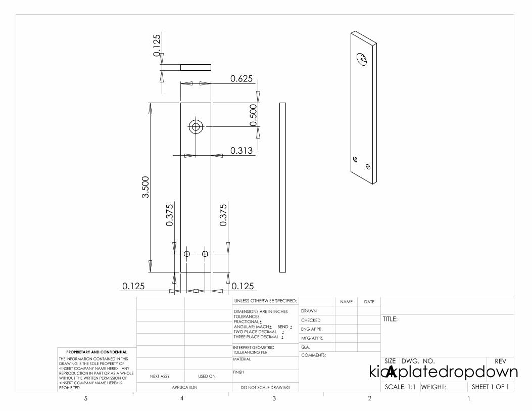
0.625
3.50
00.313
0.50
0
0.37
5
0.37
5
0.125 0.125
0.12
5
DO NOT SCALE DRAWING
kickplatedropdownSHEET 1 OF 1
UNLESS OTHERWISE SPECIFIED:
SCALE: 1:1 WEIGHT:
REVDWG. NO.
ASIZE
TITLE:
NAME DATE
COMMENTS:
Q.A.
MFG APPR.
ENG APPR.
CHECKED
DRAWN
FINISH
MATERIAL
INTERPRET GEOMETRICTOLERANCING PER:
DIMENSIONS ARE IN INCHESTOLERANCES:FRACTIONALANGULAR: MACH BEND TWO PLACE DECIMAL THREE PLACE DECIMAL
APPLICATION
USED ONNEXT ASSY
PROPRIETARY AND CONFIDENTIALTHE INFORMATION CONTAINED IN THISDRAWING IS THE SOLE PROPERTY OF<INSERT COMPANY NAME HERE>. ANY REPRODUCTION IN PART OR AS A WHOLEWITHOUT THE WRITTEN PERMISSION OF<INSERT COMPANY NAME HERE> IS PROHIBITED.
5 4 3 2 1

0.75
0
2.750
0.37
5
0.37
5
0.375
1.188
0.12
5
DO NOT SCALE DRAWING
kickplateSHEET 1 OF 1
UNLESS OTHERWISE SPECIFIED:
SCALE: 2:1 WEIGHT:
REVDWG. NO.
ASIZE
TITLE:
NAME DATE
COMMENTS:
Q.A.
MFG APPR.
ENG APPR.
CHECKED
DRAWN
FINISH
MATERIAL
INTERPRET GEOMETRICTOLERANCING PER:
DIMENSIONS ARE IN INCHESTOLERANCES:FRACTIONALANGULAR: MACH BEND TWO PLACE DECIMAL THREE PLACE DECIMAL
APPLICATION
USED ONNEXT ASSY
PROPRIETARY AND CONFIDENTIALTHE INFORMATION CONTAINED IN THISDRAWING IS THE SOLE PROPERTY OF<INSERT COMPANY NAME HERE>. ANY REPRODUCTION IN PART OR AS A WHOLEWITHOUT THE WRITTEN PERMISSION OF<INSERT COMPANY NAME HERE> IS PROHIBITED.
5 4 3 2 1

0.375
0.50
0
2.00
00.
750
0.25
0
0.50
0
DO NOT SCALE DRAWING
kickermountSHEET 1 OF 1
UNLESS OTHERWISE SPECIFIED:
SCALE: 2:1 WEIGHT:
REVDWG. NO.
ASIZE
TITLE:
NAME DATE
COMMENTS:
Q.A.
MFG APPR.
ENG APPR.
CHECKED
DRAWN
FINISH
MATERIAL
INTERPRET GEOMETRICTOLERANCING PER:
DIMENSIONS ARE IN INCHESTOLERANCES:FRACTIONALANGULAR: MACH BEND TWO PLACE DECIMAL THREE PLACE DECIMAL
APPLICATION
USED ONNEXT ASSY
PROPRIETARY AND CONFIDENTIALTHE INFORMATION CONTAINED IN THISDRAWING IS THE SOLE PROPERTY OF<INSERT COMPANY NAME HERE>. ANY REPRODUCTION IN PART OR AS A WHOLEWITHOUT THE WRITTEN PERMISSION OF<INSERT COMPANY NAME HERE> IS PROHIBITED.
5 4 3 2 1

1.75
0
1.500
0.420
0.62
5
0.750
0.6250.4380.
125
1.50
0
0.1250.125
0.125
0.37
5
0.37
5
0.7500.3750.750
0.75
0
0.12
5DO NOT SCALE DRAWING
dribblermountSHEET 1 OF 1
UNLESS OTHERWISE SPECIFIED:
SCALE: 1:1 WEIGHT:
REVDWG. NO.
ASIZE
TITLE:
NAME DATE
COMMENTS:
Q.A.
MFG APPR.
ENG APPR.
CHECKED
DRAWN
FINISH
MATERIAL
INTERPRET GEOMETRICTOLERANCING PER:
DIMENSIONS ARE IN INCHESTOLERANCES:FRACTIONALANGULAR: MACH BEND TWO PLACE DECIMAL THREE PLACE DECIMAL
APPLICATION
USED ONNEXT ASSY
PROPRIETARY AND CONFIDENTIALTHE INFORMATION CONTAINED IN THISDRAWING IS THE SOLE PROPERTY OF<INSERT COMPANY NAME HERE>. ANY REPRODUCTION IN PART OR AS A WHOLEWITHOUT THE WRITTEN PERMISSION OF<INSERT COMPANY NAME HERE> IS PROHIBITED.
5 4 3 2 1

0.750 in
1.00
0 in 0.
375
in
0.375 in
0.188 in
0.12
5 in
0.75
0 in
0.37
5 in
0.37
5 in
0.188 in0.188 in
0.209 in
0.12
5 in
DO NOT SCALE DRAWING
dribbleraxelmountSHEET 1 OF 1
UNLESS OTHERWISE SPECIFIED:
SCALE: 2:1 WEIGHT:
REVDWG. NO.
ASIZE
TITLE:
NAME DATE
COMMENTS:
Q.A.
MFG APPR.
ENG APPR.
CHECKED
DRAWN
FINISH
MATERIAL
INTERPRET GEOMETRICTOLERANCING PER:
DIMENSIONS ARE IN INCHESTOLERANCES:FRACTIONALANGULAR: MACH BEND TWO PLACE DECIMAL THREE PLACE DECIMAL
APPLICATION
USED ONNEXT ASSY
PROPRIETARY AND CONFIDENTIALTHE INFORMATION CONTAINED IN THISDRAWING IS THE SOLE PROPERTY OF<INSERT COMPANY NAME HERE>. ANY REPRODUCTION IN PART OR AS A WHOLEWITHOUT THE WRITTEN PERMISSION OF<INSERT COMPANY NAME HERE> IS PROHIBITED.
5 4 3 2 1

1.00
0 in
0.50
0 in
1.75
0 in
0.62
5 in
0.25
0 in
0.50
0 in
DO NOT SCALE DRAWING
dribblerSHEET 1 OF 1
UNLESS OTHERWISE SPECIFIED:
SCALE: 1:1 WEIGHT:
REVDWG. NO.
ASIZE
TITLE:
NAME DATE
COMMENTS:
Q.A.
MFG APPR.
ENG APPR.
CHECKED
DRAWN
FINISH
MATERIAL
INTERPRET GEOMETRICTOLERANCING PER:
DIMENSIONS ARE IN INCHESTOLERANCES:FRACTIONALANGULAR: MACH BEND TWO PLACE DECIMAL THREE PLACE DECIMAL
APPLICATION
USED ONNEXT ASSY
PROPRIETARY AND CONFIDENTIALTHE INFORMATION CONTAINED IN THISDRAWING IS THE SOLE PROPERTY OF<INSERT COMPANY NAME HERE>. ANY REPRODUCTION IN PART OR AS A WHOLEWITHOUT THE WRITTEN PERMISSION OF<INSERT COMPANY NAME HERE> IS PROHIBITED.
5 4 3 2 1

63
Appendix G
Selected Component Datasheets

II. DRAWING OF CURVES
Pout3.0
2.7
2.4
2.1
1.8
1.5
1.2
0.9
0.6
0.3
0.00
Kgcm1.0 2.0 3.0 4.0 5.0
Amp2.0
1.8
1.6
1.4
1.2
1.0
0.8
0.6
0.4
0.2
0.0
Eff1.0
0.9
0.8
0.7
0.6
0.5
0.4
0.3
0.2
0.1
0.0
kRPM0.30
0.27
0.24
0.21
0.18
0.15
0.12
0.09
0.06
0.03
0.00
kRPM
Pout
Amp
Eff
I. OUTER DIMENSIONS
III. SPECIFICATIONS
Type: HN-GH35GMAModel: HN-GH12-2217Y - 30:1
1. Testing Conditions:Temp: 25° CelsiusHumidity: 60%Motor Orientation: Horizontal
2. Rated Voltage: 12vdc3. Voltage Operating Range: 6-12vdc4. Rated Load at 12vdc: 620g-cm
Do not exceed rated load. Damage may occur!5. No Load Speed at 12vdc: 200 RPM +/- 10%
6. Speed at Rated Load (620g-cm): 177 RPM +/- 10%7. No Load Current at 12vdc: < 113mA8. Current at Rated Load (620g-cm): < 233mA9. Shaft End-Play: Maximum 0.8m/m10. Insulation Resistance: 10M ohm at 300vdc11. Withstand Voltage: 300vdc for 1 Second12. The gear motor is not intended for instant reverse.The gear motor must be stopped before reversing.13. The gear motor does not include protection fromwater or dust etc.
Data sheet for:GHM-0112vdc 30:1 200rpm6mm shaft
www.lynxmotion.com
18.5
4.6 18
12
29.5
48
4-M3
7

Prosilica Advantage
Prosilica’s EC-Series cameras are ultra-compact, high-performance CCD and CMOS cameras for machine vision and industrial applications. The EC-Series include fast frame-rate cameras in megapixel, 2-megapixel, and standard resolution models. Applications for the EC-Series cameras include machine vision, industrial inspection, character recognition, robotics, surveillance and OEM applications.
■ Excellent Products
■ Advanced Engineering
■ Great Software
■ Excellent Support
Features
• Ultra-compact size and light weight• Firewire interface • DCAM compliant (IIDC 1.31)• Region of interest readout• Snapshot shutter• External trigger and sync• Color and monochrome models• High-performance CCD and CMOS• Fast framerates• SDK and driver included• Color and monochrome• Binning• Rugged design• On-camera color interpolation
ultrA-comPAct firEwirE ccd & cmoS
High-performance CCD & CMOS Cameras for Machine Vision and Digital Imaging
Prosilica Inc. Tel: 604.875.8855 Fax: 604.875.8856 E-mail: [email protected]
EC SeriesFirewire (IEEE 1394)

Prosilica Inc. Suite 110, 8988 Fraserton [email protected] • www.prosilica.com Burnaby, BC Canada V5J 5H8 © Prosilica Inc. (09) 2006 All Rights Reserved Tel: 604.875.8855 • Fax: 604.875.8856
EC640 EC640C
EC650 EC650C
EC655 EC655C
EC750 EC750C
EC1020 EC1020C EC1280 EC1350
EC1350CEC1380
EC1380CEC1600
EC1600C
Resolution 659 × 480 659 × 493 659 × 493 752 × 480 1024 × 768 1280 × 1024 1360 × 1024 1360 × 1024 1620 × 1220
Frame Rate 97 fps 90 fps 90 fps 60 fps 30 fps 24 fps 18 fps 20 fps 15 fps
Sensor Type 1/2" CMOS 1⁄3" CCD 1/2" CCD 1⁄3" CMOS 1⁄3" CCD 2⁄3" CMOS 1/2" CCD 2⁄3" CCD 1⁄1.8" CCD
Sensor MT9V403 ICX424 ICX414 MT9V022 ICX204 IBIS5A ICX205 ICX285 ICX274
Pixel Size (um) 9.9 × 9.9 7.4 × 7.4 9.9 × 9.9 6.0 × 6.0 4.65 × 4.65 6.7 × 6.7 4.65 × 4.65 6.45 × 6.45 4.4 × 4.4
Readout Progressive Scan
Interface Type IEEE-1394 (Firewire)
Digital Interface DCAM (IIDC 1.31)
Mono/Color Yes/Yes Yes/No Yes/Yes
Color ModesMono8, Mono16, Bayer8, Bayer16,
RGB24, YUV4:1:1, YUV4:2:2 N/A
Mono8, Mono16, Bayer8, Bayer16,
RGB24, YUV4:1:1, YUV4:2:2
Mono8, Mono16, Bayer8, Bayer16
Imaging Modes Free-running, External trigger, Fixed frame rate, Software trigger
External Trigger Modes Rising edge, Falling edge, Level high, Level low
External Sync Modes Trigger ready, Trigger input, Exposing, GPO
Region of Interest Independent x, y control from 1 × 1 to full resolution
Binning N/A 2 × 2 N/A 2x2
Power Requirements 1.8 W 2.5 W 1.8 W 2.5 W 1.8 W 2.5 W 3 W
Conformity CE, FCC, RoHS
SDK Free of charge - includes driver
Specifications subject to change without notice.Please refer to Prosilica’s website for information on other camera models.
Prosilica’s EC Series ultra-compact Firewire cameras incorporate the latest interface technology and advanced camera features. These IIDC 1.31 compliant cameras are available in a wide range of resolutions, frame rates, and sensor formats.
EC Series

XBee Product FamilyThe XBee family of embedded RF modules provides OEMs with a common footprint shared bymultiple platforms, including multipoint and ZigBee/Mesh topologies, and both 2.4 GHz and900 MHz solutions. OEMs deploying the XBee can substitute one XBee for another, dependingupon dynamic application needs, with minimal development, reduced risk and shorter time-to-market.
Why XBee Multipoint RF Modules?XBee multipoint RF modules are ideal for applications requiring low latency and predictablecommunication timing. Providing quick, robust communication in point-to-point, peer-to-peer,and multipoint/star configurations, XBee multipoint products enable robust end-pointconnectivity with ease. Whether deployed as a pure cable replacement for simple serialcommunication, or as part of a more complex hub-and-spoke network of sensors,XBee multipoint RF modules maximize wireless performance and ease of development.
Drop-in Networking End-Point ConnectivityXBee OEM RF modules are part of Digi’s Drop-in Networking family of end-to-end connectivitysolutions. By seamlessly interfacing with compatible gateways, device adapters and extenders,XBee embedded RF modules provide developers with true beyond-the-horizon connectivity.
Providing critical end-point connectivity toDigi’s Drop-in Networking product family,XBee multipoint RF modules are low-cost andeasy to deploy.
Features/Benefits
www.digi.com
• 802.15.4/Multipoint network topologies
• 2.4 GHz for worldwidedeployment
• 900 MHz for long-rangedeployment
• Fully interoperable with other Digi Drop-in Networkingproducts, including gateways, device adapters and extenders
• Common XBee footprint for a variety of RF modules
• Low-power sleep modes
• Multiple antenna options
• Industrial temperature rating(-40º C to 85º C)
• Low power and long range variants available
Embedded RF Modules for OEMs
Product Datasheet
Overview
XBee® Multipoint RF Modules
Central FacilitiesManagement
Ethernet
ConnectPort™ XGatewayGaaatetetetewawawaw yy
9-30VDC
1A MAX
LINK
ACT
STATUS
POWER
RESET
PRIMARY
ANTENNA
SECONDARY
ANTENNA
SIGNAL STRENGTH
ConnectPort X4
WirelessTelco Network
Warehouse
Internet/Frame Relay/
VPN
Meter
Meter
PRO
PRO
Meter
PRO
XBee®
Module
802.15.4/Multipoint Wireless Networks

91001412B1/308
© 2006-2008 Digi International Inc.All rights reserved. Digi, Digi International, the Digi logo, the When Reliability Matters logo, XBee and XBee-PRO are trademarks or registeredtrademarks of Digi International Inc. in the United States and other countries worldwide. All other trademarks are the property of theirrespective owners.
Digi International11001 Bren Road E.Minnetonka, MN 55343U.S.A.PH: 877-912-3444
952-912-3444FX: 952-912-4952email: [email protected]
Digi InternationalFrance31 rue des Poissonniers92200 Neuilly sur Seine PH: +33-1-55-61-98-98 FX: +33-1-55-61-98-99www.digi.fr
Digi InternationalKKNES Building South 8F22-14 Sakuragaoka-cho,Shibuya-kuTokyo 150-0031, JapanPH: +81-3-5428-0261FX: +81-3-5428-0262www.digi-intl.co.jp
Digi International(HK) LimitedSuite 1703-05, 17/F.,K Wah Centre191 Java RoadNorth Point, Hong KongPH: +852-2833-1008FX: +852-2572-9989www.digi.cn
DIGI SERVICE AND SUPPORT - You can purchase with confidence knowing that Digi is here to support you with expert technical support and a one-year warranty. www.digi.com/support
Digi International, the leader in device networking for business, develops reliable products and technologies to connect and securely manage local or remote electronicdevices over the network or via the web. With over 20 million ports shipped worldwidesince 1985, Digi offers the highest levels of performance, flexibility and quality.
www.digi.com
WHEN
MATTERS™
* XBee-PRO 802.15.4 TX Power restricted to 10 mW in Europe and Japan.
Platform XBee® 802.15.4 (Series 1) XBee-PRO® 802.15.4 (Series 1) XBee-PRO® XSC
Performance
RF Data Rate 250 kbps 250 kbps 10 kbps / 9.6 kbps
Indor/Urban Range 100 ft (30 m) 300 ft (100 m) Up to 1200 ft (370 m)
Outdoor/RF Line-of-Sight Range 300 ft (100 m) 1 mi (1.6 km) Up to 6 mi (9.6 km)
Transmit Power 1 mW (+0 dBm) 60 mW (+18 dBm)* 100 mW (+20 dBm)
Receiver Sensitivity (1% PER) -92 dBm -100 dBm -106 dBm
Features
Serial Data Interface 3.3V CMOS UART 3.3V CMOS UART 3.3V CMOS UART (5V Tolerant)
Confi guration Method API or AT Commands, local or over-the-air API or AT Commands, local or over-the-air AT Commands
Frequency Band 2.4 GHz 2.4 GHz 902 MHz to 928 MHz
Interference Immunity DSSS (Direct Sequence Spread Spectrum) DSSS (Direct Sequence Spread Spectrum) FHSS (Frequency Hopping Spread Spectrum)
Serial Data Rate 1200 bps - 250 kbps 1200 bps - 250 kbps 1200 bps - 57.6 kbps
ADC Inputs (6) 10-bit ADC inputs (6) 10-bit ADC inputs None
Digital I/O 8 8 None
Antenna Options Chip, Wire Whip, U.FL, & RPSMA Chip, Wire Whip, U.FL, & RPSMA Wire Whip, U.FL, RPSMA
Networking & Security
Encryption 128-bit AES 128-bit AES No
Reliable Packet Delivery Retries/Acknowledgments Retries/Acknowledgments Retries/Acknowledgements
IDs and Channels PAN ID, 64-bit IEEE MAC, 16 Channels PAN ID, 64-bit IEEE MAC, 12 Channels PAN ID, 32-bit Address, 7 Channels
Power Requirements
Supply Voltage 2.8 - 3.4VDC 2.8 - 3.4VDC 3.0 - 3.6VDC
Transmit Current 45 mA @ 3.3VDC 215 mA @ 3.3VDC 265 mA typical
Receive Current 50 mA @ 3.3VDC 55 mA @ 3.3VDC 65 mA typical
Power-Down Current <10 uA @ 25º C <10 uA @ 25º C 45 uA pin Sleep
Regulatory Approvals
FCC (USA) OUR-XBEE OUR-XBEEPRO MCQ-XBEEXSC
IC (Canada) 4214A-XBEE 4214A-XBEEPRO 1846A-XBEEXSC
ETSI (Europe) Yes Yes* Max TX 10 mW No
C-TICK Australia Yes Yes No
Telec (Japan) Yes Yes* No
Please visit www.digi.com for part numbers.
802.15.4 – Star
(top view) (top view)
0.866”(22.00mm)
0.960”(24.38mm)
PIN 1
PIN 10 PIN 11
PIN 20 PIN 1
PIN 10 PIN 11
PIN 20
1.087”(27.61mm)
0.257”(6.53mm)
0.866”(22.00mm)
0.960”
1.297”(32.94mm)
0.299”(7.59mm)
(side views)
0.020”(0.51mm)
shield-to-PCB0.080” ±0.020(2.03mm ±0.51)
0.079”(2.00mm)
0.050”(1.27mm)
0.031”(0.79mm)
0.110”(2.79mm)
0.160”(4.06mm)
XBee XBee-PRO

II. DRAWING OF CURVES
Pout5.0
4.5
4.0
3.5
3.0
2.5
2.0
1.5
1.0
0.5
0.00
Kgcm1.8 3.6 5.4 7.2 9.0
Amp4.0
3.6
3.2
2.8
2.4
2.0
1.6
1.2
0.8
0.4
0.0
Eff1.0
0.9
0.8
0.7
0.6
0.5
0.4
0.3
0.2
0.1
0.0
kRPM0.20
0.18
0.16
0.14
0.12
0.10
0.08
0.06
0.04
0.02
0.00
kRPM
Pout
Amp
Eff
I. OUTER DIMENSIONS
III. SPECIFICATIONS
Type: HN-GH35GMBModel: HN-GH7.2-2414T - 50:1
1. Testing Conditions:Temp: 25° CelsiusHumidity: 60%Motor Orientation: Horizontal
2. Rated Voltage: 7.2vdc3. Voltage Operating Range: 6-7.2vdc4. Rated Load at 7.2vdc: 1.0Kg-cm
Do not exceed rated load. Damage may occur!5. No Load Speed at 7.2vdc: 175 RPM +/- 10%
6. Speed at Rated Load (1.0Kg-cm): 146 RPM +/- 10%7. No Load Current at 7.2vdc: < 221mA8. Current at Rated Load (1.0Kg-cm): < 556mA9. Shaft End-Play: Maximum 0.8m/m10. Insulation Resistance: 10M ohm at 300vdc11. Withstand Voltage: 300vdc for 1 Second12. The gear motor is not intended for instant reverse.The gear motor must be stopped before reversing.13. The gear motor does not include protection fromwater or dust etc.
Data sheet for:GHM-047.2vdc 50:1 175rpm6mm shaft
www.lynxmotion.com
1812
313.5±1
4.6
42 22.6 4-M3
7


64
Appendix H
RoboCup SSL 2010 Rules and Regulations

Laws of the F180 League 2009LAW 1 - The Field of PlayLAW 2 - The BallLAW 3 - The Number of RobotsLAW 4 - The Robotic EquipmentLAW 5 - The RefereeLAW 6 - The Assistant RefereeLAW 7 - The Duration of the MatchLAW 8 - The Start and Restart of PlayLAW 9 - The Ball In and Out of PlayLAW 10 - The Method of ScoringLAW 11 - OffsideLAW 12 - Fouls and MisconductLAW 13 - Free KicksLAW 14 - The Penalty KickLAW 15 - The Throw-InLAW 16 - The Goal KickLAW 17 - The Corner Kick
Appendix A - The Competition Rules
NotesMale and Female
References to the male gender in the Laws with respect to referees, assistant referees, teammembers and officials are for simplification and apply to both males and females.

LAW 1 - The Field of PlayDimensions
The field of play must be rectangular. The dimensions include boundary lines.
Length:6050mmWidth: 4050mm
Figure 1: The field dimensions
Field SurfaceThe playing surface is green felt mat or carpet. The floor under the carpet is level, flat and hard.
The field surface will continue for 675 mm beyond the boundary lines on all sides. The outer425mm of this runoff area are used as a designated referee walking area (see LAW 5). At theedge of the field surface, a 100 mm tall wall will prevent the ball and robots from running off theedge.
Field MarkingsThe field of play is marked with lines. Lines belong to the areas of which they are boundaries.
The two longer sides are called touch boundaries. The two shorter sides are called goalboundaries.
All lines are 10 mm wide and painted white.

The field of play is divided into two halves by a halfway line.
The centre mark is indicated at the midpoint of the halfway line. A circle with a diameter of 1000mm is marked around it.
The Defence AreaA defence area is defined at each end of the field as follows:
Two quarter circles with a radius of 500 mm are drawn on the field of play. These quarter circlesare connected by a line parallel to the goal line. The exact configuration is depicted in Fig. 1.
The area bounded by this arc and the goal line is the defence area.
Penalty MarkWithin each defence area a penalty mark is made 450 mm from the midpoint between thegoalposts and equidistant to them. The mark is a 10 mm diameter circle of white paint.
GoalsGoals must be placed on the centre of each goal boundary.
They consist of two 160 mm vertical side walls joined at the back by a 160 mm vertical rear wall.The inner face of the goal has to be covered with an energy absorbing material such as foam tohelp absorb ball impacts and lessen the speed of deflections. The goal walls, edges, and topsare white in color.
There is a round steel cross bar that runs across the top of the goalmouth and parallel to thegoal line. It is no larger than 10 mm in diameter, but is sufficiently strong to deflect the ball. Thebottom of the bar is 155 mm from the field surface, and the bar is dark in color to minimiseinterference with vision systems. The top of the goal is covered in a thin net to prevent the ballfrom entering the goal from above. It is attached securely to the cross bar and goal walls.
The distance between the side walls is 700 mm. The goal is 180 mm deep. The distance fromthe lower edge of the crosswire to the playing surface is 150 mm.
The floor inside the goalmouth is the same as the rest of the playing surface.
The goal walls are 20 mm thick.
Goals must be anchored securely to field surface.
Figure 2: The Goal in detail

Equipment Mounting BarA mounting bar will be provided 4 m above the field. The bar will run above the midline of thefield from goal to goal. The bar should mounted securely so that it does not swing or sway undera small external force, and it should not bend or twist significantly when the weight of typicalvideo equipment is added.
Decisions of the F180 Technical CommitteeDecision 1The local organising committee should aim to provide uniform, diffuse lighting conditions ofapproximately 500 LUX or brighter. No special lighting equipment will necessarily be used toprovide these conditions. The brightness is not guaranteed nor expected to be fully uniformacross the field surface. Teams are thus expected to cope with the variations that will occurwhen using ambient lighting. The organising committee will release details of the lightingarrangements to the competitors as early as practical.
Decision 2No kind of commercial advertising, whether real or virtual, is permitted on the field of play andfield equipment (including the goal nets and the areas they enclose) from the time the teamsenter the field of play until they have left it at half-time and from the time the teams re-enter thefield of play until the end of the match. In particular, no advertising material of any kind may bedisplayed inside the goals or walls. No extraneous equipment (cameras, microphones, etc.) maybe attached to these items.
Decision 3The specific colour and texture of the surface is not specified and may vary from competition tocompetition (just as real soccer fields vary). The surface underneath the carpet will be level andhard. Examples of approved surfaces include: cement, linoleum, hardwood flooring, plywood,ping-pong tables and particle board; carpeted or cushioned surfaces are not allowed. Everyeffort shall be made to ensure that the surface is flat; however, it is up to individual teams todesign their robots to cope with slight curvatures of the surface.

LAW 2 - The BallQualities and Measurements
The ball is a standard orange golf ball. It is:sphericalorange in colourapproximately 46 g in massapproximately 43 mm in diameter
Replacement of a Defective BallIf the ball becomes defective during the course of a match:
the match is stoppedthe match is restarted by placing the replacement ball at the place where the first ball became
defective
If the ball becomes defective whilst not in play at a kick-off, goal kick, corner kick, free kick,penalty kick or throw-in:
the match is restarted accordingly
The ball may not be changed during the match without the authority of the referee.

LAW 3 - The Number of RobotsRobots
A match is played by two teams, each consisting of not more than five robots, one of which maybe the goalkeeper. Each robot must be clearly numbered so that the referee can identify themduring the match. The goalkeeper must be designated before the match starts. A match may notstart unless both teams have at least one robot.
InterchangeRobots may be interchanged. There is no limit on the number of interchanges.
Interchange ProcedureTo interchange a robot, the following conditions must be observed:
interchange can only be made during a stoppage in play,the referee is informed before the proposed interchange is made,the interchange robot enters the field of play after the robot being replaced has been removed,interchange robot enters the field of play at the halfway line.
Changing the GoalkeeperAny of the other robots may change places with the goalkeeper, provided that:
the referee is informed before the change is madethe change is made during a stoppage in the match
Robots Sent OffA robot that has been sent off may interchange for another robot that leaves the field.
Decisions of the F180 Technical CommitteeDecision 1Each team must have a single designated robot handler to perform interchange and robotplacing when required. No other team members can encroach upon the area immediatelysurrounding the field. Movement of robots by the handler is not allowed.

LAW 4 - The Robotic EquipmentSafety
A robot must not have in its construction anything that is dangerous to itself, another robot orhumans.
ShapeA robot must fit inside a 180 mm diameter cylinder and have a height of 150 mm or less.
Figure 3: The maximum robot dimensions
Colours and MarkersBefore a game, each of the two teams has a colour assigned, namely yellow or blue. Each teammust be able to use yellow and blue markers. Circular markers of the assigned colour must bemounted on top of the robots. The centre of the marker must be located in the visual centre ofthe robot when viewed from above. The markers must have a diameter of 50 mm.
Robots may use black and white colouring without restriction. Robots may also use light green,light pink and cyan markers.
LocomotionRobot wheels (or other surfaces that contact the playing surface) must be made of a materialthat does not harm the playing surface.
Wireless CommunicationRobots can use wireless communication to computers or networks located off the field.
Global Vision SystemThe use of a global vision system or external distributed vision systems are permitted, but notrequired, to identify and track the position of robots and ball. This is achieved by using one ormore cameras. Cameras may not protrude more than 150 mm below the bottom of the mountingbeam provided above the field (Law 1).
AutonomyThe robotic equipment is to be fully autonomous. Human operators are not permitted to enterany information into the equipment during a match, except at half time or during a time-out.
Dribbling

Dribbling devices that actively exert backspin on the ball, which keep the ball in contact with therobot are permitted under certain conditions. The spin exerted on the ball must be perpendicularto the plane of the field. Vertical or partially vertical dribbling bars, also known as side dribblers,are not permitted. The use of dribbling devices is also restricted as per Law 12, Indirect FreeKicks.
Figure 4: How a dribbler may work (check figure 5 for further detail on the 20% rule)
Infringements/SanctionsFor any infringement of this Law:
play need not be stoppedthe robot at fault is instructed by the referee to leave the field of play to correct its equipmentthe robot leaves the field of play when the ball next ceases to be in playany robot required to leave the field of play to correct its equipment does not re-enter without
the referee's permissionthe referee checks that the robot's equipment is correct before allowing it to re-enter the field
of playthe robot is only allowed to re-enter the field of play when the ball is out of play
A robot that has been required to leave the field of play because of an infringement of this Lawand that enters (or re-enters) the field of play without the referee's permission is cautioned andshown the yellow card.
Restart of PlayIf play is stopped by the referee to administer a caution:
the match is restarted by an indirect free kick taken by a robot of the opposing side, from theplace where the ball was located when the referee stopped the match
Decisions of the F180 Technical CommitteeDecision 1Participants using wireless communications shall notify the local organising committee of the

method of wireless communication, power, and frequency. The local organising committee shallbe notified of any change after registration as soon as possible.
In order to avoid interference, a team should be able to select from two carrier frequenciesbefore the match. The type of wireless communication shall follow legal regulations of thecountry where the competition is held. Compliance with local laws is the responsibility of thecompeting teams, not the RoboCup Federation. The type of wireless communication may alsobe restricted by the local organising committee. The local organising committee will announceany restrictions to the community as early as possible.
Decision 2Kicking devices are permitted.
Decision 3Metal spikes and Velcro are specifically prohibited for the purpose of locomotion.
Decision 4Bluetooth wireless communication is not allowed.
Decision 5Official colours will be provided by the organising committee. Teams must use the officialcolours unless both teams agree not to.
Decision 6Adhesives such as glue or tape may not be used for the purpose of ball control or to constructdribblers. Dribbling devices which use such an adhesive to affix the ball to a robot areconsidered a violation of Law 12, Decision 4, by "removing all of the degrees of freedom of theball". In addition, the use of adhesives for any purpose on the robot which results in residue lefton the ball or field, is considered as damage and sanctioned as per Law 12.
Decision 7A rules check will be performed on all robots at the competition prior to the first match. Anyteam's robot which is found to violate a rule must be modified to be compliant before it canparticipate in matches.

LAW 5 - The RefereeThe Authority of the Referee
Each match is controlled by a referee who has full authority to enforce the Laws of the Game inconnection with the match to which he has been appointed.
Powers and DutiesThe Referee:
enforces the Laws of the Gamecontrols the match in co-operation with the assistant refereesensures that any ball used meets the requirements of Law 2ensures that the robotic equipment meets the requirements of Law 4informs the assistant referees when periods of time lost begin and end in accordance with
Law 7stops, suspends or terminates the match, at his discretion, for any infringements of the Lawsstops, suspends or terminates the match because of outside interference of any kindstops the match if, in his opinion, a robot is likely to cause serious harm to humans, other
robots or itself and ensures that it is removed from the field of playrepositions the ball to a neutral position if it becomes stuck during playallows play to continue when the team against which an offence has been committed will
benefit from such an advantage and penalises the original offence if the anticipated advantagedoes not ensue at that time
punishes the more serious offence when a robot commits more than one offence at the sametime
takes disciplinary action against robots guilty of cautionable and sending-off offences. He isnot obliged to take this action immediately but must do so when the ball next goes out of play
takes action against team officials who fail to conduct themselves in a responsible mannerand may at his discretion, expel them from the field of play and its immediate surrounds
acts on the advice of assistant referees regarding incidents which he has not seenensures that no unauthorised persons encroach the field of playrestarts the match after it has been stoppedprovides the technical committee with a match report which includes information on any
disciplinary action taken against team officials and any other incidents which occurred before,during or after the match
Decisions of the RefereeThe decisions of the referee regarding facts connected with play are final.
The referee may only change a decision on realising that it is incorrect or, at his discretion, onthe advice of an assistant referee, provided that he has not restarted play.
Referee's Signalling EquipmentA device will be supplied to convert the referee's signals into both serial and ethernetcommunication signals that are transmitted to both teams. The equipment will be operated bythe assistant referee. Details of the equipment are to be supplied by the local organisingcommittee before the competition.
Signals from the Referee

During a match the referee will signal the start and stop of play in the usual fashion. Theassistant referee will send signals reflecting the referee's call over communication links to eachteam. No interpretation of the referee's signals by human operators is permitted.
The whistle signal indicates that the referee has stopped play, and that all robots should move500 mm from the ball to allow the referee to place the ball for a restart. All robots are required toremain 500 mm from the ball as the ball is moved to the restart position.
For a goal (Law 10), or caution or send off (Law 12), an informational signal will be sent toindicate the referee's decision.
The restart signal will indicate the type of restart. Robots should move into legal positions uponreceipt of this signal. For restarts other than a kick-off (Law 8) or a penalty kick (Law 14), thekicker may kick the ball when ready without further signals from the referee.
For a kick-off (Law 8) or a penalty kick (Law 14), a start signal will be sent to indicate that thekicker may proceed. This signal will not be sent for other types of restart.
Signals indicating periods of time-out and time lost will also be sent when required.
The referee will be deemed to have given a signal when the assistant referee has relayed thatsignal over the communications links.
Decisions of the F180 Technical CommitteeDecision 1A referee (or where applicable, an assistant referee) is not held liable for:
any kind of injury suffered by an official or spectatorany damage to property of any kindany other loss suffered by any individual, club, company, association or other body, which is
due or which may be due to any decision which he may take under the terms of the Laws of theGame or in respect of the normal procedures required to hold, play and control a match.
This may include:a decision that the condition of the field of play or its surrounds are such as to allow or not to
allow a match to take placea decision to abandon a match for whatever reasona decision as to the condition of the fixtures or equipment used during a match including the
field and the balla decision to stop or not to stop a match due to spectator interference or any problem in the
spectator areaa decision to stop or not to stop play to allow a damaged robot to be removed from the field of
play for repaira decision to request or insist that a damaged robot be removed from the field of play for
repaira decision to allow or not to allow a robot to have certain coloursa decision (in so far as this may be his responsibility) to allow or not to allow any persons
(including team or stadium officials, security officers, photographers or other mediarepresentatives) to be present in the vicinity of the field of play
any other decision which he may take in accordance with the Laws of the Game or inconformity with his duties under the terms of the RoboCup Federation or league rules or

regulations under which the match is played
Decision 2Facts connected with play shall include whether a goal is scored or not and the result of thematch.
Decision 3The referee should use a black stick or some other device when repositioning the ball to reducethe chance of interference with vision systems.
Decision 4The referee may be assisted by an autonomous referee application provided by one or both ofthe competing teams, if both teams agree. The referee may also be assisted by an autonomousor semi-autonomous application provided by a team not participating in the current match, at thereferee's own discretion, provided that the application is operated or monitored by a neutralparty.
Decision 5The outer region of the field surface which is further than 250mm away from the boundary line isused as a designated walking area by the referee and/or assistant referee during gameplay.Teams should control their robots to stay out of this area to not interfere with the referees.Referees are not responsible for any obstructions to robots or vision systems within this area.Nevertheless, referees are requested to wear clothes and shoes which do not contain any colorreserved for the ball or for robot markers.

LAW 6 - The Assistant RefereeDuties
The assistant referee is appointed whose duties, subject to the decision of the referee, are to:act as timekeeper and keep a record of the matchto operate the communications equipment to relay the referee's signals over the
communications linksmonitor the robot operators for illegal signals being sent to the robotsindicate when an interchange is requestedindicate when misconduct or any other incident has occurred out of the view of the refereeindicate when offences have been committed whenever the assistants are closer to the action
than the referee (this includes, in particular circumstances, offences committed in the defencearea)
indicate whether, at penalty kicks, the goalkeeper has moved forward before the ball has beenkicked and if the ball has crossed the line
AssistanceThe assistant referees also assist the referee to control the match in accordance with the Lawsof the Game. In the event of undue interference or improper conduct, the referee will relieve anassistant referee of his duties and make a report to the organising committee.
Decision 1A second assistant referee will be used whenever possible. The second assistant referee willhelp the referee in ball placement on the field, as well as helping monitor compliance with alllaws and procedures.

LAW 7 - The Duration of the MatchPeriods of Play
The match lasts two equal periods of 10 minutes, unless otherwise mutually agreed betweenthe referee and the two participating teams. Any agreement to alter the periods of play (forexample, to reduce each half to 7 minutes because of a limited schedule) must be made beforethe start of play and must comply with competition rules.
Half-Time IntervalTeams are entitled to an interval at half time. The half-time interval must not exceed 5 minutes.Competition rules must state the duration of the half-time interval. The duration of the half-timeinterval may be altered only with the consent of both teams and the referee.
TimeoutsEach team is allocated four timeouts at the beginning of the match. A total of 5 minutes isallowed for all timeouts. For example, a team may take three timeouts of one-minute durationand thereafter have only one timeout of up to two minutes duration. Timeouts may only be takenduring a game stoppage. The time is monitored and recorded by the assistant referee.
Allowance for Time LostAllowance is made in either period for all time lost through:
substitution(s)assessment of damage to robotsremoval of damaged robots from the field of play for treatmentwasting timeany other cause
The allowance for time lost is at the discretion of the referee.
Extra TimeCompetition rules may provide for two further equal periods to be played. The conditions of Law8 will apply.
Abandoned MatchAn abandoned match is replayed unless the competition rules provide otherwise.
Decisions of the F180 Technical CommitteeDecision 1The local organising committee will make every effort to provide both teams access to thecompetition area at least two hours before the start of the competition. They will also strive toallow at least one hour of setup time before each match. Participants should be aware, however,that conditions may arise where this much time cannot be provided.
Decision 2Within these rules, the term "game stoppage" is used to describe the times when the gameplayis in a stopped state. Gameplay is not considered stopped when any robot is allowed to kick theball. For example, gameplay is stopped after the "Kickoff" command has been issued, but it is

no longer stopped after the corresponding "Ready" command has been issued. Similarly,gameplay is no longer stopped after a "Freekick" has been issued.

LAW 8 - The Start and Restart of PlayPreliminaries
If both teams have a common preferred frequency for wireless communications, the localorganising committee will allocate that frequency for the first half of the match. If both teamshave a common preferred color, the local organising committee will allocate the color for the firsthalf of the match.
A coin is tossed and the team which wins the toss decides which goal it will attack in the firsthalf of the match.
The other team takes the kick-off to start the match.
The team that wins the toss takes the kick-off to start the second half of the match.
In the second half of the match the teams change ends and attack the opposite goals. Teamsmay agree not to change ends and attack the opposite goals with the consent of the referee.
If both teams have a common preferred frequency for wireless communications, the teamsshould swap the allocation of that frequency for the second half of the match. Teams may agreenot to change the allocation of the preferred frequency with the consent of the referee.
If both teams have a common preferred marker color, the teams should swap marker colors forthe second half of the match. Teams may agree not to change the marker colors with theconsent of the referee.
Kick-offA kick-off is a way of starting or restarting play:
at the start of the matchafter a goal has been scoredat the start of the second half of the matchat the start of each period of extra time, where applicable
A goal may be scored directly from the kick-off.
Procedureall robots are in their own half of the fieldthe opponents of the team taking the kick-off are at least 500 mm from the ball until the ball is
in playthe ball is stationary on the centre markthe referee gives a signalthe ball is in play when is kicked and moves forwardthe kicker does not touch the ball a second time until it has touched another robot
After a team scores a goal, the kick-off is taken by the other team.
Infringements/SanctionsAny infringement as listed in Law 9 is handled accordingly
For any other infringement of the kick-off procedure:the kick-off is retaken

Placed BallA placed ball is a way of restarting the match after a temporary stoppage which becomesnecessary, while the ball is in play, for any reason not mentioned elsewhere in the Laws of theGame.
ProcedureThe referee places the ball at the place where it was located when play was stopped. By Law 9,all robots are required to remain 500mm from the ball while the ball is being placed. Playrestarts when the referee gives a signal.
Infringements/SanctionsThe ball is placed again:
if a robot comes within 500 mm of the ball before the referee gives the signal
Special CircumstancesA free kick awarded to the defending team inside its own defence area is taken from a legal freekick position nearest to where the infringement occurred.
A free kick awarded to the attacking team in its opponents' defence area is taken from a legalfree kick position nearest to where the infringement occurred.
A placed ball to restart the match after play has been temporarily stopped inside the defencearea takes place on the a legal free kick position nearest to where the ball was located whenplay was stopped.

LAW 9 - The Ball In and Out of PlayBall Out of Play
The ball is out of play when: it has wholly crossed the goal boundary or touch boundary whether on the ground or in the airplay has been stopped by a signal from the referee
When the ball goes out of play, robots should remain 500 mm from the ball as the ball is placed,until the restart signal is given by the referee.
Ball In PlayThe ball is in play at all other times.
Infringements/SanctionsIf, at the time the ball enters play, a member of the kicker's team occupies the area closer than200 mm to the opponent's defense area:
an indirect free kick is awarded to the opposing team, the kick to be taken from the location ofthe ball when the infringement occurred * (see Law 13)
If, after the ball enters play, the kicker touches the ball a second time (without holding the ball)before it has touched another robot:
an indirect free kick is awarded to the opposing team, the kick to be taken from the placewhere the infringement occurred * (see Law 13)
If, after the ball enters play, the kicker deliberately holds the ball before it has touched anotherrobot:
a direct free kick is awarded to the opposing team, the kick to be taken from the place wherethe infringement occurred * (see Law 13)
If, after a signal to restart play is given, the ball does not enter play within 10 seconds, or lack ofprogress clearly indicates that the ball will not enter play within 10 seconds:
the play is stopped by a signal from the referee,all robots have to move 500 mm from the ball, anda neutral restart is indicated
Decisions of the F180 Technical CommitteeDecision 1For all restarts where the Laws stipulate that the ball is in play when it is kicked and moves, therobot must clearly tap or kick the ball to make it move. It is understood that the ball may remainin contact with the robot or be bumped by the robot multiple times over a short distance whilethe kick is being taken, but under no circumstances should the robot remain in contact or touchthe ball after it has traveled 50 mm, unless the ball has previously touched another robot.Robots may use dribbling and kicking devices in taking the free kick.
Decision 2The exclusion zone closer than 200mm to the opponent's defense area during restarts isdesigned to allow defending teams to position a defense against a kick without interference from

the opponents. This change was added to help teams defend against corner kicks in whichteams use elevated "chip kick" passes directly into the defense area.

LAW 10 - The Method of ScoringGoal Scored
A goal is scored when the whole of the ball passes over the goal line, between the goal walls,below the cross bar, provided that no infringement of the Laws of the Game has beencommitted previously by the team scoring the goal.
Winning TeamThe team scoring the greater number of goals during a match is the winner. If both teams scorean equal number of goals, or if no goals are scored, the match is drawn.
Competition RulesFor matches ending in a draw, competition rules may state provisions involving extra time, orother procedures approved by the RoboCup Federation to determine the winner of a match.
LAW 11 - OffsideOffside Rule
The offside rule is not adopted.

LAW 12 - Fouls and MisconductFouls and misconduct are penalised as follows:
Direct Free KickA direct free kick is awarded to the opposing team if a robot commits any of the following fouroffences:
makes substantial contact with an opponentholds an opponentholds the ball deliberately (except for the goalkeeper within his own defence area)is the second defending robot to simultaneously occupy the team's defence area in such a
way to substantially affect game play
A free kick is taken from where the offence occurred.
Penalty KickA penalty kick is awarded if any of the above four offences is committed by a robot inside hisown defence area, irrespective of the position of the ball, provided it is in play.
Indirect Free KicksAn indirect free kick is awarded to the opposing team if a goalkeeper, inside his own defencearea, commits any of the following offences:
takes more than fifteen seconds while holding the ball before releasing it from his possessionholds the ball again after it has been released from his possession and has not touched any
other robot
An indirect free kick is also awarded to the opposing team if a robot:contacts the goalkeeper where the point of contact is in the defence areadribbles the ball over a distance greater than 500 mmtouched the ball such that the top of the ball travels more than 150 mm from the ground, and
the ball subsequently enters their opponent's goal, without having either touched a teammate(while below 150 mm) or remained in contact with the ground (stopped bouncing).
kicks the ball such that it exceeds 10 m/s in speedcommits any other offence, not previously mentioned in Law 12, for which play is stopped to
caution or dismiss a robot
The free kick is taken from where the offence occurred.
Disciplinary SanctionsCautionable Offences
A team is cautioned and shown the yellow card if a robot on that team commits any of thefollowing six offences:1. is guilty of unsporting behaviour2. is guilty of serious and violent contact3. persistently infringes the Laws of the Game4. delays the restart of play5. fails to respect the required distance when play is restarted with a goal kick, corner kick orfree kick

6. modifies or damages the field or ball7. deliberately enters or travels within the referee walking area
Upon receipt of a yellow card, one robot of the penalised team must immediately move off andbe removed from the field. After two minutes of play (as measured by the assistant referee usingthe official game time) the robot may reenter the field at the next stoppage of play.
Sending-Off OffencesA team is shown a red card if one of the robots or the team is guilty of severe unsportingbehaviour. The number of robots on the team is reduced by one after every red card.
Decisions of the F180 Technical CommitteeDecision 1Substantial contact is contact sufficient to dislodge the robot from its current orientation,position, or motion in the case where it is moving. When both robots are moving at similarspeeds, and the cause of contact is not obvious, the referee will allow play to continue. This lawis designed to protect robots which are slow moving or stationary at the time of the contact, andas such should be detected by obstacle avoidance systems.
Decision 2Cautions for serious and violent contact are a way to discourage teams from ignoring the spiritof the no-contact principle. Examples of cautionable offences include uncontrolled motion, poorobstacle avoidance, pushing, or rapid spinning while adjacent to an opponent. In a typicalscenario, the referee would warn the team, and expect that they would modify their system toreduce the violence of their play. If the referee was still unsatisfied a caution would be issued.
Decision 3A robot that is placed on the field but is clearly not capable of movement will be sanctioned forunsporting behaviour.
Decision 4A robot is holding a ball if it takes full control of the ball by removing all of its degrees offreedom; typically, fixing a ball to the body or surrounding a ball using the body to preventaccess by others. 80% of the area of the ball when viewed from above should be outside theconvex hull around the robot. Another robot must be able to remove the ball from a robot withthe ball. This limitation applies as well to all dribbling and kicking devices, even if suchinfringement is momentary.

Figure 5: The 80/20 ball covering/holding rule
Decision 5A robot begins dribbling when it makes contact with the ball and stops dribbling when there is anobservable separation between the ball and the robot.
The restriction on dribbling distance was added to prevent a robot with a mechanically superiordribbler having unchallenged control of the ball. The distance restriction still allows dribblers tobe used to aim and receive passes, turn around with the ball, and stop with the ball. Dribblerscan still be used to dribble large distances with the ball as long as the robot periodically losespossession, such as kicking the ball ahead of it as human soccer players often do. Thetechnical committee expects the distance rule to be self-enforced, i.e., teams will insure theirsoftware complies beforehand and may be asked to demonstrate this prior to a competition.Referees, though, will still call fouls for violations and may give a caution (yellow card) forsituations of repeated violations.
Decision 6The limitation to kicking speed was added to prevent a robot with a mechanically superior kickerfrom having too great of an advantage over opponents, or kicking the ball at speed unsafe forspectators. It is also believed that this will help encourage team play over single robot ability, ina similar way to the restrictions on dribbling.
Decision 7The current rule about scoring after chip kicks is defined in this section (subsection Indirect FreeKicks) only. During past competitions, some confusions occurred after robots chipped the balland thereby caused own goals. For this reason, a strict interpretation of this rule is providedhere:
If a robot chips the ball (no matter at which height it travels) at a team mate and the ballsubsequently enters the own goal, the opponent team scores.If a robot chips the ball at an opponent and the ball subsequently enters the own goal whilestaying below 150mm all the time after touching the opponent robot, the opponent team alsoscores.If a robot chips the ball at an opponent and the ball subsequently enters the own goal afterhaving been above 150mm for some time (and not being in constant touch with the groundafterwards) after touching the opponent robot, the opponent team does not score.

Decision 8The offence on deliberately entering the referee walking area was added to discourage teamsfrom driving through this area to gain tactical advantages. In particular, it should prevent teamsfrom exploiting the fact that other teams might not have vision coverage of the referee walkingarea. It is understood that on occasion a robot can enter the area if it is out of control, or if it hasbeen pushed into this area. Such cases should not be considered offences. However, the finaldecision as to what constitutes a deliberate violation is left to the referee.

LAW 13 - Free KicksTypes of Free Kicks
Free kicks are either direct or indirect.
For both direct and indirect free kicks, the ball must be stationary when the kick is taken and thekicker does not touch the ball a second time until it has touched another robot.
The Direct Free Kickif a free kick is kicked directly into the opponents' goal, a goal is awarded.if a free kick is kicked directly into the team's own goal, a goal is awarded against the team.
The Indirect Free KickBall Enters the Goal
A goal can be scored only if the ball subsequently touches another robot before it enters thegoal.
if an indirect free kick is kicked directly into the opponents' goal, a goal kick is awardedif an indirect free kick is kicked directly into the team's own goal, a corner kick is awarded to
the opposing team
Free Kick ProcedureIf the free kick is awarded inside the defence area, the free kick is taken from a point 600 mmfrom the goal line and 100 mm from the touch line closest to where the infringement occurred.
If the free kick is awarded to the attacking team within 700 mm of the defence area, the ball ismoved to the closest point 700 mm from the defence area.
Otherwise the free kick is taken from the place where the infringement occurred.
All opponent robots are at least 500 mm from the ball.
The ball is in play when it is kicked and moves.
Infringements/SanctionsIf, when a free kick is taken, an opponent is closer to the ball than the required distance:
the kick is retaken
Any infringement as listed in Law 9 is handled accordingly
For any other infringement of this Law:
the kick is retaken

LAW 14 - The Penalty KickA penalty kick is awarded against a team which commits one of the five offences for which adirect free kick is awarded, inside its own defence area and while the ball is in play.
A goal may be scored directly from a penalty kick.
Additional time is allowed for a penalty kick to be taken at the end of each half or at the end ofperiods of extra time.
Position of the Ball and the RobotsThe ball:
is placed on the penalty mark
The robot taking the penalty kick:
is properly identified
The defending goalkeeper:
remains between the goalposts, touches its goal line, and faces outward of the goal, until theball has been kicked. It is allowed to move before the ball has been kicked, as long as its motiondoes not break any of these constraints.
The robots other than the kicker are located:
inside the field of playbehind a line parallel to the goal line and 400 mm behind the penalty mark
The Refereedoes not signal for a penalty kick to be taken until the robots have taken up position in
accordance with the Lawdecides when a penalty kick has been completed
Procedurethe robot taking the penalty kicks the ball forwardit does not play the ball a second time until it has touched another robotthe ball is in play when it is kicked and moves forward
When a penalty kick is taken during the normal course of play, or time has been extended athalf-time or full time to allow a penalty kick to be taken or retaken, a goal is awarded if, beforepassing between the goalposts and under the crossbar:
the ball touches either or both of the goalposts and/or the crossbar, and/or the goalkeeper
Infringements/SanctionsIf the referee gives the signal for a penalty kick to be taken and, before the ball is in play, one ofthe following situations occurs:
The robot taking the penalty kick infringes the Laws of the Game:
the referee allows the kick to proceed

if the ball enters the goal, the kick is retakenif the ball does not enter the goal, the kick is not retaken
The goalkeeper infringes the Laws of the Game:
the referee allows the kick to proceedif the ball enters the goal, a goal is awardedif the ball does not enter the goal, the kick is retaken
A team-mate of the robot taking the kick enters the area 400 mm behind the penalty mark:
the referee allows the kick to proceedif the ball enters the goal, the kick is retakenif the ball does not enter the goal, the kick is not retakenif the ball rebounds from the goalkeeper, the crossbar or the goal post and is touched by this
robot, the referee stops play and restarts the match with an indirect free kick to the defendingteam
A team-mate of the goalkeeper enters the area 400mm behind the penalty mark:
the referee allows the kick to proceedif the ball enters the goal, a goal is awardedif the ball does not enter the goal, the kick is retaken
A robot of both the defending team and the attacking team infringe the Laws of the Game:
the kick is retaken
If, after the penalty kick has been taken:
Any infringement as listed in Law 9 is handled accordingly
The ball is touched by an outside agent as it moves forward:
the kick is retaken
The ball rebounds into the field of play from the goalkeeper, the crossbar or the goalposts, andis then touched by an outside agent:
the referee stops playplay is restarted with a dropped ball at the place where it touched the outside agent* (see Law
13)

LAW 15 - The Throw-InA throw-in is a method of restarting play.
A goal cannot be scored directly from a throw-in.
A throw-in is awarded:
when the whole of the ball passes over the touch boundary, either on the ground or in the airfrom the point 100 mm perpendicular to the touch boundary where the ball crossed the touch
boundaryto the opponents of the robot that last touched the ball
ProcedureThe referee places the ball at the designated position.All opponent robots are at least 500 mm from the ball.The ball is in play when it is kicked and moves.
Infringements/SanctionsIf, when a throw-in is taken, an opponent is closer to the ball than the required distance:
the throw-in is retaken
Any infringement as listed in Law 9 is handled accordingly
For any other infringement:
the kick is retaken
LAW 16 - The Goal KickA goal kick is a method of restarting play.
A goal may be scored directly from a goal kick, but only against the opposing team.
A goal kick is awarded when:
the whole of the ball, having last touched a robot of the attacking team, passes over the goalboundary, either on the ground or in the air, and a goal is not scored in accordance with Law 10.
Procedurethe ball is kicked from a point 500 mm from the goal line and 100 mm from the touch line
closest to where the ball passed over the goal boundaryopponents remain 500 mm from the ball until the ball is in playthe kicker does not play the ball a second time until it has touched another robotthe ball is in play when it is kicked and moves
Infringements/SanctionsAny infringement as listed in Law 9 is handled accordingly
For any other infringement of this Law:
the kick is retaken

LAW 17 - The Corner KickA corner kick is a method of restarting play.
A goal may be scored directly from a corner kick, but only against the opposing team.
A corner kick is awarded when:
the whole of the ball, having last touched a robot of the defending team, passes over the goalline, either on the ground or in the air, and a goal is not scored in accordance with Law 10
Procedurethe ball is kicked from the nearest corner, 100mm in from both the goal line and the touch lineopponents remain 500 mm from the ball until the ball is in playthe kicker does not play the ball a second time until it has touched another robotthe ball is in play when it is kicked and moves
Infringements/SanctionsAny infringement as listed in Law 9 is handled accordingly
For any other infringement:
the kick is retaken

Appendix A - The Competition RulesThis appendix describes additional procedures for Small Size League matches.
Extra TimeIf the game is drawn after the end of the second period and the game needs to end with a clearwinner, extra time will be played (as stated in laws 7 and 10). Before the first half of extra time,there will be an interval that must not exceed 5 minutes.
Periods of Play in extra timeThe extra time lasts two equal periods of 5 minutes, unless otherwise mutually agreed betweenthe referee and the two participating teams. Any agreement to alter the periods of extra time (forexample, to reduce each half to 3 minutes because of a limited schedule) must be made beforethe start of play and must comply with competition rules.
Extra time half-time IntervalTeams are entitled to an interval at half-time. The half-time interval must not exceed 2 minutes.The duration of the half-time interval may be altered only with the consent of both teams and thereferee.
TimeoutsEach team is allocated two timeouts at the beginning of extra time. A total of 5 minutes isallowed for all timeouts. The number of timeouts and the time not used in regular game are notadded. Timeouts in extra time follow the same rules as in regular game (stated in law 7).
Penalty Shoot-OutIf the game is drawn after the end of the second period of extra time, kicks from the penaltymark will be taken to decide which teams wins the game.
PreparationBefore the first penalty is kicked, there will be an interval that must not exceed 2 minutes. Thistime is suggested to be used by the teams in dialogue with the referee and his assistants tocheck whether the goalie's position is correct (on the line) and all other rules for penalty can befullfilled as stated in law 14. The referee determines (e.g. by flipping a coin) which team defendswhich goal as well as which team has to take the first penalty kick.
ProcedureDuring the kicks from the penalty mark, a maximum of 2 robots per team is on the field in orderto avoid interference. The kicks from the penalty mark are taken alternately by the teams untileach team has kicked 5 penalties. If a decision is reached for one team, the kicks are stoppedby the referee. For all penalties, the rules of law 14 apply. A second kick (e.g. if the ball bouncesback from the goalie or a goalpost) or a bounce back from the kicker will not score, as soon asthe kicker touches the ball after he released it the first time the penalty is over. During the kicksfrom the penalty mark no timeout is possible. Robots may be exchanged between the kicksfollowing the interchange rules of law 3. As switching sides would cost too much time and wouldforce the teams to touch their systems both goals are used.
If after 10 kicks no decision is reached, each team takes another penalty in the same order asbefore. This procedure (one penalty each team) is continued until a decision is reached.