Roadster Coyote Engine - Factory Five Racing · M-7007-A – Transmission Sandwich plate M-6392-M46...
90
Factory Five Racing, Inc. DO NOT DUPLICATE CONFIDENTIAL INFORMATION AND PROTECTED UNDER U.S. COPYRIGHT LAWS 2018 FACTORY FIVE RACING, INC. Company/instructions Part Number: 15471 Revision:Z Effective Date: 09/05/18 By: J. INGERSLEV Document Type (indicate): Bill of Material Drawing (may be attached) Specification • Assembly Instructions Operating Procedure Other Roadster Coyote Engine Installation Instructions Parts needed ......................................................................................................................................................................................... 3 Ford Performance Parts .................................................................................................................................................................... 3 Ford Motor Co. Parts ....................................................................................................................................................................... 3 Summit Racing ................................................................................................................................................................................. 3 Fuel System .................................................................................................................................................................................. 3 Air Intake System ......................................................................................................................................................................... 3 Other vendors ................................................................................................................................................................................... 4 Autozone ...................................................................................................................................................................................... 4 Supplies ................................................................................................................................................................................................ 4 Information........................................................................................................................................................................................... 4 Accelerator Pedal ................................................................................................................................................................................. 5 Fuel pressure regulator ....................................................................................................................................................................... 11 Drivetrain ........................................................................................................................................................................................... 14 Engine prep .................................................................................................................................................................................... 14 Clutch ............................................................................................................................................................................................. 14 Torque Specs .............................................................................................................................................................................. 15 Exhaust ........................................................................................................................................................................................... 15 Oil Pan ........................................................................................................................................................................................... 15 Engine mounts ................................................................................................................................................................................ 23 Oil Pressure sender ......................................................................................................................................................................... 25 Water Temp Sender ....................................................................................................................................................................... 28 Oil pressure sender ......................................................................................................................................................................... 32 Transmission Prep .......................................................................................................................................................................... 33 Engine/Transmission Installation ....................................................................................................................................................... 35
Transcript of Roadster Coyote Engine - Factory Five Racing · M-7007-A – Transmission Sandwich plate M-6392-M46...

Factory Five Racing, Inc.
DO NOT DUPLICATE CONFIDENTIAL INFORMATION AND PROTECTED UNDER U.S. COPYRIGHT LAWS 2018 FACTORY FIVE RACING, INC. Company/instructions
Part Number: 15471 Revision:Z Effective Date: 09/05/18 By: J. INGERSLEV
Document Type (indicate):
Bill of Material Drawing (may be attached) Specification
• Assembly Instructions Operating Procedure Other
Roadster Coyote Engine Installation Instructions
Parts needed ......................................................................................................................................................................................... 3
Ford Performance Parts .................................................................................................................................................................... 3 Ford Motor Co. Parts ....................................................................................................................................................................... 3 Summit Racing ................................................................................................................................................................................. 3
Fuel System .................................................................................................................................................................................. 3 Air Intake System ......................................................................................................................................................................... 3
Other vendors ................................................................................................................................................................................... 4 Autozone ...................................................................................................................................................................................... 4
Supplies ................................................................................................................................................................................................ 4 Information ........................................................................................................................................................................................... 4 Accelerator Pedal ................................................................................................................................................................................. 5 Fuel pressure regulator ....................................................................................................................................................................... 11 Drivetrain ........................................................................................................................................................................................... 14
Engine prep .................................................................................................................................................................................... 14 Clutch ............................................................................................................................................................................................. 14
Torque Specs .............................................................................................................................................................................. 15 Exhaust ........................................................................................................................................................................................... 15 Oil Pan ........................................................................................................................................................................................... 15 Engine mounts ................................................................................................................................................................................ 23 Oil Pressure sender ......................................................................................................................................................................... 25 Water Temp Sender ....................................................................................................................................................................... 28 Oil pressure sender ......................................................................................................................................................................... 32 Transmission Prep .......................................................................................................................................................................... 33
Engine/Transmission Installation ....................................................................................................................................................... 35

2
Alternator ........................................................................................................................................................................................... 35 Shifter handle ..................................................................................................................................................................................... 37 Fuel System ........................................................................................................................................................................................ 38
Fuel lines ........................................................................................................................................................................................ 38 Fuel pressure regulator vacuum ...................................................................................................................................................... 39
Cooling system ................................................................................................................................................................................... 41 Heater core bypass hose ............................................................................................................................................................. 44
Air Intake ........................................................................................................................................................................................... 47 Mass Air Meter .............................................................................................................................................................................. 47
Spectre assembly ........................................................................................................................................................................ 48 Intake tube ...................................................................................................................................................................................... 52
Spectre MAF Sensor .................................................................................................................................................................. 52 Treadstone MAF Sensor ............................................................................................................................................................ 54
Vacuum ports and PCV vent .............................................................................................................................................................. 56 Valve cover hoses .......................................................................................................................................................................... 57 CMVV Vacuum hose ..................................................................................................................................................................... 59
Clutch position switch ........................................................................................................................................................................ 59 Wiring ................................................................................................................................................................................................ 63
Computer mounting ........................................................................................................................................................................ 63 Harness install ................................................................................................................................................................................ 63
Engine bay .................................................................................................................................................................................. 67 Alternator ....................................................................................................................................................................................... 71 Intercooler wire .............................................................................................................................................................................. 73 Radiator Cooling Fan ..................................................................................................................................................................... 74 Fuel Pump ...................................................................................................................................................................................... 74 Battery power ................................................................................................................................................................................. 76 Start power ..................................................................................................................................................................................... 77 Tach ............................................................................................................................................................................................... 81 Oil Pressure and Water temp sensors ............................................................................................................................................. 85 OBD 2 Port .................................................................................................................................................................................... 86
Clutch cable........................................................................................................................................................................................ 87 Exhaust ............................................................................................................................................................................................... 88
O2 Harness ...................................................................................................................................................................................... 88 Starting the engine .............................................................................................................................................................................. 89

3
Parts needed
Ford Performance Parts
M-6007-M50A - 5.0L Engine
M-6017-A504V – 2015 & newer 5.0L engine control pack
M-7003-R58C - TKO transmission
M-7771-A – Bellhousing bolt kit
M-9680-M50 – 5.0L engine cover kit
M-7007-A – Transmission Sandwich plate
M-6392-M46 - Bellhousing
M-7560-T46 – Clutch kit
M-7515-A – Clutch fork
M-6375-G46A – Flywheel (If not already on engine)
M-7548-A – Clutch Release Bearing or Ford motor F7ZZ.7548.AA
M-6397-B46 – Clutch bolt kit
M-7600-B – Pilot bearing (If not already on engine)
M-8600-M50BALT – 5.0 Alternator Kit
Ford Motor Co. Parts
F3LY-6C070-A – Flywheel access hole plug
BR3Z-8260-BA – Mustang upper radiator hose
W500310.S438- Starter bolts (3 needed)
BR3Z-6379-A – Flywheel bolt (8 needed)
AL3Z-6890-A – 2015 & newer only - Oil filter nipple to eliminate oil cooler spacer plate.
GR3Z-11002-A – 2016 Starter. This starter is 3” shorter than the March 2015 and earlier Mustang starter
Summit Racing
Fuel System
Ford Performance does not recommend the Corvette fuelfilter/pressure regulator
AEI-13129 – 6AN Fuel pressure regulator
SUM-220166B – 6AN O-ring to straight 6AN Adapter (2 needed)
SUM-220701-B – 6AN to -6AN Hose Barb (1 needed)
FRA-495110-BL – 6AN O-ring to straight -4AN Adapter (1 needed)
SUM-220700-B – 4AN Hose Barb (1 needed)
SUM-220711-B – 90° -6AN to -6AN Hose Barb (1 needed)
SUM-800199 – 0-100 EFI fuel pressure gauge
GSL392BX – Fuel Pump or VOR-8F002-265 Fuel pump
VPN-400-939 – Fuel pump mount/barbs for GSL392BX pump
Air Intake System
Two possibilities
SPE-9741 – 4” to 3.50” Reducer adapter
SPE-9771 - 4” hose coupling

4
SPE-9799 - 4” 90 ° intake tube – Requires putting fitting in hose for PCV hose
SPE-9705 - Mass Air Sensor filter adapter
KNN-RU-5149 – 4” ID x 6.50” long Air Filter
Or use
www.treadstoneperformance.com – MAPHL35
FFR 16404 - 90° Silicone hose with fittings
FFR 16608 -air filter
Other vendors
Autozone
Short oil filter - Fram PH10060 or Mobil M1-113 or STP S10060 or WIX 57060XP
Oil pan sensor plug – Dorman 65221
Morosso – Oil Pan (Coyote #20570 and pickup #24570)
Supplies
Oil – See instructions with engine - 8 quart
Coolant –2-3 gallons of Dex-Cool concentrate
Transmission fluid
Teflon tape
Information
These instructions are for 2015-2017 Coyote engines only. If using an older 2011-14 Coyote, download
those instructinos from www.parts.factoryfive.com/instructions .
These instructions assume that the customer has the Roadster Coyote Installation kit from Factory Five
Racing.
Make sure to download the latest version of the engine controls instructions from the Ford Performance parts
website: www.performanceparts.ford.com. Do a parts search for: M-6017-A504V and click on the
instructions pdf.
Use the following diagram as a guide for harness locations.

5
wiring layout
Accelerator Pedal
Hack saw, T-25 Torx bit, ratchet, 7/16” wrench, silver Marker, Grinder or drill bit, clamp
Accelerator pedal, coyote accelerator install kit

6
Use a hack saw to cut the right mount off the accelerator. Cut right against the flat section of the pedal so it
also cuts the top Webbing off.

7
On the underside, cut the bottom mounts off with a hack saw so that the bottom is flat.
Use a T-25 torx bit and ratchet to remove the screw on the back of the accelerator pedal.

8
Turn the pedal pad around using the same screw hole.
Mark the pedal where the pad stops.

9
Cut the pedal with a hack saw then screw the pad back on.
Attach the Accelerator pedal mount to the frame accelerator pedal mount using the ¼” flange head screws,
the top hole will have to be drilled throught the aluminum from the inside using the front plate hole as a
guide.
10
Mount the accelerator pedal using the remaining ¼” fasteners.

11
Fuel pressure regulator
Decide where you would like to mount a fuel pressure regulator; on the firewall or the underside of the 2”x
2” tube depending on its mount.

12
Use a piece of tape to locate the mounting holes and make sure the regulater is not crooked tehn drill
mounting holes.
Attach the regulator to the firewall.

13
Connect the appropriate fittings, the return is on the bottom.
Push the ⅜” fuel line onto the right side of the regulator then attach a hose clamp and run it over to the
engine fuel rail.

14
Drivetrain
Engine prep
6mm, 10mm, 13mm,15mm sockets, 13mm deep socket, ratchet
Ford Racing, pipe fittings, Shallow oil pan
Do not put the alternator on until after the engine is in.
Clutch
If not already done, install the flywheel and clutch on the engine.

15
If the clutch fork has a vibration damping weight on it, remove it from the clutch fork, it is not needed.
Attach the clutch fork to the bellhousing.
Attach the bellhousing to the engine.
Torque Specs
FLYWHEEL TO CRANK 80 lbft
PRESSURE PLATE TO FLYWHEEL 35 lbft
BELLHOUSING TO ENGINE 35 lbft
Exhaust
Remove the Stock Mustang header.
Remove all of the header studs using a 6mm 6 point socket.
Oil Pan
Morosso Oil pan, Oil pan sensor plug
Ratchet, 3/8” hex key or socket, ratchet
Blow the oil pan and pick-up out before assembling the pan to the engine to make sure there is
nothing in them.

16
Screw the oil pan sensor plug into the pan with the gasket on the plug.
Put Teflon tape onto the plugs included with the oil pan.

17
Screw the plugs into the oil pan using a 3/8” hex and ratchet.
Drain the oil pan on the engine of oil.

18
Remove all of oil pan bolts making a note of where the stud ones are so they go back in the same places.
Remove the screws holding the pick-up to the oil pump.

19
Remove the screw holding the pick-up to the post.
Put the o-ring included with the new pick-up onto the pick-up.

20
Insert the pick-up into the oil pump then check the alignment of the post screw hole. Sometimes the hole
may be off slightly. If so, remove the pickup and hole the pick-up mount in a vise and oval the hole with a
drill bit.
Insert the pick-up into the oil pump then by hand, screw the scrws in.

21
By hand screw the screw into the post.
Torque the oil pump bolts per Fords spec. Torque to 10 Nm + 45 deg.
The next step is easier with two people.

22
Hold the oil pan upto the block and thread all of the bolts in by hand.
Torque all of the accessible oil pan bolts to 10 Nm +45 deg.
For the bolts over the oil pan bump outs, use a wrench. Get the “feel” of the 10Nm by using the wrench on
one of the correctly torqed bolts first then try to match this on the bolts not torqed.

23
Leave the wire harness sitting on top of the oil pan.
Engine mounts
Engine mounts, Engine mount spacers, M10 x 25mm bolts, 3/8”x 1.50” carriage bolts
9/16”, 17mm sockets, ratchet, hammer.
Use a 9/16” socket and ratchet to remove the three locknuts on each of the engine mounts and save them.
Use a hammer to remove the three carriage bolts from the bottom engine mount plates. They are not used
again.

24
Reassemble the left engine mount using the ½” thick spacers, 3/8”x 1.50” carriage bolts and a 9/16” socket with
ratchet. Reuse the 3/8” locknuts.
Reassemble the left engine mount using the ½” thick spacers, 3/8”x 1.50” carriage bolts and a 9/16” socket with
ratchet. Reuse the 3/8” locknuts.

25
Attach the engine mounts to the engine using the M10 x 25mm bolts provided with the engine mounts and a
17mm socket with ratchet. Don’t forget to attach the engine ground strap to a right side engine mount bolt.
Oil Pressure sender
Remove the stock oil pressure gauge sender plug from the block located on the left front side of the engine.
This plug will not be used again

26
Place a bucket or container to cat oil under the filter and remove the oil filter. This filter is too long and will
not be used again.
Use an H14 hex key to remove the oil filter nipple and cooler. These will not be used again.

27
Insert the AL3Z-6890-A oil filter nipple.
Use the H14 kex key to tighten the nipple in the block.
The oil pressure sender will get installed after the water temp sender is installed.

28
Water Temp Sender
H14 Hex key or socket, 11/16” socket, 7/8”, 12mm deep socket, extension, ratchet, Teflon tape
Water temp gauge sending unit.
Autometer gauge sender shown, similar install for Vintage gauge sender.
Remove the ¾” NPT plug from the side of the block using a H14 Hex key.

29
Use Teflon tape on the ⅛” NPT to ½” NPT adapter included with the gauge.
Use a vise to hold the large ¾” to ½” NPT adapter then use a 7/8” wrench to put the two adapters together.

30
Screw the adapter into the block using a 1 1/16” socket.
Screw the adapter into the larger adapter on the block.

31
Put Teflon tape on the sending unit Autometer top, Vintage bottom

32
wrench to screw the sender into the adapters.
Oil pressure sender
Screw the oil pressure sender and adapter into the block and tighten.

33
Transmission Prep
Hack saw or Reciprocating saw, ¾” socket, ratchet
Transmission, Polyurethane engine/transmission mount kit
The two aluminum spacers provides are not used.
The FFR Coupe does not need the boss cut off the transmission.
If you are using a Tremec 3550, TKO 500 or, a TKO 600 you will need to trim off the unused mounting boss
on the bottom of the case.
Trim it flush or just below the pad for the transmission mount.

34
Attach the transmission mount plate to the polyurethane transmission mount using the ½”-13 x 1.50” bolts.
Attach the transmission to the bellhousing. Torque the bolts to 50lbft.

35
Engine/Transmission Installation
Install the engine and transmission per the assembly manual.
The engine will sit low in the engine mounts.
Attach the polyurethane transmission mount assembly to the transmission.
Attach the polyurethane transmission mount to the frame mount.
Alternator
Install the Ford Racing alternator and tensioner per the Ford Performance instructions

36
Route and install the serpentine belt.
Remove the stock oil pan and install a shallow oil pan.

37
On the left side of the engine, remove the wiring harness holder from the stud on the front of the head; it will
hit the steering shaft after install.
Shifter handle
Sit in the driver seat and decide how you want to hold and shift the shifter handle, we have found that with
the Coyote transmission location a vertical shifter works better.

38
Drill a hole above the bottom hole on the handle. Start with a small bit and work your way up. The handle is
forged so it is hard and will take a while.
The handle usually gets final mounted after the carpet is installed.
Fuel System
Fuel pressure regulator, fittings, fuel hose, hose clamps, high pressure fuel pump
The Coyote engine requires a 255 lph high pressure fuel pump such as the Summit Racing SUM-
G3138 Fuel Pump. Either an inline pump or in-tank pump can be used depending on preference.
Factory Five offers a complete fuel system for the Coyote including AN fuel lines, fittings, regulator
and charcoal canister.
Fuel lines
Push the white fuel line connector onto the fuel rail.
Hold the fuel line up to the connector and cut it to length with a razor knife.
Remove the fuel line connector.
Slide a hose clamp onto the hose then push the fuel line connector into the hose and tighten the clamp.

39
Push the white connector onto the fuel rail.
Fuel pressure regulator vacuum
Cut a 2.50” section from the length of ½” hose provided.
Assemble the ½” to 5/32” 90 degree adapter.

40
Push the ½” side into the short section of ½” hose and fasten with a hose clamp.
Slide a second hose clamp onto the hose.
Push the vacuum line onto the hose adapter.
Push the ½” hose onto the vacuum port on the right side of the throttle body so the small end points towards
the firewall and tighten the hose clamp.

41
Run the vacuum line to the fuel pressure regulator and push it onto vacuum barb.
Cooling system
Razor knife, flat head screwdriver, wire cutters, hack saw, marker, 5/16” socket, ratchet.
Stainless radiator hose kit
42
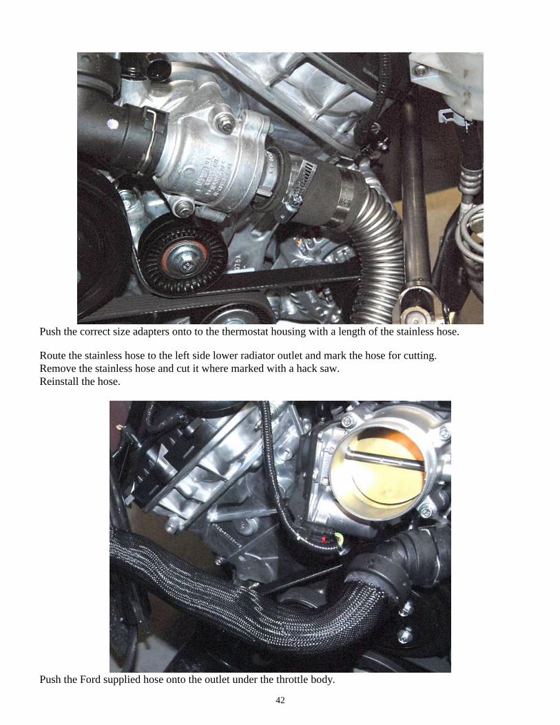
Push the correct size adapters onto to the thermostat housing with a length of the stainless hose.
Route the stainless hose to the left side lower radiator outlet and mark the hose for cutting.
Remove the stainless hose and cut it where marked with a hack saw.
Reinstall the hose.
Push the Ford supplied hose onto the outlet under the throttle body.

43
Decide where you would like to change to the stainless hose and cut the webbing off the hose using wire
cutters.
Cut the hose using a razor knife.
Push the stainless hose into the end of the rubber hose and run the hose to the right side upper radiator inlet.

44
Push and hose clamp the small coolant barb behind the ¾” coolant tubes.
Heater core bypass hose
Push the bypass caps onto the lower tube to the left of the throttle body and hose clamp it.
If running a heater or A/C, do not push the spacer into the tube in the next step.

45
If running a heater or A/C, this is the tube that the heater core would get plumbed into.
Assemble the right side of the heater bypass hose, insert the 0.50” aluminum spacer into the 5/8” heater hose
followed by a hose clamp then push one of the 90° plastic coolant hose adapters.
Tighten the hose clamp using a 5/16” socket and ratchet.
Push the hose onto the top of the tube to the left of the throttle body.
Push the other adapter onto the tube on the right side of the intake then measure and cut the 5/8” heater hose
so that it will connect to the adapter and route where desired.
46
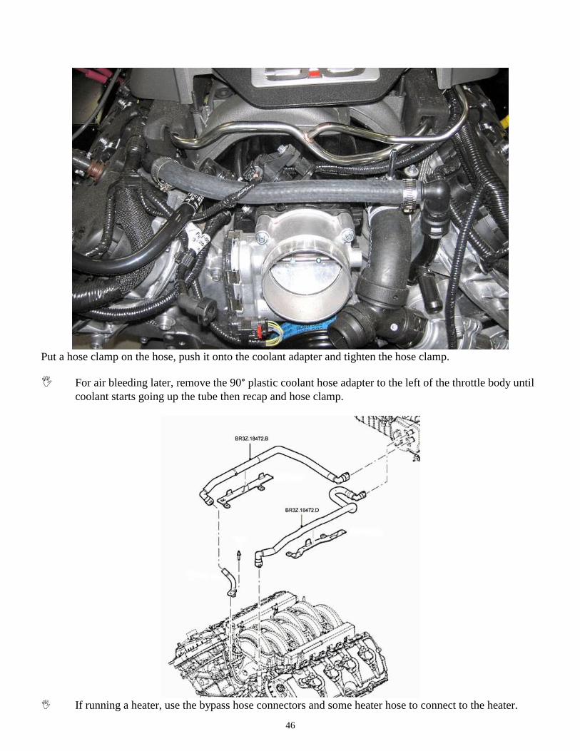
Put a hose clamp on the hose, push it onto the coolant adapter and tighten the hose clamp.
For air bleeding later, remove the 90° plastic coolant hose adapter to the left of the throttle body until
coolant starts going up the tube then recap and hose clamp.
If running a heater, use the bypass hose connectors and some heater hose to connect to the heater.

47
Air Intake
Mass Air Meter
Mass air meter, silicone hoses, intake tubes, air filter
T-20 Torx driver, Flat head screwdriver, Philips head screwdriver, sensor safe RTV silicone
There are two different ways to do this Spectre or Treadstone
Unscrew the mass air sensor from the Ford intake using a T-20 Torx driver

48
Remove the sensor and note the direction of the curved part of the sensor.
Spectre assembly
Install the rubber ring into the intake mount.

49
Insert the sensor into the mount to determine which way around it needs to go so the sensor mount holes will
line up and the sensor will mount the correct way.
Attach the mount to the intake tube using the long screws so that the flat side of the sensor will face the
“Spectre” writing.

50
Install the sensor on the mount using the short screws so the flat side of the sensor will face the “Spectre”
writing.
Run a bead of Sensor safe RTV silicone around the flange of the large plastic reducer.

51
Slide the Mass Air Meter tube flat sensor side first (Spectre writing) down onto the plastic reducer.
Wipe any excess RTV off the tube.
Turn the mass air meter over so the Reducer is on the top and let the RTV dry overnight.

52
Intake tube
Spectre MAF Sensor
Slide the Mass Air Meter tube flat sensor side first (Spectre writing) into the air filter.

53
Adjust the Mass air meter so that the mass air plug is on the far side as the Ford Racing instructions
recommend.
Tighten the hose clamp.
Connect the elbow tube to the mass air meter using the silicone connector; only tighten one of the hose
clamps right now.
Attach the silicone reducer to the tube elbow.

54
Push the intake tube onto the throttle body and position the air filter under the hood hinge.
Tighten the hose clamps.
Treadstone MAF Sensor
Make sure the Mass Air meter is pointed in the correct direction.

55
Push the FFR filter onto the Mass Air meter making sure that the meter is facing the correct direction.
Slide hose clamps onto the 90° Silicone hose.
Test fit the 90° Silicone hose on the mass air meter and the throttle body.

56
Adjust the Mass air meter so that the mass air plug is on the far side as the Ford Performance instructions
recommend.
Tighten the hose clamps
Push the mass air plug onto the mass air meter.
Vacuum ports and PCV vent
Flat head screwdriver, razor knife, WD40
Vacuum plugs, PCV lines, ½” rubber hose, T connector

57
Block off the vacuum ports and fuel evaporator intake tube just behind the throttle body.
Valve cover hoses
If not already done, connect the right side stock PCV hose from the valve cover to behind the throttle body.

58
Attach the fitting to the left side valve cover.
Attach the other end of hose to the intake hose.

59
CMVV Vacuum hose
Attach the CMVV vacuum connector to the bottom fitting on the intake hose.
Clutch position switch
Ford Performance bottom travel switch, coyote clutch switch components.
½”, 9/16” wrench, ½”socket, Ratchet, 3/16”, 5/16” hex keys.
The install is shown outside the footbox for better pictures.
Remove the clutch cable from the quadrant.

60
On the clutch pedal, remove the last 1/8” clutch quadrant end plate and replace it with the stainless bottom
switch clutch quadrant plate.
Tighten the locknuts.

61
Attach the Bottom travel (gray plunger) clutch switch to the bottom travel switch mount as shown.
Remove the bolts holding the left side of the pedal box to the mount bracket.
Insert the new 5/16” x 1.25” bolts through the bottom travel switch mount then through the pedal box bracket
and pedal box.

62
Snug the bolts up with a ½” wrench and socket so the bottom travel switch bracket can still move.
Reattach the clutch cable to the quadrant.
Have someone push the clutch pedal all the way in then slide the bottom travel switch mount so that the
bottom travel switch is pressed in all the way against the quadrant plate. Hold the switch mount so that it

63
does not move and let the clutch out then tighten the pedalbox mount screws with a ½” wrench and socket
making sure the switch mount does not move.
Check the throw of the clutch pedal again carefully. The switch should get pressed in all the way but should
not get pushed hard enough to stress/move the body of the switch.
Wiring
Computer mounting
Aluminum computer mounting bracket, 3/16” rivets
Drill, ¼” driver bit, 3/16” drill bit, rivet tool, ½” wrench, ratchet, ½” socket.
Locate the aluminum computer bracket so that it spans between the upper and lower ¾” tubes that go down
to the front suspension on the right side of the chassis and the rear bottom computer hole lines up with the
front of the right footbox.
Drill and rivet the bracket to the frame using the 3/16” rivets provided.
Attach the computer to the bracket using the 5/16”x 1.25” bolts and nuts provided along with a ½” wrench,
ratchet, ½” socket.
Harness install
Use the diagram at the beginning of these instructions for general routing and component location.
Lay the Control pack harness out on the chassis.

64
Use a 2.00” hole saw to cut a hole in the firewall just to the right of the dash support tube with the center
1.50” up from the 2” x 2” tube.
From the engine bay, push the harness leg with the grommet on through the firewall into the cockpit.

65
In the cockpit, run the wires across to the driver’s footbox.
Connect the Accelerator pedal lead (APPS) to the pedal.

66
Connect the clutch pedal travel switch leads to the correct switches.
16-way Pigtail
Connect the 16 way pigtail plug to the harness.

67
Engine bay
Run the wires to the top of the right footbox. The other holes shown are: Right: rear and sending unit
harnesses. Middle: Alternator and starter harnesses.
Locate the fuse panel mount (logo on it) and align the front edge with the kink in the right footbox.

68
Drill 3/16” holes through the footbox and use three of the 3/16” rivets to attach it to the footbox.
Attach the fuse panel to the mounting bracket using a 5/32” hex key, 7/16” wrench, ¼” washer head screws and
locknuts.
Connect the Engine harness plug and the Control pack plugs to the computer.
69
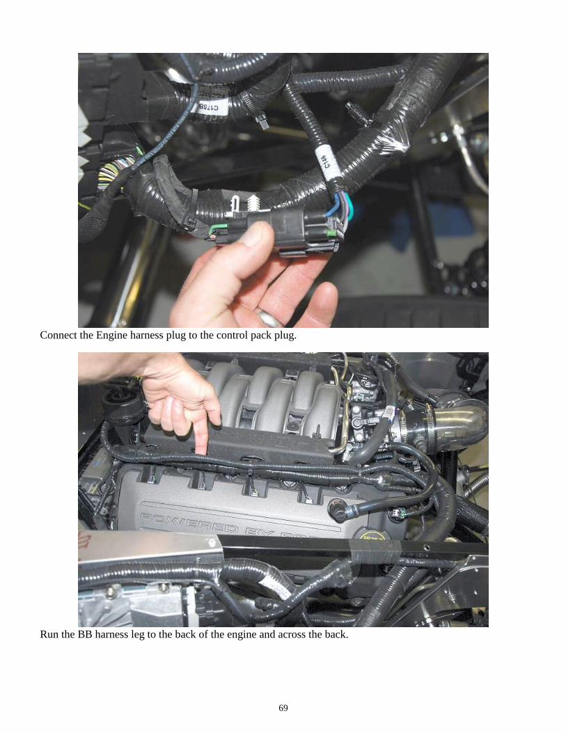
Connect the Engine harness plug to the control pack plug.
Run the BB harness leg to the back of the engine and across the back.

70
Run the BB harness leg back to the front of the engine on the left side.
Mass Air Meter
Plug the mass air meter connector into the mass air meter.
71
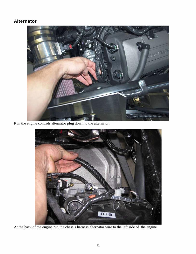
Alternator
Run the engine controls alternator plug down to the alternator.
At the back of the engine run the chassis harness alternator wire to the left side of the engine.

72
Run the chassis harness wires under the engine mount to keep them away from the header.
Attach the chassis harness alternator red wire to the post on the alternator.

73
Attach the engine harness alternator plug to the alternator.
Intercooler wire
Cut the white/red Intercooler pump wire as far back in the harness as you can. It is not needed or used.

74
Radiator Cooling Fan
It is best to let the engine control the radiator fan. If you do not want to do this, do not use the control
pack wires and remove the correct radiator fan fuse from the black box.
From the computer area, run the harness with the orange fan wire forward to the fan and connect to the blue
fan wire.
Ground the black fan wire.
Fuel Pump
The fuel pump wire is in the Ford Performance 16 pin connector.
This set-up allows the engine computer to control the fuel pump instead of the chassis harness but
still uses the fuel inertia cut-off switch.
Route the Coyote harness fuel pump green wire to the back of the chassis harness fuse panel.

75
On the chassis harness, cut the small tan jumper wire close to connector that it jumpers from and connect the
fuel pump wire from the EFI harness onto the chassis harness wire. This will use the EFI computer to turn
the relay on/off.
The Inertia switch grounds the relay so this wiring still uses the inertia switch.
Solder and tape the green wire and Fuel pump relay wires together.
Make sure the wires and harness are out of the way of the steering shaft.

76
Battery power
Mount the inline fuse near the fuse panel using 3/16” rivets then run a battery cable from one side of the inline
fuse to the fuse panel stud.
From the other inline fuse stud run a battery cable to the starter battery cable or to a battery cut-off switch.

77
Start power
Soldering iron, wire cutters/strippers, electrical tape
Locate the EFI/crank and coil wires in the chassis harness.
Attach a ring connector to the black ground wire and ground it to the chassis.

78
Attach the blue starter wire to the blue EFI wire in the harness.
Attach the green ignition trigger wire to the orange EFI wire in the harness.
No other wires are used from the 16 way connector.

79
We use the PCM engine starting directions in the Ford Performance instructions. This uses the
engine harness starting wire to engage the starter.
Find the clutch safty switch wires in the left footbox.
If a neutral safety switch is not going to be used, cut one of the two blue chassis harness wires slightly shorter
than the other so the ends do not touch and electrical tape the end .

80
In the chassis harness on the starter wires leg, cut the blue starter wire end off.
Pull the loom back further down the leg then pull the blue wire out so it does not stick out for the harness and
cut it off.

81
Electrical tape the end to the other wires.
Tach
Soldering iron, wire cutters/strippers, electrical tape.
There is no tach wire in the engine harness. The tach will need to get connected to a coil wire as
shown in the gauge instructions according to the Type #3 Coil on plug description.

82
Run the sending unit harness along the lefttop side of the engine.
At the #4 cylinder, pull the chassis harness tach wire (purple) out of the harness and remove the tape
covering the coil plug wires.

83
Use a razor knife and wire strippers to remove a short section of the wire insulation on the blue/red wire.
Solder the tach wire to the blue/red wire.

84
Wrap the connection in electrical tape.
Re-wrap the coil plug wires.

85
Oil Pressure and Water temp sensors
Continue the sending unit harness to the front of the engine.
Use some of the kit ¾” loom to cover a couple of the smaller looms to declutter the wiring.
Run the wires down the front of the engine to the sending units.

86
Attach the gauge sensor wires to the correct sensor.
OBD 2 Port
Locate the OBD 2 port on the 2”x 2” tube to the right of the steering wheel.

87
Use some of the aluminum panel #6 screws to attach the OBD 2 plug to the frame.
Clutch cable
Attach the clutch cable to the quadrant and to the clutch fork.

88
Exhaust
15mm, 17mm sockets, 15mm wrench
Coyote headers, straight pipes
Insert and tighten all of the bolts by hand before tightening any with a wrench.
Attach the headers to the engine.
O2 Harness
18mm wrench.
The left and right side O2 sensor wires are different lengths, the long one is for the right side.
Screw the O2 sensors into the exhaust.

89
Attach the right O2 sensor to the connector at the back of the head.
Connect the left O2 sensor to the connector down near the engine mount
Starting the engine
Oil, Coolant

90
If not already done, fill the engine with 8 quarts of the correct oil.
If not already done, fill the engine with coolant through an inline filler or radiator cap. To help remove air
from the system, remove the top cap until coolant starts going up the tube then recap and hose clamp.
Fill the coolant overflow container.
Set the Fuel pressure regulator to the correct pressure as described in the Ford Racing engine control
instructions.
Start the engine and allow the engine to get up to 195°F- 200°F then allow to cool completely, it will suck
coolant from the overflow.
Cooling fan is switched on at 195°F, turns off at 190°F. This is based on inferred engine coolant
temperature. Engine coolant temperature is inferred from the cylinder head temperature. Inferred
coolant temperature may not be the same as actual coolant temperature.
Once cool, check the radiator/inline filler neck and coolant overflow container. Top up with coolant if
necessary.