ROADSIDE DITCH AND SHOULDER WATER QUALITY ENHANCEMENT PLAN - kitsapgov.com€¦ · Roadside Ditch...
96
ROADSIDE DITCH AND SHOULDER WATER QUALITY ENHANCEMENT PLAN Kitsap County, Washington DECEMBER 2012
Transcript of ROADSIDE DITCH AND SHOULDER WATER QUALITY ENHANCEMENT PLAN - kitsapgov.com€¦ · Roadside Ditch...

ROADSIDE DITCH AND SHOULDER WATER QUALITY ENHANCEMENT PLAN Kitsap County, Washington
DECEMBER 2012


Table of Contents
Kitsap County i Roadside Ditch and Shoulder Water Quality Enhancement Plan otak
Chapter 1—Introduction 1.1 Background .............................................................................................................................. 1 1.2 How to Use this Plan ............................................................................................................. 3 Chapter 2—Water Quality Enhancement 2.1 Treatment Mechanisms ......................................................................................................... 6 2.2 Key Components to Enhance Water Quality ..................................................................... 6 Chapter 3—Enhancement Plan 3.1 Identification of Priority Areas and Field Inspections .................................................... 11 3.2 Enhancement Types ............................................................................................................. 13
3.2.1 Shoreline Road Cross-Culvert ...................................................................................... 13 3.2.2 Shoreline Road Water Quality Ditch .......................................................................... 14 3.2.3 Rural Roadside Ditch Water Quality Enhancement ................................................. 14 3.2.4 Urban Roadway Water Quality Treatment ................................................................ 15 3.2.5 Fill-slope Embankment Water Quality Treatment ................................................... 16 3.2.6 Bridge or Culvert Stream Crossing.............................................................................. 17
3.3 Cross Sections ....................................................................................................................... 17 3.4 Slope ....................................................................................................................................... 23
3.4.1 Ditch Slope ..................................................................................................................... 23 3.4.2 Side Slope ........................................................................................................................ 24
3.5 Structure ................................................................................................................................. 26 3.5.1 Check Dam ..................................................................................................................... 26 3.5.2 Catchbasin at Cross-Culvert ......................................................................................... 30 3.5.3 Treatment Structures ..................................................................................................... 31 3.5.4 Flow Spreaders / Dispersion ....................................................................................... 32 3.5.5 Permeable Pavement Shoulder .................................................................................... 35
3.6 Decision Flow Chart ............................................................................................................ 36 3.7 Plantings ................................................................................................................................. 43
3.7.1 Ditch and Embankment Planting ................................................................................ 43 3.7.2 Steep Side Slope Planting.............................................................................................. 45
3.8 Conceptual Drawings ........................................................................................................... 46 3.8.1 Enhanced Cross Sections ............................................................................................. 46 3.8.2 Enhanced Cross Section 1-6 ........................................................................................ 49 3.8.3 Enhanced Embankment Fill Slope ............................................................................. 50
3.9 Example Enhancement Project .......................................................................................... 51 Chapter 4—Construction Considerations 4.1 Construction Timing ............................................................................................................ 61 4.2 Preparation of Ditch ............................................................................................................ 61
4.2.1 Soil Excavation ............................................................................................................... 61

Table of Contents
Kitsap County ii Roadside Ditch and Shoulder Water Quality Enhancement Plan otak
4.2.2 Bioretention Soil ............................................................................................................ 61 4.3 Sediment/Erosion Control ................................................................................................. 62
4.3.1 During Construction ..................................................................................................... 62 4.3.2 Suggested Erosion Control BMPs .............................................................................. 62 4.3.3 Post Construction .......................................................................................................... 69
4.4 Planting .................................................................................................................................. 69 4.4.1 Installation Timing ........................................................................................................ 69 4.4.2 Mulch............................................................................................................................... 69
4.5 Construction Methods ......................................................................................................... 70 4.5.1 Bioretention Facilities ................................................................................................... 70 4.5.2 Embankment Fill Slope ................................................................................................ 70
Chapter 5—Maintenance Considerations 5.1 Introduction .......................................................................................................................... 73 5.2 Inspection Considerations .................................................................................................. 73 5.3 Water Quality-Enhanced Ditch/Shoulder Maintenance Considerations .................... 74
5.3.1 Routine Maintenance Considerations ......................................................................... 75 5.3.2 Repair Considerations ................................................................................................... 75
References

Table of Contents
Kitsap County iii Roadside Ditch and Shoulder Water Quality Enhancement Plan otak
Tables Table 3.4.1a Check Dam Type by Slope Percentage Table 3.7.1.a Bioswale Seed Mix Table 4.3.2.a Erosion Control BMPs Table 5.2.A Inspection Considerations
Figures
Figure 3.4.2.1a. Vegetated Retaining Wall System Figure 3.4.2.3 Reinforced gabion wall Figure 3.5.1a Check dam structure (Hard or Cascade style) Figure 3.5.1b Rock Check Dam Figure 3.5.1c Check dam structure (soft) Figure 3.5.1d Check dam structure (soft) Figure 3.5.1e Check Dam Spacing Figure 3.5.2a Catch basin with birdcage inlet at Cross Culvert (optional) Figure 3.5.3a—Bioretention Planter Box Figure 3.5.3b—Proprietary Urban Treatment System Figure 3.5.4a—Dispersal Trench Figure 3.5.4b—Alternative Dispersal Trench Figure 3.5.4c—Diffuser Tee Figure 3.5.5a: Typical Permeable Pavement Surface Section Figure 3.8.3a BMP T9.4 Compost Amended Filter Strip.
Appendices
Appendix A—Literature Review Appendix B—Kitsap SSWM Standard Bioretention and Green Streets Plant List


Chapter 1—Introduction
Kitsap County 1 Roadside Ditch and Shoulder Water Quality Enhancement Plan otak
Kitsap County is committed to preserving and protecting the water quality in our local streams, lakes, wetlands, and marine waters by providing enhancements in the roadside ditches, road shoulders and right-of-way (ROW) areas to remove pollutants from the stormwater, minimize local flooding, and reduce road runoff volumes and storm flows. Many of the roadside ditches are currently well vegetated with a layer of absorbent soil duff lining the ditches and embankments. These areas should be preserved as much as possible because they are providing a significant amount of water quality treatment in this condition (Elfering and Biesboer, 2003). However, ditches that do not currently have good vegetative cover, ditches with poor soils, or ditches that are stripped of the vegetative cover can be enhanced to promote treatment of the storm runoff prior to discharge into the receiving waterbody.
1.1 Background The objective of this manual is to provide guidance and recommendations for retrofit measures that will promote water quality treatment and pollutant removal from stormwater runoff from county-owned roads and ROW areas. Runoff from roadways may contain oil, grease, and heavy metals such as lead, copper, and zinc. Many of the pollutants in roadway runoff are attributed to motor vehicle operation (Elfering and Biesboer, 2003). The wearing of brake linings, bearings, engine crankshafts, and tires results in the deposition of particles containing metals on the roadway surface. The dripping of oil and other engine fluids are washed off the road surface. Soils, sediments and fine dusts are tracked onto the roadway and washed off with the rain. Litter, organic debris, and other materials are also deposited alongside the roadway.
Roadside ditch.
Vegetated ditch

Chapter 1—Introduction
Kitsap County 2 Roadside Ditch and Shoulder Water Quality Enhancement Plan otak
Transportation projects, which tend to be linear in nature, may encompass multiple drainage basins and impact multiple receiving waters. While the runoff discharged from highways and other parts of the transportation infrastructure represents only a portion of the runoff affecting nearby water bodies, it contributes to the cumulative degradation of those waters. The effects of stormwater runoff on receiving waters are typically a function of the proximity of development site discharges to the receiving water body and the size of the receiving water body relative to discharge volumes and flow rates. The impacts of stormwater runoff from County-owned ROW vary widely depending on surrounding land use, climate patterns, soil characteristics, receiving water characteristics, and other local factors, most notably the level of traffic. Average Daily Traffic, or ADT, is often used as a measure of traffic volume. Kitsap County would like to enhance water quality (WQ) treatment within the ROW system at critical drainage areas by modifying the ditches to address WQ treatment using best available science and this plan as a guide. The project provides standard retrofit methodologies based on existing literature (Appendix A).
Kitsap County marker identifying the stream crossing.

Chapter 1—Introduction
Kitsap County 3 Roadside Ditch and Shoulder Water Quality Enhancement Plan otak
1.2 How to Use this Plan Kitsap County road maintenance personnel responsible for retrofitting roadside ditches should follow the planning and construction of ditch types and plantings presented in the decision tree in Chapter 3. In most instances the decision process will be straightforward but the process will prompt the need for construction and maintenance considerations provided in Chapters 4 and 5. Chapter 2 of this plan will introduce the treatment basics of water quality enhancement. In addition, the key components to enhancing water quality will be discussed. Chapter 3 discusses the ditch enhancement types. It also includes the decision tree for selecting the correct ditch type and cross section, and plantings. This chapter also includes conceptual drawings of ditch types and transitions at culvert inlets. Chapter 4 is dedicated to construction considerations for the various enhancement types outlined in Chapter 3. The construction considerations included in the chapter include: construction timing, preparation of ditch, sediment and erosion control, planting methods, irrigation, and construction methods. Chapter 5 provides maintenance considerations for the various ditch enhancement types outlined in Chapter 3. All of the retrofit options will require ongoing periodic maintenance to maintain high-quality, long-term performance of water quality treatment. The ditch enhancements will require less frequent maintenance as the plants become established.

Chapter 1—Introduction
Kitsap County 4 Roadside Ditch and Shoulder Water Quality Enhancement Plan otak
This page intentionally left blank

Chapter 2—Water Quality Enhancement
Kitsap County 5 Roadside Ditch and Shoulder Water Quality Enhancement Plan otak
The main purpose of a conventional roadside ditch is to provide conveyance of the stormwater runoff to a stormwater treatment facility or natural waterbody, mainly to reduce local road flooding. Providing water quality treatment within the ditch to remove pollutants is usually secondary to safely conveying the stormwater without causing localized flooding and causing a safety hazard. Keeping that in mind, ditches and embankments can be modified to provide some water quality treatment to remove or reduce pollutants that are washed off of the roadways. In addition, if infiltration is possible, runoff volume and flow rates can be reduced. Overall, these modifications should result in reduced impacts to the receiving water, while still maintaining their conveyance capacity. Using the principles of bioretention, the concept is to route the stormwater through vegetation and amended soils to promote pollutant removal. Widening of the ditch, amendment of the soils, and providing sufficient vegetation can remove pollutants prior to discharge. In addition, rerouting some flows over embankments with amended soils and vegetation can also promote water quality treatment. The retrofit of an existing ditch or shoulder embankment is usually constrained by the area in the existing right-of-way. Because of these constraints, the retrofit should take advantage of as many of the recognized treatment mechanisms to enhance water quality as possible. The better the key components of the treatment mechanisms are incorporated into the design, the more pollutant removal will be provided. Bioretention Bioretention cells can be used to detain, treat and infiltrate stormwater from numerous sources, including roof runoff, paved area runoff, etc. They may be isolated in a topographical depression with no outflow in certain soil conditions or be linked in multi-basin chains to provide redundant capacity in storm events of varying severity. Bioretention cells consist of an excavated basin backfilled with suitably amended soils (soil specification is very important for good long-term infiltration performance). The soil surface is typically somewhat below grade and slightly concave to allow at least six inches of surface water to pond before overflow. The cell is planted with a range of appropriate plant species. The amended soil absorbs stormwater and allows it to infiltrate to the underlying soil over time. The plants slow surface flows, hold the soils in place, and evapotranspire water from the soil matrix over time. Plant roots and the complex of organisms that live amongst them play a direct role in removing some contaminants from stormwater. They also contribute to the health of the soil matrix which helps maintain infiltration, treatment, and water retention performance over time.
Poorly vegetated ditch

Chapter 2—Water Quality Enhancement
Kitsap County 6 Roadside Ditch and Shoulder Water Quality Enhancement Plan otak
2.1 Treatment Mechanisms Enhancements to the ditches and embankments must be configured to provide treatment as the stormwater is being conveyed. This type of treatment is similar to that of the more conventional biofiltration swales and filter strips. Providing treatment relies on the following mechanisms: • Filtration. The plants will filter sediment and pollutants attached to the sediment as the
water flows through the plants. Dense vegetation will help to filter the pollutants. • Sedimentation. Measures to slow the flow and filter the pollutants will result in the
larger particles settling out. Check dams will create pools of water behind the dams and promote sedimentation.
• Infiltration. The amended soils will hold the stormwater which will either infiltrate or be
taken up by the plants. The first flush of runoff, which typically contains more pollutants, will infiltrate into the amended soils and be treated through infiltration.
• Contact with Organic Matter. The dissolved metals change chemically when they
come into contact with organic matter. Contact with the organic matter promotes the change of the metals from the dissolved state to a form that will settle out and/or is not as toxic to aquatic organisms.
• Flow Attenuation. The amended soils will hold the stormwater and reduce flows. In
addition, check dams and other energy-dissipating methods can be used to slow flow rates and minimize erosion.
The enhancements to the ditches and embankments will promote the treatment mechanisms within the limited areas of the right-of-way. In order to optimize the treatment mechanisms, the following key components should be incorporated to the maximum extent possible. 2.2 Key Components to Enhance Water Quality • Ditch Configuration. Widen and flatten the ditch as much as possible and provide a
mechanism to spread out the flow. Better treatment is achieved when the water flowing through the vegetation is shallow. This may be difficult within a limited ROW.

Chapter 2—Water Quality Enhancement
Kitsap County 7 Roadside Ditch and Shoulder Water Quality Enhancement Plan otak
• Length of Enhancement. Optimally, provide at least 130 feet of enhancement in the
ditch prior to discharge into the receiving waterbody (Elfering and Biesboer, 2003). Maximize the length to the extent circumstances and finances allow, with 130 feet as the minimum length, when possible.
• Soil Amendments. Optimally, provide 18 inches of soil amendment, with coarse
organic compost as the chief element in the amendment. However if this is not possible, provide soil amendments as deep as possible. Existing soils in the ditch may need to be removed to provide for the amended soils. When removing soils from the ditch, do not cut into the toe of a steep adjacent slope.
• Check Dams. Check dams can be provided in ditches with steep slopes. In addition to
slowing the flow and spreading flows across the width of the ditch, the check dam will provide for an area to pool water and promote infiltration. An example that incorporates check dams into the enhancement design is shown below.
Check dam spacing
Optimal wide ditch configuration

Chapter 2—Water Quality Enhancement
Kitsap County 8 Roadside Ditch and Shoulder Water Quality Enhancement Plan otak
• Plant Selection. Choose plants that are herbaceous and not woody. The dense herbaceous leaves will slow the water movement, promote sedimentation, and help filter pollutants. Tall shrubs and trees are not recommended due to sighting safety concerns.
• Flow Dispersion. Spread the flow as much as possible, within a ditch or over an
embankment. Channelized flow can cause erosion and gullies. Spreading the flow will put more water in contact with the vegetation and soil amendments and will promote treatment.
• Steep Slopes. Avoid discharging water over a steep slope at bridge crossings and step
culvert crossings. If possible, reroute flows to disperse the stormwater through vegetation. If necessary, provide piping to the stream to prevent further erosion.
Example of a roadside ditch before and after enhancement. This enhancement utilized check
dams and rock side slope structures. (Source: Seattle Public Utilities)

Chapter 2—Water Quality Enhancement
Kitsap County 9 Roadside Ditch and Shoulder Water Quality Enhancement Plan otak
Example of a roadside ditch enhancement before and after the amended soils and vegetation
were placed. (Source: Seattle Public Utilities)

Chapter 2—Water Quality Enhancement
Kitsap County 10 Roadside Ditch and Shoulder Water Quality Enhancement Plan otak
This page intentionally left blank

Chapter 3—Enhancement Plan
Kitsap County 11 Roadside Ditch and Shoulder Water Quality Enhancement Plan otak
Chapter 3 of the Roadside Ditch and Shoulder Water Quality Enhancement Plan introduces the development of the ditch enhancement types and the necessary steps to construct such a plan. This chapter introduces the decision tree to assist personnel responsible in selecting the appropriate enhancement strategy for roadside ditches. This chapter also provides conceptual drawings of the enhancements. Lastly, plant selection discusses the appropriate planting for each ditch type based on conditions found in the ditch. 3.1 Identification of Priority Areas and Field Inspections Kitsap County covers almost 400 square miles and includes thousands of miles of maintained roads and associated roadside ditches. In order to make the water quality enhancements most effective, critical areas were identified that would benefit the most from water quality enhancement retrofitting. Enhancements of the ditches/shoulders just prior to discharge to the receiving water provides the opportunity to remove pollutants associated with roadway runoff and reduce the impacts of those pollutants to the receiving waters. Two types of critical areas were identified for this plan due to their proximity to receiving water bodies: • Roadways crossing streams via culverts or bridges. • Roadways adjacent to salt and freshwater shoreline with associated culverts discharging
stormwater directly to the waterbody. In addition, roads with high Average Daily Trips (ADT) were prioritized over lower ADT roads. ADT was used as a surrogate for pollution generation potential based on the general correlation of traffic density and pollutant levels (Elfering and Biesboer, 2003). Initial field inspections were conducted at road stream crossings and roads adjacent to the shoreline. Based on the field inspections, six retrofit project types were identified: 1. Shoreline Road Cross-Culvert 2. Shoreline Water Quality Ditch Enhancement 3. Urban Roadway Water Quality Treatment 4. Fill-slope Embankment Water Quality Treatment 5. Bridge or Culvert Stream Crossing with Ditch Enhancement 6. Rural Roadside Ditch Water Quality Enhancement
Enhanced ditch (Source: Seattle Public Utilities)

Chapter 3—Enhancement Plan
Kitsap County 12 Roadside Ditch and Shoulder Water Quality Enhancement Plan otak
Section 3.2 describes and illustrates the six retrofit project types and presents optional arrangements. Section 3.3 then diagrams and describes ditch cross-sectional patterns found in the field survey and points out various possible enhancements appropriate for each cross section. Section 3.4 covers longitudinal and side slopes seen around the County, when they need some adjustment to help meet water quality objectives, and how that adjustment can be made when needed. Section 3.5 follows with descriptions and specifications of structures often needed in the ditch and shoulder enhancement projects, including check dams, catch basins, treatment structures (e.g., planter boxes, treatment cartridges), and flow spreading and dispersion devices. Section 3.6 presents decision flow charts matching recommended enhancement strategies and structures to each combination of project type, cross section, and slope condition for optimal water quality benefits. Once the user has identified the type and existing cross section and slopes, the charts provide guidance in selecting and designing the elements of the retrofit plan. Section 3.7 follows with vegetation selection recommendations. Section 3.8 shows sample cross sections bringing all the elements together, while Section 3.9 completes the chapter with example ditch enhancement projects.

Chapter 3—Enhancement Plan
Kitsap County 13 Roadside Ditch and Shoulder Water Quality Enhancement Plan otak
3.2 Enhancement Types Following describes each of the six enhancement types, gives examples of where each type may be located within Kitsap County, and enhancement options. 3.2.1 Shoreline Road Cross-Culvert
Shoreline Road Cross-Culvert
The shoreline cross culverts are located at roads that are adjacent to the shoreline. Typically the road runoff is collected in a ditch that is on the opposite side of the road from the shoreline. Runoff flows through the ditch and is discharged to the receiving water through cross-culverts under the road. These cross-culverts usually convey runoff from both ditch directions. There may or may not be a structure at the inlet to the culvert; the transition from the ditch to the culvert is often a small rocked sump area without a catch basin. Examples of locations of the shoreline culvert crossing enhancement types: • Beach Drive • Lemolo Shore Drive Options for enhancement of this type include: • Bioretention retrofit of the ditches approaching the cross
culvert. • Installation of a tree-box filter in more urban settings or
where roadside ditches have been piped. • Installation of a structure ( e.g. Type II catch basin) with a
sump and internal water quality treatment component. Special considerations for shoreline locations: Use shorter vegetation to preserve shoreline views. Check dams or weirs may be required steeper ditch lines. Design Details: Conceptual Drawings are in Section 3.8.

Chapter 3—Enhancement Plan
Kitsap County 14 Roadside Ditch and Shoulder Water Quality Enhancement Plan otak
3.2.2 Shoreline Road Water Quality Ditch
Shoreline Road Water Quality Ditch
The shoreline road water quality ditch is similar to the shoreline road cross-culvert type, except that the ditch is on the same side of the road and there are no cross-culverts. Examples of locations of the shoreline road ditch include: • Beach Drive • Lemolo Shore Drive Options for enhancement of this type include: • Bioretention retrofit of the ditches. Special considerations for shoreline locations: Use shorter vegetation to preserve shoreline views. Design Details: Conceptual Drawings are in Section 3.8.
3.2.3 Rural Roadside Ditch Water Quality Enhancement
Rural Roadside Ditch Water Quality Enhancement
The rural roadside ditch enhancement is targeted at ditches along rural roads. The ditch configuration may be constrained by narrow right-of-way and steep side slopes to the ditch. Examples or the rural roadside ditch water quality enhancement include: • Multiple areas throughout Kitsap County Options for enhancements include: • Bioretention within the ditch; use check dams or rocked
ditches on steep slopes. • Dispersion to areas adjacent to the ditch. • Infiltration trench (narrow ROW). Design Details: Conceptual Drawings are in Section 3.8.

Chapter 3—Enhancement Plan
Kitsap County 15 Roadside Ditch and Shoulder Water Quality Enhancement Plan otak
3.2.4 Urban Roadway Water Quality Treatment
Urban Roadway Water Quality Treatment
The urban roadway water quality treatment type targeted at roadside ditches in the more urban areas. Curbs, gutters and sidewalks may or may not currently be present. This enhancement type would incorporate urban options for treatment. In situations where soils are suitable, infiltration may be the preferred option. Examples of locations for urban roadway water quality treatment include: • Multiple areas throughout Kitsap County Options for enhancement of this type include: • Sidewalk, shoulder, walkway, or bus stop conversion of a
ditch to closed system with boxed treatment (tree box filters, modular sand filters, or infiltration trench).
• Installation of a boxed treatment (tree box filter, modular sand filter, or infiltration trench) within an urban piped system.
Design Details: Conceptual Drawings are in Section 3.8.

Chapter 3—Enhancement Plan
Kitsap County 16 Roadside Ditch and Shoulder Water Quality Enhancement Plan otak
3.2.5 Fill-slope Embankment Water Quality Treatment
Fill-slope Embankment Water Quality Treatment
The fill-slope embankment water quality treatment option would provide treatment over the roadside embankment that has been soil amended with compost. Stormwater will be dispersed over a vegetated slope to provide treatment. This enhancement is similar to a soil amended vegetated filter strip. This enhancement could also disperse runoff that is currently collected in a conveyance system and spread it over the soil-amended vegetated slope. Examples of locations for fill slope embankment water quality treatment include: • Multiple areas throughout Kitsap County Options for enhancement of this type include: • Flow spread over embankment with soil amendments
(compost). • Flow collected in conveyance and dispersed on
embankment (vial level spreader). Special considerations for this treatment type: This treatment type requires structural considerations to the embankment. The use of terracing, wattles and other methods may be considered. Design Details: Conceptual Drawings are in Section 3.8.

Chapter 3—Enhancement Plan
Kitsap County 17 Roadside Ditch and Shoulder Water Quality Enhancement Plan otak
3.2.6 Bridge or Culvert Stream Crossing
Bridge or Culvert Stream Crossing
The bridge and culvert stream crossing include roadside ditchesthat discharge at stream culverts or bridges. Typically there is a steep drop from the outlet of the roadside ditch to the receiving water, although ditches approaching the crossing can be both steep and flat. These areas are critical for water quality because there is typically a direct discharge to a creek with little or no formal water quality treatment Examples of locations for the bridge or culvert stream crossing include: • Multiple areas throughout Kitsap County Options for enhancement of this type include: • Diverting and dispersal of the runoff over an embankment,
similar to the fill slope embankment. • Routing and/or dispersion of the ditch outlet into
vegetated areas adjacent to the stream channel. • Providing bioretention in the ditches and routing the flow
via energy dissipation into the stream. • Use the rocked ditch (with soil amendments) for ditches
with longitudinal slopes between 2½ and 15 %. Design Details: Conceptual Drawings are in Section 3.8.
3.3 Cross Sections Field inspections of ditches and right of way areas in Kitsap County were conducted. Physical attributes of the ditches/shoulders were collected, including photo documentation, documenting the general condition of the ditch, measurement of ditch geometry, and vegetation characterization. The information collected from inspected sites was compiled and used to identify the nine cross-sectional existing conditions. The ditch types and cross sections will assist County staff in developing enhancement strategies, based on the decision flow chart below, that will identify the type of enhancement that works best under certain ditch/shoulder conditions.

Chapter 3—Enhancement Plan
Kitsap County 18 Roadside Ditch and Shoulder Water Quality Enhancement Plan otak
Cross Section 1
Cross section 1 is characterized by narrow “V” shaped ditch bottom with widths approximately 6” to 12”, narrow shoulders and a steep and high back slope. Usually found on the cut slope of rural roads where longitudinal slopes range from moderate to steep. Usually the ditch is dry but a base flow might occur when ground water seeps are present.
Widen as much as possible Use side slope enhancements (Section 3.4.2):
• Vegetated retaining wall • Rock side slope • Reinforced gabion
See Section 3.8 for conceptual drawings
Cross Section 2
Cross section 2 is characterized by wide undefined ditch bottom width (approximately 6’ to 15’), wider shoulders and a steep and high fore-slope and little to no back slope. Usually found on the fill slope of rural roads where longitudinal slopes range from flat to moderate.
Use embankment for treatment. Use ammended soils and plant embankment; sheetflow road runoff over embankment See Section 3.8 for conceptual drawings

Chapter 3—Enhancement Plan
Kitsap County 19 Roadside Ditch and Shoulder Water Quality Enhancement Plan otak
Cross Section 3
Cross section 3 is characterized by moderate shaped “V” to wider “U” ditch bottom with widths approximately 18” to 36”, wide shoulders and a steep back slope that rises above the height of the roadway but immediately flattens for grading of private property. Usually found on frontage of private property along rural roads where longitudinal slopes range from flat to moderate. The ditch can be dry or with a base flow depending on local groundwater conditions.
Widen if possible Use embankment for treatment. Use ammended soils and plant embankment; sheetflow road runoff over embankment Use side slope enhancements (Section 3.4.2):
• Vegetated retaining wall • Rock side slope
See Section 3.8 for conceptual drawings
Cross Section 4
Cross section 4 is characterized by a lack of a defined ditch bottom and poor condition of the roadside vegetation. Usually found in urban areas where sidewalk improvements haven’t been installed.
Install an urban treatment structure (Section 3.5.3) with sidewalk, curb and gutter See Section 3.8 for conceptual drawings

Chapter 3—Enhancement Plan
Kitsap County 20 Roadside Ditch and Shoulder Water Quality Enhancement Plan otak
Cross Section 5
Cross section 5 is characterized by moderate “V” shaped ditch bottom with widths approximately 18” to 36”, wide shoulders and a steep back slope that rises to the same height of the roadway but immediately flattens for grading of private property. Usually found on frontage of private property along rural roads where longitudinal slopes range from flat to moderate. The ditch can be dry or with a base flow depending on local groundwater conditions.
Widen if possible Use embankment for treatment. Use ammended soils and plant embankment; sheetflow road runoff over embankment See Section 3.8 for conceptual drawings

Chapter 3—Enhancement Plan
Kitsap County 21 Roadside Ditch and Shoulder Water Quality Enhancement Plan otak
Cross Section 6
Cross section 6 is characterized by moderate “U” shaped ditch bottom with steep side slopes and bottom widths approximately 12” to 36”, wide shoulders and a steep back slope that rises to the same height of the roadway but immediately flattens for grading of private property. Usually found on frontage of private property along rural roads where longitudinal slopes range from flat to moderate. The ditch can be dry or with a base flow depending on local groundwater conditions.
Widen if possible Use side slope enhancements (Section 3.4.2):
• Vegetated or engineered retaining wall • Rock side slope
See Section 3.8 for conceptual drawings
Cross Section 7 & 8
Cross sections 7 and 8 are characterized by long and wide fill slope roadway embankments.
Use embankment for treatment. Use ammended soils and plant embankment; sheetflow road runoff over embankment See Section 3.8 for conceptual drawings

Chapter 3—Enhancement Plan
Kitsap County 22 Roadside Ditch and Shoulder Water Quality Enhancement Plan otak
Cross Section 9
Cross section 9 is characterized by a deep inlet to a roadway culvert. The depth of the ditch at this section tends to be deeper than rest of the ditch section upstream of the culvert. The section can be dry or with a base flow depending on local groundwater conditions.
Widen if possible Use side slope enhancements (Section 3.4.2):
• Vegetated retaining wall • Rock side slope
Install a structure (catch basin, etc) if the ditch is deep. See Section 3.8 for conceptual drawings

Chapter 3—Enhancement Plan
Kitsap County 23 Roadside Ditch and Shoulder Water Quality Enhancement Plan otak
3.4 Slope 3.4.1 Ditch Slope The ditch slope refers to the longitudinal slope of the ditch. The steepness of the ditch slope can be either shallow or steep. Shallow Slope A ditch with a shallow slope has a slight gradient. In areas with highly infiltrative soils, these shallow sloped ditches may be well drained. If the soils are not infiltrative, these shallow ditches may be wet with saturated conditions much of the year. Selection of the appropriate plants depends on how infiltrative the soils are underlying these shallow sloped ditches. Steep Slope Ditches with steep slopes may need additional enhancement measures. Table 3.4.1a summarizes the type of check dam that can be used based on the longitudinal slope of the ditch. If the longitudinal slope is steep, approximately 5% to 10%, installation of check dams can help to slow the flow of stormwater and help protect the plants. Installation of the check dam will provide areas for the short-term ponding of stormwater to facilitate infiltration. If check dams are installed, the plants selected will need to be tolerant of wet saturated conditions. Slopes in excess of 10% may require rock lining or other slope protection. The rock lined ditch should also be planted with appropriate plants. In situations of excesses steepness (Slopes over 15% at distances over 20 feet), the cascade check dam configuration may be considered.
Table 3.4.1a Check Dam Type by Slope Percentage
Slope Type of Check Dam
0 to 2.5% No check dam
2.5% to 10% Soft or Rock check dams
10% to 15% Rock lined ditch with hard check dams
>15% Cascade check dam See Section 3.5 Structure for check dam options.

Chapter 3—Enhancement Plan
Kitsap County 24 Roadside Ditch and Shoulder Water Quality Enhancement Plan otak
3.4.2 Side Slope Many of the ditches have steep side slopes and are vulnerable to erosion. Examples of these conditions can be seen in the side slopes cross sections 1 and 3. These steep side slopes should be planted to prevent erosion. See the Section 3.7 for plant recommendations. 3.4.2.1 Reinforced Soil Slope Vegetated reinforced soil stabilization systems (Figure3.4.2.1a) can be used at locations where the side slopes have shown sign of failure and cannot be stabilized by plantings only. These types of systems use porous non-woven geotextile units that retains aggregate fill yet porous enough to support vegetative growth.
Figure 3.4.2.1a. Vegetated Retaining Wall System
Roadside ditch enhancement gravel bottom
and vegetated wall system. (Source: Seattle Public Utilities)
Chapter 3—Enhancement Plan
Kitsap County 25 Roadside Ditch and Shoulder Water Quality Enhancement Plan otak
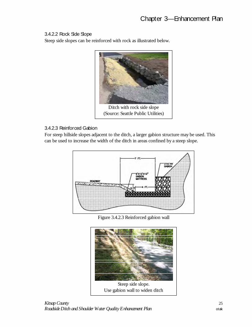
3.4.2.2 Rock Side Slope Steep side slopes can be reinforced with rock as illustrated below.
3.4.2.3 Reinforced Gabion For steep hillside slopes adjacent to the ditch, a larger gabion structure may be used. This can be used to increase the width of the ditch in areas confined by a steep slope.
Figure 3.4.2.3 Reinforced gabion wall
Steep side slope.
Use gabion wall to widen ditch
Ditch with rock side slope
(Source: Seattle Public Utilities)

Chapter 3—Enhancement Plan
Kitsap County 26 Roadside Ditch and Shoulder Water Quality Enhancement Plan otak
3.5 Structure Many of the enhancement projects may require the installation of structures. Types of structures that may be required include: check dams, catch basins, treatment structures (i.e. planter boxes, treatment cartridges), and flow spreaders or dispersion. 3.5.1 Check Dam Construction of small dams across a swale or ditch reduces the velocity of concentrated flow and dissipates energy at the check dam. The check dam can be either a hard structure or a soft structure. A hard concrete check dam structure is often used in urban ditches, but can also be used in rural settings where the creation of pools behind the check dams is desirable or where the longitudinal slope of the ditch is greater than fifteen percent. A hard check dam structure should be constructed according the Kitsap County Surface & Stormwater Management (KCSWWM) precast concrete weir detail (Figure 3.5.1a).
Cascading configuration with check dams (Source: Seattle
Public Utilities)

Chapter 3—Enhancement Plan
Kitsap County 27 Roadside Ditch and Shoulder Water Quality Enhancement Plan otak
Figure 3.5.1a Check dam structure (Hard or Cascade style) A rock check dam can be used when the longitudinal slope of the ditch is between five and ten percent. Figure 3.5.1b illustrates a rock check dam.
Figure 3.5.1b Rock Check Dam
A softer check dam is created by using material such as straw bales, coir logs, coir nettings, and straw wattles. These softer check dams may be more visually pleasing in rural ditches. These softer check dams can be used in steep slope ditches to reduce stormwater velocity and protect the plants. However, the soft check dams are limited in their ability to create a pool for enhanced attenuation and infiltration. Figures 3.5.1c and 3.5.1d show an example of a softer style check dam.

Chapter 3—Enhancement Plan
Kitsap County 28 Roadside Ditch and Shoulder Water Quality Enhancement Plan otak
Figure 3.5.1c Check dam structure (soft)
Placement of the soft check dam in the ditch.

Chapter 3—Enhancement Plan
Kitsap County 29 Roadside Ditch and Shoulder Water Quality Enhancement Plan otak
Figure 3.5.1d Check dam structure (soft)
General construction considerations include: • Location of the check dam should be carefully considered. Check dams should remain as
permanent installations with very minor regrading. They may be left as either spillway, in which case accumulated sediment would be graded and seeded, or as check dams to prevent further sediment from leaving the site.
• Check dams should be placed perpendicular to the flow of water. • The maximum spacing between the dams should be such that the toe of the upstream
dam is at the same elevation as the top of the downstream dam. Figure 3.6.1e below illustrates how to determine the check dam spacing.
• Keep the maximum height at 1 foot at the center of the dam. • Key the weir into the ditch banks and extend it beyond the abutments a minimum of 18
inches to avoid washouts from overflow around the dam. • Check dams may be considered when slopes are greater than 5%. If the ditch bottom is
very wide (greater than 10 feet) and the ditch show no signs of erosion or concentrated flow, then other non check dam configurations may be considered.

Chapter 3—Enhancement Plan
Kitsap County 30 Roadside Ditch and Shoulder Water Quality Enhancement Plan otak
Figure 3.5.1e Check Dam Spacing
3.5.2 Catchbasin at Cross-Culvert A structure may be beneficial at the point that shoreline ditches discharge to the existing culverts under the road. Many of the existing culvert crossings do not currently have catchbasins at this point. Installation of catchbasin structures can provide a mechanism to pool water within the enhanced ditches with the overflow discharging to the culvert. Pooling of the stormwater will promote increased attenuation within the soils and infiltration. Figure 3.5.2a shows how the catchbasin can be installed to provide a pool within the enhanced ditch.
Figure 3.5.2a Catch basin with birdcage inlet at Cross Culvert (optional)

Chapter 3—Enhancement Plan
Kitsap County 31 Roadside Ditch and Shoulder Water Quality Enhancement Plan otak
3.5.3 Treatment Structures Planter Box/Proprietary Treatment System A viable variation of bioretention swale is the bioretention planter box. The planter itself contains the soil and vegetation with an impermeable liner that does not allow the runoff to infiltrate into the native soil. This is an effective Low Impact Development Best Management Practice (BMP) in urban and commercial areas where subsurface conditions
preclude infiltration (high groundwater, contaminated soils, etc.). This is also a good option for urbanizing areas where there are currently ditches. These types of treatment can be incorporated into projects that upgrade the infrastructure to include curb and sidewalk and conveyance pipes.
Examples of enhanced ditches with catch basin structures
(Source: Seattle Public Utilities)
Figure 3.5.3a—Bioretention Planter Box

Chapter 3—Enhancement Plan
Kitsap County 32 Roadside Ditch and Shoulder Water Quality Enhancement Plan otak
3.5.4 Flow Spreaders / Dispersion End of Ditch Structures Engineered dispersion uses existing vegetation and landscaped areas, existing soils or engineered compost-amended soils, and topography to effectively provide runoff treatment. Engineered dispersion is ideal for highways and linear roadways at stream and culvert crossings. The key to effective engineered dispersion is that flows from the impervious area enter the dispersion area as sheet flow. Flow is conveyed from the impervious area via roadside ditch or closed conduit to dispersion BMP that spreads runoff from concentrated flow to sheet flow. Dispersion BMPs can be Flow Dispersion Trench, Alternate Flow Dispersion Trench, Tee Type energy Dissipater or any approved engineered flow spreading BMP.
Figure 3.5.3b—Proprietary Urban Treatment System

Chapter 3—Enhancement Plan
Kitsap County 33 Roadside Ditch and Shoulder Water Quality Enhancement Plan otak
Figures 3.5.4a, 3.5.4b, and 3.5.4c show options for flow spreaders.
Figure 3.5.4a—Dispersal Trench

Chapter 3—Enhancement Plan
Kitsap County 34 Roadside Ditch and Shoulder Water Quality Enhancement Plan otak
Figure 3.5.4c—Diffuser Tee
Figure 3.5.4b—Alternative Dispersal Trench

Chapter 3—Enhancement Plan
Kitsap County 35 Roadside Ditch and Shoulder Water Quality Enhancement Plan otak
3.5.5 Permeable Pavement Shoulder The road shoulder can be adapted to incorporate permeable pavement. Figure 3.5.5a shows a typical permeable pavement surface section. Permeable pavement, including pervious concrete, porous asphalt, and permeable interlocking concrete pavement, can be incorporated into a ditch retrofit design or used by itself. Permeable pavement should be installed consistent with the Kitsap County Low Impact Development (LID) Guidance Manual.
Figure 3.5.5a: Typical Permeable Pavement Surface Section (Source: City of Seattle Stormwater Flow Control and Water Quality Treatment Technical
Requirements Manual) Permeable pavement can reduce stormwater runoff and improve water quality by infiltration of the stormwater. Permeable pavement should not be used in situations where infiltration would compromise the structural stability of the road bed.

Chapter 3—Enhancement Plan
Kitsap County 36 Roadside Ditch and Shoulder Water Quality Enhancement Plan otak
3.6 Decision Flow Chart Following is a decision flow chart for each of the six enhancement types. For each enhancement type, the designer will consider the following criteria: • The cross section of the existing ditch • The slopes of the ditch and the side slope • The need for a structure in the enhancement • Plant selection In addition, the designer must consider the underlying soil and infiltration capacity. Enhancements may not be appropriate in areas where infiltration could compromise the structural integrity of the roadway.
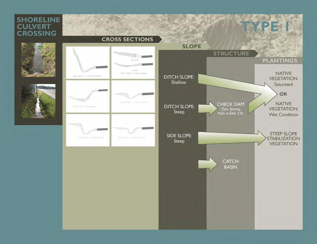

TYPE 2SHORELINE WATER QUALITY DITCH
DITCH SLOPE:Shallow
DITCH SLOPE:Steep
NATIVE VEGETATION:
Saturated
NATIVE VEGETATION: Wet Condition
STEEP SLOPE STABILIZATION VEGETATION
CHECK DAM (Type, Spacing,
Refer to Table 3.X)
SIDE SLOPE:Steep
OR
CROSS SECTIONSSLOPE
STRUCTUREPLANTINGS

URBANROADWAYWQTREATMENT:SUBTYPESTO DITCH
TYPE 3
URBANROADWAYWQTREATMENT:SUBTYPES TO MECHANICALSYSTEM
CROSS SECTIONSSLOPE
STRUCTUREPLANTINGS
CURB & GUTTER PLANTER BOX
FILTERRA
OTHER MECHANICAL SYSTEMS (i.e. StormFilter, BayFilter, Vortex Swirl
Concentrators)(Type, Spacing)
(CONVEYANCE PIPES)
NATIVE VEGETATION
CHECK DAM (Type, Spacing,
Refer to Table 3.X)
DITCH SLOPE:Shallow
DITCH SLOPE:Steep
SIDE SLOPE:Steep
NATIVE VEGETATION:
Saturated
NATIVE VEGETATION: Wet Condition
STEEP SLOPE STABILIZATION VEGETATION
OR
CROSS SECTIONSSLOPE
STRUCTUREPLANTINGS

NATIVEGRASSES
FILL-SLOPEEMBANK-MENT
TYPE 4
DITCH SLOPE:Shallow
DITCH SLOPE:Steep
FLOWSPREADER/DISPERSION
@ TOP OF SLOPE
CROSS SECTIONSSLOPE
STRUCTUREPLANTINGS

TYPE 5CROSS SECTIONS
SLOPESTRUCTURE
PLANTINGS
SLOPEVEGETATION
DISPERSAL TRENCH
ALTERNATE DISPERSAL TRENCH
DISPERSAL TEE-SECTION
BRIDGE ORCULVERTSTREAMCROSSING
ENGINEEREDDISPERSIONAT BRIDGECROSSING

TYPE 6CROSS SECTIONS
SLOPESTRUCTURE
PLANTINGS
DITCH SLOPE:Shallow
DITCH SLOPE:Steep
CHECK DAM (Type, Spacing,
Refer to Table 3.X)
RURALROADSIDEDITCHWATERQUALITYENHANCE-MENT
END OF DITCHSTRUCTURE
DISPERSALTRENCH
ALTERNATEDISPERALTRENCH
DISPERSALTEE-SECTION
NATIVE VEGETATION:
Saturated
NATIVE VEGETATION: Wet Condition
SIDE SLOPE:Steep
OR
STEEP SLOPE STABILIZATION VEGETATION
Chapter 3—Enhancement Plan
Kitsap County 43 Roadside Ditch and Shoulder Water Quality Enhancement Plan otak
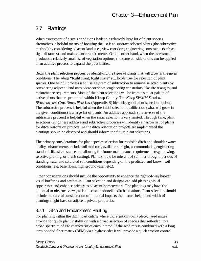
3.7 Plantings When assessment of a site’s conditions leads to a relatively large list of plant species alternatives, a helpful means of focusing the list is to subtract selected plants (the subtractive method) by considering adjacent land uses, view corridors, engineering constraints (such as sight distances), and maintenance requirements. On the other hand, when the assessment produces a relatively small list of vegetation options, the same considerations can be applied in an additive process to expand the possibilities. Begin the plant selection process by identifying the types of plants that will grow in the given conditions. The adage “Right Plant, Right Place” still holds true for selection of plant species. One helpful process is to use a system of subtraction to remove selected plants by considering adjacent land uses, view corridors, engineering constraints, like site triangles, and maintenance requirements. Most of the plant selections will be from a similar palette of native plants that are promoted within Kitsap County. The Kitsap SWMM Standard Bioretention and Green Streets Plant List (Appendix B) identifies good plant selection options. The subtractive process is helpful when the initial selection qualification (what will grow in the given conditions) is a large list of plants. An additive approach (the inverse of the subtractive process) is helpful when the initial selection is very limited. Through time, plant selections using these additive and subtractive processes will identify a narrow list of plants for ditch restoration projects. As the ditch restoration projects are implemented the plantings should be observed and should inform the future plant selections. The primary considerations for plant species selection for roadside ditch and shoulder water quality enhancements include soil moisture, available sunlight, accommodating engineering standards like site distance and allowing for future maintenance requirements (e.g. mowing, selective pruning, or brush cutting). Plants should be tolerant of summer drought, periods of standing water and saturated soil conditions depending on the predicted and known soil conditions (e.g. base flows, high groundwater, etc.). Other considerations should include the opportunity to enhance the right-of-way habitat, visual buffering and aesthetics. Plant selection and designs can add pleasing visual appearance and enhance privacy to adjacent homeowners. The plantings may have the potential to obstruct views, as is the case in shoreline ditch situations. Plant selection should include the careful consideration of potential impacts the mature height and width of plantings might have on adjacent private properties. 3.7.1 Ditch and Embankment Planting For planting within the ditch, particularly where bioretention soil is placed, seed mixes provide for quick plant installation with a broad selection of species that self-adapt to a broad spectrum of site characteristics encountered. If the seed mix is combined with a long term bonded fiber matrix (BFM) via a hydroseeder it will provide a quick erosion control
Chapter 3—Enhancement Plan
Kitsap County 44 Roadside Ditch and Shoulder Water Quality Enhancement Plan otak
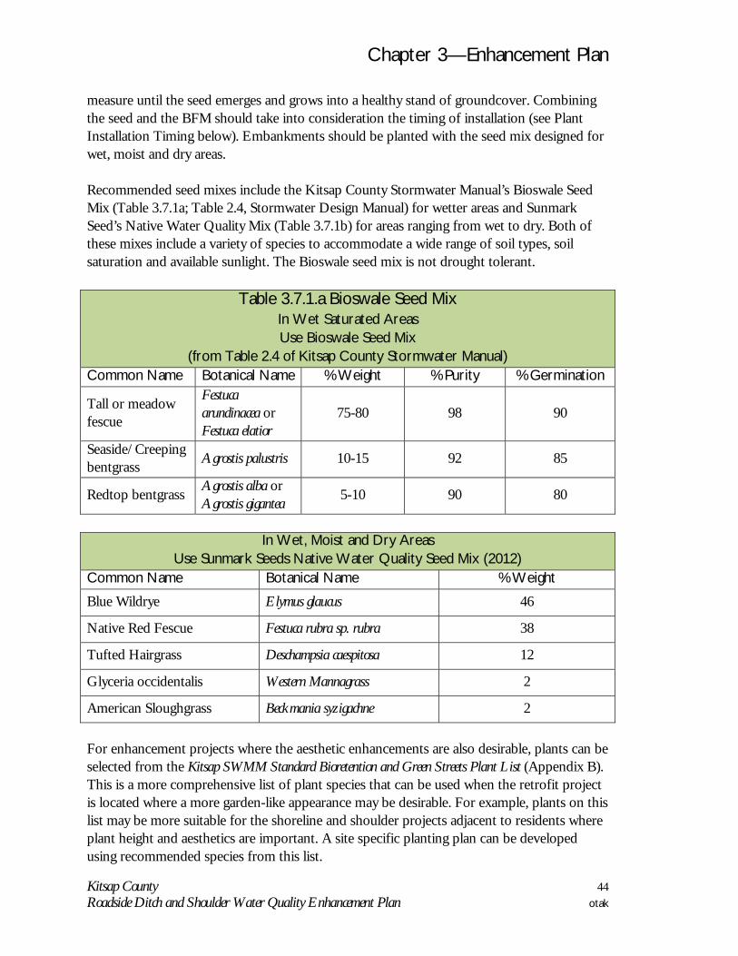
measure until the seed emerges and grows into a healthy stand of groundcover. Combining the seed and the BFM should take into consideration the timing of installation (see Plant Installation Timing below). Embankments should be planted with the seed mix designed for wet, moist and dry areas. Recommended seed mixes include the Kitsap County Stormwater Manual’s Bioswale Seed Mix (Table 3.7.1a; Table 2.4, Stormwater Design Manual) for wetter areas and Sunmark Seed’s Native Water Quality Mix (Table 3.7.1b) for areas ranging from wet to dry. Both of these mixes include a variety of species to accommodate a wide range of soil types, soil saturation and available sunlight. The Bioswale seed mix is not drought tolerant.
Table 3.7.1.a Bioswale Seed Mix In Wet Saturated Areas Use Bioswale Seed Mix
(from Table 2.4 of Kitsap County Stormwater Manual) Common Name Botanical Name % Weight % Purity % Germination
Tall or meadow fescue
Festuca arundinacea or Festuca elatior
75-80 98 90
Seaside/Creeping bentgrass Agrostis palustris 10-15 92 85
Redtop bentgrass Agrostis alba or Agrostis gigantea 5-10 90 80
In Wet, Moist and Dry Areas
Use Sunmark Seeds Native Water Quality Seed Mix (2012) Common Name Botanical Name % Weight
Blue Wildrye Elymus glaucus 46
Native Red Fescue Festuca rubra sp. rubra 38
Tufted Hairgrass Deschampsia caespitosa 12
Glyceria occidentalis Western Mannagrass 2
American Sloughgrass Beckmania syzigachne 2 For enhancement projects where the aesthetic enhancements are also desirable, plants can be selected from the Kitsap SWMM Standard Bioretention and Green Streets Plant List (Appendix B). This is a more comprehensive list of plant species that can be used when the retrofit project is located where a more garden-like appearance may be desirable. For example, plants on this list may be more suitable for the shoreline and shoulder projects adjacent to residents where plant height and aesthetics are important. A site specific planting plan can be developed using recommended species from this list.

Chapter 3—Enhancement Plan
Kitsap County 45 Roadside Ditch and Shoulder Water Quality Enhancement Plan otak
3.7.2 Steep Side Slope Planting Adjacent to the ditch restoration will be different slopes that may require replanting. Refer to the Kitsap SWMM Standard Bioretention and Green Streets Plant List (Appendix B) for a list of pre-approved woody and herbaceous plants detailing moisture zone conditions and mature size. Conceptual drawings (typical cross-sections of ditches) show many types of these slopes. These slopes will tend to be dryer than adjacent areas. Recommendations for replanting these slopes to stabilize and increase habitat include: tall Oregon grape (Mahonia aquifolium), Nootka rose (Rosa nutkana), Snowberry (Symphoricarpos albus) and kinnickinnick (Arctostaphylos uva-ursi). Other options from the list are identified as “Zone 3” yet these four species have proven themselves to transplant more easily, establish themselves more quickly and be durable enough to endure the extremes of our local climate in our soils.

Chapter 3—Enhancement Plan
Kitsap County 46 Roadside Ditch and Shoulder Water Quality Enhancement Plan otak
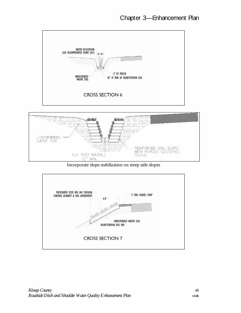
3.8 Conceptual Drawings 3.8.1 Enhanced Cross Sections The following drawings show the enhancement concepts for each cross section identified in Section 3.3. The ditch is typically limited in space and it may be difficult to provide the optimal components for treatment. The designer should refer to the key components to enhance water quality in Chapter 2 and incorporate as much as possible into the designs. Generally, enhancements to the ditch section include: • Amended soils 8- to 18-inches deep. (Full width of the ditch where applicable) • Plantings (See Section 3.7 Plantings) • Mulch layer (2” minimum depth) • Gravel (2” minimum depth)

Chapter 3—Enhancement Plan
Kitsap County 47 Roadside Ditch and Shoulder Water Quality Enhancement Plan otak
Chapter 3—Enhancement Plan
Kitsap County 48 Roadside Ditch and Shoulder Water Quality Enhancement Plan otak
Incorporate slope stabilization on steep side slopes

Chapter 3—Enhancement Plan
Kitsap County 49 Roadside Ditch and Shoulder Water Quality Enhancement Plan otak
3.8.2 Enhanced Cross Section 1-6 Enhancements for cross sections 1 through 6 include 8- to 18-inches of compost amended soils to ditch bottom. The limits of excavation for the amended soils will depend on the ditch bottom width and steepness of the sides lopes. Excavation should not undermine or destabilize the stability of the side slopes as seen in cross section 1 and 6. If the side slopes are approximately greater than 2:1 than excavation can, as a rule of thumb, extend to the height of the top of the fore slope (See cross sections 3 and 5). The 2” minimum depth gravel strip shall always be applied to cross sections 1, 3, and 5 and should be considered for cross sections 2, 4, and 6 if evidence of local erosion is present. Mulch is not required in ditches that convey a perennial stream or experiences standing water due to seasonal high ground water. Cross section 1 presents the special case of a steep and high back slope to the ditch. Enhancements should include stabilization of the steep side slope.

Chapter 3—Enhancement Plan
Kitsap County 50 Roadside Ditch and Shoulder Water Quality Enhancement Plan otak
3.8.3 Enhanced Embankment Fill Slope Dispersion of stormwater over a vegetated embankment can provide water quality enhancement. This enhancement is similar to a compost amended filter strip. Stormwater is routed over the embankment, the flows are spread out at the top of the embankment with a gravel flow spreader and treatment is provided through the vegetation and amended soils on the embankment. Construction of the compost amended embankment fill slope should be in accordance with BMP T9.4 of the Stormwater Management Manual for Western Washington (Figure 3.8.3a). See Cross Sections 7 and 8.
Figure 3.8.3a BMP T9.4 Compost Amended Filter Strip.

Chapter 3—Enhancement Plan
Kitsap County 51 Roadside Ditch and Shoulder Water Quality Enhancement Plan otak
3.9 Example Enhancement Project Roadside ditch and shoulder water quality enhancement projects can be developed by following the enhancement plan decision process. Figures 3.9a, 3.9b, 3.9c, and 3.9d show examples of how the components of the plan can be put together for a specific site. The examples show an enhancement projects for each of the enhancement types.

Chapter 3—Enhancement Plan
Kitsap County 52 Roadside Ditch and Shoulder Water Quality Enhancement Plan otak
This page intentionally left blank

!!!!!!!!!!!!!!!!!!
!!!!!!!!!!!!!!!!!!!!!!!!!!!!!!!!!!!!!!!!!!!!!!!!!!!!!!!!!!!!!!!!!!!!!!!!!!!!!!!!!!!!!!!!!!!!!!!!!!!!!!!!!!!!!!!!!!!!!!!!!!!!!!!!!!!!!!!!!!!!!!!!!!!!!!
! ! !! ! !
! ! !! ! !
! ! !! ! !
! ! !! ! !
! ! !! ! !
! ! !! ! !
! ! !! ! !
! ! !
Puget Sound
LEMOLO SHORE DR NE
Legend
éééé
éééééééé
éééé éé éé ééBIORETENTION AREA
SHORELINE
CULVERT! ! ! ! ! ! ! ! ! DITCH
PIPE
SWALE
TRENCH
A
A
PHOTOGRAPH OF EXISTING CONDITIONS NEAR A-A,
B
B
ROADSIDE DITCH CONDITIONS: -MODERATE TO FLAT SLOPE -MOSTLY WET IN THE WINTER, PONDING WATER -BACKSIDE OF DITCH EVEN WITH EDGE OF ROAD
ROADSIDE DITCH CONDITIONS: -STEEP SLOPE -MOSTLY DRY, SMALL RUNOFF DURING STORMS -BACKSIDE OF DITCH HIGHER THAN EDGE OF ROAD -CONSIDER USING SMALL CHECK DAMS
PHOTOGRAPH OF EXISTING CONDITIONS NEAR B-B, FACING EAST.FACING EAST.
DITCH TYPE: CULVERT CROSSING DITCH TYPE: WATER QUALITY DITCHSUBTYPE: STEEP SLOPE
CROSS SECTION A-A CROSS SECTION B-B
KITSAP COUNTY WATER QUALITYRETROFIT PROJECT
OTAK PROJECT #31820
Disclaimer: The information shown in this map is assembled GIS data created and acquired by Otak Inc., from Kitsap County GIS and from Bing Mapsonline. This data is not to survey accuracy and is meant for planningpurposes only.
KITSAP COUNTY WATER QUALITYRETROFIT PROJECT
OTAK PROJECT #31820
DATE: 5/04/2012
³ 0 10 20 30 405Feet
INSTALL STRUCTURE: -CATCH BASIN
CATCH BASIN


KITSAP COUNTY WATER QUALITYRETROFIT PROJECT
OTAK PROJECT #31820
Disclaimer: The information shown in this map is assembled GIS data created and acquired by Otak Inc., from Kitsap County GIS and from Bing Mapsonline. This data is not to survey accuracy and is meant for planningpurposes only.
KITSAP COUNTY WATER QUALITYRETROFIT PROJECT
OTAK PROJECT #31820
DATE: 5/04/2012
! ! !! ! !
! ! !! !
!!!!!!!!!!!!!!!!!!!!!!!!!!!!!!!!!!!!!!!!!!!!!!!!!!!!!!!!!!!!!!!!!!!!!!!!!!!!!!!!!!!!
!!!!!!!!!
!!!!!!!!!
!!!!!!
!!!!!!
!!!!!!
!!!!!!
!!!!!!
!!!!!!
!!!!!!
!!!!!!
!!!!!!
!!!!!!
! ! ! ! ! ! ! ! ! ! ! ! ! ! ! ! ! ! ! ! ! ! ! ! ! ! ! ! ! ! ! ! ! ! ! ! ! ! ! ! ! ! ! ! ! ! ! ! ! ! ! !
BEACH DR E
Legend
éééé
éééééééé
éééé éé éé ééBIORETENTION AREA
SHORELINE
CULVERT! ! ! ! ! ! ! ! ! DITCH
PIPE
SWALE
TRENCH
PHOTOGRAPH OF EXISTING CONDITIONS NEAR A-A, FACING WEST.
³ 0 10 20 30 405Feet
ROADSIDE DITCH CONDITIONS: -MODERATE TO FLAT SLOPE -WET IN THE WINTER, DRY DURING SUMMER MONTHS -BACKSIDE OF DITCH EVEN WITH EDGE OF ROAD
ROADSIDE DITCH CONDITIONS: -MODERATE TO FLAT SLOPE -WET IN THE WINTER, DRY DURING SUMMER MONTHS -BACKSIDE OF DITCH EVEN WITH EDGE OF ROAD
PHOTOGRAPH OF EXISTING CONDITIONS NEAR B-B, FACING WEST.
B
B
A
A
DITCH TYPE: SHORELINE CROSSING CULVERT
INSTALL STRUCTURE: -CATCH BASIN
CATCH BASIN DITCH TYPE: SHORELINE CROSSING CULVERT
CROSS SECTION A-A CROSS SECTION B-B


KITSAP COUNTY WATER QUALITYRETROFIT PROJECT
OTAK PROJECT #31820
Path
: K:\p
roje
ct\3
1800
\318
20\G
IS\m
xds\
Map
s by
Typ
e\ty
pe1
AND
TY
PE
6.m
xd
Disclaimer: The information shown in this map is assembled GIS data created and acquired by Otak Inc., from Kitsap County GIS and from Bing Mapsonline. This data is not to survey accuracy and is meant for planningpurposes only.
KITSAP COUNTY WATER QUALITYRETROFIT PROJECT
OTAK PROJECT #31820
DATE: 5/04/2012
!!!!!!
!!!!!!
!!!!!!
!!!!!!
!!!!!!
!!!!!!
!!!!!!
!!!!!!
!!!!!!
!!!!!!
!!!!!!
!!!!!!
!!!!!!
!!!!!!
!!!!!!
!!!!!!
!!!!!!
!!!!!!
!!!!!!
!!!!!!
!!!!!!
!!!!!!
!!!!!!
!!!!!!
!!!!!!
!!!!!!
!!!!!!
!!!!!!
!!!!!!
!!!!!!
!!!!!!
!!!!!!
!!!!!!
!!!!!!
!!!!!!
!!!!!!
!!!!!!
!!!!!!
!!!!!!!!!!!!!!!!!!!!!!!!!!!!!!!!!!!!!!!
!!!
!!!
!!!
!!!
!!!
!
! ! ! ! ! ! ! ! ! ! ! ! ! ! ! ! ! ! ! ! ! ! ! ! ! ! ! ! ! ! ! ! ! ! ! ! ! ! ! ! ! ! ! ! ! ! ! ! ! ! ! ! ! ! ! ! ! ! ! ! ! ! ! ! ! !
!!!!!!
!!!!!!
!!!!!!
!!!!!!
!!!!!!
!!!!!!
!!!!!!
!!!
!!!
!!!
!!!
!!!
!!!
!!!
!!!
!!!
!!!
!!!
!!!
!!!
!!!
!!!
!!!
!!!
!!!
!!!
!!!
!!!
! ! !! ! !
! ! !! ! !
! ! !! ! !
! ! !! ! !
! ! !! ! !
! ! !! ! !
! ! !! ! ! ! ! ! ! ! ! ! ! ! ! ! ! ! ! ! ! ! ! ! ! ! ! ! ! ! ! ! ! ! ! ! ! ! ! ! ! ! ! ! ! ! ! ! ! ! ! ! ! ! ! ! ! ! ! ! ! ! ! ! ! ! ! ! ! ! ! ! ! !
!!
!
!!!
!!
!
!!
!
!!
!
!!
!
!!
!
!!
!
Legend
éééé
éé éé éé éé
éé
éééééééé BIORETENTION AREA
SHORELINE
CULVERT! ! ! ! ! ! ! ! ! DITCH
PIPE
SWALE
TRENCH
A
A
PHOTOGRAPH OF EXISTING CONDITIONS NEAR A-A, FACING NORTH.
³
0 10 20 30 405Feet
B
B
ROADSIDE DITCH CONDITIONS: -MODERATE TO FLAT SLOPE -MOSTLY WET IN THE WINTER, PONDING WATER -BACKSIDE OF DITCH EVEN WITH EDGE OF ROAD -STEEP SIDESLOPES
ROADSIDE DITCH CONDITIONS: -STEEP FORESLOPE -DRY, SMALL RUNOFF DURING STORMS -NO DEFINED DITCH CHANNEL
PHOTOGRAPH OF EXISTING CONDITIONS NEAR B-B, FACING SOUTH.
DITCH TYPE: RURAL WATER QUALITY DITCH TYPE: BRIDGE OR CULVERT STREAM CROSSING
CROSS SECTION A-A CROSS SECTION B-B


KITSAP COUNTY WATER QUALITYRETROFIT PROJECT
OTAK PROJECT #31820
Path
: K:\p
roje
ct\3
1800
\318
20\G
IS\m
xds\
Map
s by
Typ
e\U
rban
Roa
dway
WQ
Trea
tmen
t.mxd
Disclaimer: The information shown in this map is assembled GIS data created and acquired by Otak Inc., from Kitsap County GIS and from Bing Mapsonline. This data is not to survey accuracy and is meant for planningpurposes only.
KITSAP COUNTY WATER QUALITYRETROFIT PROJECT
OTAK PROJECT #31820
DATE: 5/04/2012
!!
!!
!!
!!
!!
!!
!!
!!
!!
!!
!
!!
!!
!!
!!
!!
!!
!!
!!
!!
!!
!!
!!
!!
!!
!!
!!
!
!!
!
!!
!
!!
!
!!!
!!
!
!!
!
!!
!!
!!
!!
!!
!!
!!
!!
!!
!!
!!
!!
!!
!!
!!
!!
!
!!
!
!!
!!
!!
!!
!!
!!
!!
!!
Legend
éééé
éé éé éé éé
éé
éééééééé BIORETENTION AREA
SHORELINE
CULVERT! ! ! ! ! ! ! ! ! DITCH
PIPE
SWALE
TRENCH
³0 20 4010
Feet
ROADSIDE DITCH CONDITIONS: -MODERATE TO STEEP SLOPE -DRY, SMALL RUNOFF DURING STORMS -BACKSIDE OF DITCH LOWER THAN EDGE OF ROAD
PHOTOGRAPH OF EXISTING CONDITIONS NEAR A-A, FACING SOUTH.
DITCH TYPE: URBAN ROADWAY
CROSS SECTION A-A CROSS SECTION B-B
ROADSIDE DITCH CONDITIONS: -MODERATE TO STEEP SLOPE -CONCRETE BURIED FLUSH TO EXISTING GROUND PLANTER BOX
A
A
B
BSTORMDRAIN SYSTEM


Chapter 4—Construction Considerations
Kitsap County 61 Roadside Ditch and Shoulder Water Quality Enhancement Plan otak
This Chapter is dedicated to construction consideration for the various enhancement types outlined in Chapter 3. The retrofit options proposed in this Plan are cost-effective, reliable and relatively easy to maintain as they require known and often used construction methods. The following construction considerations include: • Construction timing • Preparation of ditch • Sediment and erosion control • Plant installation timing • Irrigation • Construction methods
4.1 Construction Timing In general, roadside ditch and embankment clearing and excavation, catch basin installation, and check dam construction should occur during the dry summer months from May 1 to September 30. Permanent landscaping and/or temporary erosion control measures must be in place no later than the first week of October to protect exposed soils from winter rains. 4.2 Preparation of Ditch 4.2.1 Soil Excavation Excavation should be performed to the extents shown on the cross section or to the maximum extent possible within right-of-way constraints. Machinery should be operated adjacent to the ditch and no heavy equipment should be allowed in the bottom of the ditch to minimize disturbance and compaction of the undisturbed soil in the bottom of the ditch. Excavation depth should be limited to the extents shown on the typical section, or to the maximum extent possible within the right-of-way. If construction activities have caused accumulation of fine materials, this material should be removed with light equipment and the underlying soil scarified. If there is a steep slope adjacent to the ditch, soil within the toe of the slope should not be removed. Areas of dense native vegetation with intact soil that appear to be a highly functioning water quality ditch should not be removed. 4.2.2 Bioretention Soil The bioretention soil should replace the excavated ditch soil. Use a bioretention amended soil specification consistent with the guidelines in the Kitsap County LID Guidance Manual.
Construction of enhanced ditch. (Source: Seattle Public Utilities)

Chapter 4—Construction Considerations
Kitsap County 62 Roadside Ditch and Shoulder Water Quality Enhancement Plan otak
The bioretention soil mixture should be placed and graded by excavators or heavy equipment. Onsite soil mixing of native material and compost should be avoided when native material is saturated or contains invasive and/or noxious weeds. Any accumulation of debris or sediment that takes place should be removed prior to installation. The bioretention soil should be installed at 12-inch maximum lifts and not compacted.
4.3 Sediment/Erosion Control 4.3.1 During Construction Soil stabilization and erosion control measures should be appropriate for the time of year, site conditions, estimated duration of use, and potential water quality impacts that stabilization agents may have on downstream waters. The following general considerations should be applied to the roadside water quality enhancement construction: • Prevent pollutant release. Select source control BMPs as a first line of defense. Prevent
erosion rather than treat turbid runoff. • Select sediment and erosion control techniques depending on site characteristics
(topography, drainage, soil type, ground cover, and critical areas) and the construction plan.
• Divert runoff away from exposed areas wherever possible. Keep clean water clean. • Limit the extent of clearing operations. • Before reseeding a disturbed soil area, amend all soils with compost wherever topsoil has
been removed. • Reduce runoff velocities to prevent channel erosion with check dams. • Prevent the tracking of sediment off-site. • Soils should be stabilized at the end of work day, weekend or holiday if needed based on
weather conditions. • Sediment deposited during construction activities should be removed and surface
scarified. 4.3.2 Suggested Erosion Control BMPs Best Management Practices (BMPs) are defined as schedules of activities, prohibitions of practices, maintenance procedures, and structural and/or managerial practices, that when used singly or in combination, prevent or reduce the release of pollutants to waters of Washington State. The following BMPs (Table 4.3.2.a) are suggested based in part on BMPs defined in Volume II- Construction Stormwater Pollution Prevention of the Stormwater Management Manual for Western Washington (SMMWW) by Washington State Department of Ecology (Ecology) and Washington State Department of Transportation (WSDOT) Highway Runoff Manual (HRM).

Chapter 4—Construction Considerations
Kitsap County 63 Roadside Ditch and Shoulder Water Quality Enhancement Plan otak
Table 4.3.2.a Erosion Control BMPs
BMP Reference Source Purpose Installation Specification
Mulching C121—Ecology 6A-2.2 – WSDOT
To provide immediate temporary protection from erosion. Mulch also enhances plant establishment by conserving moisture, holding fertilizer, seed, and topsoil in place, and moderating soil temperatures.
Mulch used within the ordinary high-water mark of surface waters should be selected to minimize potential flotation of organic matter. Composted organic materials have higher specific gravities (densities) than straw, wood, or chipped material.
Blankets C122 – Ecology 6A-2.3 – WSDOT
Erosion control nets and blankets are intended to prevent erosion and hold seed and mulch in place on steep slopes and in channels so that vegetation can become well established. In addition, some nets and blankets can be used to permanently reinforce turf to protect drainage ways during high flows.
Installation is critical to the effectiveness of these products, see figures provided in the Vol. II of the SMMWW and HRM.
Compost Filter Berm
C232 – Ecology 6A-2.29 – WSDOT
Filter berms have two main functions: to prevent concentrated flows from damaging exposed cut/fill slopes and to provide perimeter containment of sediment at the toe of a slope.
Spacing of berms:• Every 300 feet on slopes less than 5 percent • Every 200 feet on slopes between 5 percent and 10 percent • Every 100 feet on slopes greater than 10 percent

Chapter 4—Construction Considerations
Kitsap County 64 Roadside Ditch and Shoulder Water Quality Enhancement Plan otak
Table 4.3.2.a Erosion Control BMPs
BMP Reference Source Purpose Installation Specification
Compost Sock 6A-2.26 – WSDOT A perimeter control device to trap sediment and slow down runoff. Compost socks can be used in place of silt fence in some areas where low stormwater flows are expected. They are especially useful near sensitive areas where soil disturbance should be kept to a minimum.
WSDOT Standard Plan: I-30.40-00 – Compost Sock
Temporary and Permanent Seeding
C120 – Ecology 6A-2.1 – WSDOT
By protecting bare soil from raindrop impact and binding the soil with its roots, a well-established vegetative cover is one of the most effective methods of reducing erosion.
The application of agricultural chemicals to promote grass establishment must be conducted in a manner and at application rates that will not result in loss of chemicals to stormwater runoff. Manufacturers’ recommendations for application rates and procedures must be followed

Chapter 4—Construction Considerations
Kitsap County 65 Roadside Ditch and Shoulder Water Quality Enhancement Plan otak
Table 4.3.2.a Erosion Control BMPs
BMP Reference Source Purpose Installation Specification
Interceptor Dike and Swale
C200 – Ecology 6A-2.19 – WSDOT
Provide a ridge of compacted soil, or a ridge with an upslope swale, at the top or base of a disturbed slope or along the perimeter of a disturbed construction area to convey stormwater. Use the dike and/or swale to intercept the runoff from unprotected areas and direct it to areas where erosion can be controlled. This can prevent storm runoff from entering the work area or sediment-laden runoff from leaving the construction site.
• Use when a concentrated flow of water needs to be dispersed over a large area with existing stable vegetation.
• Use only where the slopes are gentle, the water volume is relatively low, and the soil will absorb most of the low-flow events.
• Use above areas that are stabilized by vegetation. • If the level spreader has any low points, flow will concentrate, creating channels
and possibly causing erosion. • Design the level spreader so that runoff does not reconcentrate after release unless
intercepted by another downstream measure. • Level spreaders consisting of gravel or organic material should have a minimal
amount of fine particles that could negatively influence turbidity. • The spreader should span the full width of the channel. Use multiple spreaders for
higher flows. • The depth of the spreader, as measured from the lip, should be uniform across the
entire width. • Level spreaders should be set back from the property line unless there is an
easement for flow.

Chapter 4—Construction Considerations
Kitsap County 66 Roadside Ditch and Shoulder Water Quality Enhancement Plan otak
Table 4.3.2.a Erosion Control BMPs
BMP Reference Source Purpose Installation Specification
Channel Lining
C202 – Ecology
To protect erodible channels by providing a channel liner using blankets.
• When a permanent ditch or pipe system is to be installed and a temporary measure is needed.
• In almost all cases, synthetic and organic coconut blankets are more effective than riprap for protecting channels from erosion. Blankets can be used with and without vegetation. Blanketed channels can be designed to handle any expected flow and longevity requirement. Some synthetic blankets have a predicted life span of 50 years or more, even in sunlight.
• Blankets usually only require laborers with hand tools, and sometimes a backhoe. • Rock is not easily obtainable or is very expensive to haul to a site. Rock requires
the use of dump trucks to haul and heavy equipment to place. • The Federal Highway Administration recommends not using flexible liners
whenever the slope exceeds 10 percent or the shear stress exceeds 8 lbs/ft2. Check Dams C207 – Ecology
6A-2.21 – WSDOT Construction of small dams across a swale or ditch reduces the velocity of concentrated flow and dissipates energy at the check dam.
WSDOT Standard Plan: I-50.20-00 – Check dams
Storm Drain Inlet protection
C232 – Ecology 6A-2.30 – WSDOT
To prevent sediment from entering an enclosed drainage system where the material can be readily washed downstream. Inlet protection is often the last opportunity to minimize sediment impact to a receiving water body.
WSDOT Standard Plan: I-40.20-00 – Storm Drain Inlet Protection
Straw Bale Barrier
C230 – Ecology 6A-2.28 – WSDOT
To intercept sheet flow and detain small amounts of sediment from disturbed areas.
WSDOT Standard Plan: I-30.50-00 – Straw Bale Barrier

Chapter 4—Construction Considerations
Kitsap County 67 Roadside Ditch and Shoulder Water Quality Enhancement Plan otak
Table 4.3.2.a Erosion Control BMPs
BMP Reference Source Purpose Installation Specification
Silt fence C233 – Ecology 6A-2.27 – WSDOT
Use of a silt fence reduces the transport of coarse sediment from a construction site by providing a temporary physical barrier to sediment and reducing the runoff velocities of overland flow.
WSDOT Standard Plan: I-30.10-00 – Silt Fence
Straw wattles C232 – Ecology 6A-2.25 – WSDOT
The two main purposes of wattles are to reduce slope length and to trap sediment. Cutting a slope length in half reduces erosion potential by a factor of four. Wattles also trap sediment, whether used on a slope or as a perimeter control device.
• It is critical that wattles are installed perpendicular to the flow direction and parallel to the slope contour.
• Narrow trenches should be dug across the slope on contour to a depth of 3 to 5 inches on clay soils and soils with gradual slopes. On loose soils, steep slopes, and areas with high rainfall, the trenches should be dug to a depth of 5 to 7 inches, or 1/2 to 2/3 of the thickness of the wattle.
• Start building trenches and installing wattles from the base of the slope and work up. Excavated material should be spread evenly along the uphill slope and compacted using hand tamping or other methods.
• Construct trenches at contour intervals of 3 to 30 feet apart depending on the steepness of the slope, soil type, and rainfall. The steeper the slope the closer together the trenches.
• Install the wattles snugly into the trenches and abut tightly end to end. Do not overlap the ends.
• Install stakes at each end of the wattle, and at 4-foot centers along entire length of wattle.
• If required, install pilot holes for the stakes using a straight bar to drive holes through the wattle and into the soil.
• At a minimum, wooden stakes should be approximately 3/4 x 3/4 x 24 inches. Willow cuttings or 3/8-inch rebar can also be used for stakes.

Chapter 4—Construction Considerations
Kitsap County 68 Roadside Ditch and Shoulder Water Quality Enhancement Plan otak
Table 4.3.2.a Erosion Control BMPs
BMP Reference Source Purpose Installation Specification
Sediment trap C240 – Ecology 6A-2.31 – WSDOT
A sediment trap is a small temporary ponding area with a gravel outlet used to collect and store sediment from sites cleared and/or graded during construction. Sediment traps, along with other perimeter controls, shall be installed before any land disturbance takes place in the drainage area.
WSDOT Standard Plan: I-30.10-00 – Miscellaneous Erosion Control Details. Sizing of a sediment trap is very specific. See referenced BMP section in the SMMWW and HDR for guidance.

Chapter 4—Construction Considerations
Kitsap County 69 Roadside Ditch and Shoulder Water Quality Enhancement Plan otak
4.3.3 Post Construction Soils at and adjacent to the roadside enhancement should remain stable and all temporary and permanent sediment and erosion control measures selected should be monitored, maintained and functional after construction activities are complete. Repairs should be conducted promptly as needed to assure continued performance of their intended function. See Chapter 5—Maintenance Considerations.
4.4 Planting 4.4.1 Installation Timing While many ditch restoration projects occur between April and October due to the dry season, plant installation should ideally be done during the wet season. It is recommended that the ditch restoration be completed during the dry season and the installation of plants reserved until the wet season begins. Use a broad spectrum aquatic herbicide like Rodeo or Aquamaster to kill weeds that establish themselves in the newly restored ditch prior to plant installation. The manufacturer’s time period between herbicide application and plant installation should be carefully followed. In order to maximize the plants survival, seed should be installed between March 1 and May 15 or September 1 and October 1 and plants should be installed between October and April (wet season). Installing plants in this timeframe will minimize the need for irrigation during the height of summer (July through September). Irrigation may be necessary during lengthy droughts or extended periods of unusually high temperatures, depending on the establishment of the plantings. Plantings installed in April in full sun and exposed to wind are more likely to require irrigation during the dry and/or heat of July, August and early September than an installation in similar characteristics completed two years prior. Although even some established plantings may die if the drought or period of high temperatures is extensive. 4.4.2 Mulch Mulch selection for erosion protection, conserving moisture and moderating soil temperatures should carefully consider its potential for washing away and the plant material it is accompanying. Coarse organic compost can be used as mulch. Arborist Wood Chip Mulch can also be considered for mulching around woody plants and a long-term hydraulically applied mulch (per WSDOT standards) can be considered when applying seed mixtures. The arborist wood chip mulch is inexpensive, readily available from tree care operations and it’s irregular, interconnected structure retain soil moisture, moderate soil temperature, suppress weeds better than more expensive, uniform sized bark mulches.

Chapter 4—Construction Considerations
Kitsap County 70 Roadside Ditch and Shoulder Water Quality Enhancement Plan otak
4.5 Construction Methods 4.5.1 Bioretention Facilities Bioretention facilities require special construction materials including: • Bioretention (amended) soils • Specific planting plans (native or adapted plants) • Shredded Bark Mulch composition layer Minimize compaction of the base and sidewalls of the bioretention facilities. Excavation should not be allowed during wet or saturated conditions. Excavations should be performed by machinery operating adjacent to the bioretention facilities and no heavy equipment with narrow tracks, narrow tires, or large-lugged, high-pressure tires is allowed on the bottom of the bioretention facilities. Construction of a bioretention facility requires specific site conditions and techniques including: • Little to no soil compaction. Keep equipment off the bottom of the ditch. • Excavation should not occur when soil is wet or saturated. • Erosion and sediment control measures. Onsite soil mixing or placement should not be performed if the soil is saturated. The bioretention facilities soil mixture should be placed and graded by excavators and/or backhoes operating adjacent to the bioretention facilities. Areas of enhancement should be clearly marked before site work begins to avoid soil disturbance and compaction during construction. No vehicular traffic, except that specifically used to construct the facility, should be allowed within 10 feet of retrofitted ditch bottom areas. Access routes to the ditch for maintenance purposes must be shown on the plans. Public swales will need to provide a minimum 8-foot wide access route, not to exceed 10 percent in slope. Facilities should be designed to require mowing no more than once per year. Mulch layer should be a minimum of two inches and a maximum of three inches. The mulch layer should be shredded or chipped hardwood or softwood. The mulch should be free of weed seeds, soil, roots and other material that is not bole or branch material. Do not place grass clippings or pure bark as a mulch layer. 4.5.2 Embankment Fill Slope Dispersion of stormwater over a vegetated embankment can provide water quality enhancement. This enhancement is similar to a compost amended filter strip. Stormwater is routed over the embankment, the flows are spread out at the top of the embankment with a gravel flow spreader and treatment is provided through the vegetation and amended soils on the embankment. Construction of the compost amended embankment fill slope should be in

Chapter 4—Construction Considerations
Kitsap County 71 Roadside Ditch and Shoulder Water Quality Enhancement Plan otak
accordance with BMP T9.4 of the Stormwater Management Manual for Western Washington. During construction the following practices should be considered: • Consider underground utility crossings impacts. Allowable crossing through an
enhancement should be determined by the designer and approved by the County on a case-by-case basis.
• Avoid over-compaction during construction. • After construction keep all erosion and sediment controls under the enhancement. • Do not put the compost amended embankment fill slope into operation until areas of
exposed soil in the contributing drainage catchments have been sufficiently stabilized with vegetated filter strips

Chapter 4—Construction Considerations
Kitsap County 72 Roadside Ditch and Shoulder Water Quality Enhancement Plan otak
This page intentionally left blank

Chapter 5—Maintenance Considerations
Kitsap County 73 Roadside Ditch and Shoulder Water Quality Enhancement Plan otak
5.1 Introduction This Chapter discusses the maintenance consideration for the various enhancement types outlined in Chapter 3. The retrofit options proposed in this Plan are cost-effective, reliable and relatively easy to maintain. All of the retrofit options will require ongoing periodic maintenance to maintain high-quality, long-term performance of water quality treatment. The primary purpose of the stormwater collection system is to collect the runoff and convey it to the receiving water. Enhancements that will provide water quality benefits should not interfere with the conveyance and should not result in localized flooding or pose a safety risk. Proper plant selection and planting should not result in increased maintenance; however, special care in the areas of enhancements will be required. Treatment is provided by infiltration into the amended soils and filtration through the vegetation. Any maintenance measures should preserve and restore the soil and vegetation. The standard ditch cleaning methods may need to be changed to protect the plants. Whereas scraping the soil and vegetation to clean the ditch may not be appropriate, regular moving of the vegetation would not be required. Plant selection and establishment is critical to the long-term performance. Once the plants are established, periodic cleaning of trash and debris may be all that is required for maintenance. See Chapter 4 for considerations for plant establishment prior to construction. 5.2 Inspection Considerations Areas where water quality enhancements have been installed should be inspected annually to determine whether maintenance is necessary and the type of maintenance that is needed. Table 5.2.A provides a description for excellent to poor condition for vegetation, erosion, and sediment accumulation. The enhanced ditches and slopes should be maintained to provide sufficient conveyance, and prevent localized flooding. For optimal treatment capabilities, the enhanced section of the ditch should fall within the Good Condition range. If the inspection shows that the vegetation, erosion or sediment accumulation is within the Moderate to Poor Condition ranges, then maintenance may be needed. Maintenance should be performed to restore the enhancements to Good Condition.

Chapter 5—Maintenance Considerations
Kitsap County 74 Roadside Ditch and Shoulder Water Quality Enhancement Plan otak
Table 5.2.A Inspection Considerations
Excellent Condition Good Condition Moderate Condition
Poor Condition
Vegetation: Healthy vegetation covering at least 90% of the ditch bottom Erosion: No Erosion, channelization or scouring -No bare spots Sediment: No build up of sediment or debris -No non-designed obstructions to flow
Vegetation: Mostly healthy vegetation covering at least 75% of the ditch bottom Erosion: Some erosion, channelization or scouring -Minimal bare spots 10-20% Sediment: -Some build up of sediment or debris -Minimal non-designed obstructions to flow (over-grown vegetation, trash and rack blockages)
Vegetation: Some vegetation covering between 40 to 75% of the ditch bottom Erosion: Some Erosion, channelization or scouring -Many bare spots 20-40% Sediment: -Significant build up of sediment or debris Significant non-designed obstructions to flow (over-grown vegetation, trash rack blockage)
Vegetation: Poor or no vegetation covering less than 40% of the ditch bottom Erosion: Erosion, channelization or scouring -Many bare spots 40% or more Sediment: -Significant build up of sediment or debris -Significant non-designed obstructions to flow (over-grown vegetation, trash rack blockage)
5.3 Water Quality-Enhanced Ditch/Shoulder Maintenance Considerations Areas where water quality enhancements have been incorporated into the ditches / shoulders will require annual plant, soil, and mulch layer maintenance to ensure optimum infiltration, storage, and pollutant removal capabilities. First, identify where water quality enhancements are located; these areas will need special maintenance considerations as discussed in this chapter. In general, typical maintenance considerations for enhanced ditches and shoulders include routine maintenance considerations and repair considerations:

Chapter 5—Maintenance Considerations
Kitsap County 75 Roadside Ditch and Shoulder Water Quality Enhancement Plan otak
5.3.1 Routine Maintenance Considerations Mowing/Vegetation Removal • Select appropriate planting, so mowing is not required. • Whenever possible use mechanical methods of vegetation removal (i.e., weed whackers
to avoid compaction, remove dead plants) rather than applying herbicides. Sediment Removal • Remove sediment that has collected behind Check Dams as needed to prevent damage
to channel vegetation, allow the channel to drain through the stone check dam, and prevent large flows from carrying sediment over the dam.
• Removal of Mulch with Sediment Depositions. Erosion Control • Sediment shall be removed and tested for toxicants in compliance with current disposal
requirements if land uses in the drainage area include commercial or industrial zones, or if visual indications of pollution are noticed.
• Use mulch or other erosion control measures when soils are exposed. • Add rock or remove and replace rock to check dams as needed to maintain design
height, cross section and flow-through characteristics. Integrated Pest Management: Pesticides/Fertilizers • Implement Kitsap County’s IPM. • Use the IPM method instead of herbicides. If herbicides are necessary, select appropriate
less toxic types and apply directly to the problem areas (i.e. for noxious weed removal or invasive plant removal).
• Fertilizers will probably not be necessary. If necessary, apply a minimal amount of fertilizer and only during the dry season.
5.3.2 Repair Considerations Plant Material Care • Select appropriate vegetation based on the wet conditions of the ditch or slope • Schedule planting before October 1 if possible to provide an establishment period,
allowing maximum root development during cool, wet season. If necessary, planting can be pushed later in the fall, but exposed soil should be protected with mulch in October.
• Ditches should be planted with vegetation that can withstand relatively high velocity flows as well as wet and dry periods
• Use hand weeding where practical. • Avoid loosening the soil when conducting mechanical or manual weed control, as this
could lead to erosion.

Chapter 5—Maintenance Considerations
Kitsap County 76 Roadside Ditch and Shoulder Water Quality Enhancement Plan otak
Spills • Exercise spill prevention measures whenever handling or storing potential contaminants. • Clean up spills as soon as possible to prevent contamination of stormwater. Use
absorbent pads after each spill. • Inspect ditch to assess extent of spill. • Remove mulch layer and determine if containments have further infiltrated into the soils.
If necessary, remove and replace the amended soils layer and mulch layer. • Remove as much of the spill as possible from plants with oil absorbent pads. • If necessary, remove plants and replant. • Report spills to the Department of Ecology.

References
Kitsap County 77 Roadside Ditch and Shoulder Water Quality Enhancement Plan otak
References Elfering, J, and Biesboer, D.(2003). Improving the Design of Roadside Ditches to Decrease Transportation-Related Surface Water Pollution.


A p p e n d i x A — L i t e r a t u r e R e v i e w


K:\project\31800\31820\Reports\WQPlan\Draft final\Final\Appendix\A-Literature Review.doc
Appendix A – Literature Review Introduction Existing research and related information associated with the effectiveness of roadside ditches and shoulders for treatment of stormwater were reviewed and synthesized. This included research associated with ditch characteristics (geometry, vegetation, etc.) as well as innovative use of treatment within the ditch (i.e. filtration berms). This existing research and information will be the basis for roadside ditch and shoulder water quality enhancement recommendations. Summary of Findings The following characteristics contribute to effective pollutant removals and long-term sustainability of the ditch/shoulder enhancements to provide water quality treatment: • Ditch Configuration. Widen and flatten the ditch as much as possible and provide a
mechanism to spread out the flow. Better treatment is achieved when the water flowing through the vegetation is shallow. This may be difficult within a limited ROW.
• Length of Enhancement. Optimally, provide 130 feet of enhancement in the ditch prior to
discharge into the receiving waterbody. If this is not possible, provide as much length as possible.
• Soil Amendments. Optimally, provide 18 inches of soil amendment, however if this is not
possible, provide a depth as deep as possible. Existing soils in the ditch may need to be removed to provide for the amended soils. When removing soils from the ditch, do not cut into the toe of a steep adjacent slope.
• Check Dams. Check dams can be provided in ditches with steep slopes. In addition to slowing
the flow and spreading flows across the width of the ditch, the check dam will provide for an area for water to pool and promote infiltration.
• Plant Selection. Choose plants that are herbaceous and not woody. The dense herbaceous
leaves will slow the water movement, promote sedimentation, and help filter pollutants. • Flow Dispersion. Spread the flow as much as possible, within a ditch or over an embankment.
Channelized flow can cause erosion and gullies. Spreading the flow will put more of the water in contact with the vegetation and soil amendments and promote treatment.

K:\project\31800\31820\Reports\WQPlan\Draft final\Final\Appendix\A-Literature Review.doc
Literature Review King County, 2011. In-Line Ditch Stormwater Treatment BMP Program Final Report. Conducted Under the Stormwater Management Implementation Grant Program. Grant Number G0900039 This study explores the use of ditch BMPs to promote storage, treatment and infiltration of stormwater within the existing ditch network. The BMPs were designed to function within the constraints of road engineering and safety standards. Each BMP comprised a treatment cell encapsulated by a modified rock check dam placed in a roadside ditch. The treatment cell contained compost for water quality treatment. Together, the treatment cell and rock check dam were designed to decrease storm flow energy and volume via ponding and infiltration; and improve water quality via settling, adsorption and filtration. Water quality benefits were seen as modest decreases in pollutants including TSS, TKN, total metals (arsenic, chromium, copper, lead, nickel, zinc), dissolved metals (copper, lead and zinc), PAHs, and turbidity. Water quality benefits were achieved by detention, adsorption and filtering of stormwater through a filtration medium (coarse compost) placed directly into a treatment cell within the BMP. It is unclear how much of these benefits are due directly to filtering and/or adsorption and how much is due to the water quality benefits obtained through stormwater detention by the BMP structure itself. In general, the baseline concentrations measured for pollutants, especially metals and PAH were low in stormwater influent. Limitations in the effectiveness of water quality treatment include the amount, or cross-sectional area of compost that could be placed securely in the ditch relative to the volume of stormwater that the ditch carried. These BMP designs would be best utilized by placing them throughout an entire section of ditch, thereby minimizing the opportunity for pollutants and solids to accrue in the storm flow. Colwell, S, et. al. 2000. A Survey of Ditches Along County Roads for their Potential to Affect Storm Runoff Water Quality. Center for Urban Water Resources Management. A systematic survey of ditches was conducted to evaluate the water-quality performance of roadside ditches. Problems that are detrimental to water quality include: little to no vegetation, standing water, substantial siltation, yard waste, mowing near ditches land leaving grass clippings in the ditches, and steep side slopes with a maximum ratio of 2:1. The single most important factor in achieving runoff treatment and preventing ditches from becoming sediment sources is through uniform cover by fine, dense vegetation. Deposits of sediments, cut vegetation, litter, or a combination to these were the leading causes of reduced health on the ditch beds, with drought next. In persistently wet areas, planting wetland herbaceous species is the most cost-effective strategy. Continue to use U-shaped ditch profiles. Be aware of erosive velocities that will develop if ditches are placed on slopes steeper than four percent. Erosion at a steeply sloping point inlet can be avoided with an energy dissipater. Make slopes no steeper than 3:1. Attempt to avoid standing water by careful grading to avoid

K:\project\31800\31820\Reports\WQPlan\Draft final\Final\Appendix\A-Literature Review.doc
depressions in ditch beds and compaction of the soil. In ditches having a surface or subsurface base flow source, determine if conditions will support wetland herbaceous plants.
Minnesota Board of Water and Soil Resources. 2006. Public Drainage Ditch Buffer Study A fundamental purpose of this study was to assess the implementation of required grass buffer strips along public drainage ditches. Grassed channels and buffers along drainage ditches provide benefits in four primary categories: sediment and erosion control, water quality control, ecological and habitat benefits, and economic benefits. This study conducted a literature review of the benefits of grass buffers along watercourses and inferred the benefits of narrow buffers along drainage ditches.
Sediment and Erosion Control Grassed channels and buffers can reduce erosion and control sediment through four mechanisms:
• By trapping sediment through the use of dense grass stems. • By reducing the velocity of surface flow. This allows sediments to settle out of water and be
deposited before they reach the channels. • By stabilizing ditch banks, preventing soil detachment. • By moderating water flow in the ditch during storms, effectively reducing bed and bank
scour. Water Quality Grass buffers contribute significantly to water quality control by reducing the concentration of contaminants and pollutants in several ways, including:
• filtering out sediment and other particulate-bound pollutants/contaminants and decreasing the concentration of pollution in surface flow before it reaches a water course;
• increasing the infiltration rate within the buffer zone and consequently reducing surface runoff; and
• providing suitable areas for allowing biodegradation or biochemical circulation to occur. Benefits of Narrow Grass Buffers Along Drainage Ditches The benefits from narrow grass buffers along drainage ditches were inferred to include:
• stabilize ditch banks; • trapping of water-borne sediment and trapping of wind-born sediment; and • improving water quality through trapping of sediment and microbes and recycling of
nutrients.
Narrow grass buffer provide ecological and habitat benefits. The potential economic benefits of grass buffers are due to decreased ditch maintenance and cleaning costs. Elfering, J, and Biesboer, D. 2003. Improving the Design of Roadside Ditches to Decrease Transportation-Related Surface Water Pollution. The results suggest that properly designed, short (130-foot) vegetative strips and swales, which include peat and rock check dams can substantially reduce pollutant levels from the stormwater roadways. The objectives of this research project were to perform field tests on typical Minnesota

K:\project\31800\31820\Reports\WQPlan\Draft final\Final\Appendix\A-Literature Review.doc
vegetative swale and determine the pollutant removal efficiency under different storm conditions and to modify the swale with a simple rock and soil media system to limit non-point source pollution in stormwater. In analyzing the storms, it was evident that a 130-foot vegetative swale was effective at reducing total suspended solids and total phosphorus given an adequate vegetative cover. In conclusion the model vegetated ditch and check dam was found to reduce pollution in the swale by as much as 54 percent. The check dam was able to compensate for the lack of vegetation during these seasonal changes. The average removal efficiency of total phosphorus was 54 percent and ortho-phosphorus was 47 percent. Results show that filter used by MnDOT and stormwater managers will be more effective at mediating stormwater runoff only if they avoid laminar flow. Laminar flow can occur when you have large pore sizes. Smaller pore soils, such as peat soils, were able to retain the anion tracer throughout the 30 minute sampling period and indicate the ability of the peat to retain potassium bromide. Reiser, M. and Younge, D. 2005. Application of a Simplified Analysis Method for Natural Dispersion of Highway Stormwater Runoff Natural dispersion runoff infiltration performance was evaluated by utilizing simulated rainfall/runoff data collected using a field-scale rainfall simulator coupled with a numerical model to study the effects of slope length, angle, and impervious contributory area on natural dispersion applications. The use of Low Impact Development (LID) BMP design in lieu of traditional stormwater treatment is beneficial because it is more aesthetically acceptable by the public and also because of its ability to reduce maintenance needs and increase groundwater recharge. Comparisons between LID area slope and runoff are not conclusive and vegetative cover effect is the only considerable variation. The LID areas on the 3:1 and 4:1 slopes outperformed the 6:1 slope. This can be attributed to the relatively high micro topographic and micro porous characteristics. A summary of recommended changes to existing natural dispersion evaluation guidance is as follows:
1. Revise LID slope requirements to include up to 3:1 slopes. 2. Develop an LID Design Equation to determine LID length based on: Contributory roadway
width (ACP), Measured saturated conductivity (Ks), and design rainfall intensities.
Schneider, R. 2007. Roadside Ditch Management to Reduce Stormwater Runoff, and Mitigate Floods and Droughts, presented to Delaware River Basin Commission. Four recommendations for improving the rainwater runoff flow path.
1. Where possible, replace impervious surfaces with permeable surfaces. For croplands, improve soil infiltration using mulches and cover crops.
2. Disconnect house runoff from roadside ditches with the use of rain gardens, rain barrels, and low lying depressions to capture rain from rooftops.
3. Don’t scrape ditches and leave them exposed to erosion during storm events, instead use hydroseeding immediately after ditching early in the season to allow sufficient growing time.(If scraping is necessary, do it in patches with vegetated strips left downstream to capture sediments.
4. Disconnect ditches from streams and use infiltration ponds, infiltration basins or detention ponds that allows for groundwater recharge.

K:\project\31800\31820\Reports\WQPlan\Draft final\Final\Appendix\A-Literature Review.doc
Schneider, R. 2008. Win3! Basic Guidelines for Successful Roadside Ditch Management. Presented at Cornell Local Roads Conference. Guideline #1: Create and maintain a shallow, gently sloping ditch that will be easier to maintain by mowing. This will be safer for traffic and is less likely to erode. Don’t over ditch. 18-24 inches is plenty deep enough to carry away storm water. Avoid V-shaped ditch where the bottom is easily incised and starts the erosion process. Guideline #2: Plan ahead to prevent erosive water flows. Consider drainage areas upslope that may contribute to erosive flows. Use check dams to slow velocities. Guideline#3: Whenever possible, mow ditches regularly instead of scraping. Guideline #4: Minimize erosion of gravel and rocks that move as bed loads into streams. Guideline#5: Disconnect ditches from streams and use infiltration basins or detention ponds that allow for groundwater recharge. Guideline#6: Reduce transfer of runoff from land to ditches.
Schultz, D. Current Status of Vegetation Management in Roadside Ditches and Stormwater Management Facilities. Center for Urban Water Resources Management. This report compiled empirical evidence to evaluate the effects of different maintenance practices on the pollutant-removal capabilities of the facilities. The literature reviewed identified the following in relation to vegetation management and pollutant removal. Suitable filter grass species should (a) have a deep root system, (b) have a high stalk density, (c) be insensitive to submergence and droughts, and (d) be able to grow through sediment coverage (Van Dijk et al., (1995) refer to a 1967 paper by L.G. Wilson). In contrast, a study conducted in Florida in 1984 came to the conclusion that bare earthen (i.e., unvegetated) swales were more effective than grassed swales in the removal of heavy metals due to the higher surface area available for adsorption (Harper et al., 1985; Yousef et al., 1985). They suggested that the optimal strategy for increasing contact and residence times consisted of establishing a cover vegetation for erosion control, keeping the vegetation viable through removal of clippings, and planting a slow-growing species with low maintenance needs if possible. A biofiltration swale study (King County, 1992), conducted by King County and the cities of Seattle and Mountlake Terrace, recognized the likely importance of maintenance in facility performance. The study offered several judgments about the optimal characteristics and maintenance needs for vegetation in bioswales, based on general observation. It suggested that regular mowing is important for several reasons:
• It encourages higher density grass. • It keeps the grass from getting too long where it can become too heavy and lay over, which
tends to channelize flow and in turn reduces residence time and adsorption capability. • It maintains the grass at the height for which the swale was designed. • It provides for removal of vegetative litter (such as leaves) that can hinder grass vitality. • It prevents clogging of outflow structures through litter and clipping removal. • It can prevent the return of the nutrients to the receiving water system that have been taken
up by the plants if the clippings are removed.

K:\project\31800\31820\Reports\WQPlan\Draft final\Final\Appendix\A-Literature Review.doc
Removal of clippings is believed to be important as a primary mechanism to remove pollutants from the system. However, this is a very costly (and almost universally ignored) requirement.

A p p e n d i x B — K I T S A P S S W M S T A N D A R D
B I O R E T E N T I O N A N D G R E E N S T R E E T S P L A N T L I S T


KITSAP SSWM STANDARD BIORETENTION AND GREEN STREETS PLANT LIST SUBJECT TO SITE SPECIFIC APPROVAL IF USED IN R.O.W. Draft list: JULY 2012 Latin Name Common Name Zone/Moisture
Conditions Sun/Shade Preferences Mature Size Evergreen/
Deciduous Native: Yes/No
EMERGENT/ WETLAND PLANTS
Acorus gramineus ‘Ogon’ Golden Japanese Sweet Flag Zone 1 and 2 Sun to part
shade 10” tall by 18” wide Evergreen No
Acorus gramineus ‘Variegatus’
Variegated Japanese Sweet Flag Zone 1 and 2 Sun to part
shade 10” tall by 18” wide Evergreen No
Carex obnupta Slough Sedge Zone 1 Sun to part shade 1’-5’ tall Semi-
evergreen Yes
Carex stipata Sawbeak Sedge Zone 1 Sun to part shade 2’-3’ tall Deciduous Yes
Deschampsia cespitosa Tufted Hairgrass Zone 1 and 2 Sun to part shade 3’ tall Deciduous Yes
Juncus acuminatus Taper-tipped Rush Zone 1 Sun to part shade 1’-2’ tall Semi-
evergreen Yes
Juncus effusus Common Rush Zone 1 Sun to part shade 3’ tall Semi-
evergreen Yes
Juncus ensifolus Dagger-leaf Rush Zone 1 Sun to part shade 2’ tall Semi-
evergreen Yes
Juncus patens ‘Elk’s Blue’ Elk’s Blue Rush Zone 1 Sun to part shade 1’-2’ tall Evergreen No
Juncus tenuis Slender Rush Zone 1 Sun 2’ tall Semi-evergreen Yes
Scirpus microcarpos Small fruited bulrush Zone 1 Sun 2’-4’ tall Deciduous Yes
PERENNIALS/ GRASSES/ FERNS/ GROUNDCOVERS/ BULBS
Achillea millefolium Yarrow Zone 2 and 3 Sun to part sun 6”-2’ tall Deciduous Yes
Aquilegia formosa Western Columbine Zone 2 and 3 Part sun to shade 1’-3’ tall Deciduous Yes
Asarum caudatum Wild Ginger Zone 2 Part sun to shade < 6” tall Evergreen Yes
Aster subspicatus Douglas Aster Zone 2 and 3 Sun to part shade 2’ tall Deciduous Yes
Blechnum spicant Deer Fern Zone 2 Part to full shade 2’ tall by 2’ wide Evergreen Yes
Camassia quamash Camas (bulb) Zone 2 Sun to part sun 1’-2’ tall Deciduous Yes
Carex testacea New Zealand Orange Sedge Zone 2 and 3 Sun to part
shade 2’ tall Evergreen No
Echinacea purpurea Purple Coneflower Zone 2 and 3 Sun to part shade 2’-4’ tall Deciduous No
Elymus magellanicus* Blue Magellan Grass Zone 2 and 3 Sun to part shade 2’-4’ tall Deciduous No
Fragaria chiloensis Coastal Strawberry Zone 2 and 3 Sun to part shade Low growing Semi-
evergreen Yes
Fragaria chiloensis ‘Pink Panda’ or ‘Lil Diamond’
Pink flowering Coastal Strawberry Zone 2 and 3 Sun to part
shade Low growing Semi-evergreen No
Geranium macrorrhizum Hardy Geranium Zone 2 and 3 Sun to part shade 8”-12” tall Evergreen No
Geranium x cantabrigiense ‘Biokovo’ Biokovo Geranium Zone 2 and 3 Sun to part
shade 1’ tall by 1’ wide Evergreen No
Helictotrichon sempervirens Blue Oat Grass Zone 2 and 3 Sun 2’-3’ tall Evergreen No
Hemerocallis varieties Daylily Zone 2 and 3 Sun to part shade Varies Deciduous No
Heuchera varieties Coral Bells Zone 2 and 3 Sun to part shade 1’-2’ tall Evergreen No
Iris douglasiana Douglas Iris Zone 1 and 2 Sun to part shade 2’ to 3’ tall Evergreen Yes
Iris setosa* Wild Alaska Iris Zone 1 and 2 Sun to part shade 1’-2’ tall Deciduous No
Mimulus guttatus Yellow Monkey Flower Zone 1 and 2 Sun to part shade 2’ Deciduous Yes
Polystichum munitum Sword Fern Zone 2 and 3 Part sun to shade 3’-5’ tall Evergreen Yes
Rudbeckia Black eyed Susan Zone 2 and 3 Sun 2’-4’ tall Deciduous No
Sisyrinchium idahoensis Blue-eyed Grass Zone 1 and 2 Sun to part shade 2’ tall Deciduous Yes

KITSAP SSWM STANDARD BIORETENTION AND GREEN STREETS PLANT LIST SUBJECT TO SITE SPECIFIC APPROVAL IF USED IN R.O.W. Draft list: JULY 2012 Latin Name Common Name Zone/Moisture
Conditions Sun/Shade Preferences Mature Size Evergreen/
Deciduous Native: Yes/No
SHRUBS Cornus sericea ‘Kelseyi’**
Dwarf Red Twig Dogwood Zone 1 and 2 Sun to part
shade 2’-4’ tall by 3’-4’ wide Deciduous No
Cornus sericea ‘Flaviramea’ Yellow Twig Dogwood Zone 1 and 2 Sun to part
shade 6’-8’ tall by 7’-9’ wide Deciduous No
Lonicera involucrata Twinberry Zone 1 and 2 Part shade to shade 5’-8’ tall Deciduous Yes
Lonicera pileata Privet Honeyscukle Zone 2 and 3 Shade, part shade, full sun
2’-4’ tall by 5’-8’ wide Evergreen No
Mahonia aquifolium Tall Oregon Grape Zone 2 and 3 Sun to part shade 6’- 10’ tall Evergreen Yes
Mahonia aquifolium ‘Compacta’ Compact Oregon Grape Zone 2 and 3 Sun to part
shade 2’-3’ tall Evergreen No
Mahonia nervosa Cascade/Dull Oregon Grape Zone 2 and 3 Part shade to
shade 2’-3’ tall Evergreen Yes
Mahonia repens Creeping/Low Oregon Grape Zone 2 and 3 Sun to part
shade 2’ tall Evergreen Yes
Ribes sanguineum Red Flowering Currant Zone 3 and 3 Sun to part shade 3’-10’ tall Deciduous Yes
Rosa pisocarpa Swamp Rose Zone 1, 2 and 3 Sun 6’ to 8’ tall Deciduous Yes
Rosa nutkana Nootka Rose Zone 2 and 3 Sun 6’ to 8’ tall Deciduous Yes
Rubus parviflorus Thimbleberry Zone 2 Sun to part shade 4’ to 10’ tall Deciduous Yes
Salix purpurea ‘Nana’ Dwarf Arctic Willow Zone 1 and 2 Sun to part shade
4’-8’ tall by 4’-8’ wide Deciduous No
Spiraea X bumalda ‘Magic Carpet’ Magic Carpet Spiraea Zone 2 and 3 Sun to part
shade 2’-3’ tall Deciduous No
Spiraea japonica ‘Little Princess’ Little Princess Spiraea Zone 2 and 3 Sun to part
shade 2’-4’ tall by 2’-4’ wide Deciduous No
Symphoricarpos albus Snowberry Zone 2 and 3 Sun to part shade 6’ tall Deciduous Yes
LARGE SHRUBS/ SMALL TREES (use caution when placing large shrubs and trees)
Acer circinatum Vine Maple Zone 1, 2 and 3 Filtered sun to shade 13’-26’ tall Deciduous Yes
Betula nigra ‘Summer Cascade’
Summer Cascade River Birch Zone 2 and 3 Sun to part
shade 6’ to 8’ tall by 6’ to 8’ wide Deciduous No
Cornus sericea Red Twig Dogwood Zone 1, 2 and 3 Sun to part shade 15’ tall Deciduous Yes
Holodiscus discolor Oceanspray Zone 2 and 3 Sun to part shade 15’ tall Deciduous Yes
Myrica californica Pacific Wax Myrtle Zone 2 and 3 Sun 18’ tall Evergreen Yes
Physocarpus capitatus Pacific Ninebark Zone 1, 2 and 3 Sun to part shade 6’-13’ tall Deciduous Yes
TREES (is not intended to be a comprehensive list of potential street trees)
Amelanchier alnifolia Western Serviceberry Zone 2 Sun to part shade
20’ tall by 25’ wide Deciduous Yes
Betula albosinensis var. septentrionalis Chinese Red Birch Zone 2 and 3 Sun to part
shade 25’ tall by 15’ wide Deciduous No
Betula nigra River Birch Zone 2 and 3 Sun to part shade
20’ tall by 10’ wide Deciduous No
Betula utilis var. jacquemontii Himalayan White Birch Zone 2 and 3 Sun to part
shade 20’ tall by 10’ wide Deciduous No
Chamaecyparis nootkatensis ‘Pendula’
Weeping Alaska Yellow Cedar Zone 2 and 3 Sun to part
shade 30’ tall by 18’ wide Evergreen No
Rhamnus purshiana Cascara Zone 2 and 3 Sun to shade 30’ tall by 25’ wide Deciduous Yes
PLANT SELECTION CRITERIA: • Tolerate fluctuating soil moisture conditions, from ponding to dry • Require minimal maintenance and is drought tolerant once established • Contribute to ornamental and habitat value for both natural native areas and residential landscapes
ZONE DEFINITIONS adopted from the Low Impact Development Technical Guidance Manual for Puget Sound (January 2005): • Zone 1: Areas of periodic or frequent standing water • Zone 2: Periodically moist or saturated during larger storms • Zone 3: Dry soils infrequently subject to inundation or saturation
NOTES: • * Included on a trial basis • ** May be susceptible to fungal leaf spot