Fault Detection and Reconstruction for Discrete Nonlinear ...

HAL Id: hal-01710406https://hal.archives-ouvertes.fr/hal-01710406
Submitted on 15 Feb 2018
HAL is a multi-disciplinary open accessarchive for the deposit and dissemination of sci-entific research documents, whether they are pub-lished or not. The documents may come fromteaching and research institutions in France orabroad, or from public or private research centers.
L’archive ouverte pluridisciplinaire HAL, estdestinée au dépôt et à la diffusion de documentsscientifiques de niveau recherche, publiés ou non,émanant des établissements d’enseignement et derecherche français ou étrangers, des laboratoirespublics ou privés.
Road-line detection and 3D reconstruction using fisheyecameras
Rémi Boutteau, Xavier Savatier, Fabien Bonardi, Jean-Yves Ertaud
To cite this version:Rémi Boutteau, Xavier Savatier, Fabien Bonardi, Jean-Yves Ertaud. Road-line detection and 3Dreconstruction using fisheye cameras. 2013 16th International IEEE Conference on Intelligent Trans-portation Systems - (ITSC 2013), Oct 2013, The Hague, Netherlands. �10.1109/ITSC.2013.6728376�.�hal-01710406�

Road-line detection and 3D reconstruction using fisheye cameras
R. Boutteau, X. Savatier, F. Bonardi, J.Y. Ertaud
Institut de Recherche en Systemes Electroniques Embarques (IRSEEM)Technopole du Madrillet - Avenue Galilee76800 Saint Etienne du Rouvray - France
Abstract— In future Advanced Driver Assistance Systems(ADAS), smart monitoring of the vehicle environment is a keyissue. Fisheye cameras have become popular as they provide apanoramic view with a few low-cost sensors. However, currentADAS systems have limited use as most of the underlyingimage processing has been designed for perspective views only.In this article we illustrate how the theoretical work done inomnidirectional vision over the past ten years can help to tacklethis issue. To do so, we have evaluated a simple algorithmfor road line detection based on the unified sphere model inreal conditions. We firstly highlight the interest of using fisheyecameras in a vehicle, then we outline our method, we presentour experimental results on the detection of lines on a set of180 images, and finally, we show how the 3D position of thelines can be recovered by triangulation.
I. INTRODUCTION
In recent years, Advanced Driver Assistance Systems(ADAS), initially limited to luxury vehicles, have becomeavailable on high-volume models. Medium-sized cars arenow sold with ADAS features such as lane departure warn-ing, blind spot monitoring and road sign recognition. Asreported in [1] an impressive growth of the ADAS market isexpected, going from $10 billion in 2011 to $130 billionin 2016. This growth will be possible not only throughthe reduction of component costs but also with the inte-gration of new functions on the original architecture. Thisexplains why ADAS based on vision are one of the mostcommon schemes for driving assistance as cameras can beconsidered as versatile multifunction sensors. Recently, [25]has highlighted the performance potential of camera sensorcombined with increasingly competitive costs. In the future,as ADAS should offer more and more automated assistance,this will imply a robust and complete perception of thevehicle environment while maintaining affordable costs withsensor rationalization and fusion.
Monitoring the surrounding environment of a car canbe achieved using a very small number of cameras. Anomnidirectional observation of a scene is possible with asingle camera by combining it with a convex mirror. Such asystem, called a catadioptric sensor (association of a mirror(catoptric) and lenses (dioptric)), has been widely studiedin autonomous robotics [8][33][6]. Its use for automotiveapplications has also been explored [18][19][27]. However,this sensor is not optimal for the monitoring of the sur-rounding environment because objects close to the vehiclemay be occluded by the vehicle itself. Recently, the use
of multiple large field of view cameras has been proposed[10][21]. [29] has demonstrated the potential of such a sensorfor pedestrian detection in blind spot monitoring. Indeed,wide angle cameras such as fisheyes are particularly suitablefor lateral views as a single camera placed on the side canobserve all the surrounding objects from the rear to the frontof a car. Thus, only four wide angle cameras are needed toobtain a complete bird’s-eye view from above the vehicle asdemonstrated with the NISSAN Around viewTM monitor.
Theoretical works in omnidirectional vision have let to theformalization of a unified model which consists of a projec-tion onto a virtual unitary sphere. While initially restricted tocentral catadioptric sensors [14], this model has recently beenextended to fisheye cameras [7]. In past studies, we showedhow this framework can be helpful for 3D reconstruction [5]and how it can improve classical machine learning algorithmsfor image understanding [9]. In this paper, we want tohighlight the potential of such a model coupled with fisheyesensors for an ADAS application by applying it to road-marking detection. Road-marking detection is a basic step inmany ADAS functions such as lane-departure warning, lane-keeping and blind-spot control. In this paper, we present asimple and efficient algorithm for detecting lane markingusing lateral fisheye views. As a first step, the algorithm isrestricted to straight line detection and is evaluated in realconditions on a database of 180 images. Using our method,a 3D reconstruction of lines is possible, which facilitatesthe rejection of outliers and will be helpful in automatedguidance. In section II, we set out the state of the artwith regard to road-line detection algorithms in classicaland omnidirectional images. In section III, we present ournew algorithm for detecting straight lines in omnidirectionalimages. Section IV is dedicated to the experimental resultsobtained from this detection algorithm as well as to a straightline triangulation application. Lastly, in section V, we presenta conclusion and identify several directions for future work.
II. STATE OF THE ART IN METHODS FOR DETECTINGSTRAIGHT LINES IN OMNIDIRECTIONAL IMAGES
Road-marking detection for ADAS applications has beenwidely studied using monocular systems [22], stereovision[24] or more recently by fusion with navigation sensors[28] but most of the algorithms proposed are suitablefor perspective front views only. An interesting survey ofcommon algorithms can be found in [32]. Lane detection
obtained from lateral views is, however, particularly suitablein applications where lateral parts of the vehicle have to bemonitored. But in such a case, perspective cameras cannotbe used due to the fact that surrounding objects may be veryclose to the car. In [20], the authors demonstrated how thisissue can be tackled using fisheye cameras. They proposed amethod to detect road marking based on some assumptionsregarding the movement of cars. In [21] they also used theirline detection method for on-line fisheye calibration. Anotherinteresting use of fisheyes can be found in [16] where theauthors used this sensor for car recognition.
The detection of straight lines in omnidirectional images ismuch less easy than in perspective images as the projectionof lines onto an image plane no longer gives straight linesbut conic sections. The classical problem of detecting linesin perspective images therefore becomes a complex problemof detecting conics in omnidirectional images. There areseveral special cases which simplify the detection of linesin omnidirectional images. [34] and [8] were interestedin the detection of lines projected radially onto a conicalmirror. This configuration requires that the sensor be in avertical position and that there be sufficient vertical linesin the environment. [12] proposed a method for extractinghorizontal and vertical segments but not for every type ofstraight line. This limitation is due to the use of non-centralsensors which makes the detection of certain types of linesextremely complex. The same problem is covered in [26].For central sensors, the methods for estimating lines canbe classified into two main categories. The first categorytries to detect conic sections in the image and to estimatethe five parameters so that the conic section is adjusted tothe extracted data [36]. The computation time is generallylong and these algorithms are not efficient when only smallproportions of the conic sections are visible. Furthermore,these methods are often only applicable in the special case ofthe paracatadioptric sensor, a combination of a paraboloidalmirror and an orthographic camera, as the projections ofthe lines then become arcs of circles [2] [3] [30]. Thesecond category involves the detection of great circles on theequivalence sphere. It has been demonstrated in [15] that theprojection of a 3D line on the sphere is a great circle C asillustrated in Figure 1. These methods are only applicable tocalibrated sensors as it is necessary to be able to calculate theprojection of pixels on the equivalence sphere. [4] describessuch a method.
The main advantage of the detection of great circleson the equivalence sphere is that the algorithm can beused for all central sensors because it is a unified model.The detection of great circles is in general carried out bya Hough transformation [17], the difference between thevarious algorithms is the space in which the processing iscarried out. In [31], the great circles on the sphere are definedby their normal, characterized by the angles of elevationand azimuth. A Hough space based on these angles is thencreated and the detection of maxima in the Hough spaceenables the parameters for the lines to be obtained. Thereare other Hough spaces for characterizing the lines. It is for
Fig. 1. Projection of a line onto the equivalence sphere.
example possible to use either the normal directly [23] or itscubic coordinates [35]. However, the Hough transformationintroduces several problems such as the selection of the bestsampling step for the Hough space which should in additiontake account of the non-uniform resolution of the sensors. Inaddition, the detection of maxima in the Hough space is acomplicated step.
III. OUR METHOD
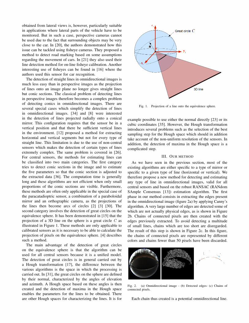
As we have seen in the previous section, most of theexisting algorithms are either specific to a type of mirror orspecific to a given type of line (horizontal or vertical). Wetherefore propose a new method for detecting and estimatingany type of line in omnidirectional images, valid for allcentral sensors and based on the robust RANSAC (RANdomSAmple Consensus [13]) estimation algorithm. The firstphase in our method consists in extracting the edges presentin the omnidirectional image (figure 2a) by applying Canny’salgorithm. A very large number of edges are detected some ofwhich are not actually physical edges, as is shown in Figure2b. Chains of connected pixels are then created with theedges previously extracted. To avoid detecting a multitudeof small lines, chains which are too short are disregarded.The result of this step is shown in Figure 2c. In this figure,the chains of connected pixels are represented by differentcolors and chains fewer than 50 pixels have been discarded.
Fig. 2. (a) Omnidirectional image - (b) Detected edges- (c) Chains ofconnected pixels.
Each chain thus created is a potential omnidirectional line.

It is therefore necessary to make a decision on whether itreally is a line and, if so, estimate its parameters. Omni-directional lines will be characterized by the normal to theplane which contains the line and which passes through thecenter of the equivalence sphere (see Figure 3).
Fig. 3. Characterisation of an omnidirectional line by a normal.
We propose to work directly on the unitary sphere S2 ∈R3. We characterize a line by the normal n ∈ S2
+ to theplane formed by the line and the center of projection. Allthe pixels in the chains are projected onto the equivalencesphere. This step, called lifting, requires knowledge of theintrinsic parameters of the sensor and therefore assumes thesensor to be calibrated. All the following calculations arecarried out using the points on the sphere. To estimate theparameters of the line which best correspond to the pointsin the chain, a robust estimation method called RANSACis used. Its pseudo-code is given in Algorithm 1. For eachchain, two points X1
S and X2S are taken randomly and the
normal to the plane passing through these two points and thecenter of the sphere is calculated:
n = λX1
S ×X2S
‖X1S ×X2
S‖, where λ ∈ {−1, 1} ensures that n ∈ S2
+
(1)The other points in the chain are then tested to decide
whether they belong to the great circle C given by:
C = {XS|nTXS = 0, ‖XS‖ = 1} (2)
In practice, because there are small errors due to noise, thediscretization of the image or calibration, an error thresholdis set to decide whether or not point XS belongs to thegreat circle C . All the points belonging to the great circle Cdefined by n are then stored in the memory. If the number ofpoints belonging to the circle C is greater than the minimumlength allowed for defining a line, then the pixel chain doesindeed relate to a line whose normal is re-estimated usingall the points belonging to the great circle. It is then possible
to define segments rather than lines by taking the first andlast pixel in the chain belonging to the great circle.
Algorithm 1 Pseudo-code for estimating omnidirectionallines using the RANSAC method.k ← 0while k < MAX ITERATIONS do
maybe inliers = 2 points selected randomlymaybe line = n estimated using these 2 pointsconsensus set = maybe inliersfor each point not in maybe inliers do
if the point complies with the model with an errorsmaller than MAX ERROR then
add the point to consensus setend if
end forend whileif the number of points in consensus set > THRESHOLDthen
This is definitely a line.Re-estimation of n with all the points in consensus set
end if
IV. EXPERIMENTAL RESULTS AND APPLICATION TO LINETRIANGULATION
A. Line detection
We applied this algorithm to the field of autonomouscomputer-aided driving, so we chose to place our camerasclose to the left and right rear-view mirrors of a car. Thecamera we used is a Prosilica GC1380C with a fisheye lens(Fujinon fisheye 1:1.4/1.8mm) reducing its region of interestto a resolution of 1024x1024 pixels so that the circular fieldof view is centered in the images. We pointed this sensortoward the road with an angle of about 45 ˚ in order to seeboth the immediate environment (road and blind spots of thecar) and the global environment (buildings for instance). Thesensor was calibrated using our omnidirectional calibrationtool1. During testing we drove both in urban zones and onhighways, with several quality levels of the road (texture,uniformity, etc) and its markings (good, damaged or miss-ing). We took 180 images, which were later processed withour algorithm. To evaluate the sensitivity of the processing,we calculated the True Positive Rate (TPR) according to thefollowing formula:
TPR =TP
TP + FN(3)
• True Positives (TP) are cases where there is a roadmarking or a border of the road in the image and thealgorithm detects it (see Figure 4a and 4b).
• False Negatives (FN) are cases where there is a line or aborder of the road in the image and the algorithm doesnot detect it (see Figure 4d).
1This software is available at http://omni3d.esigelec.fr/doku.php/omni/calib

• False Positives (FP) are cases where the algorithmdetects a line where there is none (see Figure 4c).
• During our tests, we did not encounter any True Nega-tives (TN), due to the fact that there was always a roadmarking or a border of the road in the field of view.
Fig. 4. Samples of line detection. (a) and (b) True Positives, (c) FalsePositive, (d) False Negative
The TP, FN and FP rates are given in Table I.As shown,we obtained a True Positive Rate of 86.9%.
TABLE IDETECTION RATES OBTAINED ON THE 180 IMAGES OF THE DATABASE
TP 81.11%FN 12.22%FP 6.67%
TPR 86.9%
B. 3D reconstruction
The detection of omnidirectional lines outlined aboveenables us to parameterize the line in the local referenceframe of the sensor, the line being represented by the normalto the plane containing the line and the center of the sensor.It is possible to triangulate the line, in order to obtain its3D position. This can be achieved if the pose (R, t) of thesensor relative to the road is known. In practice, we useda calibration pattern lying on the road to estimate the poseby solving an omnidirectional Perspective-N-Point problem[11].
Let (C1, x1, y1, z1) be the reference frame attached tothe vehicle (see Figure 5). The center C1 = [0 0 0]T islocated vertically below the omnidirectional sensor and onthe road level. n1 = [0 0 1]T is the normal of the road.
Let C2 = [c2x c2y c2z ]T be the center of the sensor, and
(C2, x2, y2, z2) the reference frame of this sensor. n2 =[n2x n2y n2z ]
T is the normal characterizing the line withinthe reference frame (C1, x1, y1, z1) . The objective is todetermine the parametric equation of the corresponding 3Dline L: L = A+ λu, where A is a point on the line and uits direction vector.
Fig. 5. Triangulation of an omnidirectional line.
The line verifies the equation of the two planes, therefore:
{z = 0
n2x .x + n2y .y + n2z .z − n2z .c2z = 0(4)
In z = 0 and x = 0, line L therefore passes through point
A with coordinates A =[0 n2z .c2z
n2y0]T
.The direction vector u of the line is obtained directly by
calculating the cross product of the normals of the two planesdefining this line:
u =n1 × n2
‖n1 × n2‖(5)
The 3D estimation of the line was evaluated in a corridoras shown in Figure 6. The sensor was mounted on a robotand calibrated as described above.
The line corresponding to the bottom of the wall wasdetected and its 3D position was compared with the groundtruth obtained using a 3D laser scanner (Leica ScanStationC10). Figure 7 shows that the estimated position of the line(in green) corresponds to the ground truth obtained by lasertelemetry (in gray).
V. CONCLUSION AND FUTURE WORK
In this paper, we have presented a novel method for linedetection in omnidirectional images which is able to extractany straight lines (not only vertical ones) with any centralsensor (fisheye, or catadioptric sensors of any shape). We

Fig. 6. The omnidirectional image used for the 3D reconstruction of theline.
Fig. 7. 3D reconstruction of a corridor. The triangulated line is representedin green and the ground truth in gray.
applied our algorithm to road line detection with fisheyecameras embedded in a vehicle. The True Positive Rateof 86.9% that we obtained demonstrates that the proposedtechnique works very well. It is also possible to obtain the 3Dposition of the detected lines, using triangulation, which canbe useful for ADAS features such as lane departure warningor for the visual servoing of vehicles on the road. Our futureworks will focus on the problem of tracking the lines overtime to improve the results in terms of robustness.
ACKNOWLEDGMENT
This study has been supported by the European ARTEMISJoint Undertaking and the DGCIS at the French Ministry forIndustrial Renewal.
REFERENCES
[1] Advanced driver assistance systems (adas). Technical report, ABIre-search, 2011.
[2] J.P. Barreto and H. Araujo. Direct least square fitting of paracatadiop-tric line images. In IEEE Conference on Computer Vision and PatternRecognition Workshop (CVPRW), volume 7, pages 78–84, 2003.
[3] J.P. Barreto and H. Araujo. Fitting conics to paracatadioptric projec-tions of lines. Computer Vision and Image Understanding (CVIU),101(3):151–165, 2006.
[4] J.C. Bazin, C. Demonceaux, and P. Vasseur. Fast central catadioptricline extraction. In Iberian Conference on Pattern Recognition andImage Analysis (IbPRIA), volume 4478, pages 25–32, 2007.
[5] R. Boutteau. 3d reconstruction for autonomous navigation.http://omni3d.esigelec.fr/doku.php/thesis/r3d/start, 2009.
[6] R. Boutteau, X. Savatier, J.Y. Ertaud, and B. Mazari. An omnidirec-tional stereoscopic system for mobile robot navigation. Sensors &Transducers Journal, Special Issue on Robotic and Sensors Environ-ments, 5:3–17, March 2009.
[7] Jonathan Courbon, Youcef Mezouar, Laurent Eck, and Philippe Mar-tinet. A generic fisheye camera model for robotic applications. InIntelligent Robots and Systems, 2007. IROS 2007. IEEE/RSJ Interna-tional Conference on, pages 1683–1688. IEEE, 2007.
[8] L. Delahoche, C. Pgard, B. Marhic, and P. Vasseur. A navigationsystem based on an omnidirectional vision sensor. In IEEE/RSJInternational Conference on Intelligent Robots and Systems (IROS),volume 2, pages 718–724, 1997.
[9] Y. Dupuis, X. Savatier, J. Ertaud, and P. Vasseur. Robust radialface detection for omnidirectional vision. Image Processing, IEEETransactions on, PP(99):1, 2012.
[10] Tobias Ehlgen, Tomas Pajdla, and Dieter Ammon. Eliminating blindspots for assisted driving. Intelligent Transportation Systems, IEEETransactions on, 9(4):657–665, 2008.
[11] J. Fabrizio and J. Devars. An analytical solution to the perspective-n-point problem for common planar camera and for catadioptric sensor.International Journal of Image and Graphics (IJIG), 8(1):135–155,2008.
[12] M. Fiala and A. Basu. Line segment extraction in panoramic images.In International Conference in Central Europe on Computer Graphics,Visualization and Computer Vision (WSCG), pages 179–186, 2002.
[13] M.A. Fischler and R.C. Bolles. Random sample consensus: Aparadigm for model fitting with applications to image analysis andautomated cartography. In Communications of the ACM, volume 24,pages 381–395, June 1981.
[14] C. Geyer and K. Daniilidis. A unifying theory for central panoramicsystems and practical implications. In European Conference onComputer Vision (ECCV), pages 445–461, Dublin, Ireland, June 2000.Springer, Berlin.
[15] C. Geyer and K. Daniilidis. Catadioptric projective geometry. Inter-national Journal of Computer Vision (IJCV), 43(3):223–243, 2001.
[16] Kenichi Hirose, Takashi Toriu, and Hiromitsu Hama. Estimation ofvehicle wheelbase in a circular fisheye image using two-step detectionmethod of tire-road contact points. Int J Innov Comput Inf Control,7(8):4717–4728, 2011.
[17] P.V.C. Hough. Method and means for recognizing complex patterns.U.S. Patent 3069654, December 1962.
[18] Kohsia S Huang, Mohan M Trivedi, and Tarak Gandhi. Driver’s viewand vehicle surround estimation using omnidirectional video stream.In Intelligent Vehicles Symposium, 2003. Proceedings. IEEE, pages444–449. IEEE, 2003.
[19] J.F. Layerle, , X. Savatier, J.Y. Ertaud, and E.M. Mouaddib. Catadiop-tric sensor for a simultaneous tracking of the driver’s face and the roadscene. In Workshop on Omnidirectional Vision, Camera Networks andNon-classical Cameras (OMNIVIS), 2008.
[20] Shigang Li. Monitoring around a vehicle by a spherical image sensor.Intelligent Transportation Systems, IEEE Transactions on, 7(4):541–550, 2006.

[21] Shigang Li and Ying Hai. Easy calibration of a blind-spot-freefisheye camera system using a scene of a parking space. IntelligentTransportation Systems, IEEE Transactions on, 12(1):232–242, 2011.
[22] J.C. McCall and M.M. Trivedi. Video-based lane estimation and track-ing for driver assistance: survey, system, and evaluation. IntelligentTransportation Systems, IEEE Transactions on, 7(1):20–37, 2006.
[23] C. Mei. Laser-Augmented Omnidirectional Vision for 3D Localisationand Mapping. PhD thesis, Mines de Paris, February 2007.
[24] Sergiu Nedevschi, Rolf Schmidt, Thorsten Graf, Radu Danescu, DanFrentiu, Tiberiu Marita, Florin Oniga, and Ciprian Pocol. 3d lanedetection system based on stereovision. In Intelligent TransportationSystems, 2004. Proceedings. The 7th International IEEE Conferenceon, pages 161–166. IEEE, 2004.
[25] M. Pajon, S. Cornou, E. Debernard, Ph. Mathieu, J. Mousain, Y. Page,and D. Wautier. Enlighting the future: from autonomous adas toautonomous driving. In Vehicle and Infrastructure Safety Improvementin Adverse Conditions and Night Driving (VISION) 2012, 2012.
[26] R. Pinciroli, A. Bonarini, and M. Matteucci. Robust detection of3d scene horizontal and vertical lines in conical catadioptric sensors.In Workshop on Omnidirectional Vision, Camera Networks and Non-classical Cameras (OMNIVIS), 2005.
[27] D. Scaramuzza. 1-point-ransac structure from motion for vehicle-mounted cameras by exploiting non-holonomic constraints. Interna-tional Journal of Computer Vision (IJCV), 95(1):74–85, 2011.
[28] S. Sivaraman and M.M. Trivedi. Improved vision-based lane trackerperformance using vehicle localization. In Intelligent Vehicles Sympo-sium (IV), 2010 IEEE, pages 676–681, 2010.
[29] H.H. Tadjine, B. Auerbach, and K. Karsten. Intelligent park assistssystem: Pedestrian detection based on fisheye camera. In Vehicle andInfrastructure Safety Improvement in Adverse Conditions and NightDriving (VISION), 2012.
[30] B. Vandeportaele, M. Cattoen, and P. Marthon. A fast detector ofline images acquired by an uncalibrated paracatadioptric camera. InInternational Conference on Pattern Recognition (ICPR), pages 1042–1045, 2006.
[31] P. Vasseur and E.M. Mouaddib. Central catadioptric line extraction.In British Machine Vision Conference (BMVC), pages 57–66, 2004.
[32] T. Veit, J. P Tarel, P. Nicolle, and P. Charbonnier. Evaluation ofroad marking feature extraction. In Intelligent Transportation Systems,2008. ITSC 2008. 11th International IEEE Conference on, pages 174–181, 2008.
[33] Y. Yagi. Omnidirectional sensing and its applications. IEICETransactions on Information and Systems, E82-D(3):568–579, March1999.
[34] Y. Yagi and M. Yachida. Real-time generation of environmentalmap and obstacle avoidance using omnidirectional image sensor withconic mirror. In IEEE Conference on Computer Vision and PatternRecognition (CVPR), pages 160–165, 1991.
[35] K. Yamazawa, Y. Yagi, and M. Yachida. 3d line segment reconstructionby using hyperomni vision andomnidirectional hough transforming. InInternational Conference on Pattern Recognition (ICPR), volume 3,pages 483–486, 2000.
[36] Z. Zhang. Parameter estimation techniques: A tutorial with applicationto conic fitting. Image and Vision Computing Journal, 15(1):59–76,1997.