RO-TFM-4SV /W50 RO-TFM-5SV /W50 PREMIER 25...Watts Premier 8716 W Ludlow Drive, Suite 1 Peoria, AZ...
22
Page 1 INSTALLATION, OPERATION AND MAINTENANCE MANUAL RO-TFM-4SV /W50 RO-TFM-5SV /W50 PREMIER 25 Refer to enclosed warranty for operating parameters to ensure proper use with your water supply. Save manual for future reference MODELS Warning Please read carefully before proceeding with installation. Your failure to follow any attached instructions or operating parameters may lead to the product’s failure. (3$ (79 7HVW YHUL¿HG SHUIRUPDQFH Physical removal of microbial contamination agents in drinking water. 6\VWHP 7HVWHG DQG FHUWL¿HG E\ :4$ DJDLQVW 16)$16, 6WDQGDUG IRU WKH UHGXFWLRQ RI WKH FODLPV VSHFL¿HG RQ WKH performance data sheet. Watts Premier 8716 W Ludlow Drive, Suite 1 Peoria, AZ 85381 Phone: 800-752-5582 www.premierH2o.com Fax: 623-866-5666 Manual: 199348 Manual Date: 09/06/2016
Transcript of RO-TFM-4SV /W50 RO-TFM-5SV /W50 PREMIER 25...Watts Premier 8716 W Ludlow Drive, Suite 1 Peoria, AZ...

Page 1
INSTALLATION, OPERATION AND MAINTENANCE MANUAL
RO-TFM-4SV /W50RO-TFM-5SV /W50
PREMIER 25
Refer to enclosed warranty for operating parameters to ensure proper use with your water supply.
Save manual for future reference
MODELS
WarningPlease read carefully before proceeding with installation. Your failure to follow any attached instructions
or operating parameters may lead to the product’s failure.
Physical removal of microbial contamination agents in drinking water.
performance data sheet.
Watts Premier 8716 W Ludlow Drive, Suite 1 Peoria, AZ 85381Phone: 800-752-5582 www.premierH2o.com Fax: 623-866-5666Manual: 199348 Manual Date: 09/06/2016

Page 2
Thank you for your purchase of a state of the art Premier Reverse Osmosis (RO) water treatment system. Water quality concerns are becoming more of a focus for the public. You may have heard about contaminants in the drinking water, such as Arsenic, Chromium, Cryptosporidium or Giardia. There may also be some local water issues such as high levels of Lead and Copper. This Premier water treatment system has been designed and tested to provide you with high quality drinking water for years to come. The following is a brief overview of the system.
Your Reverse Osmosis System:Osmosis is the process of water passing through a semi permeable membrane in order to balance the concentration of contaminants on each side of the membrane. A semi permeable membrane is a barrier that will pass some particles like clean drinking water, but not other particles like arsenic and lead.
Reverse osmosis uses a semi permeable membrane; however, by applying pressure across the membrane, it concentrates contaminants (like a strainer) on one side of the membrane, producing crystal clear water on the other. This is why RO
systems alone.
like dirt, silt and rust which affect the taste and appearance of your water.
and other materials that cause bad taste and odor are greatly reduced.
Stage four is the heart of the reverse osmosis system, the RO membrane. This semi permeable membrane will effectively take out TDS & Sodium and a wide range of contaminants such as Percholate, Chromium, Arsenic, Copper, Lead as well as Cysts, such as Giardia and Cryptosporidium. Because the process of extracting this high quality drinking water takes time, your RO water treatment system is equipped with a storage tank.
Note: Filter & Membrane life may vary based upon local water conditions and/or use patterns.
System MaintenanceJust because you can not taste it, does not mean that it is not there. Contaminants such as Lead, Chromium and Arsenic are
be apparent in your drinking water.
our web site at www.premierh2o.com or call our customer service department at
With proper installation and maintenance, this system will provide you with high quality water for years to come. All of Premier’s water enhancement products are rigorously tested by independent laboratories for safety and reliability.

Page 3
Table of Contents Operational Parameters ................................................................................................................... 4 Contents of Reverse Osmosis System ............................................................................................ 4Installation & Startup .............................................................................................. 4 Plumbing diagram and parts list ...................................................................................................... 5
.................................................................................. 6 ................................................................ 6
........................................................................................................... 7 ........................................................................................................ 8
............................................................ 9 ............................................................................................................. 10
................................................................................................................ 10 Drain Saddle Tube Connection.......................................................................................................11
.......................................................................................... 12 Reverse Osmosis Module Mounting.............................................................................................. 12 Red 1/4” Tube Connection............................................................................................................. 12
............................................................................................................ 12 Blue Tube Connection - Storage Tank ........................................................................................... 12
....................................................................................................................... 13Maintenance & Troubleshooting Six Month Maintenance ................................................................................................................. 14 Annual Maintenance ..................................................................................................................... 15 Membrane Replacement .............................................................................................................. 16 Check Air Pressure in the Tank ..................................................................................................... 17
.............................................................. 17 Troubleshooting ............................................................................................................................ 18Product Technical & Warranty Information Performance Data Sheet ................................................................................................................ 19
......................................................................................................................... 20 Service Record ............................................................................................................................... 21
............................................................................................................................ 22

Page 4
Installation must comply with State and local plumbing regulations. Do not use with water that is micro biologically unsafe or of unknown quality without adequate disinfection before or after the system. System is intended to be installed using the cold water supply only.
Tools Recommended For Installation
Phillips bit for electric drill
Adjustable PliersElectric Drill Sharp Knife 1/8" diamond tip bit, pilot hole Phillips Screw Driver1/4” drain saddle hole
Contents of the Reverse Osmosis (RO) System
Operating Temperatures: Maximum 100° Minimum 40Operating Pressure: 2 2
pH Parameters: Maximum 11 Minimum 2Iron: Maximum 0.2 ppmTDS (Total Dissolved Solids) < 1800 ppmTurbidityHardness Maximum 10 Grains Per Gallon *
Hardness: Recommended hardness not to exceed 10 grains per gallon, or 170 parts per million. * System will operate with hardness over 10 grains but the membrane life may be shortened. Addition of a water softener may lengthen the membrane life.
Copper Tube: Reverse Osmosis water should not be run through copper tube as the purity of the water will leach copper causing an objectional taste in water and pin holes may form in the tube.
Water Pressure: The operating water pressure in your home should be tested over a 24 hour
water pressure regulator is required. A booster pump is needed for incoming water pressure under 40psi.
Operational Parameters
INSTALLATION & STARTUP
1 Parts Bag
1 Manual
5 Stage RO System has 3 vertical bowls. 4 Stage RO System has 2 bowls.
If any of the items are missing please contact Premier prior to installing.

Page 5
MEMBRANE HOUSING
STORAGE TANK
FEED WATER
POST-FILTERTEEFITTING DRAIN
SADDLE
CARBONPRE-FILTER
SHUT-OFFVALVE
SEDIMENTPRE-FILTER
CARBONPRE-FILTER
FLOW
THIRD FILTER BOWLON FIVE-STAGE ONLY
MAIN WATER SUPPLYSHUT-OFF VALVE
ADAPT-A-VALVE
TOKITCHEN
SINK
BLUERED
GREEN
GREENGREEN
BLUE BLUE
BLUE
FAUCET
16
14 14
12
11
23
19
10
17
10
10
19
7
TANKVALVE
15
8
21 21 21
2 3 3
TANK STAND20
64
5 5 5
13
18
17
DRAINBLUE
11
24
1 5600101 ALT 5600052 1040173 1010093 ALT 1000364 5600184 ALT 5600145 5000155 ALT 5000176 5000757 1160018 ALT 1160948 1190079 1250179 ALT 400031
10 12503111 12503412 12506313 12504114 13102115 13403916 560080 ADAPT-A-VALVE17 16400618 16401019 16405620 11902821 11302922 19934823 13400324 62205524 ALT 622052
FLOW DIAGRAM
THE FOLLOWING MODELS CONTAIN A 50 GPD RO MEMBRANE PRE-INSTALLED:RO-TFM-4SV-W50 &RO-TFM-5SV-W50

Page 6
After drilling, remove all sharp edges and make sure the surroundings of the sink are cooled before mounting the faucet.
Step 3
Step 4
Determine desired location for the RO faucet on your sink and place a piece of masking tape over where the hole is to be drilled. Mark the center of the hole on the tape.
Step 1
hole through both porcelain and metal casing of sink at the marked
¼” diamond tip hole saw, proceed to drill the large hole. Keep drill speed on the slowest speed and use lubricating oil or liquid soap to keep the hole saw cool during cutting.
Step 2
Counter Top / Porcelain & Stainless Steel SinkNote: Most sinks are pre drilled with 1 ¼” diameter hole that you can use for your RO faucet.
(If you are already using it for a sprayer or soap dispenser, see step 1)
Porcelain sinks are extremely hard and can crack or chip easily. Use extreme caution when drilling. Premier accepts no responsibility for damage resulting from the installation of faucet. Diamond tip bit recommended.
Marble Counter-topmarble counter-top.
Drill a Hole for the Reverse Osmosis Faucet
How to use the Quick Connect Fittings
marks and that burrs and sharp edges be removed before the tube stop.
leak proof seal.
to test the system prior to leaving site and /or before use.
To disconnect, ensure the system is depressurized before removing the tube. Push in the col-
then be reused.

Page 7
through the pre drilled hole in the sink/counter until faucet is seated.
Step 6
Premier Standard Faucet Installation
Step 5
1. Faucet
4. Escutcheon Plate5. Full Circle Rubber Gasket
11. Plastic Tube Insert
Parts List
1
2
3
4
7
8
9
10
1
11
12
1314
Connect Blue Tube from the RO to the FaucetStep 7 Locate the blue 1/4” tube attached to the RO module labeled
the faucet parts bag. To assemble, place the brass nut on the blue
wrench to tighten the brass nut securely.Step 8

Page 8
Premier Monitored (Top Mount) Faucet Installation
1
23
4
4. Feed the toggle bolt and tubes through the mounting hole in The
Using a Phillips head screwdriver torque the toggle bolt through the spout hole until the faucet is secure. Do not overtighten!
8. Pull the Battery Safety Tab out to activate faucet monitor. Make sure that
7. Insert spout into the faucet base until fully seated.
8
7
A) Connect tubes to the RO faucet (Figure A)
B) Mount the RO faucet (Figure B)
installation. To connect tubes, simply push them into their
1. BLUE tube (Parts Bag)
2. BLACK tube (Parts Bag)
3. RED tube (Parts Bag)
A
B
C
Peel the white backing paper off the seal on the bottom of the
9.
comfortably. Cut the tubes leaving a straight cut on both tubes. Insert the
connect union. Make sure the tube is pushed in all the way to the tube stop.

Page 9
Helpful Installation Tips for the Premier Top Mount Faucet
During shipping/handling the toggle bolt on your new faucet may push up out of position. Prior to the install, hold the faucet as shown in the picture and pull down on the wing nut. This will ensure that the
and that your faucet will have a good seal.
Disassembling your faucet is never recommended as this could void your warranty. If it is necessary to remove the fitting at the end of the toggle bolt you must follow the fol
to the toggle bolt, you must insert
the fitting that could be pushed out of position if the blue tube is not fully inserted first. Failure to do so may cause the faucet to leak.
Page 10
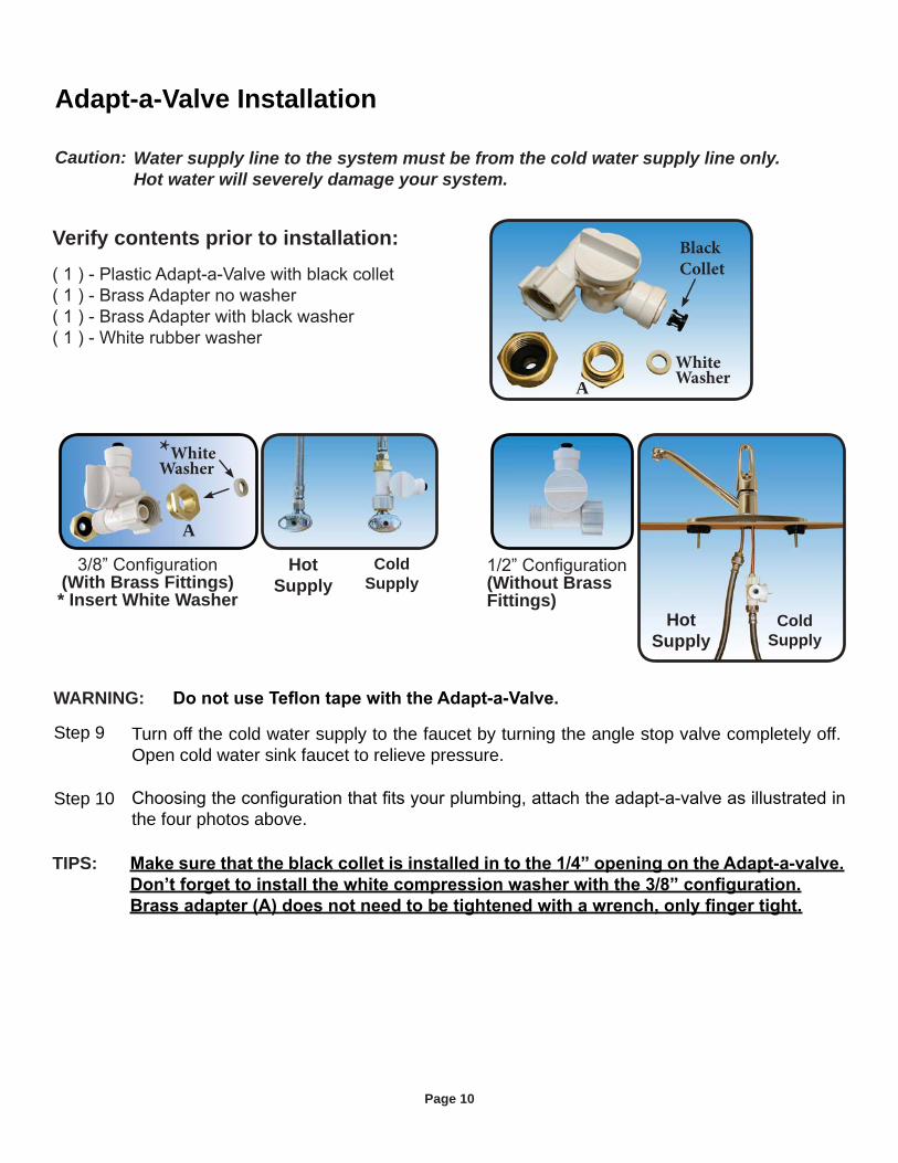
Turn off the cold water supply to the faucet by turning the angle stop valve completely off. Open cold water sink faucet to relieve pressure.
Step 9
Step 10the four photos above.
Adapt-a-Valve Installation
WARNING:
Caution: Water supply line to the system must be from the cold water supply line only. Hot water will severely damage your system.
(With Brass Fittings)* Insert White Washer
(Without Brass Fittings)
*WhiteWasher
HotSupply
ColdSupply
HotSupply
ColdSupply
Verify contents prior to installation: Black Collet
A
TIPS:
AWhiteWasher

Page 11
Drain Saddle Installation
Step 11
Step 12
Step 13 The drain saddle must be installed at least 1 ½” above the nutof the P-Trap elbow or cross bar from the garbage disposal to
installation. Take extreme caution to only drill through one sideof the drain pipe.
The small square black foam gasket with a circle cut out of the middle must be applied to the inside of the drain saddle. Remove sticky tape backing and stick to the drain saddle as shown.
1 Semicircle bracket with openingGather the pieces of the drain saddle:
Caution: Do not over tighten the screws. It may crack the drain saddle.
If you have a garbage disposal, do not install the drain saddle near it. Installation of the drain saddle must be either above the garbage disposal, or if a second sink drain is available, install it above the cross bar on the second drain. Installation of the drain saddle near a garbage disposal may cause the drain line to plug. If no other installation of drain line is available, Premier offers drain line installation kit (part number 164020) that can be used with garbage disposals.
Caution:
The black 3/8” drain tube must be as SHORT and STRAIGHT as possible to the drain saddle, making a downward slope from faucet to drain saddle to allow for proper drainage. This is a gravity fed line and if there is any bend or dip in the tube, the rinse
gap hole in the back of the faucet.
IMPORTANT:
Measure the 3/8” black tube from faucet to the drain saddle on the drain pipe and make a straight cut to the correct length.
saddle by pushing the tube all the way to the tube stop.Step 16
Step 15
Assemble the drain saddle around the drain pipe and align drain
step - you may use a small screwdriver to feed through the drain
screw driver tighten the drain saddle bolts evenly and securely onboth sides.
Step 14

Page 12
Reverse Osmosis Module MountingStep 18 Determine best location for the RO module to be mounted to allow
bracket, mark the location for the mounting screws on the cabinet
the cabinet at the marked location. Hang the module on the screws using the mounting holes in the bracket
Green Tube ConnectionStep 17
on the plastic water feed valve making sure the tube is pushed in all the way to the tube stop.
Step 19
Red 1/4” Tube Connection (from faucet)
the 1/4” red tubing from the faucet and the 1/4” red tubing from the RO membrane housing would join together comfortably. Cut red tube
tube from RO faucet in one end of the white plastic union and the
wrench to tighten both of the white plastic nuts securely.
Green Tube
Tank Ball Valve Installation
onto the stainless steel connector on the tank.
Note: Do not over-tighten plastic connections.
Step 20
Step 21
Blue Tube Connection (From The Tank to Shut off Valve)
slip the blue tube through the white compression nut, hand tighten the white nut and add 1/4 turn with a wrench.
Step 22
Note:

Page 13
Start up Instructions
If you have connected your RO system to a refrigerator / ice maker, make sure the ice maker is
have an in-line valve installed before the ice maker so it can easily be closed to prevent water
this step two more times. The fourth tank can be used for drinking.
Step 4
Turn on the incoming cold water at the angle stop valve and the
Step 3
Step 2
Note:
Step 1
temperature and water pressure.
Flushing of the tank 3 times is only necessary during the initial startup and after replacing the membrane.
Note:
Note:
ON

Page 14
6 Month System Maintenance
Step 1
Step 3may take a few minutes.
Items needed:
Note: -
Turn off the incoming water supply to the RO at the feed water valve.
Close the tank Ball valve.
Step 2
nd rd housing
Step 4
with water. Check O-rings and lubricate with water soluble lubricant. KY Jelly® or other water based lubricants may be used. Petroleum based lubricants (such as Vaseline®) must not be used.
Step 5
rings to make sure they are still in place. *Caution:
Note: If you own a four stage system it will not have the third stage. A four stage system has two vertical housings instead of three.
Step 6
Step 7
Step 8 Turn on the water supply to the unit at adapt-a-valve.
Step 10
Step 9
Close the RO faucet and open tank ball valve.
*
Loosen
OFF

Page 15
Annual Maintenance
NOTICE: Sanitizing of unit is recommended - RO storage tank must be drained.
NOTICE: If not sanitizing the system, skip to step 11
-
DANGER!
continue rinsing eye. Call a poison control center or doctor for treatment advice.
system by turning the adapt-a-valve counter clockwise. Let the unit fill with water
Step 5: Let the system sit idle for 1 minute
Step 6: Drain the system completely
draining the system again.
Step 8: Turn off the incoming water at the adapt-a-valve and open the faucet to make sure all the water has been drained
Step 9: Open the membrane housing and re-install the RO membrane while making sure not to
tubing.
Step 10: Remove filter housings Stage 1, 2 and 3 and empty water.NOTICE: Before re-installing the filter bowls back on to the system , check O-rings to
make sure they are still in place and lubricate with water soluble lubricant.
and re-install housing.
re-install housing. Step 13: The final in-line filter is located on the blue tube between the storage tank and the RO
faucet. Remove it by loosening the compression fittings on both ends of the filter and
SAN
ITAT
ION
STE
PS

Page 16
Membranes have a life expectancy between 2 and 5 years, depending on the incoming water conditions and the amount the RO system is used. This reverse osmosis membrane is critical for
verify that the system is performing satisfactorily.
at any time you notice a reduction in water production or an unpleasant taste in the reverse osmosis water, it could be time to replace the membrane. Premier recommends replacing the membrane when TDS reduction falls below 75%.
NOTE: A water sample may be sent to Premier for a free diagnosis of your membrane performance. To send a water sample, use two (2) clean containers and fill ½ cup of tap water in one container and ½ cup of reverse osmosis water in 2nd container. Clearly label each sample. Send the samples to the address listed on the cover of this manual attention “Water Samples”. Premier will test the water and mail or call you with the results.
Step 1: Turn off the incoming water supply to the RO system.
it is completely empty.Step 3: Disconnect the green tube from the elbow on the end cap of the
membrane housing.Removing the membrane:Step 4: Remove the end cap from the membrane housing by turning it
counter clockwise to loosen.
and pull firmly on the membrane to remove from the housing and discard.
Installing the membrane:Step 6: Lubricate the O-rings on the new membrane with a water soluble
O-rings on the PVC tube first into the housing.Step 7: Once membrane has been inserted into the housing you must take your thumbs and give
a firm push to properly seat the membrane. Replace membrane housing cap and tighten.Step 8: Re-attach the green tube to the elbow fitting on the end cap of the membrane housing.
Membrane Replacement
-
reduction performance.
the RO storage tank.TIP: This is a good time to check the air pressure in your storage tank. For instruc-
tions please see page 17.
directions.

Page 17
Once all water in the tank is purged, check air pressure using an air pressure gauge, it should
Check Air Pressure in the Tank
Important:
Step 3
Check air pressure only when tank is empty of water!
Step 1 Turn off the incoming water supply to the RO.
it is completely empty.Step 2
Check air pressure in the storage tank when you notice a decrease in available water from the RO system. Air can be added with a bicycle pump using the schrader valve that is located on the lower side of the tank behind the blue plastic cap.
Tip: When water from the RO faucet slows to a trickle, with the faucet still in the open posi-tion, you may add air to the tank to purge any left over water, this will ensure that the tank is completely empty.
Procedure for Extended Non-Use (More than 2 months)
a sealed plastic bag with the RO water saved earlier and store in your refrigerator.
startup procedure on page 13.
Step 4

Page 18
TROUBLE SHOOTINGProblem Cause Solution
Premier sells a booster pump if home water pressure is low. Make sure water supply is turned on and feed water valve is all the way open. Crimps in tubing Check tubing and straighten or replace as necessary.
start up of the RO system. This milky look will
times.
running, unit will not shut off Crimp in supply tube Check tubing and straighten or repair as necessary.
High water pressure Check incoming water pressure to make sure it does not exceed 80 psi. A pressure relief valve may be necessary. High pressure in Tank Empty storage tank of water. Set tank air pressure between 5-7 psi. See previous page.
tank pressure should be 5-7 psi. See page 78.
vent hole or noise from in drain line Straighten all drain lines. Clear blockage. Cut off any drain. Excess tubing
Drain tube clogged Caused from dishwasher or garbage disposal. Disconnect the 3/8” black line at the drain, clean the 3/8” black line out with a wire, then reconnect. Blowing air through the line will not always remove the clog.
storage tank incoming water pressure and/or temperature can drastically reduce production rate.
To much air in tank Tank air pressure should be 5-7 psi when empty of water.
Check only when tank is empty of water. See previous page.
Replace the O-ring if necessary. Then lubricate it and
tank pressure should be 5-7 psi. See page 17.

Page 19
Description Change time Frame
Depending on water chemistry, water temperature, and water pressure Premier’s R.O. Systems production and performance will vary.
the system that is available to the user as reverse osmosis treated water when the system is operated without a storage tank or when the storage tank is bypassed. There is an average of 4 gallons of reject water for every 1 gallon of product water produced.REFER TO OWNER’S INSTALLATION/SERVICE MANUAL FOR FURTHER MAINTENANCE REQUIREMENTS AND WARRANTY INFORMATION.
1. System to be used with municipal or well water sources treated and tested on regular basis to insure bacteriological safe quality. DO NOT use with water that
Watts Premier 8716 W Ludlow Drive Suite #1
Peoria, AZ 85381
5 SV Deluxe, CRO-TFM-5SV, Ultra 5 and Pur-Tek, Premier 25, Premier RO-4, Premier RO-5, RO-TFM-4SV, RO-TFM-5SV
less. This system reduces pentavalent arsenic, but may not remove other forms of arsenic. This system is to be used on water supplies containing a detectable free chlorine residual at the system inlet or on water supplies that have been demonstrated to contain only pentavalent arsenic. Treatment with chloramine (combined
Sheet for further information. (mg/L) (mg/L) mg/L concentration concentration mg/L mg/L
* All Prices Subject to change without notice

Page 20
Public water utilities must have their water tested for arsenic. You can obtain the results from
well, you will need to have the water evaluated. The local health department or the state
combination of both. Although both forms of arsenic are potentially hazardous to your health, trivalent arsenic is considered more harmful than pentavalent arsenic.
RO systems are very effective at removing pentavalent arsenic. A free chlorine residual will rapidly convert trivalent arsenic to pentavalent arsenic. Other water treatment chemicals such as ozone and potassium permanganate will also change trivalent arsenic to pentavalent
arsenic to pentavalent arsenic, may not convert all the trivalent arsenic in to pentavalent
chlorine or combined chlorine is used in the water system.
This Premier reverse osmosis system is designed to remove up to 98% of pentavalent arsenic.
the independent laboratory standard testing conditions Premier has conducted additional
reducing up to 67% of trivalent arsenic from the drinking water.
The RO membrane component of this Premier reverse osmosis system must be maintained
ordering information can be found in the installation/operation manual maintenance section, by phone at 1-800-752-5582 or online www.premierh2o.com
Arsenic Fact Sheet

Page 21
Service RecordDate of Purchase:__________ Date of Install:___________ Installed by:__________________
NOTES:
Date 1st stageSediment(6 months)
2 nd stageCarbon(6 months)
3rd stageCarbon(6 months)
Final FilterCarbon(1 year)
TFMMembrane(2-5 years)

Page 22
Limited WarrantyWHAT YOUR WARRANTY COVERS:If any part of your Reverse Osmosis System is defective in workmanship (excluding replaceable filters and membranes), return unit after obtaining a return authorization (see below), less tank, within 1 year of original retail purchase, Watts Premier will repair or, at Watts Premier’s option, replace the system at no charge.
HOW TO OBTAIN WARRANTY SERVICE:For warranty service, call 1-800-752-5582 for documentation and a return authorization number. Once the return authorization number has been created, ship your Reverse Osmosis unit (less tank) to our factory, freight and insurance prepaid, with proof of date of original purchase. Include a note stating the problem experienced and include your name, address and your return authorization number. No returns will be accepted without the proper return authorization number. Watts Premier will repair it, or replace it, and ship it back to you prepaid.
WHAT THIS WARRANTY DOES NOT COVER:This warranty does not cover defects resulting from improper installation, (contrary to Watts Premier’s printed instructions), from abuse, misuse, misapplication, improper maintenance, neglect, alteration, accidents, casualties, fire, flood, freezing, environmental factors, water pressure spikes or other such acts of God.
This warranty will be void if defects occur due to failure to observe the following conditions:1. The Reverse Osmosis System must be hooked up to a potable municipal or well cold water supply.2. The hardness of the water should not exceed 10 grains per gallon, or 170 ppm.3. Maximum incoming iron must be less than 0.2 ppm.4. The pH of the water must not be lower than 2 or higher than 11.5. The incoming water pressure must be between 40 and 85 pounds per square inch.6. Incoming water to the RO cannot exceed 105 degrees F (40 degrees C.)7. Incoming TDS/Total Dissolved Solids not to exceed 1800 ppm.8. Do not use with water that is micro biologically unsafe or of unknown quality without 9. adequate disinfection before or after the system.
This warranty does not cover any equipment that is relocated from the site of its original installation. This warranty does not cover any charges incurred due to professional installation. This warranty does not cover any equipment that is installed or used outside the United States of America and Canada.
LIMITATIONS AND EXCLUSIONS:WATTS PREMIER WILL NOT BE RESPONSIBLE FOR ANY IMPLIED WARRANTIES, INCLUDING THOSE OF MERCHANTABILITY AND FITNESS FOR A PARTICULAR PURPOSE. WATTS PREMIER WILL NOT BE RESPONSIBLE FOR ANY INCIDENTAL OR CONSEQUENTIAL DAMAGES, INCLUDING TRAVEL EXPENSE, TELEPHONE CHARGES, LOSS OF REVENUE, LOSS OF TIME, INCONVENIENCE, LOSS OF USE OF THE EQUIPMENT, AND DAMAGE CAUSED BY THIS EQUIPMENT AND ITS FAILURE TO FUNCTION PROPERLY. THIS WARRANTY SETS FORTH ALL OF WATTS PREMIER’S RESPONSIBILITIES REGARDING THIS EQUIPMENT.
OTHER CONDITIONS:If Watts Premier chooses to replace the equipment, may replace it with reconditioned equipment. Parts used in repairing or replacing the equipment will be warranted for 90 days from the date the equipment is returned to you or for the remainder of the original warranty period, whichever is longer. This warranty is not assignable or transferable.
YOUR RIGHTS UNDER STATE LAW:Some states do not allow limitations on how long an implied warranty lasts, and some states do not allow the exclusion or limitation of incidental or consequential damages, so the above limitations or exclusions may not apply. This warranty gives you specific legal rights, and you may have other legal rights which vary from state to state.
WARNING: This product contains chemicals known to the State of California to cause cancer and birth defects or other reproductive harm. For more information: www.watts.com/prop65
REV 1629