
RNG110 Installation Guide Issue 1 - Support Home Page INSTALLER’S MANUAL (501-3438010) 4 SAFETY...
28
INSTALLATION GUIDE Pace RNG110 BRINGING TECHNOLOGY HOME www.pace.com
Transcript of RNG110 Installation Guide Issue 1 - Support Home Page INSTALLER’S MANUAL (501-3438010) 4 SAFETY...

INSTALLATION GUIDE Pace RNG110
BRINGING TECHNOLOGY HOME www.pace.com
2RNG110 INSTALLER’S MANUAL (501-3438010)
CONTENTS
This manual describes some on-screen displays such as menus. These may change in the future, if the set-top’s software is updated over the cable. However, the way that you use the menus will remain similar to the way described in this manual.
This product incorporates copyright protection technology that is protected by U.S. patents and other intellectual property rights. Use of this copyright protection technology must be authorized by Macrovision, and is intended for home and other limited pay-per-view uses only unless otherwise authorized by Macrovision. Reverse engineering or disassembly is prohibited.
Manufactured under license from Dolby Laboratories. Dolby and the double-D symbol are trademarks of Dolby Laboratories.
HDMI, the HDMI Logo and High-Definition Multimedia Interface are trademarks or registered trademarks of HDMI Licensing LLC.
Other trademarks listed herein are the property of their respective owners.
SAFETY INFORMATION .......................................................................................................................................3
OVERVIEW ...........................................................................................................................................................6
The set-top’s front panel ......................................................................................................................................6
REAR PANEL ........................................................................................................................................................7
CONNECTING THE EQUIPMENT .........................................................................................................................8Getting the cables ready .................................................................................................................................8Connecting a remote “eye” (IR receiver) .......................................................................................................8Choosing the best setup .................................................................................................................................9Setup A - HDTV only (using HDMI or separate video and audio connections) ........................................ 10Setup B - HDTV with optional home theater (using a single video and audio connection) ..................... 11Setup C - HDTV and home theater (using component video and digital audio connections) ................. 12Setup D - SDTV only (using composite video and audio connections) .................................................... 13Setup E - SDTV and VCR/DVD recorder (using composite video and audio connections) ..................... 14Setup F - SDTV, VCR/DVD recorder, and home theater (using composite video and audio connections) ..15Connecting the power supply unit to the set-top ....................................................................................... 16Connecting equipment to the wall AC outlets ............................................................................................. 16Lightning storms .......................................................................................................................................... 16
OPERATING THE SET-TOP ............................................................................................................................... 17Turning the set-top on and off ..................................................................................................................... 17Using the remote control ............................................................................................................................. 17Displaying a picture on the HDTV screen ................................................................................................... 18Setting up subtitles ...................................................................................................................................... 18
MAKING USER SETTINGS ................................................................................................................................ 19About User Settings ..................................................................................................................................... 19About the TV Aspect Ratio........................................................................................................................... 19About TV Display Capability (resolution settings) ...................................................................................... 20Setting Auto Pillarbox .................................................................................................................................. 21Making Closed Caption Settings ................................................................................................................. 22Making Front-Panel Settings ....................................................................................................................... 23Changing HDMI Settings ............................................................................................................................. 23Removing the User Settings menus ........................................................................................................... 23Restoring the factory default settings ......................................................................................................... 24
USING ZOOM AND THE SETUP MENUS ......................................................................................................... 25Using Zoom to change the picture .............................................................................................................. 25Using the setup menus ................................................................................................................................ 25
DISPLAYING DIAGNOSTIC SCREENS ............................................................................................................. 26
TROUBLESHOOTING ........................................................................................................................................ 27

3RNG110 INSTALLER’S MANUAL (501-3438010)
SAFETY INFORMATION
This digital set-top has been manufactured and tested with your safety in mind. However, improper use can result in potential electric shock or fire hazards. To avoid defeating the safeguards that have been built into the set-top, please observe the precautions discussed in this document.
Warnings on the power supply unit
The lightning flash with arrowhead symbol, within a triangle, is intended to alert you to the presence of uninsulated “dangerous” voltages within the power supply unit’s enclosure that may be of sufficient magnitude to constitute a risk of electric shock to persons.
The exclamation point within a triangle is intended to alert you to the presence of important instructions in the literature accompanying the set-top.
Other warningsTo reduce the risk of electric shock, do not remove the cover of the set-top. There are no user-serviceable parts inside it.
Do not perform any servicing unless you are qualified to do so. Refer all servicing to qualified service personnel. Servicing the set-top yourself will invalidate the warranty.
On the rear panel of the set-top there is a tamper-evident label that states ‘Warranty void if broken or removed’.
To reduce the risk of fire or electric shock, do not expose this set-top to rain or moisture.
InstallationThe installation of the set-top should be carried out by a qualified installer and should conform to local codes.
Note to the installerThis reminder is provided to call the attention of the cable-TV-system installer to Section 820 of the National Electrical Code (USA), which provides guidelines for proper grounding and, in particular, specifies that the cable ground shall be connected to the grounding system of the building, as close to the point of cable entry as is practical.
IMPORTANT SAFETY INSTRUCTIONSBefore you install or use the apparatus, you must read and understand these Important Safety Instructions. At all times when using the apparatus you must follow these Important Safety Instructions to reduce the risk of fire, electrical shock and injury to persons.
1. Read these instructions.
2. Keep these instructions.
3. Heed all warnings.
4. Follow all instructions.
5. Do not use this apparatus near water.
6. Clean only with dry cloth.
7. Do not block any ventilation openings. Install in accordance with the manufacturer’s instructions.
8. Do not install near any heat sources such as radiators, heat registers, stoves, or other apparatus (including amplifiers) that produce heat.
9. Do not defeat the safety purpose of the polarized or grounding-type plug. A polarized plug has two blades with one wider than the other. A grounding type plug has two blades and a third grounding prong. The wide blade or the third prong are provided for your safety. If the provided plug does not fit into the outlet, consult an electrician for replacement of the obsolete outlet.
10. Protect the power cord from being walked on or pinched particularly at plugs, convenience receptacles, and the point where they exit from the apparatus.
11. Only use attachments/accessories specified by the manufacturer.
12. Use only with the cart, stand, tripod, bracket, or table specified by the manufacturer, or sold with the apparatus. When a cart is used, use caution when moving the cart/apparatus combination to avoid injury from tip-over.
13. Unplug this apparatus during lightning storms or when unused for long periods of time.
14. Refer all servicing to qualified service personnel. Servicing is required when the apparatus has been damaged in any way, such as power-supply cord or plug is damaged, liquid has been spilled or objects have fallen into the apparatus, the apparatus has been exposed to rain or moisture, does not operate normally, or has been dropped.
Service address: Pace Americas Inc. 3701 FAU Boulevard, Suite 200, Boca Raton, Florida 33431 U.S.A.
RISK OF ELECTRIC SHOCKDO NOT OPEN
CAUTION

4RNG110 INSTALLER’S MANUAL (501-3438010)
SAFETY INFORMATION (cont.)
In addition to the Important Safety Instructions, please read the Safety Information below.
Power sourcesThe model number, serial number, and electrical rating of this set-top are on a label on its base.
You must operate the set-top only from the type of power source indicated on the marking label. If you are not sure of the type of power supply to the home, consult the dealer or local power company. If you move the set-top between locations at different temperatures, allow it to reach room temperature before you apply power to it.
OverloadingDo not overload wall AC outlets, extension cords or other power outlets as this can result in a risk of fire or electric shock.
LightningFor added protection for the set-top during a lightning storm, or when it is left unattended and unused for long periods of time, disconnect the set-top from the power supply and disconnect the cable system from the set-top. See also item 13 in the Important Safety Instructions.
Ambient temperature
The operating temperature range of the set-top is 32-104°F. If the ambient temperature around the set-top falls outside this range, you must correct this in order for the set-top to work correctly and safely. For example, if the temperature is too high, make sure there is sufficient ventilation (see below) and that the set-top is not directly on top of or underneath other equipment.
Ventilation
Slots and openings in the casing of the set-top are provided for ventilation, to ensure reliable operation of the set-top and to protect it from overheating.
• Neverblocktheventilationopeningsbyplacingtheset-toponabed,sofa, rug, or other similar surface. Place it on a hard, flat surface.
• Nevercovertheventilationopeningswithitemssuchasnewspapers,table-cloths, or curtains.
• Youcanplacetheset-topnearotherconsumerelectronicsdevices,suchas stereo amplifiers or televisions, but you must not place it directly on top or underneath them.
• Donotplacetheset-topinabuilt-in installation such as a bookcase or rack unless proper ventilation is provided and you have adhered to the manufacturer’s instructions.
• Maintain a minimum distance of three inches around the set-top for sufficient ventilation.
See also item 7 in the Important Safety Instructions.
Water and moisture
Do not expose the set-top to rain or moisture, dripping or splashing, and ensure that no objects filled with liquids, such as vases, are placed on the set-top. See also item 5 in the Important Safety Instructions.
Entry of objects and liquidsNever push objects of any kind into the set-top through openings as they may touch dangerous voltage points or short-out parts that could result in fire or electric shock. Never spill liquid of any kind on the set-top.
TransportingMove the combination of set-top and cart with care. Quick stops, excessive force and uneven surfaces may cause the combination of set-top and cart to overturn. See also item 12 in the Important Safety Instructions.
Placement and mountingDo not place the set-top on an unstable or uneven surface. The set-top may fall, causing serious injury to a child or adult and serious damage to the set-top. If you mount the set-top, for example to a wall or ceiling, follow the manufacturer’s instructions and use a mounting accessory recommended by the manufacturer. See also item 12 in the Important Safety Instructions.
Risk of fire or scorchingNever place naked flame sources, such as lighted candles, on or adjacent to the set-top.
Replacement partsWhen replacement parts are required, be sure that the service technician has used replacement parts specified by the manufacturer or that have the same characteristics as the original part. Unauthorized substitutions may result in fire, electric shock or other hazards. See also item 14 in the Important Safety Instructions.
Safety checkUpon completion of any servicing or repairs to the set-top, ask the service technician to perform safety checks to determine that the set-top is in its proper operating condition. See also item 14 in the Important Safety Instructions.
SAVE THIS INFORMATION FOR FUTURE REFERENCE
3 inch3 inch3 inch

5RNG110 INSTALLER’S MANUAL (501-3438010)
SAFETY INFORMATION (cont.)
Safety aspects of connectionsFull details of the rear panel are on page 7.
ConnectingDo not connect the set-top (or any other equipment such as a TV or VCR) to the power supply until you have properly connected all the other cables.
The set-top is designed for use only with the supplied power supply unit.
On the power supply unit there is a label that specifies the correct AC power supply input for it. Do not connect the power supply unit to any supply other than this.
Always connect the 5 volt DC cord from the power supply unit to the set-top before you connect the power supply unit to the wall AC outlet.
DisconnectingTo disconnect power from the set-top, always remove its power supply unit from the AC mains supply (rather than disconnect the 5 volt cord from the set-top).
Therefore you must install the set-top near to the wall AC outlet, which should be easily accessible.
If you are in any doubt about the power supply cord, its plug or its connection, consult a qualified electrician.
The CABLE IN connector is designed for connection to a cable network only.
You must not connect any other equipment, such as a VCR, to this input.
POWER INPUT
The model number, serial number, and electrical rating of this set-top are on a label on its base.
Regulatory informationCAUTION: Do not attempt to modify the set-top without written authorization from the manufacturer. Unauthorized modification could void your authority to operate the set-top.
NOTE
The set-top has been tested and found to comply with the limits for a Class B digital device, pursuant to Part 15 of the FCC Rules. These limits are designed to provide reasonable protection against harmful interference in a residential installation. The set-top generates, uses and can radiate radio-frequency energy and, if not installed and used in accordance with the instructions, may cause harmful interference to radio communications.
However, there is no guarantee that interference will not occur in a particular installation. If the set-top does cause harmful interference to radio or television reception, which can be determined by turning the set-top off and on, you are encouraged to try to correct the interference by one or more of the following measures.
•Reorientorrelocatethereceivingantenna.
•Increasetheseparationbetweentheset-topandthereceiver.
•Connecttheset-toptoanoutletonacircuitdifferentfromthattowhich the receiver is connected.
•Consultyourdealeroranexperiencedradio/TVtechnicianforhelp.
5 volt power supply unit
AC power cord
5 volt cord

6RNG110 INSTALLER’S MANUAL (501-3438010)
OVERVIEW
The set-top’s front panel
POWER lightLights green when the set-top is on; not lighted when the set-top is in standby or is disconnected from the power supply
REMOTE lightLights green when the set-top is receiving a signal from the remote control
HD lightLights blue when the set-top is receiving High-Definition Television (HDTV) content
DATA lightLights yellow when the set-top is receiving data and when there is an unread message
• Readallthesafetyinformationonpages3through5.
• Familiarizeyourselfwiththefrontandrearpanelsoftheset-top(seebelowandpage7).
• Istheset-topinaTVcabinetwithclosednon-transparentdoorsorsomewhereelsewhereitsIR-receivewindowisblockedfromview? If so, connect a remote “eye” (IR receiver) (see page 8).
• Decidehowyouwanttoconnecttheset-top(andtowhichequipment)andlookatthetableonpage9toseewhichsetupyoushould use.
• Beawareofmenusettingsthatcouldaffectyourchoiceofsetup(seepage25).
• Connecttheequipmenttogetheraccordingtoyourchosensetup,butdonotyetconnectthepowercords(seepages10through15).
• Connectthepowercordsandturnontheequipment(seepages16and17).
• CheckthatyoucanseeapictureontheHDTV(seepage18).
• CheckwhethertheusersettingsareappropriatefortheTVbeingusedandchangethemifnecessary(seepages19through24).
• Anyproblems?Displaythediagnosticscreens(seepage26)andconsultthe“Troubleshooting”sectiononpage27.
7RNG110 INSTALLER’S MANUAL (501-3438010)
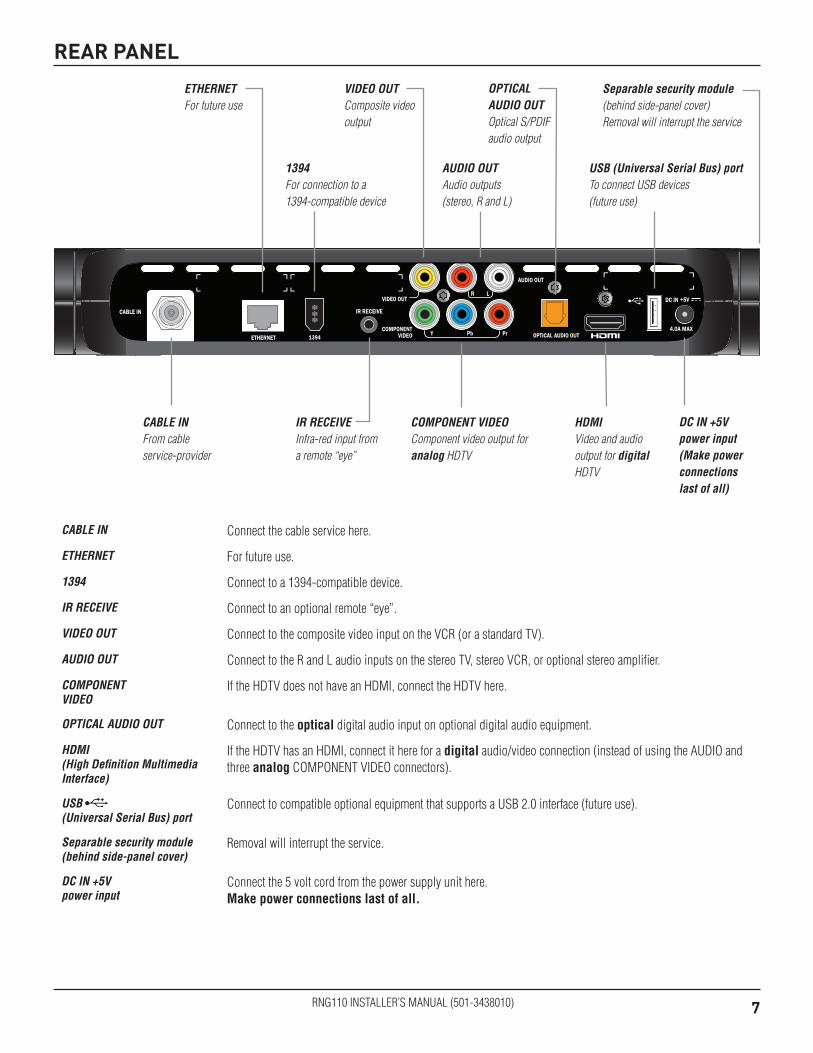
REAR PANEL
COMPONENT VIDEOComponent video output for analog HDTV
AUDIO OUTAudio outputs (stereo, R and L)
CABLE INFrom cable service-provider
VIDEO OUTComposite video output
DC IN +5V power input (Make power connections last of all)
OPTICAL AUDIO OUTOptical S/PDIF audio output
ETHERNETFor future use
HDMIVideo and audio output for digital HDTV
USB (Universal Serial Bus) portTo connect USB devices (future use)
IR RECEIVEInfra-red input from a remote “eye”
1394For connection to a 1394-compatible device
Separable security module (behind side-panel cover) Removal will interrupt the service
CABLE IN Connect the cable service here.
ETHERNET For future use.
1394 Connect to a 1394-compatible device.
IR RECEIVE Connect to an optional remote “eye”.
VIDEO OUT Connect to the composite video input on the VCR (or a standard TV).
AUDIO OUT Connect to the R and L audio inputs on the stereo TV, stereo VCR, or optional stereo amplifier.
COMPONENT VIDEO
If the HDTV does not have an HDMI, connect the HDTV here.
OPTICAL AUDIO OUT Connect to the optical digital audio input on optional digital audio equipment.
HDMI (High Definition Multimedia Interface)
If the HDTV has an HDMI, connect it here for a digitalaudio/videoconnection(insteadofusingtheAUDIOandthree analog COMPONENT VIDEO connectors).
USB (Universal Serial Bus) port
Connect to compatible optional equipment that supports a USB 2.0 interface (future use).
Separable security module (behind side-panel cover)
Removal will interrupt the service.
DC IN +5V power input
Connect the 5 volt cord from the power supply unit here. Make power connections last of all.

8RNG110 INSTALLER’S MANUAL (501-3438010)
CONNECTING THE EQUIPMENT
Getting the cables readyBelow is a list of cables (and their connectors) that are shown in the diagrams on pages 10 through 15, along with a key to how they are depicted in the diagrams. (Options are shown as dashed lines.)
Name Cable type Connector type Drawn as
Cable Input 75 Ω coaxial (RF cable) male F-type
HDMI Standard HDMI HDMI 19-pin type A
IEEE 1394 IEEE 1394 cableIEEE 1394 6-circuit (alpha) connector
Component video Video 75 Ω coaxial male RCA connector
Composite video Component video 75 Ω coaxial male RCA connector
Digital optical audio Digital audio optical opticalS/PDIF
L and R audio Stereo audio coaxial male RCA connector
Connecting a remote “eye” (IR receiver)You may need to install the set-top in an equipment closet with closed non-transparent doors or some other location where the remote-control sensor (IR-receive window) on the set-top’s front panel is blocked from view (for example, if the TV is wall-mounted). In that case, you need to connect a remote “eye” (IR receiver) to the set-top’s rear panel. The IR signals from the remote control can be received by the remote eye and they then reach the set-top through the remote eye’s cable. The remote eye is not supplied with the set-top.
1. Select a location for the remote eye. This will typically be on the top or side of the TV, but could be in a different, but convenient, location. Make sure that it is in a position where there is a clear path between the remote control and the remote eye.
2. Make sure that you can conveniently route the cable. The cable on the remote eye is approximately 10 feet long, so make sure that the location you have chosen is within 10 feet of the IR RECEIVE connector on the set-top’s rear panel.
3. Make sure the area where you will attach it is clean and dry.
4. A small adhesive patch is supplied with the remote eye. Remove the paper from one side of the patch and stick the patch to the back (larger, flat side) of the remote eye.
5. Remove the paper from the other side of the adhesive patch and stick the remote eye at the position you want. Make sure that the window at the curved end of the remote eye points towards the position from which the remote control will be operated.
6. Insert the 3.5 mm connector plug on the other end of the remote eye’s cable into the socket labeled “IR RECEIVE” on the rear panel of the set-top.
3.5 mm connector plug
adhesive patch
remote eye
front of HDTV

9RNG110 INSTALLER’S MANUAL (501-3438010)
CONNECTING THE EQUIPMENT (cont.)
Choosing the best setupIn order for you to view programs broadcast in high-definition, the set-top must be connected to a suitable HDTV or computer monitor. The set-top is also compatible with standard-definition TVs and VCRs.
Onthefollowingpagesarediagramsthatshowyouhowtoconnecttypicalequipment(HDTV,VCR/DVDrecorder, and home theater receiver) to the set-top. The connected items are shown individually and then in combination (see the tables below). Some of the connections may change when extra equipment is added. For example, when a you add a home theater receiver, some cables that previously went to the TV can, instead, go to the home theater receiver.
These setups make efficient use of the connectors on the set-top. However, depending on the other equipment and the connectors on it, you may choose to connect things differently.
These setups allow stereo recording and play-back of video tapes. You hear stereo sound from the home theater’s loudspeakers.
You can take advantage of the digital audio output from the set-top by connecting a suitable cable between the home theater receiver and the OPTICAL AUDIO OUT connector (as shown in the diagrams).
Setups using a high-definition television:
HDTV only (using HDMI or separate video and audio connections)
Setup A Page 10
HDTV with optional home theater (using a single video and audio connection)
Setup B Page 11
HDTV and home theater (using component video and digital audio connections)
Setup C Page 12
Setups using a standard-definition television:
SDTV only (using composite video and audio connections)
Setup D Page 13
SDTV and VCR/DVD recorder (using composite video and audio connections)
Setup E Page 14
SDTV, VCR/DVD recorder, and home theater (using composite video and audio connections)
Setup F Page 15
NOTES
How you set up the equipment may depend on the home theater receiver. For example, the optical and digital audio inputs may be associated with particular video inputs. Please see the home theater user information for further details.
WARNINGS
Do not connect the set-top (or any other equipment such as a TV or VCR) to the power supply until you have properly connected all the other cables.
Disconnect the set-top’s power supply unit from the AC power supply before you disconnect any other equipment from its rear panel.
The only way to disconnect the set-top from the AC power supply is to remove the power supply unit from the wall AC outlet (or switch the wall AC outlet switch, if present, to its OFF position). The set-top must therefore be installed near to the wall AC outlet, which should be easily accessible.
The cable input is designed for connection to a cable network only. You must not connect any other equipment, such as a VCR, to this input.
NOTECopy protection via an HDMI secure link
The HDMI link between the set-top and the HDTV should be a secure link. When the set-top is attached via an HDMI cable to an HDCP-compliant (High-bandwidth Digital Content Protection) HDTV, the HDTV and set-top negotiate a secure link, which allows the set-top to transmit full resolution video (picture) to the HDTV.
Not all HDTVs support HDCP. If the set-top is connected to an HDTV that does not support it, the following may be displayed:
Your HDTV does not support HDCP. Please use the YPbPr component connection to watch TV.
The HDMI output is then disabled, so no picture is transmitted from this connector. In that case, use the component video connectors to connect up.

10RNG110 INSTALLER’S MANUAL (501-3438010)
Setup A - HDTV only(using HDMI or separate video and audio connections)This is the most basic setup, with only an HDTV connected.
• If the HDTV has an HDMI connector, use an HDMI cable to connect it to the set-top’s HDMI.
• HDMI carries both high-resolution digital video and digital audio.
• Alternatively, if the HDTV does not have an HMDI connector, use component-video cables to connect the HDTV to the set-top.
• If component-video cables are used, in order to hear stereo sound you must also connect audio L and R cables between the AUDIO OUT connectors on the set-top and the audio-in connectors on the HDTV.
CONNECTING THE EQUIPMENT (cont.)
RF Cable TV HDMI or
Y, Pb, Pr Video & Audio L & R
RNG110
set-topHDTV
Cable TV
RF
LEFTAUDIO IN
RIGHTAUDIO IN
HDTV
CableInput
HDMI
RNG110
PbY PrCOMPONENT
VIDEO IN
HDMI
Component video
L and R audio
- OR -
+

11RNG110 INSTALLER’S MANUAL (501-3438010)
Setup B - HDTV with optional home theater(using a single video and audio connection)This is the most basic setup, with the addition of an optional home theater.
• If the set-top and HDTV have HDMI connectors, use an HDMI cable to connect it to the set-top’s HDMI.
• HDMI carries both high-resolution digital video and digital audio.
• To enhance the sound, you can connect a home theater. Use HDMI cables to connect the set-top to the home theater and the home theater to the HDTV. The home theater receives the audio signal through the HDMI connection.
• Alternatively, if the HDTV does not have an HMDI connector, use an IEEE 1394 cable to connect the HDTV to the set-top. IEEE 1394 carries both high-resolution digital video and digital audio.
CONNECTING THE EQUIPMENT (cont.)
RF Cable TV
HD
MI
HDMI or IEEE 1394RNG110
set-top
Home
Theater
HDTV Cable TV
RF
HDMI
Home Theater
HDTV
CableInput
HDMI
HDMI
1394
RNG110
IN
OUT
HDMI
- OR -
IEEE 1394

12RNG110 INSTALLER’S MANUAL (501-3438010)
Setup C - HDTV and home theater(using component video and digital audio connections)This is the most basic setup using component video, with only an HDTV and home theater connected.
• The set-top has component-video connectors as well as an HDMI.
• Use component-video cables to connect the set-top to the home theater and the home theater to the HDTV. In this case, to be able to hear audio you must use a separate audio connection, as shown.
• Theset-tophasanS/PDIFoutputlabeledOPTICALAUDIOOUT;thisprovidesthebestqualityaudio.
• IfthehometheaterhasanS/PDIFinput,connectittotheset-top’sOPTICALAUDIOOUTconnector;thisprovides the best quality audio.
• Alternatively, you can connect the home theater to the set-top’s AUDIO OUT connectors using audio L and R cables.
CONNECTING THE EQUIPMENT (cont.)
RF Cable TV RNG110
set-topHDTV
Cable TV
RF Y, Pb, Pr VideoY, Pb, Pr Video & Digtal Audio
Home
Theater
LEFTAUDIO
IN
RIGHTAUDIO
INDIGITAL OPTICALAUDIO IN
PbY Pr
HDTV
CableInput
RNG110
Home Theater
COMPONENT VIDEO IN
PbY Pr
COMPONENT VIDEO OUT
PbY Pr
COMPONENT VIDEO IN
Component video
L and R audio
- OR -
+
Digital optical audio

13RNG110 INSTALLER’S MANUAL (501-3438010)
Setup D - SDTV only(using composite video and audio connections)This is the most basic standard-definition setup using composite video.
• Use a composite-video cable to connect the set-top to the SDTV.
• In this case, to be able to hear audio you must use a separate audio connection, as shown.
• Connect audio L and R cables between the AUDIO OUT connectors on the set-top and the audio-in connectors on the SDTV.
CONNECTING THE EQUIPMENT (cont.)
RF Cable TV Composite Video & Audio L & RRNG110
set-topSDTV
Cable TV
RF
LEFTAUDIO IN
RIGHTAUDIO IN
CableInput
SDTV
RNG110
VIDEO IN
L and R audio
+Composite
video

14RNG110 INSTALLER’S MANUAL (501-3438010)
Setup E - SDTV and VCR/DVD recorder(using composite video and audio connections)In this setup, a VCR or DVD recorder is added to Setup D.
• Use composite-video cables to connect the set-top to the VCR or DVD recorder, and the VCR or DVD recorder to the SDTV.
• To be able to hear audio you must use separate audio connections, as shown.
• Connect audio L and R cables between the AUDIO OUT connectors on the set-top and the audio-in connectors on the VCR or DVD recorder.
• Connect audio L and R cables between the AUDIO OUT connectors on the VCR or DVD recorder and the audio-in connectors on the SDTV.
CONNECTING THE EQUIPMENT (cont.)
LEFTAUDIO
IN
RIGHTAUDIO
IN
SDTV
CableInput
RNG110
VCR/DVD Recorder
VIDEOIN LEFT
AUDIOIN
RIGHTAUDIO
IN
VIDEOIN
LEFTAUDIOOUT
RIGHTAUDIOOUT
VIDEOOUT
L and R audio
+Composite
video
RF Cable TVRNG110
set-topSDTV
Cable TV
RF Composite Video & Audio L & R Composite Video & Audio L & R
VCR/DVD
Recorder
NOTE
This diagram shows a video path from the set-top to a VCR to allow recording by the VCR. It shows a video path from the VCR to the TV to allow playback of videos. Video signals fed through a VCR may be affected by copyright protection systems, which can cause picture distortion on the TV. If you experience picture distortion of set-top programs, use a direct video path from the set-top to the TV. Remember to select the correct input on the TV.
15RNG110 INSTALLER’S MANUAL (501-3438010)
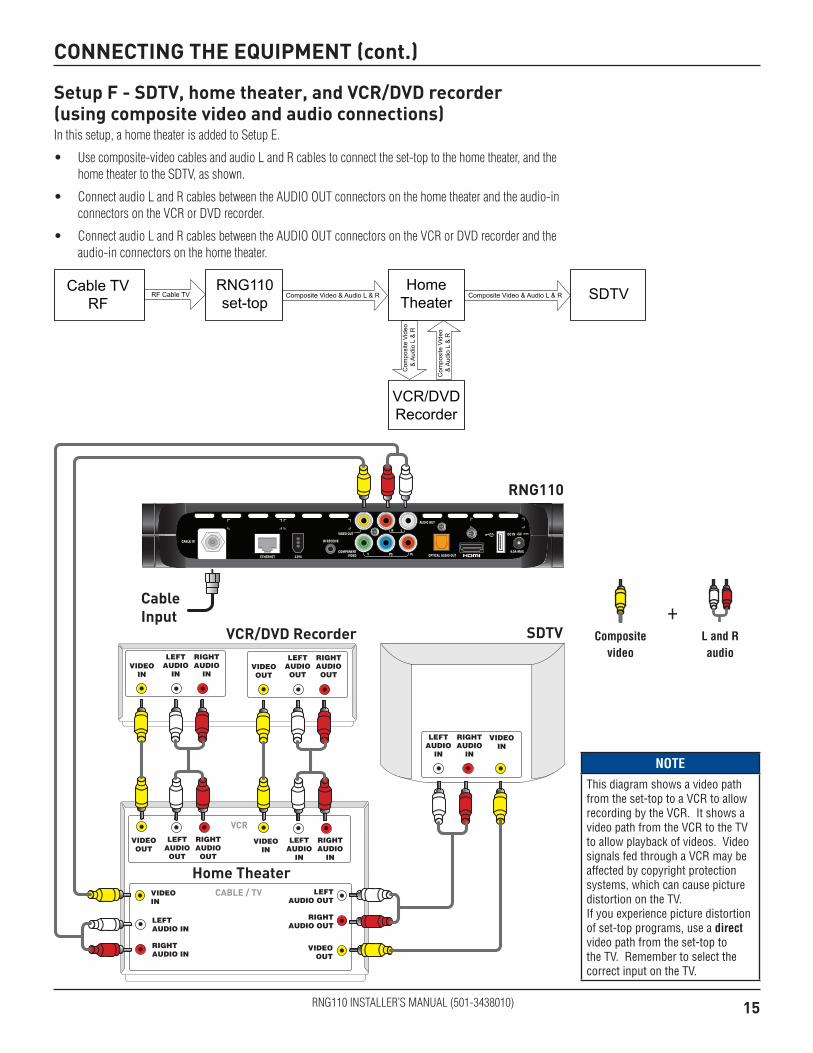
Setup F - SDTV, home theater, and VCR/DVD recorder(using composite video and audio connections)In this setup, a home theater is added to Setup E.
• Use composite-video cables and audio L and R cables to connect the set-top to the home theater, and the home theater to the SDTV, as shown.
• Connect audio L and R cables between the AUDIO OUT connectors on the home theater and the audio-in connectors on the VCR or DVD recorder.
• Connect audio L and R cables between the AUDIO OUT connectors on the VCR or DVD recorder and the audio-in connectors on the home theater.
CONNECTING THE EQUIPMENT (cont.)
SDTV
CableInput
RNG110
VCR/DVD Recorder
LEFTAUDIO
IN
RIGHTAUDIO
IN
LEFTAUDIO
IN
RIGHTAUDIO
IN
VIDEOIN
VIDEOIN
LEFTAUDIOOUT
RIGHTAUDIOOUT
VIDEOOUT
LEFTAUDIOOUT
RIGHTAUDIOOUT
VIDEOOUT
LEFTAUDIO
IN
RIGHTAUDIO
IN
VIDEOIN
LEFTAUDIO OUT
RIGHTAUDIO OUT
VIDEOOUT
LEFTAUDIO IN
RIGHTAUDIO IN
VIDEOIN
CABLE / TV
VCR
Home Theater
L and R audio
+Composite
video
RF Cable TVRNG110
set-topSDTV
Cable TV
RF
Home
TheaterComposite Video & Audio L & R Composite Video & Audio L & R
VCR/DVD
RecorderC
om
po
site
Vid
eo
& A
ud
io L
& R
Co
mp
osite
Vid
eo
& A
ud
io L
& R
NOTE
This diagram shows a video path from the set-top to a VCR to allow recording by the VCR. It shows a video path from the VCR to the TV to allow playback of videos. Video signals fed through a VCR may be affected by copyright protection systems, which can cause picture distortion on the TV. If you experience picture distortion of set-top programs, use a direct video path from the set-top to the TV. Remember to select the correct input on the TV.

16RNG110 INSTALLER’S MANUAL (501-3438010)
CONNECTING THE EQUIPMENT (cont.)
WARNINGS
Do not connect the set-top (or any other equipment such as a TV or VCR) to the power supply until you have properly connected all the other cables.
Do not defeat the safety purpose of the polarized plugs on power cords. A polarized plug has two blades with one wider than the other. This plug fits into the wall AC outlet in only one way; match the wide blade of the plug to the wide slot of the outlet.
Connecting the power supply unit to the set-topPlug the 5-volt cord from the power supply unit into the power input socket (labelled DC IN +5V) on the rear panel of your RNG110, then plug the power supply unit into the wall AC outlet using the power cord supplied.
Connecting equipment to the wall AC outletsConnect the set-top’s power supply unit, and the polarized plugs on the power cords from the TV, VCR, and any other equipment, into wall AC outlets. If these outlets have switches, switch them ON.
Lightning stormsDisconnect the set-top from the power supply during lightning storms. A lightning storm may affect the set-top, if it is on during the storm. It may appear that it has stopped working, but you can easily restore its operation as follows:
Unplug the set-top’s power supply unit from the wall AC outlet. Then plug this power supply unit in again at the wall AC outlet (and, if there is a switch by this outlet, switch it to its ON position).
Wall AC outlet

17RNG110 INSTALLER’S MANUAL (501-3438010)
OPERATING THE SET-TOP
Turning the set-top on and offAfter you have connected the set-top’s power supply unit to the wall AC outlet (and switched this outlet ON, if it has a switch), press the POWER button on the remote control to turn the set-top on (making sure the remote control is set to control the set-top). The POWER light on the set-top’s front panel should light up green, to show that the set-top is on.
To turn the set-top on or off at any time, press the POWER button on the remote control.
Never turn off the set-top by simply disconnecting it from the power supply. If you need to disconnect the set-top, turn off the set-top by pressing the POWER button on the remote control, so that the POWER light is switched off. Then wait a few seconds before disconnecting the power supply unit from the wall AC outlet.
Power Saving: To save power and money, and to reduce greenhouse gas emissions, turn off the set-top, using the POWER button on the remote control, when it is not in use.
Using the remote controlYour cable TV service-provider determines the digital channels, services, and screen information that you see on your TV when you use the set-top and its remote control.
Consult the information supplied by your cable service-provider for details on how to make the most of the digital cable services. Also read the operating instructions that are supplied with your remote control.
NOTES
IMPORTANT: Unless there is a lightning storm or the set-top’s users are away from their home for a long time, do not unplug the set-top’s power supply unit at the wall AC outlet (or do not switch it off there, if the outlet has a switch). The set-top cannot be updated with new features, through the cable, if it is disconnected from the power supply.
18RNG110 INSTALLER’S MANUAL (501-3438010)
Displaying a picture on the HDTV screenIf the set-top is connected to the HDTV’s component video or HDMI input and is turned on (the POWER light is green), but the HDTV does not initially display a picture from the set-top, the HDTV may not support the set-top’s current output resolution (for further details on resolutions, see page 20). You therefore need to change the set-top’s output resolution as follows:
1. First press the POWER button on the remote control (POWER light goes off), then press the MENU button.
2. Next, press the ZOOM button on the remote control (the button could be labeled ASPECT) until a picture appears. Each button-press changes the set-top’s output resolution, which also appears on the TV screen. After a few seconds, you should see the PACE USER SETTINGS menu.
3. Press the POWER button to remove this menu and return to normal viewing.
Setting up subtitlesSubtitles in various languages may be transmitted with TV programs. You can set up the set-top to display subtitles, when they are available. You can also set the preferred language for these subtitles. There is a choice of several languages, including English.
If you set subtitles to be “on”, they will be displayed in the preferred language only when subtitles in that language are transmitted with a program. For example, if you set subtitles to be “on” and in Spanish, but only French subtitles are transmitted with a particular program, you will see French subtitles for that program, not Spanish.
You can also turn on closed captions (see page 22) to give subtitles, but any subtitles you set up using this PACE SUBTITLE SETTINGS menu will take priority.
Selecting subtitles in the preferred language 1. Make sure that the set-top is turned on (the POWER light is green).
2. Press the POWER button on the remote control (POWER light goes off), then press the INFO button.
The PACE SUBTITLE SETTINGS menu appears on the TV screen (see right).
3. Press U or D to highlight “Subtitles”, then press OK/Select to turn them on or off.
4. Press U or D to highlight “Subtitle Language”, then use the OK/Select button to choose the language you want (the language changes each time you press OK/Select).
5. When you have finished making changes, press the POWER button to remove the PACE SUBTITLE SETTINGS menu and return to normal viewing.
OPERATING THE SET-TOP (cont.)
PACE SUBTITLE SETTINGS
Subtitles : OffSubtitle Language : English
Select[OK] Exit[POWER]
Video Format : 1080i
Current output resolution from the set-top
PACE USER SETTINGS
TV Aspect RatioTV Display CapabilityAuto PillarboxClosed CaptionsFront Panel SettingsHDMI SettingsRestore Defaults
Select[OK] Exit[POWER]

19RNG110 INSTALLER’S MANUAL (501-3438010)
MAKING USER SETTINGS
About User SettingsYou need to make the correct settings so that the set-top is compatible with the HDTV or TV. However, you may wish to change some settings, for example if you purchase a new HDTV. You can make the following settings and you can also reset them to the factory defaults.
• TVAspectRatio(thescreen’swidth-to-heightratio,orshape)
• TVDisplayCapability(screenresolution)
• AutoPillarbox
• ClosedCaptions
• FrontPanelSettings
• HDMISettings
You use the buttons on the remote control to make the settings using on-screen menus. However, until the set-top has been set up to match the display capability of the TV (see page 20), these menus may not be visible.
Putting the set-top into User Settings mode1. Make sure that the set-top is turned on (POWER light is green).
2. Press the POWER button on the remote control (POWER light goes off), then press the MENU button.You should see the PACE USER SETTINGS menu, shown right, on the TV screen.
3. When you have finished making changes (see pages 19 through 23), press the POWER button to remove the PACE USER SETTINGS menu and return to normal viewing.
About the TV Aspect RatioTheTVthatyouhaveconnectedtotheset-tophasanaspectratio(width-to-heightratio)of4:3(basic/standard)or 16:9 (widescreen). You must set the appropriate TV Aspect Ratio (4:3 or 16:9) on the set-top, so that it is compatible with the TV.
Setting the TV Aspect RatioIf you have not done so already, put the set-top into User Settings mode, as described above.
1. Press the U or D button on the remote control and highlight TV Aspect Ratio on the PACE USER SETTINGS menu.
2. Press the R button. The TV Aspect Ratio menu, shown below, appears on the TV screen. On the menu, the current setting (“4:3” or “16:9”) has > in front of it. Also, whenever the current setting is displayed, the DATA light will be lighted on the set-top’s front panel.
TV Aspect Ratio 4:3>16:9
3. Press the U or D button to highlight the TV Aspect Ratio you want.
4. Press the OK/Select button to confirm your choice and change to that TV Aspect Ratio.
5. Press the L button. The PACE USER SETTINGS menu reappears.
To continue making the settings, see the next section.
POWER light
PACE USER SETTINGS
TV Aspect RatioTV Display CapabilityAuto PillarboxClosed CaptionsFront Panel SettingsHDMI SettingsRestore Defaults
Select[OK] Exit[POWER]
4:3 standard TV, EDTV or HDTV
16:9 HDTV

20RNG110 INSTALLER’S MANUAL (501-3438010)
About TV Display Capability (resolution settings)• The set-top can transmit pictures to the TV in a range of resolutions (also called “Display Capabilities” - see
below for the settings available). Generally, higher screen resolutions give better quality pictures. However, the quality always depends on how the program was originally transmitted.
• Different TVs display different screen resolutions. For example, standard TVs display “480i”, EDTVs (Enhanced Definition TVs) display “480p”, and most HDTVs display “1080p”, “1080i” or “720p”. Many HDTVs will display at more than one resolution. For more information, see the information supplied with the HDTV.
You must make the appropriate TV Display Capability settings on the set-top, so that it is compatible with the TV. See below for full instructions.
In order to display the best picture every time, you must select every resolution that the TV is capable of displaying. This ensures that programs are displayed with minimum distortion.
There is a blue HD light on the set-top’s front panel that lights when the set-top is receiving high-definition content.
TV Display Capability settings• 480i is standard definition NTSC and is transmitted
in a 4:3 aspect ratio (see right).
• 480p is enhanced digital TV and can be transmitted in either a 4:3 or 16:9 aspect ratio.
• 720p,1080i, and 1080p are HDTV and are transmitted in a 16:9 aspect ratio (see right).
480i transmission: The aspect ratio is 4:3
1080i transmission: The aspect ratio is 16:9
NOTEWhen the HDTV is connected to the set-top via an HDMI connector, the set-top gets information from the HDTV about the HDTV’s display capability. The set-top uses this information to adjust its TV Display Capability settings.
The set-top also records the HDTV’s ID (identification), so that only one HDTV is supported at any one time. When the HDTV has updated the set-top’s TV Display Capability settings, you may change them if you wish. The changes will then be stored with the ID.
You can restore the set-top’s TV Display Capability settings to their factory values, as described on page 24. You can also restore the set-top to the settings that the HDTV has passed to the set-top. To do this you must first restore the factory settings while the HDMI cable is disconnected from the set-top, then reconnect the HDTV via the HDMI cable.
MAKING USER SETTINGS (cont.)
Changing the TV Display CapabilityIf you have not already done so, put the set-top into User Settings mode, as described on page 19.
1. Press the U or D button on the remote control and highlight TV Display Capability on the PACE USER SETTINGS menu.
2. Press the R button.The TV Display Capability menu appears on the TV screen. The available resolutions are: 1080p24*, 1080p30*, 1080i, 720p, 480p, and 480i.
TV Display Capability1080i : YES720p : NO480p : YES480i : YES1080p24 Pass : NO1080p30 Pass : NO
* NOTEIf the HDTV is 1080p-compliant and connected by HDMI, setting “1080p24 Pass” to YES causes 1080p/24 transmissions (at 24 frames per second) to be displayed at 1080p/24. Likewise, setting “1080p30 Pass” to YES causes 1080p/30 transmissions (at 30 frames per second) to be displayed at 1080p/30.
The HDMI-connected HDTV may report that it is not 1080p-compliant and set “1080p24 Pass” (or “1080p30 Pass”) to NO. In this case 1080p transmissions will be output at one of the other resolutions (1080i, 720p, 480p or 480i). If you override this NO setting and set YES, you may see nothing for 1080p transmissions.
If the HDTV is not connected by HDMI, “HDMI Cable Required” is displayed and you cannot set “1080p24 Pass” or “1080p30 Pass” to either YES or NO.
Transmissions at 480i, 480p, 720p or 1080i can never be output at 1080p.
3. Press the U or D button to highlight each resolution in turn and, for each one, press the OK/Select button if you wish to change the setting (the setting changes between “YES” and “NO” each time you press OK/Select).
If, at any stage in this process, the menu disappears from the screen, immediately press the OK/Select button to restore the menu.
4. When you are satisfied that all the TV resolutions are correct, press the L button. The PACE USER SETTINGS menu reappears.

21RNG110 INSTALLER’S MANUAL (501-3438010)
Further information about the TV Display CapabilityThe TV Display Capability settings relate to equipment that is connected to the HDMI and COMPONENT VIDEO OUT connectors because the settings control the output at those connectors. If equipment is connected via an HDMI cable, that equipment may also pass information back to the set-top, which may affect what settings are available.
Generally, the TV Display Capability settings do not affect equipment connected to the VIDEO OUT connector, because the output at this connector will always be the standard definition 480i.
Setting Auto PillarboxIf the TV is a 16:9 TV that does not automatically detect 4:3 transmissions (and therefore does not add black bars to the sides of the picture), then 4:3 transmissions may display “stretched” to fit the 16:9 screen. If you do not want this effect, you can set the set-top to add black bars to the 4:3 picture, so that it is transmitted to the TV at a 16:9 aspect ratio. See the example below.
MAKING USER SETTINGS (cont.)
4:3 transmission 16:9 TV with no automatic detection of 4:3,
Auto-pillarbox switched off
16:9 TV with no automatic detection of 4:3,
Auto-pillarbox switched on
Changing the Auto Pillarbox settingIf you have not done so already, put the set-top into User Settings mode, as described on page 19.
1. Press the U or D button on the remote control and highlight Auto Pillarbox on the PACE USER SETTINGS menu.
2. Press the R button. The Auto Pillarbox menu appears on the TV screen.
3. If you want to change the setting, press U or D. Press the OK/Select button to confirm the choice and change to the new setting.
4. Press the L button. The PACE USER SETTINGS menu reappears.
NOTE
16:9 picture in a 4:3 transmissionSometimes, 4:3 transmissions may contain a 16:9 picture, with black borders at the top and bottom. On a 16:9 TV, this may display with black borders all the way around the picture. To remove these borders, you can use the “Zoom function” button on your remote control (could be labeled ZOOM or ASPECT). See the example below. For more information about using “Zoom”, see page 25.
4:3 transmission 16:9 TV with no automatic detection of 4:3,
Auto-pillarbox switched off
16:9 TV with no automatic detection of 4:3,
Auto-pillarbox switched on
Use 'Zoom' to increase the picture size.(Note: the picture may lose somedefinition due to the expansion)
Auto Pillarbox YES>NO
> shows current setting

22RNG110 INSTALLER’S MANUAL (501-3438010)
Making Closed Caption SettingsClosed captioning is a means of displaying alerts and subtitles on the TV screen, superimposed on whatever you are watching. You can turn closed captions on or off, as required, and you can also change the closed captions’ appearance.
Turning closed captions on or offIf you have not done so already, put the set-top into User Settings mode, as described on page 19.
1. Press the U or D button on the remote control and highlight Closed Captions on the PACE USER SETTINGS menu.
2. To change the Closed Captions setting, press the R button. The Closed Captions menu appears (see right).
3. The current Closed Captions (CC) setting, either “ON” or “OFF” is highlighted on the menu.
4. If you want to change the setting, press the OK/Select button - the setting changes.
5. Press the L button. The PACE USER SETTINGS menu reappears.
To continue making the settings, see the next section.
Changing the closed captions’ appearanceIf you want to change the closed captions’ appearance, you can see the effect of your settings by looking at the example below the menu.
1. In the Closed Captions menu (see above), press the D button to highlight “Configure Captions”, then press OK/Select. The Configure Captions menu appears (see right).
2. Use the U and D arrows to highlight each option in turn. Use the OK/Select button to choose the setting you want (the setting changes each time you press OK/Select).
3 If you wish to reset all the Closed Caption settings to their default values (mainly Auto), press the D button to highlight “Reset to Defaults” in the menu, then press OK/Select.
4. When you have made all the changes you want to make, press L twice to redisplay the PACE USER SETTINGS menu.
Configure CaptionsSize : SmallFont : Style 1Character Color : WhiteCharacter Shading : AutoBackground Color : BlackBackground Shading : AutoStd Def CC : AutoHi Def CC : Service 1Reset to Defaults
Closed Caption Example
MAKING USER SETTINGS (cont.)
Closed CaptionsCC : OFFConfigure Captions

23RNG110 INSTALLER’S MANUAL (501-3438010)
Making Front-Panel SettingsYou can use the Front Panel Settings menu to set the brightness level of the front-panel lights when the set-top is being used (“Viewing Brightness”) and when it is switched off (“Standby Brightness”).
If you have not done so already, put the set-top into User Settings mode, as described on page 19.
1. Press the U or D button on the remote control and highlight Front Panel Settings on the PACE USER SETTINGS menu.
2. Press the R button. The Front Panel Settings menu, shown right, appears on the TV screen.
3. Press the U or D button to highlight “Standby Brightness” or “Viewing Brightness” as required.
4. Use the OK/Select button to choose the setting you want (the setting changes each time you press OK/Select): “Low”, “Std” (Standard), or “High”. Look at the dimming and brightening of the front-panel lights while you are making the settings, to see the effect of your selections.
5. When you have made all the changes you want to make, press L to redisplay the PACE USER SETTINGS menu.
Changing HDMI SettingsYou can use the HDMI Settings menu to choose an Audio Output Mode, and to enable or disable automatic detection of a newly connected HDTV (when using an HDMI cable).
If you have not done so already, put the set-top into User Settings mode, as described on page 19.
1. Press the U or D button on the remote control and highlight HDMI Settings on the PACE USER SETTINGS menu.
2. Press the R button. The HDMI Settings menu, shown right, appears.
3. Press the U or D button to highlight “Audio Output Mode” or “Disable Auto Detect” as required.
4. Use the OK/Select button to choose the setting you want (the setting changes each time you press OK/Select).
Audio Output Mode has three possible settings:
“Auto” (provides the audio format best suited to the connected equipment)
“L-PCM” (provides PCM audio only)
“Pass Through” (maintains the original incoming-audio format)
Disable Auto Detect is either “YES” or “NO”.
5. When you have made all the changes you want to make, press L to redisplay the PACE USER SETTINGS menu.
Removing the User Settings menusWhen you have finished making all the user settings you wish to make, press the POWER button to remove the PACE USER SETTINGS menu and return to normal viewing.
Front Panel SettingsStandby Brightness : StdViewing Brightness : High
HDMI SettingsAudio Output Mode : AutoDisable Auto Detect : NO
MAKING USER SETTINGS (cont.)

24RNG110 INSTALLER’S MANUAL (501-3438010)
Restoring the factory default settingsIf you wish, you can restore the user settings to their factory defaults. All the changes you have made will be lost and the settings will revert to those that were programmed in the factory.
The factory settings are:
USER/SUBTITLE SETTINGS menu item Options Factory default settingTV Aspect Ratio – 16:9
TV Display Capability 1080i 720p 480p 480i 1080p24 Pass 1080p30 Pass
Yes No Yes Yes No No
Auto Pillarbox – No
Closed Captions – Off
Configure Captions Various All Auto except Hi Def CC, which is Service 1
Front Panel Settings Standby Brightness Viewing Brightness
Std High
HDMI Settings Audio Output Mode Disable Auto Detect
Auto No
Subtitles – Off
Subtitle Language – English
If you have not done so already, put the set-top into User Settings mode, as described on page 19.
1. Press the U or D button on the remote control and highlight Restore Defaults on the PACE USER SETTINGS menu.
2. Press the R button. The message: “Restore Default. Press OK to confirm” appears on the TV screen. (If, at this stage, you no longer wish to restore the factory settings, press the L button.)
3. To confirm and restore the factory settings, press the OK/Select button.The factory settings are restored, and the PACE USER SETTINGS menu reappears.
4. If you want to continue changing the settings, see the sections from page 19 onwards. If you have finished changing the settings, press the POWER button. The set-top then switches on with the restored settings.
NOTES
If the set-top and HDTV are connected via a standard HDMI cable, the HDTV may pass information about the required settings back to the set-top (see page 20). If you wish to restore the set-top’s settings to those created by the HDTV, you must disconnect the HDMI cable from the set-top before you restore the factory default settings. When you reconnect the HDTV to the set-top via the HDMI cable, the HDTV will pass back the information again.
Always turn off the set-top, then disconnect the set-top’s power supply unit from the wall AC outlet before you connect or disconnect any other equipment to or from the set-top’s rear panel.
MAKING USER SETTINGS (cont.)

25RNG110 INSTALLER’S MANUAL (501-3438010)
Using Zoom to change the pictureMaking the appropriate TV Aspect Ratio and TV Display Capability settings (see pages 19 and 20) should ensure that the picture on the TV screen is not distorted (stretched or squashed) and that it fills as much of the screen as possible.
However, even if you have selected the correct settings, there may be times when a program appears with black borders either at the top and bottom or at the sides of the picture (or sometimes even all the way round the picture). This happens because the aspect ratio (shape) of the transmitted program does not match the aspect ratio of the HDTV, or because the transmitted programme includes black borders as part of the transmission (see right).
The remote control should have a “zoom function” button (could be labeled ZOOM or ASPECT), which you can use to change the TV picture until it appears as you want it to.
1. Press the “zoom function” button once to change the display.
2. Press it again to change the display again. Continue to press it in this way until the picture appears as you want it to.
Note: The effect that this button has on transmissions depends on the transmission itself. On some transmissions it may have no effect at all.
Using the setup menusIn addition to the user settings described on pages 19 through 23, setup menus may be available in the on-screen guide. These should be described in the information provided by the service-provider. There may also be on-screen information to explain these menus.
However, certain settings may affect how the set-top and TV work. See the table below for information about typical menu items and settings (they depend on which on-screen guide is running on the set-top, so may vary from those given below).
Item Options Settings NotesCable Box Setup Configuration Allows you to view the configuration of the
set-top.
Audio Default Audio Track
Channel Default, English, various other languages
Sets the language track that the set-top first attempts to use when tuning to a channel. “Channel Default” means the set-top uses the default audio track for the program. Selecting a language means it uses the corresponding language track, if available.
Optimal Stereo
Selecting this option enables the set-top to regulate the volume to minimize sudden changes in volume, for example during a commercial break.
Audio Output
TV Speakers, Stereo, Advanced
If you select “Advanced”, further settings are displayed, allowing you to set the Compression (to None, Light, or Heavy) and the Stereo Output (to Mono, Stereo or Matrix Stereo).
Screen position This allows you to adjust how the picture displays on the TV screen.
Other items and options may be available on these screens. The menus may be subject to change in the future, as the set-top advances with new technology.
USING ZOOM AND THE SETUP MENUS
A 4:3 transmission, with a 16:9 picture. Dark bars are added at the top and bottom of the transmission.
A 16:9 transmission, with a 4:3 picture in it. Dark bars are added at the sides of the transmission.

26RNG110 INSTALLER’S MANUAL (501-3438010)
DISPLAYING DIAGNOSTIC SCREENS
Displaying the Diagnostics Information screensThe Diagnostic Information screens provide “read-only” information about the configuration of the set-top. This includes information on, for example, addressing, memory, current channel, status information, etc.
First of all, make sure that the set-top is connected to the TV by HDMI or composite video (RCA) connections, and set the TV to its appropriate input.
Ensure the set-top is turned on (the POWER light on the front panel should be green).
To display the Diagnostics Information screens:Press and release the POWER button on the remote control, then immediately (within 2 seconds) press and release the OK/Select button on the remote control.
The DIAGNOSTICS DASHBOARD will then be displayed on the TV.
Note: The bottom line on the dashboard cycles between SW Version:, Unit Addr:, and Last Poll Ack:.
From the DIAGNOSTICS DASHBOARD, you can press the L button to display the DIAGNOSTICS MAIN MENU.
Use the L button to toggle between the DIAGNOSTICS DASHBOARD and DIAGNOSTICS MAIN MENU.
To use the Diagnostics Information screens:In both menus, use the U and D buttons on the remote control to move the on-screen arrow through the items, then press OK/Select or R to view more information in sub-menus. Or, instead, you can use the remote control to key in the 2-digit number of the sub-menu.
To remove a sub-menu and return to the preceding level, press the L button.
To remove the DIAGNOSTICS DASHBOARD (or DIAGNOSTICS MAIN MENU), and return to normal TV viewing, press the POWER button on the remote control twice.
27RNG110 INSTALLER’S MANUAL (501-3438010)
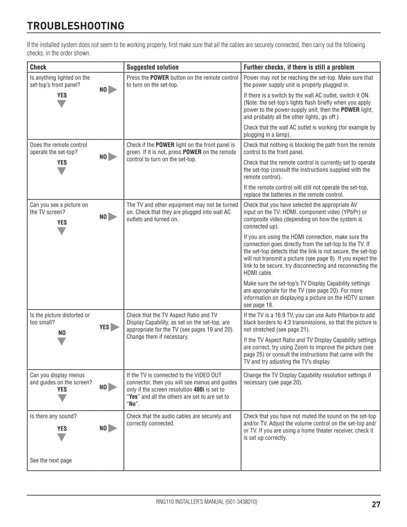
TROUBLESHOOTING
If the installed system does not seem to be working properly, first make sure that all the cables are securely connected, then carry out the following checks, in the order shown.
Check Suggested solution Further checks, if there is still a problem
Is anything lighted on the set-top’s front panel?
YES
D
NO RPress the POWER button on the remote control to turn on the set-top.
Power may not be reaching the set-top. Make sure that the power supply unit is properly plugged in.
If there is a switch by the wall AC outlet, switch it ON. (Note: the set-top’s lights flash briefly when you apply power to the power-supply unit, then the POWER light, and probably all the other lights, go off.)
Check that the wall AC outlet is working (for example by plugging in a lamp).
Does the remote control operate the set-top?
YES
D
NO RCheck if the POWER light on the front panel is green. If it is not, press POWER on the remote control to turn on the set-top.
Check that nothing is blocking the path from the remote control to the front panel.
Check that the remote control is currently set to operate the set-top (consult the instructions supplied with the remote control).
If the remote control will still not operate the set-top, replace the batteries in the remote control.
Can you see a picture on the TV screen?
YES
D
NO RThe TV and other equipment may not be turned on. Check that they are plugged into wall AC outlets and turned on.
Check that you have selected the appropriate AV input on the TV: HDMI, component video (YPbPr) or composite video (depending on how the system is connected up).
If you are using the HDMI connection, make sure the connection goes directly from the set-top to the TV. If the set-top detects that the link is not secure, the set-top will not transmit a picture (see page 9). If you expect the link to be secure, try disconnecting and reconnecting the HDMI cable.
Make sure the set-top’s TV Display Capability settings are appropriate for the TV (see page 20). For more information on displaying a picture on the HDTV screen see page 18.
Is the picture distorted or too small?
NO
D
YES RCheck that the TV Aspect Ratio and TV Display Capability, as set on the set-top, are appropriate for the TV (see pages 19 and 20). Change them if necessary.
If the TV is a 16:9 TV, you can use Auto Pillarbox to add black borders to 4:3 transmissions, so that the picture is not stretched (see page 21).
If the TV Aspect Ratio and TV Display Capability settings are correct, try using Zoom to improve the picture (see page 25) or consult the instructions that came with the TV and try adjusting the TV’s display.
Can you display menus and guides on the screen?
YES
D
NO RIf the TV is connected to the VIDEO OUT connector, then you will see menus and guides only if the screen resolution 480i is set to “Yes” and all the others are set to are set to “No”.
Change the TV Display Capability resolution settings if necessary (see page 20).
Is there any sound?
YES
D
See the next page
NO RCheck that the audio cables are securely and correctly connected.
Check that you have not muted the sound on the set-top and/or TV. Adjust the volume control on the set-top and/or TV. If you are using a home theater receiver, check it is set up correctly.

RNG110 INSTALLER’S MANUAL (501-3438010)
Check Suggested solution Further checks, if there is still a problem
Can you hear stereo sound?
YES
D
NO RFirst check that the program is likely to have stereo sound (an old movie, for example, may not be in stereo).
Check the on-screen Setup Menu, Audio settings (see page 25). The Stereo Output may be set to “Mono”. Change it to “Stereo”.
If the TV is mono, you will hear stereo sound only if you have a stereo audio amplifier and speakers or home theater connected to the stereo VCR or set-top.
Can you see and hear a DVD that you are trying to play?
YES
D
NO RCheck that all the audio and video cables are securely and correctly connected, including any to a home theater receiver that you may be using to enhance the sound.
—
Is the picture low quality, or “fuzzy”, when you are expecting to see an HDTV-quality picture?
YES RSome programmes may include “copy protection” which means, if the set-top is connected to the HDTV via the component video connectors, the picture is downgraded to standard TV quality. To prevent this from happening, use an HDMI connection instead.
—
TROUBLESHOOTING (cont.)
1-888-722-3608


![INDEX []...INDEX Page 501-E01 CYLINDER, HEAD AND COVER 3 501-E02 PISTON/CRANKSHAFT 5 501-E03 INTAKE/ESHAUST 7 501-E04 WATER PUMP 11 501-E05 OIL PUMP 13 501-E06 OIL SYSTEM 15 501-E07](https://static.fdocuments.in/doc/165x107/5e9579482775034fef0cc642/index-index-page-501-e01-cylinder-head-and-cover-3-501-e02-pistoncrankshaft.jpg)


