RMIT University Data Communication and Net-Centric ... · RMIT University Data Communication and...
26
Lecture 5 Ibrahim Khalil © School of Computer Science and Information Technology Slide 1 RMIT University Data Communication and Net-Centric Computing COSC 1111/2061/1110 Lecture 5 Multiplexing
Transcript of RMIT University Data Communication and Net-Centric ... · RMIT University Data Communication and...

Lecture 5
Ibrahim Khalil
© School of Computer Science and Information
Technology Slide 1
RMIT University
Data Communication and Net-Centric
Computing
COSC 1111/2061/1110
Lecture 5
Multiplexing

Lecture 5
Ibrahim Khalil
© School of Computer Science and Information
Technology Slide 2
Lecture Overview
During this lecture, we will understand
Multiplexing
Frequency division multiplexing
Time division multiplexing
Statistical multiplexing
Recommended reading
Chapter 8 (Stallings)

Lecture 5
Ibrahim Khalil
© School of Computer Science and Information
Technology Slide 3
Multiplexing
Sharing of the communication channel by
different source-destination pairs
Provides better channel utilization
Used in major signal transmission
applications
Examples: radio, TVs, telephone lines etc
Simplest form
n inputs connects through a link
Link able to carry n separate channels of data
n outputs

Lecture 5
Ibrahim Khalil
© School of Computer Science and Information
Technology Slide 4
Multiplexing
N-Channel Multiplexing

Lecture 5
Ibrahim Khalil
© School of Computer Science and Information
Technology Slide 5
Categories of multiplexing

Lecture 5
Ibrahim Khalil
© School of Computer Science and Information
Technology Slide 6
Frequency Division Multiplexing
FDM is an analog multiplexing technique that combines signals.
Number of signals can be carried simultaneously over a single medium
Each signal modulated onto a different carrier frequency
Each modulated signal requires a certain bandwidth centred around its carrier frequency (channel)

Lecture 5
Ibrahim Khalil
© School of Computer Science and Information
Technology Slide 7
FDM - Multiplexing Process
Each telephone generates a signal
Signals are modulated onto different carrier
frequencies
Resulting modulated signals are combined into a
single composite signal
Composite signal is transmitted over a media link

Lecture 5
Ibrahim Khalil
© School of Computer Science and Information
Technology Slide 8
FDM - Demultiplexing Process
Demultiplexer uses filters to decompose the
composite signal
Individual signals are passed to demodulator that
separates them and passes them to receivers

Lecture 5
Ibrahim Khalil
© School of Computer Science and Information
Technology Slide 9
Example- combining three voice channels
Assume that a voice channel occupies a bandwidth of 4 KHz. We need to combine three voice
channels into a link with a bandwidth of 12 KHz, from 20 to 32 KHz. Show the configuration
using the frequency domain without the use of guard bands.

Lecture 5
Ibrahim Khalil
© School of Computer Science and Information
Technology Slide 10
Five channels, each with a 100-KHz bandwidth, are to be multiplexed together. What is
the minimum bandwidth of the link if there is a need for a guard band of 10 KHz
between the channels to prevent interference?
For five channels, we need at least four guard bands. This means that the
required bandwidth is at least
5 x 100 + 4 x 10 = 540 KHz,
as shown in Figure below
Example- Multiplexing channels with guard
bands

Lecture 5
Ibrahim Khalil
© School of Computer Science and Information
Technology Slide 11
Example- Multiplexing Four Digital channels
The satellite channel is analog. We divide it into four channels, each channel having a
250-KHz bandwidth. Each digital channel of 1 Mbps is modulated such that each 4 bits
are modulated to 1 Hz. One solution is 16-QAM modulation. Figure below shows one
possible configuration. A 16-QAM signal has 4 bits per signal unit
Four data channels (digital), each transmitting at 1 Mbps, use a satellite channel of 1 MHz.
Design an appropriate configuration using FDM
Lecture 5
Ibrahim Khalil
© School of Computer Science and Information
Technology Slide 12
Wavelength Division Multiplexing
WDM is an analog multiplexing technique to combine optical
signals. Conceptually same as FDM.
Different wavelengths carry separate signals
Multiplexed into shared optical fiber
Each wavelength like a separate circuit
A single fiber can carry 160 wavelengths, 10 Gbps per
wavelength: 1.6 Tbps!
1
2
m
optical
mux
1
2
m
optical
demux
1 2. m
optical
fiber

Lecture 5
Ibrahim Khalil
© School of Computer Science and Information
Technology Slide 13
Time Division Multiplexing
TDM is a digital multiplexing technique to combine data
Instead of sharing a portion of bandwidth as in FDM,
time is shared. Each connection occupies a portion of
time in the link
Allows several connections to share the high bandwidth
of a link
Time slots pre-assigned to sources and fixed
Time slots allocated even if no data

Lecture 5
Ibrahim Khalil
© School of Computer Science and Information
Technology Slide 14
TDM Frames
Data rate of the link that carries n connections must be greater
than or equal to the data rate of individual connections to
guarantee the flow of data.
Example: Four 1-Kbps connections are multiplexed together. The transmission rate
of the link is 4 times the rate of a connection – 4 x 1= 4 kbps

Lecture 5
Ibrahim Khalil
© School of Computer Science and Information
Technology Slide 15
TDM Example
Four channels are multiplexed using TDM. If each channel
sends 100 bytes/s and we multiplex 1 byte per channel, show
the frame traveling on the link, the size of the frame, the
duration of a frame, the frame rate, and the bit rate for the link

Lecture 5
Ibrahim Khalil
© School of Computer Science and Information
Technology Slide 16
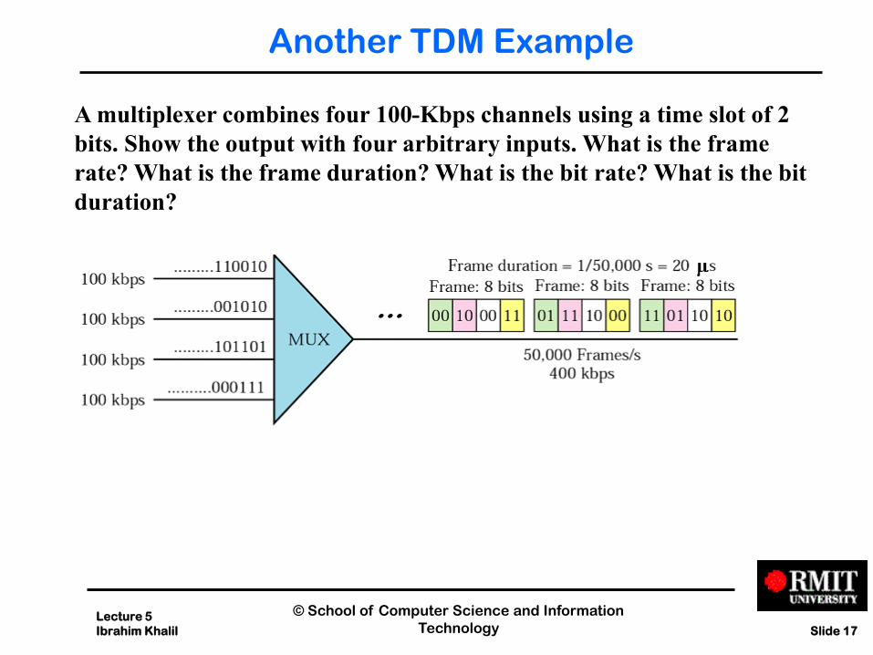
Another TDM Example
A multiplexer combines four 100-Kbps channels using a time slot of 2
bits. Show the output with four arbitrary inputs. What is the frame
rate? What is the frame duration? What is the bit rate? What is the bit
duration?
Lecture 5
Ibrahim Khalil
© School of Computer Science and Information
Technology Slide 17
Another TDM Example
A multiplexer combines four 100-Kbps channels using a time slot of 2
bits. Show the output with four arbitrary inputs. What is the frame
rate? What is the frame duration? What is the bit rate? What is the bit
duration?

Lecture 5
Ibrahim Khalil
© School of Computer Science and Information
Technology Slide 18
TDM Link Control
No headers and trailers
Data link control protocols not needed
Flow control
Data rate multiplexed line fixed
If one channel does not receive others
continue
Empty slots
Error control
Errors detected and handled by individual
channel systems

Lecture 5
Ibrahim Khalil
© School of Computer Science and Information
Technology Slide 19
Digital Carrier Systems
Hierarchy of TDM
USA/Canada/Japan use one system
ITU-T use a similar (but different) system
US system based on DS-1 format
Multiplexes 24 voice channels
Each frame has 8 bits per channel plus one framing bit
193 bits per frame

Lecture 5
Ibrahim Khalil
© School of Computer Science and Information
Technology Slide 20
DS and T lines rates
Service Line Rate
(Mbps) Voice Channels
DS-1 T-1 1.544 24
DS-2 T-2 6.312 96
DS-3 T-3 44.736 672
DS-4 T-4 274.176 4032
Lecture 5
Ibrahim Khalil
© School of Computer Science and Information
Technology Slide 21
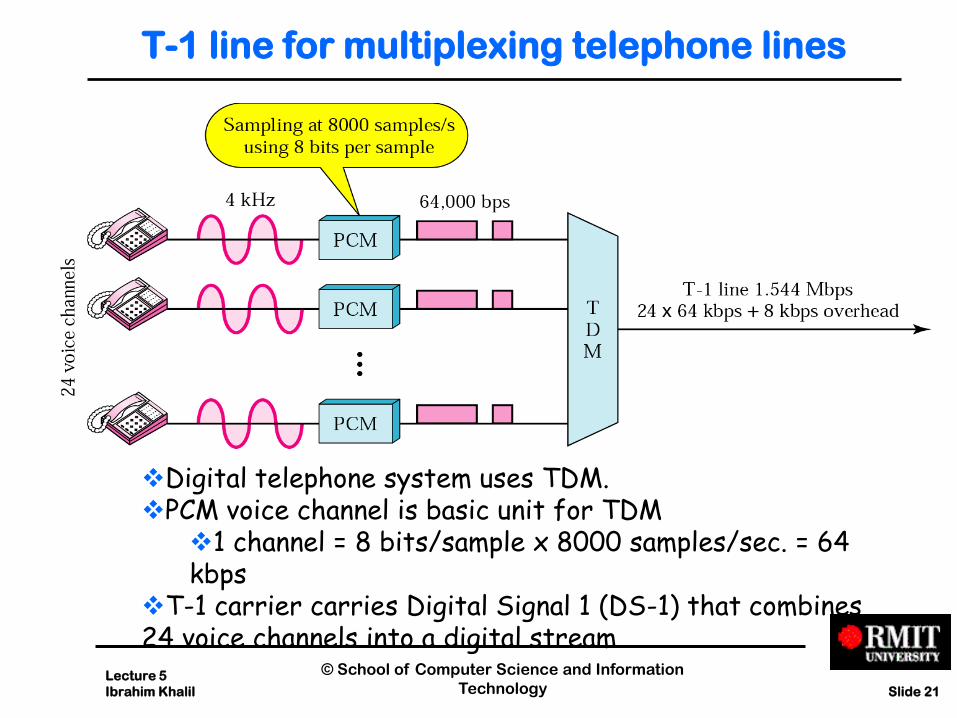
T-1 line for multiplexing telephone lines
Digital telephone system uses TDM. PCM voice channel is basic unit for TDM
1 channel = 8 bits/sample x 8000 samples/sec. = 64 kbps
T-1 carrier carries Digital Signal 1 (DS-1) that combines 24 voice channels into a digital stream

Lecture 5
Ibrahim Khalil
© School of Computer Science and Information
Technology Slide 22
T-1 frame structure
Bit Rate = 8000 frames/sec. x (1 + 8 x 24) bits/frame = 1.544 Mbps

Lecture 5
Ibrahim Khalil
© School of Computer Science and Information
Technology Slide 23
Statistical TDM
In Synchronous TDM many slots are wasted
Statistical TDM allocates time slots dynamically based on demand
Multiplexer scans input lines and collects data until frame full
Data rate on line lower than aggregate rates of input lines
Performance
Output data rate less than aggregate input rates
May cause problems during peak periods
Buffer inputs
Keep buffer size to minimum to reduce delay

Lecture 5
Ibrahim Khalil
© School of Computer Science and Information
Technology Slide 24
A1 A2
B1 B2
C2 C1
A2 B1 B2 C2 C1
(a)
(b) A1 Shared lines
Dedicated lines
Statistical Multiplexing:Tradeoff Delay for
Efficiency
Dedicated lines involve not waiting for other users, but lines are used inefficiently when user traffic is bursty
Shared lines concentrate packets into shared line; packets buffered (delayed) when line is not immediately available

Lecture 5
Ibrahim Khalil
© School of Computer Science and Information
Technology Slide 25
Summary
In this lecture, we have understood:
TDM, FDM, WDM, statistical multiplexing
Examples of TDM, FDM

Lecture 5
Ibrahim Khalil
© School of Computer Science and Information
Technology Slide 26
Next Time
We will know about
Flow control
Error control
Suggested Reading:
Chapters 7 (Stallings)