
An iron core probe based inter-laminar core fault detection technique for generator stator cores
Upload
nguyenthuyCategory
view
218download
5
RM CoreComponentsRM CoreComponents
RM CoresRM (Rectangular modulus) cores arose due to the demand for coil formers with integrated pins that allow forefficient winding and high PCB packing densities. Clamps engaging in recesses in the core base hold the cores inplace, meaning glue is not normally required in this process.All the cores adhere to specifications laid down in IEC 431 and in DIN 41980. The coil formers adhere to DIN41981.RM cores are designed for two main applications:
-Highly stable, extremely low loss filter inductors and other resonance determining inductors (F58, P11).-Low distortion broadband transmission at low signal modulation (F39, F10, F9).
RM cores can also be supplied without the centre hole. These have a higher AL value and cross sectional areaand are used for power transformer applications (F47, F44, F45, F5A).
RM Core
Coilformer
RM Core
Clip
Clip
Adjuster

RM 429-900-RM 429-900-
Part Number
64-020-66
64-021-66
76-024-95
Parameter Σl /A Effective Length Effective Area Minimum Area Effective Volume
Symbol C1 le Ae Amin Ve
Value 1.90mm-1 21.0mm 11.0mm² - 232.0mm³
Core Parameters
Electrical Specification
In accordance with IEC Document 60205.
Bobbins/Coil Formers Adjusters
Material AL Value Tolerance Gap Length Eff. Permeability Part Number
F9 1700 +30/-20% - 2570 29-900-36
F44 800 +30/-20% - 1210 29-900-44
P11 900 +30/-20% - 1360 29-900-41
P11 63 ±3% 0.18 95 29-901-41*
P11 100 ±3% 0.12 150 29-902-41*
P11 160 ±3% 0.06 240 29-903-41*
P11 250 ±3% 0.03 375 29-904-41*
P11 100 ±3% 0.12 150 29-912-41**
P11 160 ±3% 0.06 240 29-913-41**
P11 250 ±3% 0.03 375 29-914-41**
Mounting No. of Sections Pins Part Number
Vertical (AS) 1 4 60-901S64
Vertical (AS) 1 6 60-903S64
Other pin lengths or variation may be listed at the end of this section
AL Value
63/100
160/250
Clip
*Part number refers to a pair of cores fitted with a nut for adjust-able inductance assemblies.
**Part number denotes a gapped pair without nut.Other part numbers refer to half cores.
Core Dimensions (mm)
A
B
C
D
E
F
G
H
J
K
10.60 -11.00
10.30 -10.50
7.95 -8.35
3.70 -3.90
2.00 -2.10
7.00 -7.40
4.40 -4.60
9.50 -9.80
2.50 -2.70
8.76 -9.26
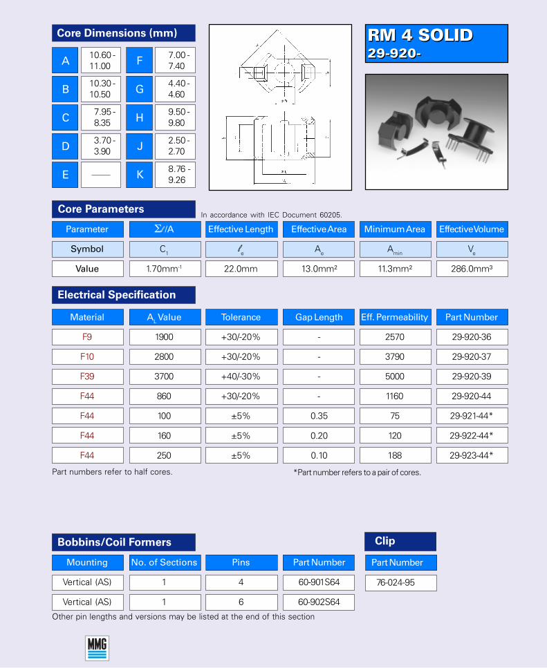
RM 4 SOLID29-920-RM 4 SOLID29-920-
76-024-95
Parameter Σl /A Effective Length Effective Area Minimum Area Effective Volume
Symbol C1 le Ae Amin Ve
Value 1.70mm-1 22.0mm 13.0mm² 11.3mm² 286.0mm³
Core ParametersIn accordance with IEC Document 60205.
Part numbers refer to half cores. *Part number refers to a pair of cores.
Other pin lengths and versions may be listed at the end of this section
Electrical Specification
Material AL Value Tolerance Gap Length Eff. Permeability Part Number
F9 1900 +30/-20% - 2570 29-920-36
F10 2800 +30/-20% - 3790 29-920-37
F39 3700 +40/-30% - 5000 29-920-39
F44 860 +30/-20% - 1160 29-920-44
F44 100 ±5% 0.35 75 29-921-44*
F44 160 ±5% 0.20 120 29-922-44*
F44 250 ±5% 0.10 188 29-923-44*
Bobbins/Coil Formers
Mounting No. of Sections Pins Part Number
Vertical (AS) 1 4 60-901S64
Vertical (AS) 1 6 60-902S64
Clip
Part Number
Core Dimensions (mm)
A
B
C
D
E
F
G
H
J
K
10.60 -11.00
10.30 -10.50
7.95 -8.35
3.70 -3.90
7.00 -7.40
4.40 -4.60
9.50 -9.80
2.50 -2.70
8.76 -9.26

RM 5-29-700-RM 5-29-700-
Parameter Σl /A Effective Length Effective Area Minimum Area Effective Volume
Symbol C1 le Ae Amin Ve
Value 1.00mm-1 20.80mm 20.80mm² 15.0mm² 430.0mm³
Core Parameters
Electrical Specification
In accordance with IEC Document 60205.
Bobbins/Coil Formers Adjusters
Material AL Value Tolerance Gap Length Eff. Permeability Part Number
F10 4800 +30/-20% - 3820 29-700-37
F39 6000 +40/-30% - 4775 29-700-39
P11 1840 +30/-20% - 1460 29-700-41
P11 100 ±3% 0.18 80 29-701-41*
P11 160 ±3% 0.12 128 29-702-41*
P11 250 ±3% 0.06 200 29-703-41*
P11 315 ±3% 0.03 250 29-704-41*
P11 100 ±5% 0.18 80 29-711-41**
P11 160 ±5% 0.12 128 29-712-41**
P11 250 ±5% 0.06 200 29-713-41**
Other pin lengths or variation may be listed at the end of this section
AL Value
100/160
250/315
Clip
*Part number refers to a pair of cores fitted with a nut for adjust-able inductance assemblies.
**Part number denotes a pair of cores without nut.Other part numbers refer to half cores.
Part Number
64-020-66
64-021-66
76-024-95
Mounting No. of Sections Pins Part Number
Vertical (AS) 1 4 60-701S64
Vertical (AS) 1 6 60-702S64
Core Dimensions (mm)
A
B
C
D
E
F
G
H
J
K
14.00 -14.60
10.30 -10.50
10.20 -10.60
4.70 -4.90
2.00 -2.10
6.30 -6.70
6.40 -6.80
11.80 -12.30
2.50 -2.70
8.76 -9.26

RM 5 SOLID29-720-RM 5 SOLID29-720-
76-024-95
Mounting No. of Sections Pins Part Number
Vertical (AS) 1 4 60-701S64
Vertical (AS) 1 6 60-702S64
Parameter Σl /A Effective Length Effective Area Minimum Area Effective Volume
Symbol C1 le Ae Amin Ve
Value 0.93mm-1 22.10mm 23.80mm² 18.0mm² 526.0mm³
Core ParametersIn accordance with IEC Document 60205.
Part numbers refer to half cores. *Part number refers to a pair of cores.
Other pin lengths and versions may be listed at the end of this section
Electrical Specification
Material AL Value Tolerance Gap Length Eff. Permeability Part Number
F9 3840 +30/-20% - 2840 29-720-36
F10 4815 +30/-20% - 3563 29-720-37
F39 6700 +40/-30% - 4960 29-720-39
F47 1520 +30/-20% - 1125 29-720-47
F44 1570 +30/-20% - 1160 29-720-44
F44 100 ±5% 0.35 74 29-721-44*
F44 160 ±5% 0.20 118 29-722-44*
F44 250 ±5% 0.12 185 29-723-44*
Bobbins/Coil Formers Clip
Part Number
Core Dimensions (mm)
A
B
C
D
E
F
G
H
J
K
14.00 -14.60
10.30 -10.50
10.20 -10.60
4.70 -4.90
6.30 -6.70
6.40 -6.80
11.80 -12.30
2.50 -2.70
8.76 -9.26
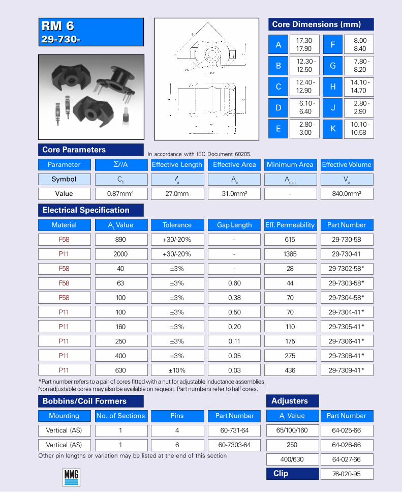
RM 629-730-RM 629-730-
*Part number refers to a pair of cores fitted with a nut for adjustable inductance assemblies.Non adjustable cores may also be available on request. Part numbers refer to half cores.
Parameter Σl /A Effective Length Effective Area Minimum Area Effective Volume
Symbol C1 le Ae Amin Ve
Value 0.87mm-1 27.0mm 31.0mm² - 840.0mm³
Core Parameters
Electrical Specification
In accordance with IEC Document 60205.
Bobbins/Coil Formers Adjusters
Material AL Value Tolerance Gap Length Eff. Permeability Part Number
F58 890 +30/-20% - 615 29-730-58
P11 2000 +30/-20% - 1385 29-730-41
F58 40 ±3% - 28 29-7302-58*
F58 63 ±3% 0.60 44 29-7303-58*
F58 100 ±3% 0.38 70 29-7304-58*
Other pin lengths or variation may be listed at the end of this section
Clip
Mounting No. of Sections Pins Part Number
Vertical (AS) 1 4 60-731-64
Vertical (AS) 1 6 60-7303-64
AL Value
65/100/160
250
400/630
Part Number
64-025-66
64-026-66
64-027-66
76-020-95
P11 100 ±3% 0.50 70 29-7304-41*
P11 160 ±3% 0.20 110 29-7305-41*
P11 250 ±3% 0.11 175 29-7306-41*
P11 400 ±3% 0.05 275 29-7308-41*
P11 630 ±10% 0.03 436 29-7309-41*
Core Dimensions (mm)
A
B
C
D
E
F
G
H
J
K
17.30 -17.90
12.30 -12.50
12.40 -12.90
6.10 -6.40
2.80 -3.00
8.00 -8.40
7.80 -8.20
14.10 -14.70
2.80 -2.90
10.10 -10.58
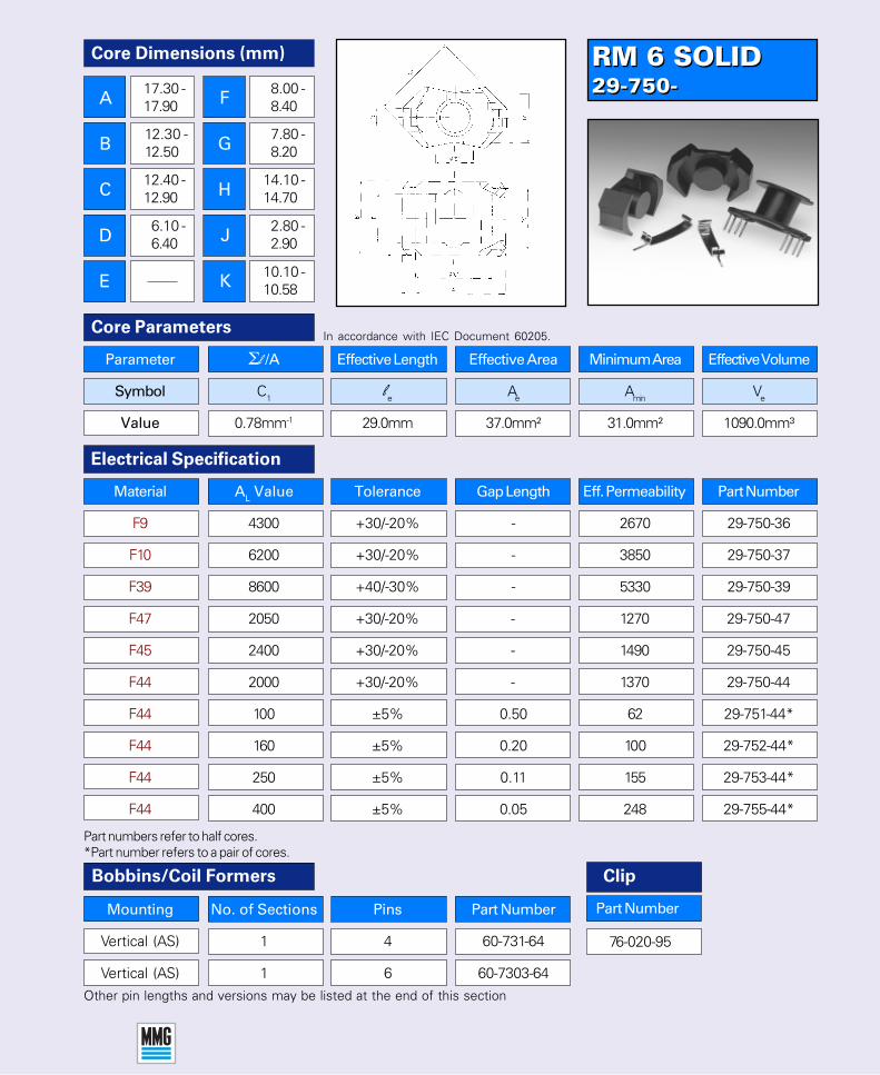
RM 6 SOLID29-750-RM 6 SOLID29-750-
76-020-95
Mounting No. of Sections Pins Part Number
Vertical (AS) 1 4 60-731-64
Vertical (AS) 1 6 60-7303-64
Parameter Σl /A Effective Length Effective Area Minimum Area Effective Volume
Symbol C1 le Ae Amin Ve
Value 0.78mm-1 29.0mm 37.0mm² 31.0mm² 1090.0mm³
Core ParametersIn accordance with IEC Document 60205.
Other pin lengths and versions may be listed at the end of this section
Electrical Specification
Bobbins/Coil Formers
F44 2000 +30/-20% - 1370 29-750-44
F44 100 ±5% 0.50 62 29-751-44*
F44 160 ±5% 0.20 100 29-752-44*
F44 250 ±5% 0.11 155 29-753-44*
F44 400 ±5% 0.05 248 29-755-44*
Material AL Value Tolerance Gap Length Eff. Permeability Part Number
F9 4300 +30/-20% - 2670 29-750-36
F10 6200 +30/-20% - 3850 29-750-37
F39 8600 +40/-30% - 5330 29-750-39
F47 2050 +30/-20% - 1270 29-750-47
F45 2400 +30/-20% - 1490 29-750-45
Part numbers refer to half cores.*Part number refers to a pair of cores.
Clip
Part Number
Core Dimensions (mm)
A
B
C
D
E
F
G
H
J
K
17.30 -17.90
12.30 -12.50
12.40 -12.90
6.10 -6.40
8.00 -8.40
7.80 -8.20
14.10 -14.70
2.80 -2.90
10.10 -10.58

RM 729-7600-RM 729-7600-
Part numbers refer to half cores.**Part number denotes solid core.
Parameter Σl /A Effective Length Effective Area Minimum Area Effective Volume
Symbol C1 le Ae Amin Ve
Value 0.74mm-1 29.80mm 40.00mm² - 1200.00mm³
Core Parameters
Electrical Specification
In accordance with IEC Document 60205.
Bobbins/Coil Formers Adjusters
Other pin lengths or variation may be listed at the end of this section
Clip
Mounting No. of Sections Pins Part Number
Vertical (AS) 1 4 60-7601-64
Vertical (AS) 1 6 60-7604-64
AL Value
63/100/160
250
400/630
Part Number
64-025-66
64-026-66
64-027-66
76-021-95
Material AL Value Tolerance Gap Length Eff. Permeability Part Number
F9 4690 +30/-20% - 29-7600-36
P11 2860 +30/-20% - 29-7600-41
P11 100 ±3% 0.76 29-7604-41*
P11 160 ±3% 0.40 29-7605-41*
P11 250 ±3% 0.25 29-7606-41*
P11 400 ±3% 0.15 29-7608-41*
P11 100 ±5% 0.70 29-7704-41**
P11 160 ±5% 0.40 29-7705-41**
P11 250 ±5% 0.25 29-7706-41**
P11 400 ±5% 0.15 29-7708-41***Part number refers to a pair of cores fitted with a nut for adjust-able inductance assemblies.
Core Dimensions (mm)
A
B
C
D
E
F
G
H
J
K
19.50 -20.30
13.30 -13.50
14.76 -15.36
6.96 -7.24
2.94 -3.12
8.50 -8.90
16.50 -17.20
3.20 -3.60
11.06 -11.54

RM 7 SOLID29-7800-RM 7 SOLID29-7800-
Mounting No. of Sections Pins Part Number
Vertical (AS) 1 4 60-7601-64
Vertical (AS) 1 8 60-7604-64
Parameter Σl /A Effective Length Effective Area Minimum Area Effective Volume
Symbol C1 le Ae Amin Ve
Value 0.70mm-1 30.40mm 43.0mm² 39.0mm² 1340.0mm³
Core ParametersIn accordance with IEC Document 60205.
Other pin lengths and versions may be listed at the end of this section
Electrical Specification
Bobbins/Coil Formers
Part numbers refer to half cores.*Part number refers to a pair of cores.
F44 100 ±5% 0.70 55 29-7804-44*
F44 160 ±5% 0.40 90 29-7805-44*
F44 250 ±5% 0.25 140 29-7806-44*
F44 400 ±5% 0.15 225 29-7808-44*
Material AL Value Tolerance Gap Length Eff. Permeability Part Number
F9 5000 +30/-20% - 3150 29-7800-36
F10 7000 +30/-20% - 3900 29-7800-37
F39 10000 +40/-30% - 5700 29-7800-39
F44 2370 +30/-20% - 1320 29-7800-44
F5A 2850 +30/-20% - 1590 29-7800-49
76-021-95
Clip
Part Number
Core Dimensions (mm)
A
B
C
D
E
F
G
H
J
K
19.50 -20.30
13.30 -13.50
14.76 -15.36
6.96 -7.24
8.50 -8.90
16.50 -17.20
3.20 -3.60
11.06 -11.54

RM 829-790-RM 829-790-
Part numbers refer to half cores.Non adjustable type may be available on request.
Parameter Σl /A Effective Length Effective Area Minimum Area Effective Volume
Symbol C1 le Ae Amin Ve
Value 0.68mm-1 35.50mm 52.00mm² - 1850.00mm³
Core Parameters
Electrical Specification
In accordance with IEC Document 60205.
Bobbins/Coil Formers Adjusters
Other pin lengths or variation may be listed at the end of this section
Clip
Mounting No. of Sections Pins Part Number
Vertical (Z) 1 8 60-792-64
Vertical (AS) 1 12 60-793-64
AL Value
63/100/160
250/400
630
Part Number
64-4834-66
64-4833-66
64-4835-66
76-022-95
Material AL Value Tolerance Gap Length Eff. Permeability Part Number
P11 2500 +30/-20% - 1350 29-790-41
F58 1170 +30/-20% - 630 29-790-58
F58 63 ±3% 1.40 34 29-7903-58*
F58 100 ±3% 0.80 54 29-7904-58*
P11 100 ±3% 0.86 54 29-7904-41*
P11 160 ±3% 0.40 86 29-7905-41*
P11 250 ±3% 0.23 135 29-7906-41*
P11 315 ±3% 0.18 170 29-7907-41*
P11 400 ±3% 0.13 216 29-7908-41*
P11 630 ±3% 0.08 341 29-7909-41**Part number refers to a pair of cores fitted with a nut foradjustable inductance assemblies.
Core Dimensions (mm)
A
B
C
D
E
22.30 -23.20
16.30 -16.50
17.00 -17.70
8.25 -8.55
4.40 -4.60
10.80 -11.20
10.50 -11.40
18.90 -19.70
4.30 -5.10
14.06 -14.54
F
G
H
J
K

RM 8 SOLID29-810-RM 8 SOLID29-810-
Mounting No. of Sections Pins Part Number
Vertical (Z) 1 8 60-792-64
Vertical (AS) 1 12 60-793-64
Parameter Σl /A Effective Length Effective Area Minimum Area Effective Volume
Symbol C1 le Ae Amin Ve
Value 0.59mm-1 38.0mm 64.0mm² 55.0mm² 2430.0mm³
Core ParametersIn accordance with IEC Document 60205.
Other pin lengths and versions may be listed at the end of this section
Electrical Specification
Bobbins/Coil Formers
Part numbers refer to half cores.
F5A 4000 +30/-20% - 1880 29-810-49
F44 100 ±5% 0.70 47 29-811-44*
F44 160 ±5% 0.40 75 29-812-44*
F44 250 ±5% 0.25 117 29-813-44*
F44 315 ±5% 0.15 188 29-814-44*
Material AL Value Tolerance Gap Length Eff. Permeability Part Number
F9 5700 +30/-20% - 2675 29-810-36
F10 8375 +30/-20% - 3930 29-810-37
F39 12500 +40/-30% - 5870 29-810-39
F44 2905 +30/-20% - 1365 29-810-44
F45 3300 +30/-20% - 1550 29-810-45
76-022-95
Clip
Part Number
Core Dimensions (mm)
A
B
C
D
E
22.30 -23.20
16.30 -16.50
17.00 -17.70
8.25 -8.55
F
G
H
J
K
10.80 -11.20
10.50 -11.00
18.90 -19.70
4.30 -5.10
14.06 -14.54
*Part number refers to a pair of cores.

RM 1029-830-RM 1029-830-
Part numbers refer to half cores.Non adjustable type may be available on request.
Parameter Σl /A Effective Length Effective Area Minimum Area Effective Volume
Symbol C1 le Ae Amin Ve
Value 0.50mm-1 42.00mm 83.00mm² - 3470.00mm³
Core Parameters
Electrical Specification
In accordance with IEC Document 60205.
Bobbins/Coil Formers Adjusters
Other pin lengths or variation may be listed at the end of this section
Clip
Style No. of Sections Pins Part Number
Vertical (Z) 1 8 60-822-64
Vertical (AS) 1 12 60-823-64
AL Value
63/100/160/250
400/630
1000
Part Number
64-8104-66
64-4843-66
64-4845-66
76-023-95
Material AL Value Tolerance Gap Length Eff. Permeability Part Number
P11 3960 +30/-20% - 1575 29-830-41
F58 1600 +30/-20% - 635 29-830-58
F58 63 ±3% 2.60 25 29-8303-58*
F58 100 ±3% 1.50 40 29-8304-58*
P11 160 ±3% 0.90 64 29-8305-41*
P11 250 ±3% 0.55 99 29-8306-41*
P11 400 ±3% 0.21 159 29-8308-41*
P11 630 ±3% 0.13 250 29-8309-41*
P11 1000 ±3% 0.08 398 29-8310-41*
*Part number refers to a pair of cores fitted with a nut for adjust-able inductance assemblies.
Core Dimensions (mm)
A
B
C
D
E
27.20 -28.40
18.50 -18.70
21.20 -22.10
10.50 -10.90
5.40 -5.60
12.40 -13.00
13.00 -13.50
23.60 -24.70
5.00 -5.20
15.96 -16.94
F
G
H
J
K
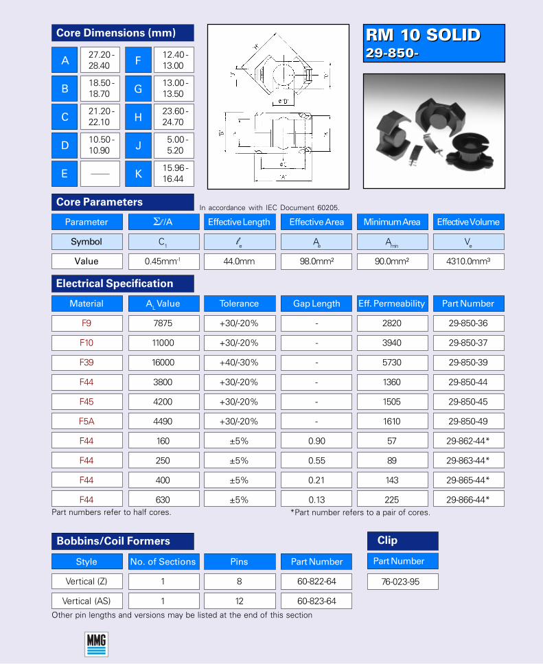
RM 10 SOLID29-850-RM 10 SOLID29-850-
Style No. of Sections Pins Part Number
Vertical (Z) 1 8 60-822-64
Vertical (AS) 1 12 60-823-64
Parameter Σl /A Effective Length Effective Area Minimum Area Effective Volume
Symbol C1 le Ae Amin Ve
Value 0.45mm-1 44.0mm 98.0mm² 90.0mm² 4310.0mm³
Core ParametersIn accordance with IEC Document 60205.
Other pin lengths and versions may be listed at the end of this section
Electrical Specification
Bobbins/Coil Formers
Part numbers refer to half cores.
F5A 4490 +30/-20% - 1610 29-850-49
F44 160 ±5% 0.90 57 29-862-44*
F44 250 ±5% 0.55 89 29-863-44*
F44 400 ±5% 0.21 143 29-865-44*
F44 630 ±5% 0.13 225 29-866-44*
Material AL Value Tolerance Gap Length Eff. Permeability Part Number
F9 7875 +30/-20% - 2820 29-850-36
F10 11000 +30/-20% - 3940 29-850-37
F39 16000 +40/-30% - 5730 29-850-39
F44 3800 +30/-20% - 1360 29-850-44
F45 4200 +30/-20% - 1505 29-850-45
76-023-95
Clip
Part Number
Core Dimensions (mm)
A
B
C
D
E
27.20 -28.40
18.50 -18.70
21.20 -22.10
10.50 -10.90
12.40 -13.00
13.00 -13.50
23.60 -24.70
5.00 -5.20
15.96 -16.44
F
G
H
J
K
*Part number refers to a pair of cores.

RM 12i SOLID29-940-RM 12i SOLID29-940-
76-085-95
Parameter Σl /A Effective Length Effective Area Minimum Area Effective Volume
Symbol C1 le Ae Amin Ve
Value 0.388mm-1 56.60mm 146.00mm² 125mm2 8340.00mm³
Core Parameters
Electrical Specification
In accordance with IEC Document 60205.
Bobbins/Coil Formers
Other pin lengths or variation may be listed at the end of this section
Style No. of Sections Pins Part Number
Vertical (AS) 1 12 60-930-64
Vertical (DIL) 1 12 60-940-76
Material AL Value Tolerance Gap Length Eff. Permeability Part Number
F47 4750 +30/-20% - 1465 29-940-47
F44 5000 +30/-20% - 1545 29-940-44
F5A 5800 +30/-20% - 1790 29-940-49
F5A 160 ±5% 1.50 49 29-941-49*
F5A 250 ±5% 0.90 77 29-942-49*
F5A 400 ±5% 0.50 123 29-943-49*
Core Dimensions (mm)
A
B
C
D
E
36.10 -37.40
24.30 -24.60
25.00 -26.00
12.40 -12.80
16.80 -17.70
15.60 -16.10
27.70 -28.80
4.90 -5.10
21.40 -21.98
Part numbers refer to half cores. *Part number refers to a pair of cores.
NOTE: This core range now complies with the new industrial requirements for powerhandling and should be ordered as replacements for previous RM12 cores supplied underPart no’s. 29-930-xx to 29-939-xx.The clips 76-030-95 are also not compatible with this new range.
Clip
Part Number
F
G
H
J
K
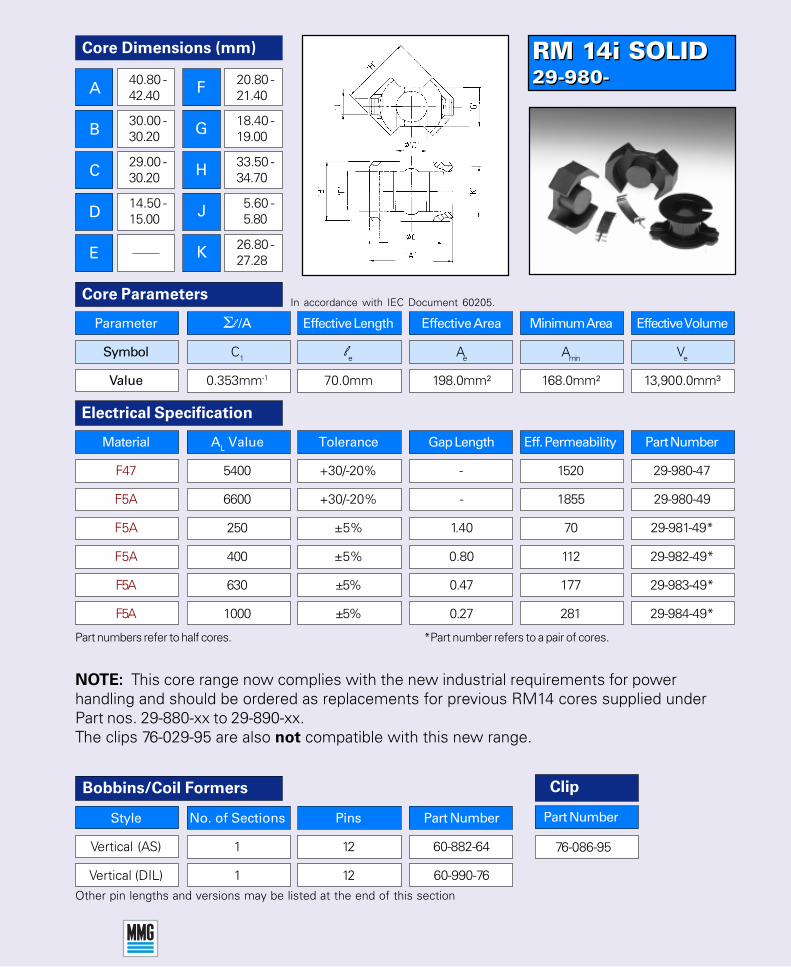
RM 14i SOLID29-980-RM 14i SOLID29-980-
Style No. of Sections Pins Part Number
Vertical (AS) 1 12 60-882-64
Vertical (DIL) 1 12 60-990-76
Parameter Σl /A Effective Length Effective Area Minimum Area Effective Volume
Symbol C1 le Ae Amin Ve
Value 0.353mm-1 70.0mm 198.0mm² 168.0mm² 13,900.0mm³
Core ParametersIn accordance with IEC Document 60205.
Other pin lengths and versions may be listed at the end of this section
Electrical Specification
Bobbins/Coil Formers
Part numbers refer to half cores.
F5A 1000 ±5% 0.27 281 29-984-49*
Material AL Value Tolerance Gap Length Eff. Permeability Part Number
F47 5400 +30/-20% - 1520 29-980-47
F5A 6600 +30/-20% - 1855 29-980-49
F5A 250 ±5% 1.40 70 29-981-49*
F5A 400 ±5% 0.80 112 29-982-49*
F5A 630 ±5% 0.47 177 29-983-49*
76-086-95
Clip
Part Number
*Part number refers to a pair of cores.
Core Dimensions (mm)
A
B
C
D
E
40.80 -42.40
30.00 -30.20
29.00 -30.20
14.50 -15.00
20.80 -21.40
18.40 -19.00
33.50 -34.70
5.60 -5.80
26.80 -27.28
NOTE: This core range now complies with the new industrial requirements for powerhandling and should be ordered as replacements for previous RM14 cores supplied underPart nos. 29-880-xx to 29-890-xx.The clips 76-029-95 are also not compatible with this new range.
F
G
H
J
K


