RLC-DS-2 June1999 Series R Rotary Liquid Chiller 70 to 400 ...
68
RLC-DS-2 June1999 Series R ® Rotary Liquid Chiller 70 to 400 Tons Air-Cooled RLC-DS-2 Built For the Industrial and Commercial Markets
Transcript of RLC-DS-2 June1999 Series R Rotary Liquid Chiller 70 to 400 ...

1
RLC-DS-2June1999
Series R®
Rotary Liquid Chiller
70 to 400 TonsAir-Cooled
RLC
-DS
-2
Built For the Industrial and Commercial Markets

2©American Standard Inc. 1999
FeaturesandBenefits
The Series R® Helical RotaryCompressor
• Direct-drive, low speed for highefficiency and high reliability.
• Simple design with only three movingparts, resulting in high reliability andlow maintenance.
• Field serviceable compressor for easymaintenance.
• Precise rotor tip clearance for optimalefficiency.
• Suction gas-cooled motor. The motoroperates at lower temperatures forlonger motor life.
• Five minute start-to-start/two minutestop-to-start antirecycle timer allows forcloser water loop temperature control.
DesignedTo Perform,Built To LastThe Series R® helical rotary chiller is anindustrial grade design built for thecommercial market. It is ideal for officebuildings, hospitals, schools, retailersand industrials.
• Years of research and testing. TheTrane helical rotary compressor hasamassed thousands of hours of testing,much of it at severe operatingconditions beyond normal airconditioning applications.
• Proven track record. The TraneCompany is the world’s largestmanufacturer of large helical rotarycompressors. Over 60,000 commercialand industrial installations worldwidehave proven that the Trane helicalrotary compressor has a reliability rateof greater than 99.5 percent in the firstyear of operation – unequalled in theindustry.
Applications
• Comfort cooling.• Industrial process cooling.• Ice/thermal storage.• Heat recovery.• Low temperature process cooling.
Trane air-cooled 200-ton chiller.

3
Contents
Optimum Efficiencies
• Unsurpassed full load efficiency (EER)
• Great part-load efficiency due to anelectronic expansion valve and TraneHelirotor® compressors.
• PID chilled water setpoint controlmaintains chilled water supply within± 1/2 F of setpoint.
Trouble-Free Installation, Start-Up andOperation
• Small operating footprint insures easyretrofit capabilities.
• Factory testing insures trouble-freestart-up.
• Factory-installed, fully-tested controlsand options keep start-up time andexpenses minimized.
• Adaptive Control™ Microprocessor— optimizes efficiencies— prevents nuisance trip-outs— prevents unnecessary service calls
and unhappy tenants
• Superior microprocessor control— over 90 diagnostic and operating
conditions— display chiller temperatures and
pressures— Trane Integrated Comfort™ system
(ICS) interface.
The standard ARI rating condition(54/44 F and 95 F) and IPLV are ARIcertified. All other ratings, including thefollowing, are outside the scope of thecertification program and are excluded:
• Glycol.• 50 Hz.• Unit sizes RTAA 240-400.• Remote evaporator models. Water Chiller Systems Business Unit
Features and Benefits 2
Model Number Description 12
General Data 13
Selection Procedure 15
Application Considerations 16
Performance Adjustment Factors 20
Performance Data 26
Electrical Data 37
Jobsite Connections 39
Controls 46
Dimensional Data 53
Weights 56
Options 57
Typical Wiring Diagrams 58
Features Summary 64
Mechanical Specifications 65

4
FeaturesandBenefits
Fewer Moving PartsThe “intermediate” helical rotary screwcompressor has only three movingparts: the two rotor assemblies and thecapacity controlling slide valve. The“general purpose” helical rotary screwcompressor has only four moving parts:two rotor assemblies, the variableunloader valve, and the step unloadervalve. Unlike reciprocatingcompressors, the Trane helical rotaryscrew compressor has no pistons,connecting rods, suction and discharge
valves or mechanical oil pump. In fact,a typical reciprocating compressor has15 times as many critical parts as theSeries R compressor. Fewer movingparts lead to increased reliability andlonger life.
Cutaway of a 100-ton intermediatecompressor.
Trane helical rotary screw compressorcomponent parts versus reciprocatingcompressor components.
UnequaledReliabilityProven Reliable DesignThe air-cooled Series R® chiller utilizestwo, three, or four Trane helical rotaryscrew compressors that operate on tworefrigeration circuits. The tonnages ofthese compressors is 35, 40, 50, 60, 70,85, and 100 ton, and they are groupedtogether in different configurations tomake up the air-cooled product linefrom 70 to 400 tons.
Trane air-cooled helical rotary screwcompressors were designed, tested andbuilt to the same rugged standards asthe CenTraVac® chiller compressors.Since the introduction of Trane’s helicalrotary screw compressors to air-cooledapplications, their reliability has beenoutstanding. This is proven by the factthat over 60,000 Trane helical rotarycompressors are operating worldwideand have maintained a reliability rate ofgreater than 99.5 percent in the firstyear of operation. The Trane helicalrotary screw compressor design andreliability is outstanding whencompared to a typical reciprocatingcompressor design which historicallyhas had a failure rate of two to fourpercent in the first year alone.
Air-cooled Series R chillers from130-400 tons utilize the “intermediate”compressor. These compressorsunload from fully loaded to theminimum capacity of the compressorutilizing a single unloading method, theslide valve. This slide valve ispositioned over both the male andfemale rotors. With the addition of the70, 80, 90, 110, and 125 ton chillers toour air-cooled product line, we havealso added a new design concept to theHelirotor compressor and call it the“general purpose” compressor. Thecapacity control of this new design isachieved in much the same manner asthe larger compressors by modulationof a loader, unloader mechanism drivenby oil pressure actuated pistons. Asimple piston is used to load andunload the step unloader valve at start-up allowing the compressor to start inan unloaded state for increasedreliability. As the load increases ordecreases the compressor uses avariable unloader valve to modulatecapacity and closely match the requiredcooling load.

5
FeaturesandBenefits
Resistance To Liquid SluggingThe robust design of the Series Rcompressor can ingest amounts ofliquid refrigerant that would severelydamage reciprocating compressorvalves, piston rods and cylinders.
Proven Design Through Testing andResearch Test To FailureIt takes a little getting use to, but weMUST fail a lot of compressors in thelaboratory so they don’t fail in the field.Without failures, there is no way to becertain whether the final design isconservative or potentially unreliable.
End view showing male and female rotors and slide valve onan 85-ton intermediate compressor.
The Compressor Accelerated Life Testis proven to induce failure. This test isdesigned to overstess all parts andquickly identify any weak elements.The test conditions are far moreextreme than actual field applications.Engineers fail, redesign, fail, redesign,etc., until finally, reliability in the field isassured. Our leadership in helicalcompressor technology is recognizedworldwide. It is the basis for thesuccessful introduction of the reliableTrane helical rotary screw compressor— right from the start!

6
FeaturesandBenefits
OptimumEfficienciesUnsurpassed Full LoadEfficiency
Precise Rotor Tip ClearancesHigher energy efficiency in a helicalrotary compressor is obtained byreducing the rotor tip clearances.This reduces the leakage betweenhigh and low pressure cavitiesduring compression. Precise rotor tipclearance is achieved with the latestmanufacturing and machiningtechnology. Trane is the first helicalrotary compressor manufacturer toelectronically check compressor partsmachining accuracy as part of thestandard production process.
Optimized Compressor Parts ProfilesRotor and slide valves are uniquedesigns, optimized for the airconditioning application. The rotors aredesigned for the pressure ranges in theair conditioning application. Theunloader valve has a unique profile thatresulted from computer performancemodeling in typical part-load situations.
Advanced Heat Transfer SurfacesCondenser and evaporator tubes usethe latest heat transfer technology forincreased efficiency.
Great Part Load EfficiencyWith Trane Helical RotaryScrew Compressors andElectronic Expansion Valve
Trane Helical Rotary ScrewCompressor Means Superior Part LoadPerformanceThe air-cooled Series R® chiller hasgreat part-load performance. The slidevalve on the “intermediatecompressors” has a Trane designedprofile that resulted from computerperformance modeling in typical part-load situations. The combinationpatented unloading system on the“general purpose” compressor utilizesthe variable unloading valve for themajority of the unloading functionsimilar to that of the slide valve. The“general purpose” compressor alsouses a step unloader valve which is asingle unloading step to achieve theminimum unloading point of thecompressor. The result of both of thesedesigns is optimized part-loadperformance far superior to singlereciprocating compressors.

7
FeaturesandBenefits
Electronic Expansion ValveWhen coupled with Trane’s AdaptiveControl™ microprocessor, our electronicexpansion valve significantly improvespart-load performance of the Series Rchiller by minimizing superheat in theevaporator and allowing the chiller torun at reduced condensingtemperatures. Chillers which useconventional TXV’s must run at higherhead pressures and consume more
power than necessary at part-loads.Additionally, the electronic expansionvalve and its controls allow muchbetter stability and control overdynamic load and head changes.Under these conditions a conventionalTXV may never achieve control stabilityand extended periods of TXV“hunting” and liquid slugging arecommon.
Capacity Control and Load MatchingInfinitely variable compressormodulation allows the compressorcapacity to exactly match the buildingcooling load. Reciprocating chillers thatrely on stepped capacity control mustrun at a capacity equal to or greaterthan the load. Much of this excesscapacity is lost because overcoolinggoes toward building latent heatremoval, causing the building to bedried beyond normal comfortrequirements. The result is an increasein chiller energy costs, particularly atthe part-load conditions at which thechiller operates most of the time.
PID Chilled Water SetpointControl Through Slide ValveModulation
Maintain Chilled Water Supply Within± 1/2 F of SetpointReciprocating chillers that have stepcapacity control typically can onlymaintain water temperature to around± 2 F. With the air-cooled Series Rchiller, maintaining temperature controlhas never been so accurate.
Reduce Compressor CyclingModulating capacity control offersbetter compressor reliability.Compressor cycling, typical ofreciprocating compressors, willdecrease compressor component life.Parts like motors and valves do notstand up well to excessive compressorcycling.
Cutaway view of Trane’s electronic expansion valve.

8
FeaturesandBenefits
Adaptive Control™ MicroprocessorThe air-cooled Series R® chilleremploys the most advancedmicroprocessor control available onany packaged water chiller in themarketplace and features the AdaptiveControl microprocessor. So what is theAdaptive Control microprocessor?Adaptive Control means the UnitControl Module (UCM) directly sensesthe control variables that governoperation of the chiller: motor currentdraw, evaporator temperature,condenser temperature, etc.
When any of the variables approachesa limit condition where the unit may bedamaged or shut down on a safety,the UCM takes corrective action toavoid shutdown and keep the chilleroperating. It does this throughcombined actions of compressor slidevalve modulation, electronic expansionvalve modulation and fan staging.Additionally, the UCM optimizes totalunit power consumption duringnormal operating conditions. No otherchiller control system in themarketplace duplicates thisperformance.
Unit control module for 130 to 400- ton air-cooled chillers.
Clear Language Display Keypad (UCM)— Air-Cooled, 70 to 125 tons.
Trouble-Free Installation,Start-Up and Operation
The End Of Nuisance Trip-Outs AndUnnecessary Service Calls?Unnecessary service calls and unhappytenants are avoided. The unit does notnuisance trip or unnecessarily shutdown. Only when the UCM hasexhausted the corrective actions it cantake and the unit is still violating anoperating limit will the unit shut down.CONTROLS ON OTHER CHILLERSTYPICALLY SHUT DOWN THECHILLER, QUITE PROBABLY JUSTWHEN IT IS NEEDED THE MOST.
For example:A typical five-year-old chiller with dirtycoils might trip-out on high pressurecutout on a 100 F day in August. A hotday is just when comfort cooling isneeded the most. In contrast, the air-cooled Series R chiller with an AdaptiveControl microprocessor will stage fanson, modulate electronic expansionvalve, and modulate slide valve as itapproaches a high pressure cutout.Thereby KEEPING THE CHILLERON-LINE JUST WHEN YOU NEED ITTHE MOST.

9
FeaturesandBenefits
Close Spacing Of ChillerThe air-cooled Series R® chiller has thetightest recommended side clearancein the industry, four feet, but that is notall. In situations where equipment mustbe installed with less clearance thanrecommended, such as frequentlyoccurs in retrofit and rooftopapplications, restricted air flow iscommon. Conventional chillers maynot work at all. However, the air-cooledSeries R chiller with Adaptive Control™microprocessor will simply make asmuch chilled water as it can given theactual installed conditions, stay on lineduring any unforeseen abnormalconditions, and optimize itsperformance. Consult your Trane salesengineer for more details.
Lower Service ExpenseNuisance service calls are avoided.When there is a real problem that mustbe corrected, the UCM’s extensivediagnostics help assure that theproblem is quickly identified. Downtime and service expense areminimized. And with the ability tocommunicate with the Trane IntegratedComfort™ system or a remote displaypanel, service problems can beidentified and diagnosed remote to theinstallation.
Factory Testing Means Trouble-FreeStart-UpAll air-cooled Series R chillers aregiven a complete functional test atthe factory. This computer-basedtest program completely checksthe sensors, wiring, electricalcomponents, microprocessor function,communication capability, expansionvalve performance and fans. Inaddition, each compressor is run testedwith refrigerant to verify capacity andpower consumption. Where applicable,each unit is factory preset to thecustomer’s design conditions, includingleaving water temperature setpoint,current limit, and reset temperaturesetpoint. The end result of this testprogram is that the chiller arrives atthe jobsite fully tested and ready to goto work.
Factory Installed And Tested Controls/Options Speed InstallationAll Series R chiller options, includingcontrol power transformer, starterdisconnect, low ambient control,ambient temperature sensor, lowambient lockout, communicationinterface and ice making controls arefactory installed and tested. Somemanufacturers send options in piecesto be field installed. With Trane, thecustomer saves on installation expenseand has assurance that ALL chillercontrols/options have been tested andwill function as expected.

10
FeaturesandBenefits
Superior ControlUnit Control ModuleTrane’s new Adaptive Control™microprocessor control systemenhances the air-cooled Series R chillerby providing the very latest chillercontrol technology.
The Trane air-cooled Series R chillersranging from 130 to 400 ton sizes offeran easy-to-use operator interface panelthat displays all operating and safetycodes with over 60 diagnosticsincluded. Adaptive Controlmicroprocessor features shut down thechiller only if absolutely necessary. Theunit control module (UCM) anticipatespotential problems and initiatescorrective actions to prevent nuisancetripouts.
State-of-the-Art EquipmentThe new 70 to 125 air-cooled chillersoffer the exclusive Trane AdaptiveControl logic with the Clear LanguageDisplay (UCM). The Clear LanguageDisplay has various functions thatallow the operator to read unitinformation and adjust setpoints. TheClear Language Display panel has 16keys, the readout screen is a two-line,40 character liquid crystal with abacklight. The backlight allows theoperator to read the display in low-lightconditions.
Unit Control Module Features
Equal Compressor SequencingTrane maximizes both compressor andmotor life by equalizing both thenumber of starts and the operatinghours. The UCM will start thecompressor with the least number ofstarts and turn off the compressor withthe most operating hours.Conventional “auto” lead-lag controlwill equalize starts, but running hourswill typically be unequal. Equalizingboth starts and running hours willprovide equal compressor wear.
Internal “Built-In” Chiller FlowProtectionThe UCM automatically detects a nowaterflow condition. An external flowswitch is not required, which lowerscosts versus typical chillers. Built-inflow protection also eliminatesnuisance flow switch problems.
Remote Clear Language Display Panelfor 70 to 125-ton air-cooled chillers.
Remote Display Panel — Air-Cooled,130 to 400 tons.

11
FeaturesandBenefits
Easy Chiller System LoggingThe UCM displays data required to logthe chiller system. The followinginformation is available either asstandard or as an option with the Air-Cooled Series R Chiller microprocessor:
• Entering and leaving chilled watertemperatures
• Ambient air temperature• Evaporator and condenser refrigerant
temperatures and pressures• Compressor suction temperature• Percent RLA for each compressor• Percent line voltage• Compressor starts and running hours• Active setpoints:
chilled water setpointcurrent limit setpointice termination setpointlow ambient lockout setpoint
• Over 90 diagnostic and operatingconditions
• Part failure diagnostics:water temperature sensorsrefrigerant temperature sensorscompressor contactors
Remote Display PanelTrane air-cooled Series R® chillers areavailable with a twisted pair connectionto an optional remote display panel.Chiller operation can be controlledsimilarly to the control interface on thechiller itself. Through a twisted pair ofwires the unit can be turned on or off,change the chilled water setpoint, anddisplay over 90 operating anddiagnostic conditions. The remotedisplay panel can be mounted indoorsso access to chiller information is juststeps away, eliminating any need to gooutdoors or on the roof.
Remote display panels designed for air-cooled chillers of 130-400 ton rangescan control one unit. However thenewly designed clear language displayfor chiller sizes of 70-125 tons has theability to control multiple units. In amultiple unit configuration, the RemoteClear Language Display Panel has thecapability to communicate with up tofour units. Each unit requires a separatecommunication link with the RemoteDisplay Panel.
Easy Interface To The BuildingManagement SystemControlling the air-cooled Series Rchiller with building managementsystems is state-of-the-art yet simple.
Chiller inputs include:• Chiller enable/disable• Circuit enable/disable• Chilled water setpoint• Current limit setpoint• Ice making enable
Chiller outputs include:• Compressor running indication• Alarm indication (CKt 1/CKt2)• Maximum capacity
Trane Chiller Plant Manager/ICSThe Tracer® Chiller Plant ManagerBuilding Management Systemprovides building automation andenergy management functions throughstand- alone control. The Chiller PlantManager is capable of monitoring andcontrolling your entire chiller plantsystem.
Application software available:• Time-of-day scheduling• Duty cycle• Demand limiting• Chiller sequencing• Process control language• Boolean processing• Zone control• Reports and logs• Custom messages• Run time and maintenance• Trend log• Totalizing• PID control loops
And of course, Trane’s Chiller PlantManager Panel can be used on a stand-alone basis or tied into a completebuilding automation system.
Chiller plant screen from Trane’s Tracer® Chiller Plant Manager.

12
ModelNumberDescription
Model NomenclatureDigit Number
1 2 3 4 5 6 7 8 9 10 11 12 13 14 15 16 17
70-125 Tons
Digits 1, 2 — Unit ModelRT = Rotary Chiller
Digit 3 — Unit TypeA = Air Cooled
Digit 4 — Development SequenceA = First Sequence
Digit 5, 6 & 7 — Nominal Capacity130 = 130 tons 240 = 240 tons140 = 140 tons 270 = 270 tons155 = 155 tons 300 = 300 tons170 = 170 tons 340 = 340 tons185 = 185 tons 370 = 370 tons200 = 200 tons 400 = 400 tons215 = 215 tons
Digit 8 — Unit VoltageG = 200-230/60/3 Dual VoltageK = 380-415/50/3 Dual Voltage4 = 460/60/35 = 575/60/3S = SpecialD = 380/60/3
Digit 9 — Compressor Starter TypeY = Y-Delta Closed TransitionX = X-Line (Across the Line)S = Special
Digit 10, 11 — Design Sequence** = Factory Input
Digit 12 — Evaporator Leaving Temperature1 = Standard 40 to 65 F2 = Low 0 to 39 F3 = Ice-Making 20 to 65 FS = Special
Digit 13 — Condenser Coil Fin MaterialA = AluminumS = Special
Digit 14 — Agency Listing0 = No Agency Listing1 = C/UL Listing
Digit 15 — Control InterfaceC = Deluxe without CommunicationD = Deluxe with Communication
Digit 16 — Chilled Water Reset0 = No Chilled Water Reset1 = Based on Return Water Temperature2 = Based on Outside Air Temperature
Digit 17 — Miscellaneous Factory InstalledOptions
A = Architectural Louvered PanelsB = Control Power TransformerC = Domestic Water HeaterD = Low Ambient Lockout SensorF = Mech. Disconnect SwitchG = Low Ambient OperationK = Coil ProtectionM = Access GuardP = Circuit Breaker (Single Point Power)Z = Circuit Breaker (Dual Point Power)
Field Installed Options2 = Remote Display Panel5 = 5 Year Compressor WarrantyN = Neoprene Isolators6 = Spring Isolators7 = Architectural Louvered PanelsJ = Remote Evaporator8 = Coil Protection9 = Access GuardH = Sound Attenuator
Digits 1,2 — Unit ModelRT = Rotary Chiller
Digit 3 — Unit TypeA = Air Cooled
Digit 4 — Development SequenceA = First Sequence
Digit 5, 6 & 7 — Nominal Capacity070 = 70 tons080 = 80 tons090 = 90 tons100 = 100 tons110 = 110 tons125 = 125 tons
Digit 8 — Unit VoltageA = 200/60/3C = 230/60/3D = 380/60/34 = 460/60/35 = 575/60/3S = Special
Digit 9 — Compressor Starter TypeY = Y-Delta Closed TransitionX = X-Line (Across the Line)S = Special
Digit 10, 11 — Design Sequence** = Factory Input
Digit 12 — Evaporator Leaving Temperature1 = Standard 40 to 65 F2 = Low 0 to 39 F3 = Ice-Making 20 to 65 FS = Special
Digit 13 — Condenser Coil Fin MaterialA = AluminumS = Special
Digit 14 — Agency Listing0 = No Agency Listing1 = C/UL Listing
Digit 15 — Control InterfaceC = Deluxe without CommunicationD = Deluxe with Communication
Digit 16 — Chilled Water Reset0 = No Chilled Water Reset1 = Based on Return Water Temperature2 = Based on Outside Air Temperature
Digit 17 — Miscellaneous Factory InstalledOptions
A = Architectural Louvered PanelsB = Control Power TransformerD = Low Ambient Lockout SensorF = Mech. Disconnect SwitchG = Low Ambient OperationK = Coil ProtectionM = Access GuardP = Circuit Breaker (Single Point Power)Z = Circuit Breaker (Dual Point Power)
Field Installed OptionsQ = Spring IsolatorsN = Neoprene IsolatorsR = Remote Display Panel3 = 5 Year Compressor Warranty8 = Architectural Louvered Panels9 = Coil Protection0 = Access GuardJ = Remote EvaporatorH = Sound Attenuator
130-400 Tons

13
GeneralData
Table G-1 — General Data RTAA — 70-125 TonSize 70 80 90 100 110 125Compressor Quantity 2 2 2 2 2 2 Nominal Size (1) (Tons) 35/35 40/40 50/40 50/50 60/50 60/60Evaporator Water Storage (Gallons) 39.8 37.3 34.4 32.1 53.4 45.8
(Liters) 150.6 143.1 130.2 121.5 202.11 173.4 Min. Flow (GPM) 84 96 108 120 132 150
(L/Sec) 5.3 6.1 6.8 7.6 8.3 9.5 Max. Flow (GPM) 252 288 324 360 396 450
(L/Sec) 15.9 18.2 20.4 22.7 25.0 28.4Condenser Qty of Coils 4 4 4 4 4 4 Coil Length (In) 156/156 156/156 168/156 168/168 204/168 204/204 Coil Height (In) 42 42 42 42 42 42 Fins/Ft. 192 192 192 192 192 192 Number of Rows 2 2 2 2 2 2Condenser Fans Quantity (1) 4/4 4/4 5/4 5/5 5/5 5/5 Diameter (In) 30 30 30 30 30 30 Total Airflow (CFM) 71750 71750 77640 83530 87505 91480 Nominal RPM 850 850 850 850 850 850 Tip Speed (Ft/Min) 6675 6675 6675 6675 6675 6675 Motor HP (Ea) 1.0 1.0 1.0 1.0 1.0 1.0Min Starting/Oper Ambient (2) Std Unit (Deg F) 25 25 25 25 25 25 Low Ambient (Deg F) -10 -10 -10 -10 -10 -10General Unit Refrigerant HCFC-22 HCFC-22 HCFC-22 HCFC-22 HCFC-22 HCFC-22 No. of Independent Refrigerant Circuits 2 2 2 2 2 2 % Min. Load (3) 15 15 15 15 15 15 Refrigerant Charge (1) (Lb) 58/58 61/61 73/61 73/73 98/73 98/98
(Kg) 26/26 28/28 34/28 34/34 44/34 44/44 Oil Charge (1) (Gallons) 2.5/2.5 2.5/2.5 3/2.5 3/3 3/3 3/3
(Liters) 10.6/10.6 10.6/10.6 12.7/10.6 12.7/10.6 12.7/12.7 12.7/12.7
Table G-2 — General Data RTAA — 130-215 TonSize 130 140 155 170 185 200 215Compressor Quantity 2 2 2 2 2 2 2 Nominal Size (1) (Tons) 70/70 70/70 85/70 100/70 100/85 100/100 100/100Evaporator Water Storage (Gallons) 49 46 73 69 62 61 100
(Liters) 184 175 277 261 234 231 378.5 Min. Flow (GPM) 156 156 186 186 222 222 258
(L/Sec) 9.8 9.8 11.7 11.7 14.0 14.0 16.27 Max. Flow (GPM) 504 504 612 612 720 720 774
(L/Sec) 31.8 31.8 38.6 38.6 45.4 45.4 48.82Condenser Qty of Coils 4 4 4 4 4 4 4 Coil Length (In) 214/214 214/214 240/214 240/214 240/240 240/240 240/240 Coil Height (In) 42 42 42 42 42 42 42 Fins/Ft. 156 156 156 156 156 156 156 Number of Rows 3 3 3 3 3 3 3Condenser Fans Quantity (1) 5/5 5/5 6/5 7/5 7/6 7/7 7/7 Diameter (In) 30 30 30 30 30 30 30 Total Airflow (CFM) 105,860 105,860 114,610 120,160 128,910 134,460 134,460 Nominal RPM 1140 1140 1140 1140 1140 1140 1140 Tip Speed (Ft/Min) 8954 8954 8954 8954 8954 8954 8954 Motor HP (Ea) 1.5 1.5 1.5 1.5 1.5 1.5 1.5Min Starting/Oper Ambient (2) Std Unit (Deg F) 15 15 15 15 15 15 15 Low Ambient (Deg F) 0 0 0 0 0 0 0General Unit Refrigerant HCFC-22 HCFC-22 HCFC-22 HCFC-22 HCFC-22 HCFC-22 HCFC-22 No. of Independent Refrigerant Circuits 2 2 2 2 2 2 2 % Min. Load (3) 10 10 10 10 10 10 10 Refrigerant Charge (1) (Lb) 130/130 130/130 165/130 170/130 170/165 170/170 190/190
(Kg) 59/59 59/59 75/59 77/59 77/75 77/77 86/86 Oil Charge (1) (Gallons) 7/7 7/7 8/7 8/7 8/8 8/8 8/8
(Liters) 27/27 27/27 30/27 30/27 30/30 30/30 30/30Notes:1. Data containing information on two circuits shown as follows: ckt1/ckt22. Minimum start-up/operating ambient based on a 5 mph wind across the condenser.3. Percent minimum load is for total machine at 50 F ambient and 44 F LWT, not each individual circuit.

14
GeneralData
Table G-3 — General Data RTAA — 240-400 TonSize 240 270 300 340 370 400Compressor Quantity (1) 2/1 1-1/1 2/1 2/2 1-1/2 2/2 Nominal Size (1) (Tons) 70-70/100 100-70/100 100-100/100 70-70/100-100 100-70/100-100 100-100/100-100Evaporator Water Storage (Gallons) 151 143 135 124 116 108
(Liters) 572 523 511 470 439 407 Min. Flow (GPM) 288 324 360 408 444 480
(L/Sec) 18.2 20.4 22.7 25.7 28.0 30.3 Max. Flow (GPM) 864 972 1080 1224 1332 1440
(L/Sec) 54.5 61.3 68.1 77.2 84.0 90.8Condenser Qty of Coils (1) 4/4 2-2/4 4/4 4/4 2-2/4 4/4 Coil Length (1) (In) 214/120 240-214/120 240/120 214/240 240-214/240 240/240 Coil Height (In) 42 42 42 42 42 42 Fins/Ft. 156 156 156 156 156 156 Number of Rows 3 3 3 3 3 3Condenser Fans Quantity (1) 10/7 12/7 14/7 10/14 12/14 14/14 Diameter (In) 30 30 30 30 30 30 Total Airflow (CFM) 173,090 187,390 201,690 240,320 254,620 268,920 Nominal RPM 1140 1140 1140 1140 1140 1140 Tip Speed (Ft/Min) 8954 8954 8954 8954 8954 8954 Motor HP (Ea) 1.5 1.5 1.5 1.5 1.5 1.5Min Starting/Oper Ambient (2) Std Unit (Deg F) 0 0 0 0 0 0General Unit Refrigerant HCFC-22 HCFC-22 HCFC-22 HCFC-22 HCFC-22 HCFC-22 No. of Independent Refrigerant Circuits 2 2 2 2 2 2 % Min. Load (3) 10 10 10 10 10 10 Refrigerant Charge (Lb) 276/130 318/130 360/130 276/360 318/360 360/360
(Kg) 125/59 144/59 163/59 125/163 144/163 163/163 Oil Charge (1) (Gallons) 15/8 16/8 17/8 15/17 16/17 17/17
(Liters) 57/30 61/30 64/30 57/64 61/64 64/64Notes:1. Data containing information on two circuits shown as follows: ckt1/ckt22. Minimum start-up/operating ambient based on a 5 mph wind across the condenser.3. Percent minimum load is for total machine, not each individual circuit.

15
SelectionProcedure
The chiller capacity tables, P-1 throughP-19, cover the most frequentlyencountered leaving watertemperatures. The tables reflect a 10 F(6 C) temperature drop through theevaporator. For temperature dropsother than 10 F (6 C), refer to TablesF-1 to F-31, and apply the appropriatePerformance Data Adjustment Factors.For chilled brine selections, refer toFigures F-3 and 4 for Ethylene andPropylene Glycol Adjustment Factors.
To select a Trane air-cooled Series R®
chiller, the following information isrequired:1Design load in tons of refrigeration2Design chilled water temperature drop3Design leaving chilled watertemperature4Design ambient temperature
Evaporator flow rates can bedetermined by using the followingformulas:
GPM = Tons x 24 Temperature Drop (Degrees F)
OR L/S = kW (Capacity) x .239 Temperature Drop (Degrees C)
NOTE: Flow rates must fall within thelimits specified in Tables G-1, G-2 andG-3 (for GPM or for l/s).
Selection ExampleGiven:Required System Load = 140 TonsLeaving Chilled Water Temperature(LCWT) = 44 F Chilled WaterTemperature Drop = 10 F DesignAmbient Temperature = 95 FEvaporator Fouling Factor = 0.000251To calculate the required chilled waterflow rate we use the formula givenbelow:
GPM = 140 Tons x 24 = 336 GPM10 F
2From Table P-8 (RTAA PerformanceData), an RTAA 140 at the givenconditions will produce 142.6 tons witha compressor power input of 166.7 kWand a unit EER of 9.5.3To determine the evaporator pressuredrop we use the flow rate (GPM) andthe evaporator water pressure dropcurves, Figure F-2. Entering the curve at336 GPM, the pressure drop for anominal 140 ton evaporator is 21 feet.4For selection of chilled brine units orapplications where the altitude issignificantly greater than sea level orthe temperature drop is different than10 F, the performance adjustmentfactors from Table F-8 should beapplied at this point.
For example:
Corrected Capacity = Capacity(unadjusted) x Glycol Capacity Adjustment Factor
Corrected Flow Rate = Flow Rate(unadjusted) x Glycol Flow Rate Adjustment Factor5The final unit selection is:
• QTY (1) RTAA 140• Cooling Capacity = 142.6 tons• Entering/Leaving Chilled Water
Temperatures = 54/44 F• Chilled Water Flow Rate = 336 GPM• Evaporator Water Pressure Drop = 21 ft.• Compressor Power Input = 166.7 kW• Unit EER = 9.5
Minimum Leaving Chilled WaterTemperature SetpointThe minimum leaving chilled watertemperature setpoint for water is 40 F.For those applications requiring lowersetpoints, a glycol solution must beused. Contact the local Trane salesengineer for additional information.

16
ApplicationConsiderations
Application ConsiderationsCertain application constraints shouldbe considered when sizing, selectingand installing Trane air-cooled Series R®
chillers. Unit and system reliability isoften dependent upon properly andcompletely complying with theseconsiderations. Where the applicationvaries from the guidelines presented, itshould be reviewed with your localTrane sales engineer.
Unit SizingUnit capacities are listed in theperformance data section. Intentionallyoversizing a unit to assure adequatecapacity is not recommended. Erraticsystem operation and excessivecompressor cycling are often a directresult of an oversized chiller. In addition,an oversized unit is usually moreexpensive to purchase, install, andoperate. If oversizing is desired,consider using two units.
Unit Placement1Setting The UnitA base or foundation is not required ifthe selected unit location is level andstrong enough to support the unit’soperating weight as listed in Table W-1.2Isolation and Sound EmissionThe most effective form of isolation is tolocate the unit away from any sound-sensitive area. Structurally transmittedsound can be reduced byELASTOMERIC vibration eliminators.Spring isolators have proven to be oflittle benefit on air-cooled Series Rchiller installations and are notrecommended. An acoustical engineershould always be consulted in criticalsound applications.
For maximum isolation effect, waterlines and electrical conduit should alsobe isolated. Wall sleeves and rubberisolated piping hangers can be used toreduce the sound transmitted throughwater piping. To reduce the soundtransmitted through electrical conduit,use flexible electrical conduit.
State and local codes on soundemissions should always beconsidered. Since the environment inwhich a sound source is located affectssound pressure, unit placement mustbe carefully evaluated. Sound powerlevels for Trane air-cooled Series Rchillers are available on request.3ServicingAdequate clearance for evaporator andcompressor servicing should beprovided. Recommended minimumspace envelopes for servicing arelocated in the dimensional data sectionand can serve as a guideline forproviding adequate clearance. Theminimum space envelopes also allowfor control panel swing and routinemaintenance requirements. Local coderequirements may take precedence.4Unit LocationaGeneralUnobstructed flow of condenser air isessential to maintain chiller capacityand operating efficiency. Whendetermining unit placement, carefulconsideration must be given toassuring a sufficient flow of air acrossthe condenser heat transfer surface.Two detrimental conditions arepossible and must be avoided ifoptimum performance is to beachieved: warm air recirculation andcoil starvation.
Warm air recirculation occurs whendischarge air from the condenser fansis recycled back to the condenser coilinlet. Coil starvation occurs when freeairflow to (or from) the condenser isrestricted.
Both warm air recirculation and coilstarvation cause reductions in unitefficiency and capacity because of thehigher head pressures associated withthem. The air-cooled Series R chilleroffers an advantage over competitiveequipment in these situations.Performance is minimally affected inmany restricted air flow situations dueto its unique condensing coil geometry.Also, through its advanced AdaptiveControl™ microprocessor logic, thechiller will stay on-line wherecompetitive chillers would shut down.
Trane’s unique Adaptive Controlmicroprocessor has the ability tounderstand the operating environmentof the chiller and adapt to it by firstoptimizing its performance and second,staying on line through abnormalconditions. For example, high ambienttemperatures combined with arestricted air flow situation willgenerally not cause the air-cooledSeries R chiller to shut down.Competitive chillers would typicallyshut down on a high pressure nuisancecut-out in these conditions.
Debris, trash, supplies, etc. should notbe allowed to accumulate in the vicinityof the air-cooled Series R chiller. Supplyair movement may draw debris intothe condenser coil, blocking spacesbetween coil fins and causing coilstarvation.
Special consideration should be givento low ambient units. Condenser coilsand fan discharge must be kept free ofsnow or other obstructions to permitadequate airflow for satisfactory unitoperation.

17
ApplicationConsiderations
bProvide Vertical ClearanceVertical condenser air discharge mustbe unobstructed. While it is difficult topredict the degree of warm aircirculation, a unit installed as shown onthe left would have its capacity andefficiency significantly reduced.Performance data is based on free airdischarge.cProvide Lateral ClearanceThe condenser coil inlet must not beobstructed. A unit installed closer thanthe minimum recommended distanceto a wall or other vertical riser mayexperience a combination coilstarvation and warm air recirculation,resulting in unit capacity and efficiencyreductions. Once again, the AdaptiveControl™ microprocessor will allow thechiller to stay on line, producing themaximum available capacity, even atless than recommended lateralclearances.
The recommended lateral clearancesare depicted in the dimensional datasection. These are estimates andshould be reviewed with the localTrane sales engineer at the jobsite.dProvide Sufficient Unit-to-UnitClearanceUnits should be separated from eachother by a sufficient distance to preventwarm air recirculation or coil starvation.The air-cooled Series R® chiller has thelowest recommended unit-to-unitclearance in the industry, eight feet.Consult the local Trane sales engineerfor applications concerning closespacing and restricted airflows.eWalled Enclosure InstallationsWhen the unit is placed in an enclosureor small depression, the top of the fansshould be no lower than the top of theenclosure or depression. If they are,consideration should be given toducting the top of the unit. Ductingindividual fans, however, is notrecommended. Such applicationsshould always be reviewed with thelocal Trane sales engineer.

18
ApplicationConsiderations
Water TreatmentDirt, scale, products of corrosion andother foreign material will adverselyaffect heat transfer between the waterand system components. Foreignmatter in the chilled water system canalso increase pressure drop and,consequently, reduce waterflow. Properwater treatment must be determinedlocally, depending on the type ofsystem and local water characteristics.
Neither salt nor brackish water isrecommended for use in Trane air-cooled Series R chillers. Use of eitherwill lead to a shortened life to anindeterminable degree. The TraneCompany encourages the employmentof a reputable water treatmentspecialist, familiar with local waterconditions, to assist in thisdetermination and in the establishmentof a proper water treatment program.
The capacities given in theperformance data section of thiscatalog are based on water with afouling factor of .00010. For capacitiesat other fouling factors, see adjustmentfactors in Table F-1.
Effect Of Altitude On CapacityAir-cooled Series R chiller capacitiesgiven in the performance data tables,Tables P-1 through P-19, are for use atsea level. At elevations substantiallyabove sea level, the decreased airdensity will decrease condensercapacity and, therefore, unit capacityand efficiency. The adjustment factorsin Table F-1 can be applied directly tothe catalog performance data todetermine the unit’s adjustedperformance.
Ambient LimitationsTrane air-cooled Series R chillers aredesigned for year-round applicationsover a range of ambients. Chillers from70-125 tons offer operation forambients from 25 to 115 F as standard,and will operate down to -10 F with thelow ambient option. The larger chillers,130-215 tons, ambient ranges from 15to 115 F as standard, and will operatedown to 0 F with low ambient fans. The240-400 ambient ranges from 0-115 Fas standard. For operation outside ofthese ranges contact the local Tranesales office.
The minimum ambient temperaturesare based on still conditions (winds notexceeding five mph). Greater windvelocities will result in a drop in headpressure, therefore increasing theminimum starting and operatingambient temperature. Once again, theAdaptive Control™ microprocessor willkeep the chiller on line when high orlow ambient conditions exist, makingevery effort to avoid nuisance trip-outsand provide the maximum allowabletonnage.
Waterflow LimitsThe minimum waterflow rates aregiven in Tables G-1, G-2 and G-3.Evaporator flow rates below thetabulated values will result in laminarflow causing freeze-up problems,scaling, stratification and poor control.
The maximum evaporator waterflowrate is also given in the general datasection. Flow rates exceeding thoselisted may result in excessive tubeerosion.
The evaporator can withstand up to50 percent water flow reduction as longas this flow is equal or above theminimum gpm requirements.
Temperature Limits1Leaving Water Temperature RangeTrane air-cooled Series R chillers havethree distinct leaving water categories:standard, low temperature, and icemaking.
The standard leaving watertemperature range is 40 to 65 F. Lowtemperature machines produce leavingwater temperatures between 0 F and39 F. Since water supply temperaturesetpoints from 0 to 39 F result insuction temperatures at or below thefreezing point of water, a glycolsolution is required for all lowtemperature machines. Ice makingmachines have a leaving watertemperature range of 20 to 65 F.Ice making controls include dualsetpoint controls and safeties for icemaking and standard coolingcapabilities. Consult your local Tranesales engineer for applications orselections involving low temperature orice making machines.
The maximum water temperature thatcan be circulated through anevaporator when the unit is notoperating is 108 F. The evaporatorbecomes thermal stress limited at thistemperature.2Supply Water Temperature DropThe performance data for the Trane air-cooled Series R chiller is based on achilled water temperature drop of 10 F.Temperature drops outside this rangewill result in unit performance thatdiffers from that cataloged. Forperformance data outside the 10 Frange, see Table F-1 for adjustmentfactors. Chilled water temperaturedrops from 6 to 18 F may be used aslong as minimum and maximum watertemperature and minimum andmaximum flow rates are not violated.
Temperature drops outside 6 to 18 Fare beyond the optimum range forcontrol and may adversely affect themicrocomputer’s ability to maintain anacceptable supply water temperaturerange.
Further, temperature drops of less than6 F may result in inadequate refrigerantsuperheat. Sufficient superheat isalways a primary concern in any directexpansion refrigerant system and isespecially important in a packagechiller where the evaporator is closelycoupled to the compressor. Whentemperature drops are less than 6 F, anevaporator runaround loop may berequired.

19
ApplicationConsiderations
Typical Water PipingAll building water piping must beflushed prior to making finalconnections to the chiller. To reduceheat loss and prevent condensation,insulation should be installed.Expansion tanks are also usuallyrequired so that chilled water volumechanges can be accommodated. Atypical piping arrangement is shown inFigure A-1.
Short Water LoopsThe proper location of the temperaturecontrol sensor is in the supply (outlet)water. This location allows the buildingto act as a buffer and assures a slowlychanging return water temperature. Ifthere is not a sufficient volume of waterin the system to provide an adequatebuffer, temperature control can be lost,resulting in erratic system operationand excessive compressor cycling. Ashort water loop has the same effect asattempting to control from the buildingreturn water.
As a guideline, ensure the volume ofwater in the evaporator loop equals orexceeds two times the evaporator flowrate. For a rapidly changing loadprofile, the amount of volume shouldbe increased.
To prevent the effect of a short waterloop, the following items should begiven careful consideration:
A storage tank or larger header pipe toincrease the volume of water in thesystem and, therefore, reduce the rateof change of the return watertemperature.
Multiple Unit OperationWhenever two or more units are usedon one chilled water loop, Tranerecommends that their operation becontrolled from a single control device,such as a Trane Tracer® system.
1Series OperationSome systems require large chilledwater temperature drops (16 to 24 F).For those installations, two units withtheir evaporators in series are usuallyrequired. Control of the units should befrom a common temperature controllerto prevent the separate thermostatsfighting one another and continuallyhunting. It is possible to control fromthe two individual unit controls, but acommon temperature controllerprovides a positive method forpreventing control overlap, moreclosely matches system load, andsimplifies compressor lead-lagcapability.2Parallel OperationSome systems require more capacityor standby capability than a singlemachine can provide. For thoseinstallations, two units with theirevaporators in a parallel configurationare typical. The only effective way ofcontrolling two units in parallel is witha single temperature controller. Twoindividual temperature controllers arenot capable of providing reliablesystem control and will often result inunsatisfactory operation and possiblecompressor failure.
Figure A-1 — Recommended Piping Components For Typical Evaporator Installation
VentsValved
PressureGauge
Drain Union
VibrationEliminator
FlowSwitch(Optional) Balancing Valve
Gate Valve
UnionWaterStrainer
VibrationEliminator
Gate Valve

20
PerformanceAdjustmentFactors
Figure F-1 — Evaporator Water Pressure Drops, 70-125 Ton Units
Figure F-2 — Evaporator Water Pressure Drops, 130-400 Ton Units
Table F-1 — Performance Data Adjustment FactorsChilled Altitude
Fouling Water Sea Level 2000 Feet 4000 Feet 6000 FeetFactor Temp. Drop CAP GPM KW CAP GPM KW CAP GPM KW CAP GPM KW
8 1.000 1.249 1.000 0.996 1.245 1.004 0.991 1.240 1.007 0.987 1.234 1.0140.00010 10 1.000 1.000 1.000 0.997 0.996 1.004 0.993 0.992 1.007 0.988 0.988 1.015
12 1.001 0.835 1.001 0.997 0.832 1.004 0.993 0.828 1.009 0.988 0.824 1.01514 1.003 0.716 1.001 0.999 0.714 1.004 0.994 0.711 1.009 0.990 0.708 1.01516 1.004 0.628 1.001 1.000 0.626 1.005 0.997 0.623 1.009 0.991 0.620 1.0168 0.988 1.235 0.996 0.984 1.230 1.000 0.980 1.225 1.004 0.975 1.220 1.010
0.00025 10 0.988 0.989 0.998 0.986 0.985 1.000 0.981 0.981 1.004 0.977 0.976 1.01112 0.990 0.825 0.998 0.987 0.822 1.000 0.983 0.819 1.005 0.978 0.815 1.01114 0.991 0.708 0.998 0.988 0.706 1.001 0.984 0.703 1.005 0.980 0.700 1.01116 0.993 0.621 0.999 0.990 0.619 1.001 0.986 0.617 1.006 0.981 0.614 1.012
FLOW (L/s)

21
PerformanceAdjustmentFactors
Figure F-3 — Ethylene Glycol Performance Factors Figure F-4 — Propylene Glycol Performance Factors
Figure F-5 — Ethylene Glycol and Propylene Glycol Freeze Point

22
PerformanceAdjustmentFactors
RTAA 70/80 Ton Units
Table F-2 — Ethylene Glycol Pressure DropCorrection Factor
Water Percent Ethylene GlycolTemp. F 0 10 20 30 40 50
20 1.000 1.042 1.115 1.215 1.344 1.50025 1.000 1.075 1.144 1.240 1.364 1.51430 1.000 1.106 1.171 1.263 1.382 1.52635 1.000 1.134 1.196 1.284 1.398 1.53840 1.000 1.161 1.221 1.306 1.415 1.550
Note:Multiply pressure drop from Figure F-1 or F-2 by theappropriate factor found in the above table to determinebrine solution pressure drop.
Table F-3 — Propylene Glycol Pressure DropCorrection Factor
Water Percent Ethylene GlycolTemp. F 0 10 20 30 40 50
20 1.000 .980 1.047 1.100 1.163 1.26825 1.000 1.017 1.077 1.123 1.177 1.27130 1.000 1.053 1.106 1.145 1.193 1.27835 1.000 1.087 1.133 1.167 1.209 1.28840 1.000 1.121 1.159 1.189 1.227 1.300
Note:Multiply pressure drop from Figure F-1 or F-2 by theappropriate factor found in the above table to determinebrine solution pressure drop.
RTAA 90/100 Ton Units
Table F-4 — Ethylene Glycol Pressure DropCorrection Factor
Water Percent Ethylene GlycolTemp. F 0 10 20 30 40 50
20 1.000 1.057 1.133 1.239 1.375 1.54025 1.000 1.088 1.160 1.261 1.392 1.55030 1.000 1.116 1.185 1.282 1.407 1.55835 1.000 1.144 1.209 1.302 1.422 1.56840 1.000 1.169 1.231 1.320 1.435 1.576
Note:Multiply pressure drop from Figure F-1 or F-2 by theappropriate factor found in the above table to determinebrine solution pressure drop.
Table F-5 — Propylene Glycol Pressure DropCorrection Factor
Water Percent Ethylene GlycolTemp. F 0 10 20 30 40 50
20 1.000 .998 1.069 1.128 1.199 1.31525 1.000 1.032 1.097 1.148 1.210 1.31430 1.000 1.066 1.123 1.167 1.222 1.31735 1.000 1.099 1.148 1.187 1.236 1.32340 1.000 1.129 1.172 1.206 1.251 1.333
Note:Multiply pressure drop from Figure F-1 or F-2 by theappropriate factor found in the above table to determinebrine solution pressure drop.
RTAA 110/125 Ton Units
Table F-6 — Ethylene Glycol Pressure DropCorrection Factor
Water Percent Ethylene GlycolTemp. F 0 10 20 30 40 50
20 1.000 1.163 1.254 1.379 1.540 1.73825 1.000 1.187 1.272 1.391 1.545 1.73230 1.000 1.210 1.291 1.404 1.550 1.73035 1.000 1.233 1.309 1.416 1.556 1.72740 1.000 1.255 1.327 1.429 1.562 1.726
Note:Multiply pressure drop from Figure F-1 or F-2 by theappropriate factor found in the above table to determinebrine solution pressure drop.
Table F-7 — Propylene Glycol Pressure DropCorrection Factor
Water Percent Ethylene GlycolTemp. F 0 10 20 30 40 50
20 1.000 1.109 1.195 1.272 1.368 1.52325 1.000 1.135 1.213 1.280 1.365 1.50430 1.000 1.162 1.232 1.291 1.366 1.49335 1.000 1.189 1.251 1.302 1.370 1.48740 1.000 1.216 1.269 1.316 1.377 1.485
Note:Multiply pressure drop from Figure F-1 or F-2 by theappropriate factor found in the above table to determinebrine solution pressure drop.
RTAA 130/140 Ton Units
Table F-8 — Ethylene Glycol Pressure DropCorrection Factor
Water Percent Ethylene GlycolTemp. F 0 10 20 30 40 50
20 1.000 1.201 1.291 1.416 1.576 1.77325 1.000 1.228 1.314 1.433 1.587 1.77430 1.000 1.254 1.335 1.448 1.596 1.77635 1.000 1.278 1.355 1.463 1.605 1.77740 1.000 1.299 1.372 1.476 1.611 1.777
Note:Multiply pressure drop from Figure F-1 or F-2 by theappropriate factor found in the above table to determinebrine solution pressure drop.
Table F-9 — Propylene Glycol Pressure DropCorrection Factor
Water Percent Ethylene GlycolTemp. F 0 10 20 30 40 50
20 1.000 1.139 1.225 1.297 1.387 1.53325 1.000 1.170 1.247 1.312 1.391 1.52330 1.000 1.201 1.270 1.326 1.397 1.51835 1.000 1.231 1.292 1.341 1.405 1.51840 1.000 1.258 1.310 1.355 1.414 1.519
Note:Multiply pressure drop from Figure F-1 or F-2 by theappropriate factor found in the above table to determinebrine solution pressure drop.

23
PerformanceAdjustmentFactors
RTAA 155 Ton Units
Table F-10 — Ethylene Glycol Pressure DropCorrection Factor
Water Percent Ethylene GlycolTemp. F 0 10 20 30 40 50
20 1.000 1.171 1.252 1.363 1.507 1.68025 1.000 1.204 1.280 1.387 1.525 1.69130 1.000 1.233 1.305 1.408 1.539 1.69935 1.000 1.260 1.328 1.426 1.552 1.70640 1.000 1.283 1.348 1.441 1.562 1.711
Note:Multiply pressure drop from Figure F-1 or F-2 by theappropriate factor found in the above table to determinebrine solution pressure drop.
Table F-11 — Propylene Glycol Pressure DropCorrection Factor
Water Percent Ethylene GlycolTemp. F 0 10 20 30 40 50
20 1.000 1.100 1.175 1.233 1.302 1.41725 1.000 1.138 1.205 1.255 1.315 1.41830 1.000 1.174 1.233 1.275 1.328 1.42235 1.000 1.207 1.257 1.294 1.340 1.42740 1.000 1.238 1.280 1.312 1.355 1.435
Note:Multiply pressure drop from Figure F-1 or F-2 by theappropriate factor found in the above table to determinebrine solution pressure drop.
RTAA 170 Ton Units
Table F-12 — Ethylene Glycol Pressure DropCorrection Factor
Water Percent Ethylene GlycolTemp. F 0 10 20 30 40 50
20 1.000 1.196 1.281 1.399 1.551 1.73525 1.000 1.226 1.307 1.420 1.566 1.74130 1.000 1.252 1.328 1.436 1.575 1.74435 1.000 1.276 1.348 1.451 1.585 1.74740 1.000 1.299 1.368 1.466 1.594 1.751
Note:Multiply pressure drop from Figure F-1 or F-2 by theappropriate factor found in the above table to determinebrine solution pressure drop.
Table F-13 — Propylene Glycol Pressure DropCorrection Factor
Water Percent Ethylene GlycolTemp. F 0 10 20 30 40 50
20 1.000 1.127 1.207 1.272 1.349 1.47725 1.000 1.163 1.234 1.290 1.358 1.47330 1.000 1.194 1.258 1.306 1.366 1.47135 1.000 1.226 1.280 1.323 1.376 1.47340 1.000 1.255 1.302 1.339 1.388 1.479
Note:Multiply pressure drop from Figure F-1 or F-2 by theappropriate factor found in the above table to determinebrine solution pressure drop.
RTAA 185 Ton Units
Table F-14 — Ethylene Glycol Pressure DropCorrection Factor
Water Percent Ethylene GlycolTemp. F 0 10 20 30 40 50
20 1.000 1.169 1.250 1.362 1.506 1.67925 1.000 1.202 1.279 1.386 1.524 1.69230 1.000 1.232 1.304 1.407 1.540 1.70035 1.000 1.258 1.327 1.425 1.552 1.70740 1.000 1.282 1.347 1.441 1.562 1.712
Note:Multiply pressure drop from Figure F-1 or F-2 by theappropriate factor found in the above table to determinebrine solution pressure drop.
Table F-15 — Propylene Glycol Pressure DropCorrection Factor
Water Percent Ethylene GlycolTemp. F 0 10 20 30 40 50
20 1.000 1.099 1.174 1.233 1.303 1.41925 1.000 1.137 1.204 1.256 1.316 1.42130 1.000 1.173 1.232 1.276 1.329 1.42435 1.000 1.207 1.257 1.295 1.342 1.43040 1.000 1.237 1.280 1.312 1.356 1.438
Note:Multiply pressure drop from Figure F-1 or F-2 by theappropriate factor found in the above table to determinebrine solution pressure drop.
RTAA 200 Ton Units
Table F-16 — Ethylene Glycol Pressure DropCorrection Factor
Water Percent Ethylene GlycolTemp. F 0 10 20 30 40 50
20 1.000 1.193 1.278 1.395 1.546 1.72925 1.000 1.224 1.304 1.416 1.561 1.73630 1.000 1.250 1.326 1.433 1.571 1.74035 1.000 1.276 1.347 1.449 1.582 1.74440 1.000 1.298 1.367 1.464 1.591 1.748
Note:Multiply pressure drop from Figure F-1 or F-2 by theappropriate factor found in the above table to determinebrine solution pressure drop.
Table F-17 — Propylene Glycol Pressure DropCorrection Factor
Water Percent Ethylene GlycolTemp. F 0 10 20 30 40 50
20 1.000 1.124 1.203 1.267 1.344 1.47025 1.000 1.159 1.230 1.286 1.353 1.46730 1.000 1.193 1.256 1.303 1.363 1.46735 1.000 1.224 1.279 1.321 1.374 1.47040 1.000 1.254 1.301 1.337 1.386 1.477
Note:Multiply pressure drop from Figure F-1 or F-2 by theappropriate factor found in the above table to determinebrine solution pressure drop.

24
PerformanceAdjustmentFactors
RTAA 215 Ton Units
Table F-18 — Ethylene Glycol Pressure DropCorrection Factor
Water Percent Ethylene GlycolTemp. F 0 10 20 30 40 50
20 1.000 1.081 1.203 1.368 1.585 1.86225 1.000 1.075 1.187 1.338 1.537 1.78830 1.000 1.069 1.173 1.312 1.495 1.72635 1.000 1.065 1.160 1.291 1.459 1.67240 1.000 1.061 1.150 1.270 1.427 1.625
Note:Multiply pressure drop from Figure F-1 or F-2 by theappropriate factor found in the above table to determinebrine solution pressure drop.
Table F-19 — Propylene Glycol Pressure DropCorrection Factor
Water Percent Ethylene GlycolTemp. F 0 10 20 30 40 50
20 1.000 1.099 1.222 1.371 1.587 1.94025 1.000 1.076 1.189 1.320 1.504 1.80430 1.000 1.062 1.164 1.280 1.440 1.69835 1.000 1.053 1.146 1.249 1.390 1.61440 1.000 1.047 1.131 1.223 1.348 1.547
Note:Multiply pressure drop from Figure F-1 or F-2 by theappropriate factor found in the above table to determinebrine solution pressure drop.
RTAA 240 Ton Units
Table F-20 — Ethylene Glycol Pressure DropCorrection Factor
Water Percent Ethylene GlycolTemp. F 0 10 20 30 40 50
20 1.000 1.127 1.196 1.293 1.416 1.56425 1.000 1.154 1.218 1.309 1.426 1.56730 1.000 1.180 1.240 1.326 1.437 1.57135 1.000 1.204 1.260 1.341 1.446 1.57440 1.000 1.228 1.279 1.356 1.457 1.580
Note:Multiply pressure drop from Figure F-1 or F-2 by theappropriate factor found in the above table to determinebrine solution pressure drop.
Table F-21 — Propylene Glycol Pressure DropCorrection Factor
Water Percent Ethylene GlycolTemp. F 0 10 20 30 40 50
20 1.000 1.043 1.106 1.149 1.197 1.27925 1.000 1.078 1.132 1.166 1.204 1.27530 1.000 1.112 1.158 1.184 1.214 1.27635 1.000 1.145 1.182 1.202 1.226 1.28140 1.000 1.176 1.205 1.220 1.240 1.290
Note:Multiply pressure drop from Figure F-1 or F-2 by theappropriate factor found in the above table to determinebrine solution pressure drop.
RTAA 270 Ton Units
Table F-22 — Ethylene Glycol Pressure DropCorrection Factor
Water Percent Ethylene GlycolTemp. F 0 10 20 30 40 50
20 1.000 1.136 1.207 1.307 1.435 1.58925 1.000 1.164 1.231 1.325 1.447 1.59330 1.000 1.188 1.251 1.340 1.455 1.59635 1.000 1.212 1.270 1.355 1.465 1.60040 1.000 1.234 1.290 1.370 1.475 1.604
Note:Multiply pressure drop from Figure F-1 or F-2 by theappropriate factor found in the above table to determinebrine solution pressure drop.
Table F-23 — Propylene Glycol Pressure DropCorrection Factor
Water Percent Ethylene GlycolTemp. F 0 10 20 30 40 50
20 1.000 1.054 1.120 1.167 1.219 1.30925 1.000 1.089 1.146 1.184 1.226 1.30530 1.000 1.123 1.171 1.201 1.237 1.30635 1.000 1.155 1.194 1.219 1.248 1.31140 1.000 1.186 1.217 1.236 1.262 1.319
Note:Multiply pressure drop from Figure F-1 or F-2 by theappropriate factor found in the above table to determinebrine solution pressure drop.
RTAA 300 Ton Units
Table F-24 — Ethylene Glycol Pressure DropCorrection Factor
Water Percent Ethylene GlycolTemp. F 0 10 20 30 40 50
20 1.000 1.200 1.279 1.389 1.529 1.69925 1.000 1.229 1.302 1.407 1.540 1.70130 1.000 1.256 1.325 1.424 1.551 1.70535 1.000 1.282 1.346 1.441 1.562 1.71040 1.000 1.305 1.366 1.455 1.572 1.714
Note:Multiply pressure drop from Figure F-1 or F-2 by theappropriate factor found in the above table to determinebrine solution pressure drop.
Table F-25 — Propylene Glycol Pressure DropCorrection Factor
Water Percent Ethylene GlycolTemp. F 0 10 20 30 40 50
20 1.000 1.120 1.192 1.246 1.308 1.41325 1.000 1.155 1.219 1.263 1.315 1.40830 1.000 1.191 1.245 1.282 1.325 1.40835 1.000 1.224 1.270 1.300 1.338 1.41340 1.000 1.255 1.293 1.317 1.351 1.421
Note:Multiply pressure drop from Figure F-1 or F-2 by theappropriate factor found in the above table to determinebrine solution pressure drop.

25
PerformanceAdjustmentFactors
RTAA 340 Ton Units
Table F-26— Ethylene Glycol Pressure DropCorrection Factor
Water Percent Ethylene GlycolTemp. F 0 10 20 30 40 50
20 1.000 1.140 1.213 1.316 1.447 1.60525 1.000 1.167 1.235 1.332 1.456 1.60730 1.000 1.191 1.256 1.347 1.467 1.61035 1.000 1.215 1.276 1.362 1.476 1.61240 1.000 1.239 1.295 1.377 1.485 1.618
Note:Multiply pressure drop from Figure F-1 or F-2 by theappropriate factor found in the above table to determinebrine solution pressure drop.
Table F-27 — Propylene Glycol Pressure DropCorrection Factor
Water Percent Ethylene GlycolTemp. F 0 10 20 30 40 50
20 1.000 1.061 1.129 1.179 1.235 1.33125 1.000 1.095 1.154 1.194 1.241 1.32530 1.000 1.128 1.179 1.211 1.250 1.32435 1.000 1.160 1.202 1.228 1.261 1.32840 1.000 1.190 1.224 1.244 1.273 1.335
Note:Multiply pressure drop from Figure F-1 or F-2 by theappropriate factor found in the above table to determinebrine solution pressure drop.
RTAA 370 Ton Units
Table F-28 — Ethylene Glycol Pressure DropCorrection Factor
Water Percent Ethylene GlycolTemp. F 0 10 20 30 40 50
20 1.000 1.146 1.221 1.326 1.460 1.62325 1.000 1.172 1.243 1.343 1.470 1.62530 1.000 1.198 1.264 1.358 1.480 1.62835 1.000 1.223 1.285 1.374 1.490 1.63140 1.000 1.245 1.303 1.388 1.500 1.635
Note:Multiply pressure drop from Figure F-1 or F-2 by theappropriate factor found in the above table to determinebrine solution pressure drop.
Table F-29 — Propylene Glycol Pressure DropCorrection Factor
Water Percent Ethylene GlycolTemp. F 0 10 20 30 40 50
20 1.000 1.069 1.139 1.191 1.250 1.35125 1.000 1.103 1.164 1.207 1.255 1.34530 1.000 1.136 1.188 1.223 1.265 1.34435 1.000 1.168 1.211 1.240 1.276 1.34840 1.000 1.198 1.234 1.257 1.289 1.356
Note:Multiply pressure drop from Figure F-1 or F-2 by theappropriate factor found in the above table to determinebrine solution pressure drop.
RTAA 400 Ton Units
Table F-30 — Ethylene Glycol Pressure DropCorrection Factor
Water Percent Ethylene GlycolTemp. F 0 10 20 30 40 50
20 1.000 1.153 1.229 1.336 1.475 1.64025 1.000 1.179 1.251 1.352 1.483 1.64230 1.000 1.204 1.272 1.368 1.493 1.64535 1.000 1.228 1.292 1.384 1.503 1.64940 1.000 1.251 1.311 1.398 1.513 1.652
Note:Multiply pressure drop from Figure F-1 or F-2 by theappropriate factor found in the above table to determinebrine solution pressure drop.
Table F-31 — Propylene Glycol Pressure DropCorrection Factor
Water Percent Ethylene GlycolTemp. F 0 10 20 30 40 50
20 1.000 1.078 1.149 1.203 1.266 1.37325 1.000 1.110 1.173 1.218 1.272 1.36630 1.000 1.143 1.197 1.235 1.280 1.36635 1.000 1.174 1.221 1.252 1.292 1.36940 1.000 1.204 1.242 1.269 1.304 1.376
Note:Multiply pressure drop from Figure F-1 or F-2 by theappropriate factor found in the above table to determinebrine solution pressure drop.
26
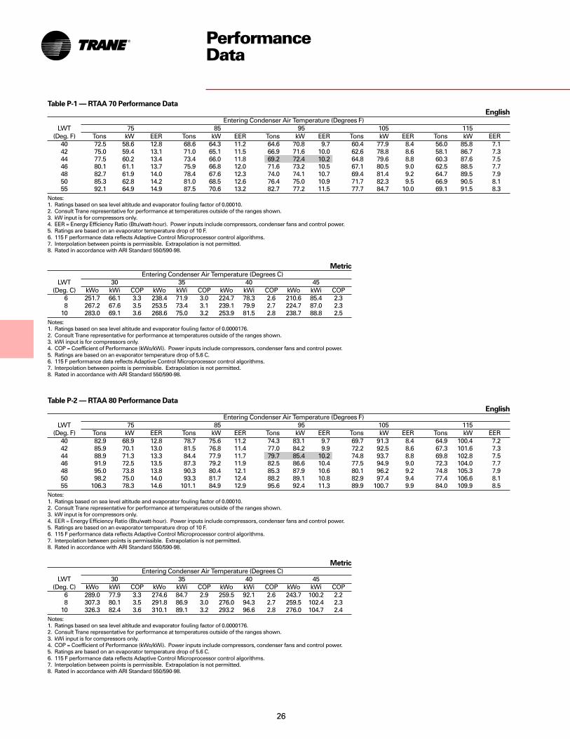
Table P-2 — RTAA 80 Performance DataEnglish
Entering Condenser Air Temperature (Degrees F)LWT 75 85 95 105 115
(Deg. F) Tons kW EER Tons kW EER Tons kW EER Tons kW EER Tons kW EER40 82.9 68.9 12.8 78.7 75.6 11.2 74.3 83.1 9.7 69.7 91.3 8.4 64.9 100.4 7.242 85.9 70.1 13.0 81.5 76.8 11.4 77.0 84.2 9.9 72.2 92.5 8.6 67.3 101.6 7.344 88.9 71.3 13.3 84.4 77.9 11.7 79.7 85.4 10.2 74.8 93.7 8.8 69.8 102.8 7.546 91.9 72.5 13.5 87.3 79.2 11.9 82.5 86.6 10.4 77.5 94.9 9.0 72.3 104.0 7.748 95.0 73.8 13.8 90.3 80.4 12.1 85.3 87.9 10.6 80.1 96.2 9.2 74.8 105.3 7.950 98.2 75.0 14.0 93.3 81.7 12.4 88.2 89.1 10.8 82.9 97.4 9.4 77.4 106.6 8.155 106.3 78.3 14.6 101.1 84.9 12.9 95.6 92.4 11.3 89.9 100.7 9.9 84.0 109.9 8.5
Notes:1. Ratings based on sea level altitude and evaporator fouling factor of 0.00010.2. Consult Trane representative for performance at temperatures outside of the ranges shown.3. kW input is for compressors only.4. EER = Energy Efficiency Ratio (Btu/watt-hour). Power inputs include compressors, condenser fans and control power.5. Ratings are based on an evaporator temperature drop of 10 F.6. 115 F performance data reflects Adaptive Control Microprocessor control algorithms.7. Interpolation between points is permissible. Extrapolation is not permitted.8. Rated in accordance with ARI Standard 550/590-98.
Table P-1 — RTAA 70 Performance DataEnglish
Entering Condenser Air Temperature (Degrees F)LWT 75 85 95 105 115
(Deg. F) Tons kW EER Tons kW EER Tons kW EER Tons kW EER Tons kW EER40 72.5 58.6 12.8 68.6 64.3 11.2 64.6 70.8 9.7 60.4 77.9 8.4 56.0 85.8 7.142 75.0 59.4 13.1 71.0 65.1 11.5 66.9 71.6 10.0 62.6 78.8 8.6 58.1 86.7 7.344 77.5 60.2 13.4 73.4 66.0 11.8 69.2 72.4 10.2 64.8 79.6 8.8 60.3 87.6 7.546 80.1 61.1 13.7 75.9 66.8 12.0 71.6 73.2 10.5 67.1 80.5 9.0 62.5 88.5 7.748 82.7 61.9 14.0 78.4 67.6 12.3 74.0 74.1 10.7 69.4 81.4 9.2 64.7 89.5 7.950 85.3 62.8 14.2 81.0 68.5 12.6 76.4 75.0 10.9 71.7 82.3 9.5 66.9 90.5 8.155 92.1 64.9 14.9 87.5 70.6 13.2 82.7 77.2 11.5 77.7 84.7 10.0 69.1 91.5 8.3
Notes:1. Ratings based on sea level altitude and evaporator fouling factor of 0.00010.2. Consult Trane representative for performance at temperatures outside of the ranges shown.3. kW input is for compressors only.4. EER = Energy Efficiency Ratio (Btu/watt-hour). Power inputs include compressors, condenser fans and control power.5. Ratings are based on an evaporator temperature drop of 10 F.6. 115 F performance data reflects Adaptive Control Microprocessor control algorithms.7. Interpolation between points is permissible. Extrapolation is not permitted.8. Rated in accordance with ARI Standard 550/590-98.
PerformanceData
MetricEntering Condenser Air Temperature (Degrees C)
LWT 30 35 40 45(Deg. C) kWo kWi COP kWo kWi COP kWo kWi COP kWo kWi COP
6 251.7 66.1 3.3 238.4 71.9 3.0 224.7 78.3 2.6 210.6 85.4 2.38 267.2 67.6 3.5 253.5 73.4 3.1 239.1 79.9 2.7 224.7 87.0 2.3
10 283.0 69.1 3.6 268.6 75.0 3.2 253.9 81.5 2.8 238.7 88.8 2.5Notes:1. Ratings based on sea level altitude and evaporator fouling factor of 0.0000176.2. Consult Trane representative for performance at temperatures outside of the ranges shown.3. kWi input is for compressors only.4. COP = Coefficient of Performance (kWo/kWi). Power inputs include compressors, condenser fans and control power.5. Ratings are based on an evaporator temperature drop of 5.6 C.6. 115 F performance data reflects Adaptive Control Microprocessor control algorithms.7. Interpolation between points is permissible. Extrapolation is not permitted.8. Rated in accordance with ARI Standard 550/590-98.
MetricEntering Condenser Air Temperature (Degrees C)
LWT 30 35 40 45(Deg. C) kWo kWi COP kWo kWi COP kWo kWi COP kWo kWi COP
6 289.0 77.9 3.3 274.6 84.7 2.9 259.5 92.1 2.6 243.7 100.2 2.28 307.3 80.1 3.5 291.8 86.9 3.0 276.0 94.3 2.7 259.5 102.4 2.3
10 326.3 82.4 3.6 310.1 89.1 3.2 293.2 96.6 2.8 276.0 104.7 2.4Notes:1. Ratings based on sea level altitude and evaporator fouling factor of 0.0000176.2. Consult Trane representative for performance at temperatures outside of the ranges shown.3. kWi input is for compressors only.4. COP = Coefficient of Performance (kWo/kWi). Power inputs include compressors, condenser fans and control power.5. Ratings are based on an evaporator temperature drop of 5.6 C.6. 115 F performance data reflects Adaptive Control Microprocessor control algorithms.7. Interpolation between points is permissible. Extrapolation is not permitted.8. Rated in accordance with ARI Standard 550/590-98.

27
PerformanceData
Table P-3 — RTAA 90 Performance DataEnglish
Entering Condenser Air Temperature (Degrees F)LWT 75 85 95 105 115
(Deg. F) Tons kW EER Tons kW EER Tons kW EER Tons kW EER Tons kW EER40 94.5 81.8 12.3 89.8 88.9 10.9 84.7 97.0 9.5 79.3 106.1 8.2 73.8 116.4 7.042 97.8 83.2 12.6 92.8 90.3 11.1 87.6 98.3 9.7 82.1 107.5 8.4 76.4 117.7 7.244 101.1 84.7 12.8 96.0 91.7 11.3 90.6 99.7 9.9 85.0 108.9 8.6 79.1 119.2 7.446 104.4 86.1 13.0 99.2 93.1 11.5 93.6 101.2 10.1 87.8 110.3 8.8 81.8 120.6 7.548 107.9 87.6 13.2 102.5 94.6 11.8 96.7 102.7 10.3 90.8 111.8 9.0 84.5 122.1 7.750 111.3 89.2 13.5 105.8 96.1 12.0 99.9 104.2 10.5 93.7 113.3 9.2 87.3 123.6 7.955 120.3 93.1 14.0 114.3 100.0 12.5 108.0 108.0 11.0 101.4 117.2 9.6 91.8 124.0 8.3
Notes:1. Ratings based on sea level altitude and evaporator fouling factor of 0.00010.2. Consult Trane representative for performance at temperatures outside of the ranges shown.3. kW input is for compressors only.4. EER = Energy Efficiency Ratio (Btu/watt-hour). Power inputs include compressors, condenser fans and control power.5. Ratings are based on an evaporator temperature drop of 10 F.6. 115 F performance data reflects Adaptive Control Microprocessor control algorithms.7. Interpolation between points is permissible. Extrapolation is not permitted.8. Rated in accordance with ARI Standard 550/590-98.
MetricEntering Condenser Air Temperature (Degrees C)
LWT 30 35 40 45(Deg. C) kWo kWi COP kWo kWi COP kWo kWi COP kWo kWi COP
6 329.1 91.6 3.3 312.2 98.9 2.9 294.6 107.1 2.5 276.4 116.2 2.28 349.1 94.2 3.3 331.6 101.5 3.0 312.9 109.7 2.6 293.9 118.8 2.3
10 369.9 96.9 3.5 351.2 104.2 3.1 331.9 112.3 2.7 311.5 121.4 2.4Notes:1. Ratings based on sea level altitude and evaporator fouling factor of 0.0000176.2. Consult Trane representative for performance at temperatures outside of the ranges shown.3. kWi input is for compressors only.4. COP = Coefficient of Performance (kWo/kWi). Power inputs include compressors, condenser fans and control power.5. Ratings are based on an evaporator temperature drop of 5.6 C.6. 115 F performance data reflects Adaptive Control Microprocessor control algorithms.7. Interpolation between points is permissible. Extrapolation is not permitted.8. Rated in accordance with ARI Standard 550/590-98.
MetricEntering Condenser Air Temperature (Degrees C)
LWT 30 35 40 45(Deg. C) kWo kWi COP kWo kWi COP kWo kWi COP kWo kWi COP
6 365.7 104.8 3.2 347.0 112.7 2.8 327.3 121.7 2.5 306.6 131.8 2.28 387.5 107.8 3.3 367.8 115.7 2.9 347.0 124.6 2.6 325.2 134.7 2.2
10 410.0 110.9 3.4 388.9 118.7 3.0 367.1 127.7 2.7 344.6 137.7 2.3Notes:1. Ratings based on sea level altitude and evaporator fouling factor of 0.0000176.2. Consult Trane representative for performance at temperatures outside of the ranges shown.3. kWi input is for compressors only.4. COP = Coefficient of Performance (kWo/kWi). Power inputs include compressors, condenser fans and control power.5. Ratings are based on an evaporator temperature drop of 5.6 C.6. 115 F performance data reflects Adaptive Control Microprocessor control algorithms.7. Interpolation between points is permissible. Extrapolation is not permitted.8. Rated in accordance with ARI Standard 550/590-98.
Table P-4 — RTAA 100 Performance DataEnglish
Entering Condenser Air Temperature (Degrees F)LWT 75 85 95 105 115
(Deg. F) Tons kW EER Tons kW EER Tons kW EER Tons kW EER Tons kW EER40 105.1 94.3 11.9 99.9 101.8 10.6 94.2 110.5 9.3 88.2 120.6 8.1 81.9 131.9 6.942 108.6 95.9 12.2 103.2 103.4 10.8 97.4 112.1 9.5 91.2 122.1 8.2 84.7 133.5 7.144 112.2 97.6 12.4 106.6 105.0 11.0 100.6 113.7 9.7 94.3 123.7 8.4 87.6 135.1 7.246 115.9 99.3 12.6 110.1 106.6 11.2 103.9 115.3 9.9 97.4 125.3 8.6 90.5 136.8 7.448 119.6 101.0 12.8 113.6 108.3 11.4 107.2 117.0 10.1 100.5 127.0 8.8 93.5 138.4 7.550 123.4 102.8 13.0 117.2 110.1 11.6 110.6 118.7 10.2 103.7 128.7 8.9 96.5 140.1 7.755 133.1 107.5 13.5 126.4 114.7 12.1 119.4 123.2 10.7 111.9 133.1 9.3 99.0 138.0 8.0
Notes:1. Ratings based on sea level altitude and evaporator fouling factor of 0.00010.2. Consult Trane representative for performance at temperatures outside of the ranges shown.3. kW input is for compressors only.4. EER = Energy Efficiency Ratio (Btu/watt-hour). Power inputs include compressors, condenser fans and control power.5. Ratings are based on an evaporator temperature drop of 10 F.6. 115 F performance data reflects Adaptive Control Microprocessor control algorithms.7. Interpolation between points is permissible. Extrapolation is not permitted.8. Rated in accordance with ARI Standard 550/590-98.

28
Table P-5 — RTAA 110 Performance DataEnglish
Entering Condenser Air Temperature (Degrees F)LWT 75 85 95 105 115
(Deg. F) Tons kW EER Tons kW EER Tons kW EER Tons kW EER Tons kW EER40 113.2 102.5 11.9 107.6 110.7 10.6 101.5 120.2 9.3 95.1 131.2 8.0 88.3 143.6 6.942 116.9 104.2 12.1 111.1 112.4 10.8 104.9 121.9 9.5 98.3 132.9 8.2 91.3 145.3 7.044 120.7 106.0 12.4 114.7 114.1 11.0 108.3 123.7 9.7 101.6 134.6 8.4 94.4 147.1 7.246 124.6 107.9 12.6 118.4 115.9 11.2 111.9 125.4 9.8 104.9 136.4 8.6 97.6 148.9 7.348 128.6 109.7 12.8 122.2 117.8 11.4 115.4 127.3 10.0 108.3 138.2 8.7 100.5 150.5 7.550 132.6 111.7 12.9 126.0 119.7 11.6 119.1 129.2 10.2 111.7 140.1 8.9 102.3 150.3 7.655 142.9 116.7 13.4 135.9 124.6 12.0 128.4 134.0 10.6 120.4 144.9 9.3 105.0 147.4 8.0
Notes:1. Ratings based on sea level altitude and evaporator fouling factor of 0.00010.2. Consult Trane representative for performance at temperatures outside of the ranges shown.3. kW input is for compressors only.4. EER = Energy Efficiency Ratio (Btu/watt-hour). Power inputs include compressors, condenser fans and control power.5. Ratings are based on an evaporator temperature drop of 10 F.6. 115 F performance data reflects Adaptive Control Microprocessor control algorithms.7. Interpolation between points is permissible. Extrapolation is not permitted.8. Rated in accordance with ARI Standard 550/590-98.
Table P-6 — RTAA 125 Performance DataEnglish
Entering Condenser Air Temperature (Degrees F)LWT 75 85 95 105 115
(Deg. F) Tons kW EER Tons kW EER Tons kW EER Tons kW EER Tons kW EER40 125.2 113.0 12.1 118.9 121.9 10.7 112.0 132.2 9.4 104.8 144.0 8.1 97.2 157.4 6.942 129.4 115.0 12.3 122.8 123.8 10.9 115.8 134.1 9.6 108.4 145.9 8.3 100.5 159.4 7.144 133.6 117.1 12.5 126.8 125.8 11.1 119.6 136.1 9.8 112.0 147.9 8.5 103.9 161.4 7.346 138.0 119.1 12.7 130.9 127.9 11.3 123.5 138.1 9.9 115.6 150.0 8.6 106.3 162.0 7.448 142.4 121.3 12.9 135.1 130.0 11.5 127.5 140.2 10.1 119.4 152.0 8.8 107.1 160.6 7.550 146.8 123.5 13.1 139.4 132.1 11.7 131.5 142.4 10.3 123.1 154.2 9.0 107.6 158.4 7.655 158.4 129.2 13.5 150.3 137.8 12.1 141.7 147.9 10.7 132.7 159.6 9.4 109.4 152.6 8.1
Notes:1. Ratings based on sea level altitude and evaporator fouling factor of 0.00010.2. Consult Trane representative for performance at temperatures outside of the ranges shown.3. kW input is for compressors only.4. EER = Energy Efficiency Ratio (Btu/watt-hour). Power inputs include compressors, condenser fans and control power.5. Ratings are based on an evaporator temperature drop of 10 F.6. 115 F performance data reflects Adaptive Control Microprocessor control algorithms.7. Interpolation between points is permissible. Extrapolation is not permitted.8. Rated in accordance with ARI Standard 550/590-98.
PerformanceData
MetricEntering Condenser Air Temperature (Degrees C)
LWT 30 35 40 45(Deg. C) kWo kWi COP kWo kWi COP kWo kWi COP kWo kWi COP
6 393.8 114.0 3.1 373.8 122.6 2.8 352.7 132.4 2.5 330.5 143.4 2.18 417.0 117.2 3.3 395.9 125.8 2.9 373.8 135.6 2.5 350.5 146.6 2.2
10 440.9 120.6 3.3 418.8 129.2 3.0 395.2 138.9 2.6 370.9 149.9 2.3Notes:1. Ratings based on sea level altitude and evaporator fouling factor of 0.0000176.2. Consult Trane representative for performance at temperatures outside of the ranges shown.3. kWi input is for compressors only.4. COP = Coefficient of Performance (kWo/kWi). Power inputs include compressors, condenser fans and control power.5. Ratings are based on an evaporator temperature drop of 5.6 C.6. 115 F performance data reflects Adaptive Control Microprocessor control algorithms.7. Interpolation between points is permissible. Extrapolation is not permitted.8. Rated in accordance with ARI Standard 550/590-98.
MetricEntering Condenser Air Temperature (Degrees C)
LWT 30 35 40 45(Deg. C) kWo kWi COP kWo kWi COP kWo kWi COP kWo kWi COP
6 434.9 125.6 3.2 412.4 134.9 2.8 388.9 145.5 2.5 363.9 157.4 2.28 460.9 129.2 3.3 437.0 138.5 2.9 412.1 149.1 2.6 386.1 161.0 2.3
10 487.3 133.1 3.4 462.4 142.4 3.0 436.0 152.9 2.7 408.6 164.8 2.3Notes:1. Ratings based on sea level altitude and evaporator fouling factor of 0.0000176.2. Consult Trane representative for performance at temperatures outside of the ranges shown.3. kWi input is for compressors only.4. COP = Coefficient of Performance (kWo/kWi). Power inputs include compressors, condenser fans and control power.5. Ratings are based on an evaporator temperature drop of 5.6 C.6. 115 F performance data reflects Adaptive Control Microprocessor control algorithms.7. Interpolation between points is permissible. Extrapolation is not permitted.8. Rated in accordance with ARI Standard 550/590-98.

29
Table P-7 — RTAA 130 Performance DataEnglish
Entering Condenser Air Temperature (Degrees F)LWT 75 85 95 105 115
(Deg. F) Tons kW EER Tons kW EER Tons kW EER Tons kW EER Tons kW EER40 138.3 122.5 12.2 131.0 135.0 10.6 123.3 149.6 9.1 115.3 166.1 7.7 107.0 184.7 6.542 143.2 124.5 12.4 135.6 137.2 10.8 127.7 151.8 9.3 119.4 168.4 7.9 110.8 187.0 6.644 148.2 126.6 12.7 140.4 139.4 11.0 132.2 154.0 9.5 123.6 170.7 8.1 114.7 189.4 6.846 153.2 128.8 12.9 145.2 141.6 11.2 136.7 156.4 9.7 127.9 173.1 8.2 118.7 191.9 7.048 158.4 131.0 13.1 150.1 143.9 11.4 141.4 158.8 9.9 132.3 175.6 8.4 122.7 194.4 7.150 163.6 133.3 13.3 155.1 146.3 11.6 146.1 161.2 10.0 136.7 178.1 8.6 125.2 193.5 7.355 177.1 139.3 13.9 168.0 152.5 12.1 158.3 167.7 10.5 148.1 184.8 9.0 127.8 183.9 7.8
Notes:1. Ratings based on sea level altitude and evaporator fouling factor of 0.00010.2. Consult Trane representative for performance at temperatures outside of the ranges shown.3. kW input is for compressors only.4. EER = Energy Efficiency Ratio (Btu/watt-hour). Power inputs include compressors, condenser fans and control power.5. Ratings are based on an evaporator temperature drop of 10 F.6. 115 F performance data reflects Adaptive Control Microprocessor control algorithms.7. Interpolation between points is permissible. Extrapolation is not permitted.8. Rated in accordance with ARI Standard 550/590-98.
Table P-8 — RTAA 140 Performance DataEnglish
Entering Condenser Air Temperature (Degrees F)LWT 75 85 95 105 115
(Deg. F) Tons kW EER Tons kW EER Tons kW EER Tons kW EER Tons kW EER40 149.6 132.4 12.3 141.5 146.0 10.6 133.1 161.7 9.1 124.4 179.5 7.7 115.3 199.5 6.542 154.8 134.6 12.5 146.5 148.4 10.9 137.8 164.2 9.3 128.7 182.1 7.9 119.3 202.1 6.744 160.1 137.0 12.7 151.5 150.8 11.1 142.6 166.7 9.5 133.2 184.7 8.1 121.8 201.1 6.846 165.5 139.4 13.0 156.7 153.3 11.3 147.4 169.3 9.7 137.7 187.3 8.2 124.2 200.0 7.048 171.0 141.8 13.2 161.9 155.8 11.5 152.3 171.9 9.9 142.3 190.1 8.4 124.9 195.2 7.250 176.6 144.4 13.4 167.2 158.5 11.7 157.4 174.6 10.0 147.0 192.9 8.6 125.6 190.3 7.455 191.0 151.0 13.9 180.9 165.4 12.1 170.2 181.8 10.5 159.1 200.3 8.9 128.8 181.4 8.0
Notes:1. Ratings based on sea level altitude and evaporator fouling factor of 0.00010.2. Consult Trane representative for performance at temperatures outside of the ranges shown.3. kW input is for compressors only.4. EER = Energy Efficiency Ratio (Btu/watt-hour). Power inputs include compressors, condenser fans and control power.5. Ratings are based on an evaporator temperature drop of 10 F.6. 115 F performance data reflects Adaptive Control Microprocessor control algorithms.7. Interpolation between points is permissible. Extrapolation is not permitted.8. Rated in accordance with ARI Standard 550/590-98.
PerformanceData
MetricEntering Condenser Air Temperature (Degrees C)
LWT 30 35 40 45(Deg. C) kWo kWi COP kWo kWi COP kWo kWi COP kWo kWi COP
6 480.6 139.4 3.1 455.3 152.7 2.8 429.0 167.5 2.4 401.5 184.1 2.18 510.9 143.5 3.3 484.2 156.8 2.8 456.0 171.8 2.5 426.8 188.5 2.1
10 542.2 147.7 3.4 513.7 161.2 2.9 484.2 176.4 2.5 453.2 193.1 2.2Notes:1. Ratings based on sea level altitude and evaporator fouling factor of 0.0000176.2. Consult Trane representative for performance at temperatures outside of the ranges shown.3. kWi input is for compressors only.4. COP = Coefficient of Performance (kWo/kWi). Power inputs include compressors, condenser fans and control power.5. Ratings are based on an evaporator temperature drop of 5.6 C.6. 115 F performance data reflects Adaptive Control Microprocessor control algorithms.7. Interpolation between points is permissible. Extrapolation is not permitted.8. Rated in accordance with ARI Standard 550/590-98.
MetricEntering Condenser Air Temperature (Degrees C)
LWT 30 35 40 45(Deg. C) kWo kWi COP kWo kWi COP kWo kWi COP kWo kWi COP
6 519.3 150.8 3.2 491.2 165.2 2.8 462.4 181.2 2.4 432.1 199.0 2.18 551.3 155.3 3.3 521.8 169.8 2.8 491.2 186.0 2.5 459.2 203.9 2.1
10 584.7 160.0 3.4 553.4 174.6 2.9 520.7 191.0 2.5 474.3 201.4 2.2Notes:1. Ratings based on sea level altitude and evaporator fouling factor of 0.0000176.2. Consult Trane representative for performance at temperatures outside of the ranges shown.3. kWi input is for compressors only.4. COP = Coefficient of Performance (kWo/kWi). Power inputs include compressors, condenser fans and control power.5. Ratings are based on an evaporator temperature drop of 5.6 C.6. 115 F performance data reflects Adaptive Control Microprocessor control algorithms.7. Interpolation between points is permissible. Extrapolation is not permitted.8. Rated in accordance with ARI Standard 550/590-98.

30
PerformanceData
Table P-9 — RTAA 155 Performance DataEnglish
Entering Condenser Air Temperature (Degrees F)LWT 75 85 95 105 115
(Deg. F) Tons kW EER Tons kW EER Tons kW EER Tons kW EER Tons kW EER40 156.7 141.1 12.0 148.8 155.9 10.5 140.5 172.7 9.0 131.7 191.6 7.7 122.6 212.5 6.542 162.6 143.5 12.3 154.4 158.4 10.7 145.7 175.3 9.2 136.6 194.2 7.9 127.1 215.2 6.744 168.5 146.0 12.5 160.0 161.0 10.9 151.0 178.0 9.4 141.6 197.0 8.0 131.8 218.0 6.846 174.5 148.5 12.8 165.8 163.6 11.1 156.5 180.7 9.6 146.7 199.8 8.2 132.9 213.3 7.048 180.7 151.1 13.0 171.6 166.3 11.4 162.0 183.5 9.8 151.9 202.7 8.4 134.7 210.4 7.250 186.9 153.8 13.3 177.6 169.1 11.6 167.7 186.4 10.0 157.2 205.6 8.6 135.6 205.6 7.455 203.0 160.7 13.9 192.9 176.3 12.1 182.1 193.9 10.5 170.7 213.4 9.0 139.1 196.5 7.9
Notes:1. Ratings based on sea level altitude and evaporator fouling factor of 0.00010.2. Consult Trane representative for performance at temperatures outside of the ranges shown.3. kW input is for compressors only.4. EER = Energy Efficiency Ratio (Btu/watt-hour). Power inputs include compressors, condenser fans and control power.5. Ratings are based on an evaporator temperature drop of 10 F.6. 115 F performance data reflects Adaptive Control Microprocessor control algorithms.7. Interpolation between points is permissible. Extrapolation is not permitted.8. Rated in accordance with ARI Standard 550/590-98.
MetricEntering Condenser Air Temperature (Degrees C)
LWT 30 35 40 45(Deg. C) kWo kWi COP kWo kWi COP kWo kWi COP kWo kWi COP
6 547.8 161.0 3.1 519.7 176.4 2.7 490.8 193.3 2.4 460.2 212.0 2.08 583.7 165.8 3.2 554.1 181.3 2.8 523.2 198.4 2.5 490.5 217.1 2.1
10 620.9 170.7 3.3 589.6 186.4 2.9 556.2 203.6 2.5 513.3 217.7 2.2Notes:1. Ratings based on sea level altitude and evaporator fouling factor of 0.0000176.2. Consult Trane representative for performance at temperatures outside of the ranges shown.3. kWi input is for compressors only.4. COP = Coefficient of Performance (kWo/kWi). Power inputs include compressors, condenser fans and control power.5. Ratings are based on an evaporator temperature drop of 5.6 C.6. 115 F performance data reflects Adaptive Control Microprocessor control algorithms.7. Interpolation between points is permissible. Extrapolation is not permitted.8. Rated in accordance with ARI Standard 550/590-98.
MetricEntering Condenser Air Temperature (Degrees C)
LWT 30 35 40 45(Deg. C) kWo kWi COP kWo kWi COP kWo kWi COP kWo kWi COP
6 601.9 181.8 3.0 572.4 198.3 2.7 541.8 216.7 2.3 499.3 230.6 2.08 639.2 187.5 3.1 607.9 204.2 2.8 575.6 222.8 2.4 514.7 227.5 2.1
10 677.5 193.5 3.2 644.5 210.3 2.8 610.4 229.1 2.5 530.9 224.5 2.2Notes:1. Ratings based on sea level altitude and evaporator fouling factor of 0.0000176.2. Consult Trane representative for performance at temperatures outside of the ranges shown.3. kWi input is for compressors only.4. COP = Coefficient of Performance (kWo/kWi). Power inputs include compressors, condenser fans and control power.5. Ratings are based on an evaporator temperature drop of 5.6 C.6. 115 F performance data reflects Adaptive Control Microprocessor control algorithms.7. Interpolation between points is permissible. Extrapolation is not permitted.8. Rated in accordance with ARI Standard 550/590-98.
Table P-10 — RTAA 170 Performance DataEnglish
Entering Condenser Air Temperature (Degrees F)LWT 75 85 95 105 115
(Deg. F) Tons kW EER Tons kW EER Tons kW EER Tons kW EER Tons kW EER40 172.9 160.2 11.7 164.1 175.9 10.3 155.1 193.9 8.9 145.9 214.3 7.6 131.2 226.5 6.542 178.9 163.1 12.0 169.8 178.9 10.4 160.5 197.0 9.1 151.1 217.5 7.8 133.8 225.3 6.744 185.0 166.1 12.2 175.6 182.0 10.6 166.1 200.2 9.2 156.3 220.9 7.9 136.2 224.0 6.846 191.2 169.2 12.4 181.6 185.2 10.8 171.7 203.5 9.4 161.6 224.3 8.1 137.0 218.8 7.048 197.6 172.4 12.6 187.6 188.4 11.0 177.4 206.9 9.6 167.0 227.7 8.2 138.9 215.7 7.250 204.0 175.6 12.8 193.7 191.8 11.2 183.3 210.3 9.7 172.5 231.3 8.4 140.4 212.0 7.455 220.5 184.0 13.2 209.5 200.4 11.6 198.2 219.3 10.1 186.7 240.6 8.8 143.7 201.7 7.9
Notes:1. Ratings based on sea level altitude and evaporator fouling factor of 0.00010.2. Consult Trane representative for performance at temperatures outside of the ranges shown.3. kW input is for compressors only.4. EER = Energy Efficiency Ratio (Btu/watt-hour). Power inputs include compressors, condenser fans and control power.5. Ratings are based on an evaporator temperature drop of 10 F.6. 115 F performance data reflects Adaptive Control Microprocessor control algorithms.7. Interpolation between points is permissible. Extrapolation is not permitted.8. Rated in accordance with ARI Standard 550/590-98.
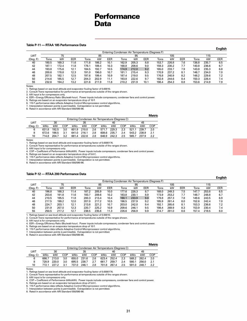
31
PerformanceData
Table P-11 — RTAA 185 Performance DataEnglish
Entering Condenser Air Temperature (Degrees F)LWT 75 85 95 105 115
(Deg. F) Tons kW EER Tons kW EER Tons kW EER Tons kW EER Tons kW EER40 180.5 169.3 11.6 171.8 186.2 10.1 162.9 205.3 8.8 153.7 226.8 7.6 136.8 235.7 6.542 187.1 172.4 11.8 178.1 189.4 10.3 168.8 208.6 9.0 159.3 230.2 7.7 140.8 236.6 6.744 193.8 175.6 12.1 184.5 192.7 10.5 174.9 212.0 9.2 165.0 233.7 7.9 143.8 235.3 6.846 200.6 178.8 12.3 191.0 196.0 10.7 181.1 215.4 9.3 170.9 237.2 8.1 146.7 234.0 7.048 207.5 182.1 12.5 197.6 199.4 10.9 187.4 219.0 9.5 176.8 240.9 8.2 148.2 229.6 7.250 214.6 185.5 12.7 204.3 202.9 11.1 193.8 222.6 9.7 182.8 244.6 8.4 150.3 226.4 7.455 232.6 194.2 13.2 221.6 211.9 11.6 210.2 231.9 10.1 198.4 254.3 8.8 153.6 214.9 7.9
Notes:1. Ratings based on sea level altitude and evaporator fouling factor of 0.00010.2. Consult Trane representative for performance at temperatures outside of the ranges shown.3. kW input is for compressors only.4. EER = Energy Efficiency Ratio (Btu/watt-hour). Power inputs include compressors, condenser fans and control power.5. Ratings are based on an evaporator temperature drop of 10 F.6. 115 F performance data reflects Adaptive Control Microprocessor control algorithms.7. Interpolation between points is permissible. Extrapolation is not permitted.8. Rated in accordance with ARI Standard 550/590-98.
MetricEntering Condenser Air Temperature (Degrees C)
LWT 30 35 40 45(Deg. C) kWo kWi COP kWo kWi COP kWo kWi COP kWo kWi COP
6 631.8 192.5 3.0 601.9 210.0 2.6 571.7 229.3 2.3 521.1 239.7 2.08 672.6 198.5 3.1 641.0 216.1 2.8 608.6 235.7 2.4 543.2 238.9 2.1
10 714.8 204.7 3.2 681.4 222.6 2.8 646.9 242.3 2.5 565.7 237.9 2.2Notes:1. Ratings based on sea level altitude and evaporator fouling factor of 0.0000176.2. Consult Trane representative for performance at temperatures outside of the ranges shown.3. kWi input is for compressors only.4. COP = Coefficient of Performance (kWo/kWi). Power inputs include compressors, condenser fans and control power.5. Ratings are based on an evaporator temperature drop of 5.6 C.6. 115 F performance data reflects Adaptive Control Microprocessor control algorithms.7. Interpolation between points is permissible. Extrapolation is not permitted.8. Rated in accordance with ARI Standard 550/590-98.
MetricEntering Condenser Air Temperature (Degrees C)
LWT 30 35 40 45(Deg. C) kWo kWi COP kWo kWi COP kWo kWi COP kWo kWi COP
6 686.7 213.0 3.0 655.0 231.6 2.6 623.4 252.4 2.3 568.2 262.4 2.08 728.9 220.0 3.0 695.5 238.7 2.7 661.7 259.7 2.4 580.1 256.0 2.1
10 772.1 227.2 3.1 737.0 246.1 2.8 701.8 267.4 2.5 591.0 248.7 2.2Notes:1. Ratings based on sea level altitude and evaporator fouling factor of 0.0000176.2. Consult Trane representative for performance at temperatures outside of the ranges shown.3. kWi input is for compressors only.4. COP = Coefficient of Performance (kWo/kWi). Power inputs include compressors, condenser fans and control power.5. Ratings are based on an evaporator temperature drop of 5.6 C.6. 115 F performance data reflects Adaptive Control Microprocessor control algorithms.7. Interpolation between points is permissible. Extrapolation is not permitted.8. Rated in accordance with ARI Standard 550/590-98.
Table P-12 — RTAA 200 Performance DataEnglish
Entering Condenser Air Temperature (Degrees F)LWT 75 85 95 105 115
(Deg. F) Tons kW EER Tons kW EER Tons kW EER Tons kW EER Tons kW EER40 196.8 188.3 11.4 187.2 205.9 10.0 177.6 226.3 8.7 168.0 249.3 7.5 147.7 253.8 6.542 203.6 191.8 11.6 193.7 209.6 10.2 183.8 230.1 8.9 173.9 253.2 7.7 148.7 248.8 6.744 210.5 195.5 11.8 200.3 213.4 10.4 190.1 233.9 9.0 179.8 257.3 7.8 149.6 243.5 6.946 217.5 199.2 12.0 207.0 217.2 10.5 196.5 237.9 9.2 185.9 261.4 8.0 152.6 242.4 7.048 224.7 203.1 12.1 213.8 221.2 10.7 203.0 242.0 9.4 192.1 265.6 8.1 153.3 236.6 7.250 231.9 207.0 12.3 220.7 225.2 10.9 209.6 246.1 9.5 198.4 269.9 8.3 153.9 230.4 7.455 250.5 217.2 12.7 238.5 235.6 11.3 226.6 256.9 9.9 214.7 281.0 8.6 157.4 218.5 8.0
1. Ratings based on sea level altitude and evaporator fouling factor of 0.00010.2. Consult Trane representative for performance at temperatures outside of the ranges shown.3. kW input is for compressors only.4. EER = Energy Efficiency Ratio (Btu/watt-hour). Power inputs include compressors, condenser fans and control power.5. Ratings are based on an evaporator temperature drop of 10 F.6. 115 F performance data reflects Adaptive Control Microprocessor control algorithms.7. Interpolation between points is permissible. Extrapolation is not permitted.8. Rated in accordance with ARI Standard 550/590-98.
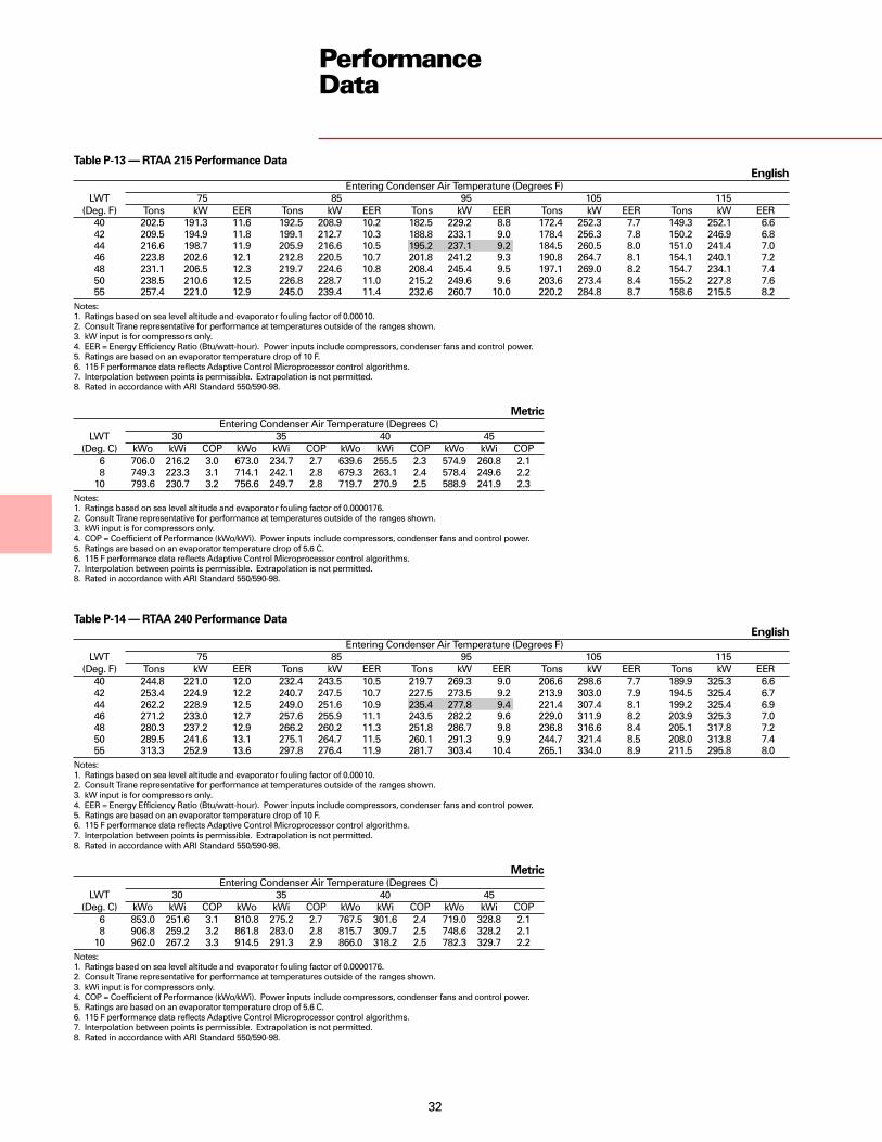
32
PerformanceData
Table P-13 — RTAA 215 Performance DataEnglish
Entering Condenser Air Temperature (Degrees F)LWT 75 85 95 105 115
(Deg. F) Tons kW EER Tons kW EER Tons kW EER Tons kW EER Tons kW EER40 202.5 191.3 11.6 192.5 208.9 10.2 182.5 229.2 8.8 172.4 252.3 7.7 149.3 252.1 6.642 209.5 194.9 11.8 199.1 212.7 10.3 188.8 233.1 9.0 178.4 256.3 7.8 150.2 246.9 6.844 216.6 198.7 11.9 205.9 216.6 10.5 195.2 237.1 9.2 184.5 260.5 8.0 151.0 241.4 7.046 223.8 202.6 12.1 212.8 220.5 10.7 201.8 241.2 9.3 190.8 264.7 8.1 154.1 240.1 7.248 231.1 206.5 12.3 219.7 224.6 10.8 208.4 245.4 9.5 197.1 269.0 8.2 154.7 234.1 7.450 238.5 210.6 12.5 226.8 228.7 11.0 215.2 249.6 9.6 203.6 273.4 8.4 155.2 227.8 7.655 257.4 221.0 12.9 245.0 239.4 11.4 232.6 260.7 10.0 220.2 284.8 8.7 158.6 215.5 8.2
Notes:1. Ratings based on sea level altitude and evaporator fouling factor of 0.00010.2. Consult Trane representative for performance at temperatures outside of the ranges shown.3. kW input is for compressors only.4. EER = Energy Efficiency Ratio (Btu/watt-hour). Power inputs include compressors, condenser fans and control power.5. Ratings are based on an evaporator temperature drop of 10 F.6. 115 F performance data reflects Adaptive Control Microprocessor control algorithms.7. Interpolation between points is permissible. Extrapolation is not permitted.8. Rated in accordance with ARI Standard 550/590-98.
MetricEntering Condenser Air Temperature (Degrees C)
LWT 30 35 40 45(Deg. C) kWo kWi COP kWo kWi COP kWo kWi COP kWo kWi COP
6 706.0 216.2 3.0 673.0 234.7 2.7 639.6 255.5 2.3 574.9 260.8 2.18 749.3 223.3 3.1 714.1 242.1 2.8 679.3 263.1 2.4 578.4 249.6 2.2
10 793.6 230.7 3.2 756.6 249.7 2.8 719.7 270.9 2.5 588.9 241.9 2.3Notes:1. Ratings based on sea level altitude and evaporator fouling factor of 0.0000176.2. Consult Trane representative for performance at temperatures outside of the ranges shown.3. kWi input is for compressors only.4. COP = Coefficient of Performance (kWo/kWi). Power inputs include compressors, condenser fans and control power.5. Ratings are based on an evaporator temperature drop of 5.6 C.6. 115 F performance data reflects Adaptive Control Microprocessor control algorithms.7. Interpolation between points is permissible. Extrapolation is not permitted.8. Rated in accordance with ARI Standard 550/590-98.
MetricEntering Condenser Air Temperature (Degrees C)
LWT 30 35 40 45(Deg. C) kWo kWi COP kWo kWi COP kWo kWi COP kWo kWi COP
6 853.0 251.6 3.1 810.8 275.2 2.7 767.5 301.6 2.4 719.0 328.8 2.18 906.8 259.2 3.2 861.8 283.0 2.8 815.7 309.7 2.5 748.6 328.2 2.1
10 962.0 267.2 3.3 914.5 291.3 2.9 866.0 318.2 2.5 782.3 329.7 2.2Notes:1. Ratings based on sea level altitude and evaporator fouling factor of 0.0000176.2. Consult Trane representative for performance at temperatures outside of the ranges shown.3. kWi input is for compressors only.4. COP = Coefficient of Performance (kWo/kWi). Power inputs include compressors, condenser fans and control power.5. Ratings are based on an evaporator temperature drop of 5.6 C.6. 115 F performance data reflects Adaptive Control Microprocessor control algorithms.7. Interpolation between points is permissible. Extrapolation is not permitted.8. Rated in accordance with ARI Standard 550/590-98.
Table P-14 — RTAA 240 Performance DataEnglish
Entering Condenser Air Temperature (Degrees F)LWT 75 85 95 105 115
(Deg. F) Tons kW EER Tons kW EER Tons kW EER Tons kW EER Tons kW EER40 244.8 221.0 12.0 232.4 243.5 10.5 219.7 269.3 9.0 206.6 298.6 7.7 189.9 325.3 6.642 253.4 224.9 12.2 240.7 247.5 10.7 227.5 273.5 9.2 213.9 303.0 7.9 194.5 325.4 6.744 262.2 228.9 12.5 249.0 251.6 10.9 235.4 277.8 9.4 221.4 307.4 8.1 199.2 325.4 6.946 271.2 233.0 12.7 257.6 255.9 11.1 243.5 282.2 9.6 229.0 311.9 8.2 203.9 325.3 7.048 280.3 237.2 12.9 266.2 260.2 11.3 251.8 286.7 9.8 236.8 316.6 8.4 205.1 317.8 7.250 289.5 241.6 13.1 275.1 264.7 11.5 260.1 291.3 9.9 244.7 321.4 8.5 208.0 313.8 7.455 313.3 252.9 13.6 297.8 276.4 11.9 281.7 303.4 10.4 265.1 334.0 8.9 211.5 295.8 8.0
Notes:1. Ratings based on sea level altitude and evaporator fouling factor of 0.00010.2. Consult Trane representative for performance at temperatures outside of the ranges shown.3. kW input is for compressors only.4. EER = Energy Efficiency Ratio (Btu/watt-hour). Power inputs include compressors, condenser fans and control power.5. Ratings are based on an evaporator temperature drop of 10 F.6. 115 F performance data reflects Adaptive Control Microprocessor control algorithms.7. Interpolation between points is permissible. Extrapolation is not permitted.8. Rated in accordance with ARI Standard 550/590-98.

33
PerformanceData
Table P-15 — RTAA 270 Performance DataEnglish
Entering Condenser Air Temperature (Degrees F)LWT 75 85 95 105 115
(Deg. F) Tons kW EER Tons kW EER Tons kW EER Tons kW EER Tons kW EER40 271.1 249.2 11.8 257.8 273.6 10.3 244.2 301.8 9.0 230.4 333.7 7.7 212.1 361.0 6.642 280.6 253.7 12.0 266.8 278.3 10.5 252.8 306.6 9.1 238.6 338.7 7.9 215.6 357.9 6.844 290.2 258.4 12.2 276.0 283.1 10.7 261.6 311.6 9.3 246.9 343.9 8.0 217.1 350.7 6.946 300.1 263.2 12.4 285.4 288.1 10.9 270.5 316.7 9.5 255.3 349.1 8.2 219.7 345.4 7.148 310.1 268.1 12.6 294.9 293.1 11.1 279.5 321.9 9.7 263.9 354.6 8.3 222.9 341.5 7.350 320.2 273.1 12.8 304.6 298.3 11.3 288.8 327.3 9.8 272.6 360.1 8.5 224.1 333.4 7.555 346.3 286.2 13.3 329.5 311.8 11.7 312.5 341.2 10.2 295.2 374.6 8.9 229.8 318.1 8.0
Notes:1. Ratings based on sea level altitude and evaporator fouling factor of 0.00010.2. Consult Trane representative for performance at temperatures outside of the ranges shown.3. kW input is for compressors only.4. EER = Energy Efficiency Ratio (Btu/watt-hour). Power inputs include compressors, condenser fans and control power.5. Ratings are based on an evaporator temperature drop of 10 F.6. 115 F performance data reflects Adaptive Control Microprocessor control algorithms.7. Interpolation between points is permissible. Extrapolation is not permitted.8. Rated in accordance with ARI Standard 550/590-98.
MetricEntering Condenser Air Temperature (Degrees C)
LWT 30 35 40 45(Deg. C) kWo kWi COP kWo kWi COP kWo kWi COP kWo kWi COP
6 945.8 282.9 3.1 901.2 308.6 2.7 855.4 337.3 2.4 801.3 365.0 2.18 1004.9 291.7 3.2 957.1 317.7 2.8 908.9 346.8 2.4 839.6 367.9 2.1
10 1065.4 301.0 3.3 1015.1 327.3 2.9 964.1 356.7 2.5 845.6 352.0 2.3Notes:1. Ratings based on sea level altitude and evaporator fouling factor of 0.0000176.2. Consult Trane representative for performance at temperatures outside of the ranges shown.3. kWi input is for compressors only.4. COP = Coefficient of Performance (kWo/kWi). Power inputs include compressors, condenser fans and control power.5. Ratings are based on an evaporator temperature drop of 5.6 C.6. 115 F performance data reflects Adaptive Control Microprocessor control algorithms.7. Interpolation between points is permissible. Extrapolation is not permitted.8. Rated in accordance with ARI Standard 550/590-98.
MetricEntering Condenser Air Temperature (Degrees C)
LWT 30 35 40 45(Deg. C) kWo kWi COP kWo kWi COP kWo kWi COP kWo kWi COP
6 1037.6 314.9 3.0 990.1 342.7 2.7 942.6 373.9 2.3 879.7 399.9 2.18 1101.6 325.1 3.1 1051.6 353.2 2.8 1001.4 384.7 2.4 891.3 386.6 2.2
10 1167.3 335.7 3.2 1114.6 364.1 2.8 1061.8 396.0 2.5 905.0 374.0 2.3Notes:1. Ratings based on sea level altitude and evaporator fouling factor of 0.0000176.2. Consult Trane representative for performance at temperatures outside of the ranges shown.3. kWi input is for compressors only.4. COP = Coefficient of Performance (kWo/kWi). Power inputs include compressors, condenser fans and control power.5. Ratings are based on an evaporator temperature drop of 5.6 C.6. 115 F performance data reflects Adaptive Control Microprocessor control algorithms.7. Interpolation between points is permissible. Extrapolation is not permitted.8. Rated in accordance with ARI Standard 550/590-98.
Table P-16 — RTAA 300 Performance DataEnglish
Entering Condenser Air Temperature (Degrees F)LWT 75 85 95 105 115
(Deg. F) Tons kW EER Tons kW EER Tons kW EER Tons kW EER Tons kW EER40 297.0 278.0 11.6 282.8 304.5 10.2 268.5 334.9 8.9 254.1 369.4 7.7 229.1 387.3 6.642 307.3 283.2 11.8 292.6 309.9 10.4 277.9 340.5 9.0 263.0 375.2 7.8 230.8 380.1 6.844 317.8 288.6 12.0 302.6 315.4 10.6 287.4 346.2 9.2 272.1 381.1 8.0 232.4 372.6 7.046 328.5 294.0 12.2 312.8 321.0 10.7 297.1 352.0 9.4 281.3 387.2 8.1 233.8 364.6 7.248 339.3 299.7 12.4 323.2 326.8 10.9 307.0 358.0 9.5 290.7 393.4 8.3 236.3 358.5 7.450 350.3 305.4 12.6 333.7 332.7 11.1 317.0 364.1 9.7 300.3 399.8 8.4 237.4 349.6 7.655 378.6 320.4 13.0 360.7 348.1 11.5 342.9 380.0 10.1 325.0 416.2 8.8 243.0 332.5 8.1
Notes:1. Ratings based on sea level altitude and evaporator fouling factor of 0.00010.2. Consult Trane representative for performance at temperatures outside of the ranges shown.3. kW input is for compressors only.4. EER = Energy Efficiency Ratio (Btu/watt-hour). Power inputs include compressors, condenser fans and control power.5. Ratings are based on an evaporator temperature drop of 10 F.6. 115 F performance data reflects Adaptive Control Microprocessor control algorithms.7. Interpolation between points is permissible. Extrapolation is not permitted.8. Rated in accordance with ARI Standard 550/590-98.

34
PerformanceData
Table P-17 — RTAA 340 Performance DataEnglish
Entering Condenser Air Temperature (Degrees F)LWT 75 85 95 105 115
(Deg. F) Tons kW EER Tons kW EER Tons kW EER Tons kW EER Tons kW EER40 345.9 314.3 11.9 328.7 345.6 10.4 311.2 381.5 9.0 293.2 422.3 7.7 268.5 455.7 6.642 358.1 319.9 12.2 340.4 351.4 10.6 322.2 387.6 9.2 303.6 428.6 7.9 273.8 453.5 6.844 370.5 325.7 12.4 352.2 357.4 10.8 333.4 393.8 9.4 314.2 435.0 8.1 279.2 451.1 6.946 383.1 331.7 12.6 364.2 363.5 11.0 344.9 400.1 9.6 325.0 441.6 8.2 284.4 448.5 7.148 396.0 337.8 12.8 376.5 369.9 11.2 356.5 406.7 9.7 336.1 448.4 8.4 286.1 438.2 7.350 409.0 344.1 13.0 389.0 376.3 11.4 368.4 413.4 9.9 347.3 455.3 8.6 287.6 427.6 7.555 442.6 360.4 13.5 421.0 393.2 11.9 398.9 430.8 10.3 376.2 473.4 8.9 295.0 407.6 8.1
Notes:1. Ratings based on sea level altitude and evaporator fouling factor of 0.00010.2. Consult Trane representative for performance at temperatures outside of the ranges shown.3. kW input is for compressors only.4. EER = Energy Efficiency Ratio (Btu/watt-hour). Power inputs include compressors, condenser fans and control power.5. Ratings are based on an evaporator temperature drop of 10 F.6. 115 F performance data reflects Adaptive Control Microprocessor control algorithms.7. Interpolation between points is permissible. Extrapolation is not permitted.8. Rated in accordance with ARI Standard 550/590-98.
MetricEntering Condenser Air Temperature (Degrees C)
LWT 30 35 40 45(Deg. C) kWo kWi COP kWo kWi COP kWo kWi COP kWo kWi COP
6 1206.7 357.2 3.1 1148.3 390.0 2.7 1088.9 426.8 2.4 1020.7 463.4 2.18 1282.3 368.2 3.2 1220.8 401.4 2.8 1157.5 438.6 2.5 1053.4 457.9 2.1
10 1360.3 379.8 3.3 1295.3 413.4 2.9 1228.5 450.9 2.5 1094.2 456.0 2.3Notes:1. Ratings based on sea level altitude and evaporator fouling factor of 0.0000176.2. Consult Trane representative for performance at temperatures outside of the ranges shown.3. kWi input is for compressors only.4. COP = Coefficient of Performance (kWo/kWi). Power inputs include compressors, condenser fans and control power.5. Ratings are based on an evaporator temperature drop of 5.6 C.6. 115 F performance data reflects Adaptive Control Microprocessor control algorithms.7. Interpolation between points is permissible. Extrapolation is not permitted.8. Rated in accordance with ARI Standard 550/590-98.
MetricEntering Condenser Air Temperature (Degrees C)
LWT 30 35 40 45(Deg. C) kWo kWi COP kWo kWi COP kWo kWi COP kWo kWi COP
6 1299.9 388.6 3.1 1239.0 423.5 2.7 1177.5 462.7 2.4 1107.5 501.9 2.18 1381.1 400.9 3.2 1316.4 436.2 2.8 1251.3 475.8 2.5 1138.5 493.6 2.2
10 1464.4 413.7 3.3 1396.2 449.4 2.9 1327.6 489.4 2.5 1162.0 480.6 2.3Notes:1. Ratings based on sea level altitude and evaporator fouling factor of 0.0000176.2. Consult Trane representative for performance at temperatures outside of the ranges shown.3. kWi input is for compressors only.4. COP = Coefficient of Performance (kWo/kWi). Power inputs include compressors, condenser fans and control power.5. Ratings are based on an evaporator temperature drop of 5.6 C.6. 115 F performance data reflects Adaptive Control Microprocessor control algorithms.7. Interpolation between points is permissible. Extrapolation is not permitted.8. Rated in accordance with ARI Standard 550/590-98.
Table P-18 — RTAA 370 Performance DataEnglish
Entering Condenser Air Temperature (Degrees F)LWT 75 85 95 105 115
(Deg. F) Tons kW EER Tons kW EER Tons kW EER Tons kW EER Tons kW EER40 372.3 342.5 11.8 354.2 375.8 10.3 335.8 414.1 9.0 317.2 457.5 7.7 289.9 489.5 6.642 385.4 348.8 12.0 366.6 382.3 10.5 347.7 420.8 9.2 328.4 464.4 7.9 294.0 484.1 6.844 398.6 355.3 12.2 379.3 389.0 10.7 359.7 427.7 9.3 339.8 471.6 8.1 298.3 478.6 7.046 412.1 361.9 12.4 392.2 395.8 10.9 372.0 434.8 9.5 351.5 479.0 8.2 300.2 468.5 7.248 425.9 368.7 12.6 405.3 402.8 11.1 384.5 442.0 9.7 363.3 486.5 8.4 302.0 457.8 7.450 439.8 375.7 12.8 418.6 410.0 11.3 397.2 449.4 9.8 375.4 494.2 8.5 303.5 446.7 7.655 475.7 393.9 13.3 452.9 428.7 11.7 429.9 468.8 10.2 406.5 514.2 8.9 311.1 425.5 8.1
Notes:1. Ratings based on sea level altitude and evaporator fouling factor of 0.00010.2. Consult Trane representative for performance at temperatures outside of the ranges shown.3. kW input is for compressors only.4. EER = Energy Efficiency Ratio (Btu/watt-hour). Power inputs include compressors, condenser fans and control power.5. Ratings are based on an evaporator temperature drop of 10 F.6. 115 F performance data reflects Adaptive Control Microprocessor control algorithms.7. Interpolation between points is permissible. Extrapolation is not permitted.8. Rated in accordance with ARI Standard 550/590-98.

35
PerformanceData
Table P-19 — RTAA 400 Performance DataEnglish
Entering Condenser Air Temperature (Degrees F)LWT 75 85 95 105 115
(Deg. F) Tons kW EER Tons kW EER Tons kW EER Tons kW EER Tons kW EER40 398.3 371.4 11.7 379.3 406.8 10.2 360.2 447.3 8.9 341.0 493.3 7.7 304.8 511.6 6.742 412.2 378.4 11.9 392.5 413.9 10.4 372.8 454.8 9.1 353.0 501.0 7.9 307.1 502.0 6.844 426.3 385.6 12.1 406.0 421.3 10.6 385.7 462.4 9.3 365.2 509.0 8.0 309.1 491.9 7.046 440.7 392.9 12.3 419.7 428.9 10.8 398.8 470.2 9.4 377.7 517.1 8.2 315.6 489.9 7.248 455.3 400.4 12.4 433.7 436.6 11.0 412.1 478.2 9.6 390.3 525.4 8.3 317.3 478.7 7.450 470.1 408.1 12.6 447.9 444.5 11.1 425.6 486.4 9.8 403.3 533.9 8.5 318.8 466.9 7.655 508.1 428.2 13.1 484.3 465.1 11.6 460.5 507.6 10.1 436.6 555.9 8.8 326.5 444.1 8.2
Notes:1. Ratings based on sea level altitude and evaporator fouling factor of 0.00010.2. Consult Trane representative for performance at temperatures outside of the ranges shown.3. kW input is for compressors only.4. EER = Energy Efficiency Ratio (Btu/watt-hour). Power inputs include compressors, condenser fans and control power.5. Ratings are based on an evaporator temperature drop of 10 F.6. 115 F performance data reflects Adaptive Control Microprocessor control algorithms.7. Interpolation between points is permissible. Extrapolation is not permitted.8. Rated in accordance with ARI Standard 550/590-98.
MetricEntering Condenser Air Temperature (Degrees C)
LWT 30 35 40 45(Deg. C) kWo kWi COP kWo kWi COP kWo kWi COP kWo kWi COP
6 1392.0 420.7 3.0 1328.7 457.8 2.7 1265.4 499.3 2.4 1170.8 528.4 2.18 1478.1 434.3 3.1 1411.3 471.8 2.8 1344.2 513.8 2.4 1196.8 516.3 2.2
10 1566.7 448.5 3.2 1496.4 486.4 2.9 1425.7 528.9 2.5 1204.6 493.5 2.3Notes:1. Ratings based on sea level altitude and evaporator fouling factor of 0.0000176.2. Consult Trane representative for performance at temperatures outside of the ranges shown.3. kWi input is for compressors only.4. COP = Coefficient of Performance (kWo/kWi). Power inputs include compressors, condenser fans and control power.5. Ratings are based on an evaporator temperature drop of 5.6 C.6. 115 F performance data reflects Adaptive Control Microprocessor control algorithms.7. Interpolation between points is permissible. Extrapolation is not permitted.8. Rated in accordance with ARI Standard 550/590-98.

36
PerformanceData
Table P-20 — ARI Part-Load Values Unit % Load Tons EER IPLVRTAA 70 100 69.2 10.2 13.6
75 51.9 12.050 34.6 14.625 17.3 16.1
RTAA 80 100 79.7 10.2 13.275 59.8 11.750 39.8 14.925 19.9 12.6
RTAA 90 100 90.6 9.9 12.6
75 68.0 11.350 45.3 13.525 22.7 13.6
RTAA 100 100 100.6 9.7 12.6
75 75.5 11.050 50.3 13.525 25.2 14.8
RTAA 110 100 108.3 9.7 12.6
75 81.2 11.050 54.2 13.725 27.1 14.8
RTAA125 100 119.6 9.8 12.6
75 89.7 11.250 59.8 13.725 29.9 13.4
RTAA 130 100 132.2 9.5 13.575 99.1 11.950 66.1 14.325 33.1 16.8
RTAA 140 100 142.6 9.5 13.775 106.9 12.150 71.3 14.525 35.6 16.9
RTAA 155 100 151.0 9.4 13.2
75 113.3 11.850 75.5 13.525 37.7 16.7
RTAA 170 100 166.1 9.2 13.7
75 124.6 12.250 83.0 14.425 41.5 16.5
RTAA 185 100 174.9 9.2 13.1
75 131.2 12.050 87.5 14.025 43.7 13.9
RTAA 200 100 190.1 9.0 13.475 142.6 12.350 95.0 13.725 47.5 16.6
RTAA 215 100 195.2 9.2 13.775 146.4 12.550 97.6 13.925 48.8 17.0
RTAA 240 100 235.4 9.4 14.2
75 176.6 12.350 117.7 15.225 58.9 17.8
RTAA 270 100 261.6 9.3 14.5
75 196.2 12.350 130.8 15.825 65.4 17.9
RTAA 300 100 287.4 9.2 14.2
75 215.5 11.950 143.7 15.625 71.8 17.6
RTAA 340 100 333.4 9.4 14.3
75 250.1 12.350 166.7 15.425 83.4 18.2
RTAA 370 100 359.7 9.3 14.375 269.8 12.150 179.9 15.525 89.9 18.0
RTAA 400 100 385.7 9.3 14.275 289.3 12.150 192.8 15.225 96.4 17.8

37
ElectricalData
Table E-1 — Electrical Data (60 Hz, 3 Phase)Unit Wiring Motor Data
Max. Fuse, HACR Rec. Time Compressor (Each) FansUnit Rated # of Power MCA (3) Breaker or MOP (12) Delay or RDE (4) RLA (5) LRA (8) (Each) ControlSize Voltage Connections (1) Ckt 1/Ckt 2 Ckt 1/Ckt 2 Ckt 1/Ckt 2 Qty Ckt 1/Ckt 2 Ckt 1/Ckt 2 Qty. kW FLA kW (7)RTAA 70 200 1 300 400 350 2 115-115 800-800 8 1.0 5.1 0.75
230 1 265 350 300 2 100-100 690-690 8 1.0 5.0 0.75380 1 163 200 200 2 61-61 400-400 8 1.0 3.2 0.75460 1 133 175 150 2 50-50 330-330 8 1.0 2.5 0.75575 1 108 125 125 2 40-40 270-270 8 1.0 2.2 0.75
RTAA 80 200 1 361 500 400 2 142-142 800-800 8 1.0 5.1 0.75230 1 319 400 350 2 124-124 760-760 8 1.0 5.0 0.75380 1 194 250 225 2 75-75 465-465 8 1.0 3.2 0.75460 1 160 200 175 2 62-62 380-380 8 1.0 2.5 0.75575 1 131 175 150 2 50-50 304-304 8 1.0 2.2 0.75
RTAA 90 200 1 428 600 500 2 192-142 990-880 9 1.0 5.1 0.75230 1 378 500 450 2 167-124 820-760 9 1.0 5.0 0.75380 1 230 300 300 2 101-75 497-465 9 1.0 3.2 0.75460 1 190 250 225 2 84-62 410-380 9 1.0 2.5 0.75575 1 154 200 175 2 67-50 328-304 9 1.0 2.2 0.75
RTAA 100 200 1 483 600 600 2 192-192 990-990 10 1.0 5.1 0.75230 1 426 500 500 2 167-167 820-820 10 1.0 5.0 0.75380 1 259 350 300 2 101-101 497-497 10 1.0 3.2 0.75460 1 214 250 250 2 84-84 410-410 10 1.0 2.5 0.75575 1 173 225 200 2 67-67 328-328 10 1.0 2.2 0.75
RTAA 110 200 1 535 700 600 2 233-192 1190-990 10 1.0 5.1 0.75230 1 471 600 600 2 203-167 1044-820 10 1.0 5.0 0.75380 1 287 400 350 2 123-101 632-497 10 1.0 3.2 0.75460 1 235 300 300 2 101-84 522-410 10 1.0 2.5 0.75575 1 191 250 225 2 81-67 420-328 10 1.0 2.2 0.75
RTAA 125 200 1 576 800 700 2 233-233 1190-1190 10 1.0 5.1 0.75230 1 507 700 600 2 203-203 1044-1044 10 1.0 5.0 0.75380 1 309 400 350 2 123-123 632-632 10 1.0 3.2 0.75460 1 253 350 300 2 101-101 522-522 10 1.0 2.5 0.75575 1 205 250 225 2 81-81 420-420 10 1.0 2.2 0.75
RTAA 130 200 2 383 / 389 600 / 600 500 / 500 2 280/280 1689/1689 10 1.3 6.5 0.80200 1 702 800 800 2 280-280 1689-1689 10 1.3 6.5 0.80230 2 383 / 389 600 / 600 500 / 500 2 280/280 1689/1689 10 1.3 6.5 0.80230 1 702 800 800 2 280-280 1689-1689 10 1.3 6.5 0.80380 1 366 500 450 2 147-147 766-766 10 1.3 3.5 0.75460 1 306 400 350 2 122-122 633-633 10 1.3 2.8 0.80575 1 246 300 300 2 98-98 512-512 10 1.3 2.3 0.80
RTAA 140 200 2 383 / 389 600 / 600 500 / 500 2 280/280 1689/1689 10 1.3 6.5 0.80200 1 702 800 800 2 280-280 1689-1689 10 1.3 6.5 0.80230 2 383 / 389 600 / 600 500 / 500 2 280/280 1689/1689 10 1.3 6.5 0.80230 1 702 800 800 2 280-280 1689-1689 10 1.3 6.5 0.80380 1 366 500 450 2 147-147 766-766 10 1.3 3.5 0.75460 1 306 400 350 2 122-122 633-633 10 1.3 2.8 0.80575 1 246 300 300 2 98-98 512-512 10 1.3 2.3 0.80
RTAA 155 200 2 422 / 389 700 / 600 500 / 500 2 306/280 2044/1689 11 1.3 6.5 0.80200 1 741 1000 1000 2 306-280 2044-1689 11 1.3 6.5 0.80230 2 422 / 389 700 / 600 500 / 500 2 306/280 2044/1689 11 1.3 6.5 0.80230 1 741 1000 1000 2 306-280 2044-1689 11 1.3 6.5 0.80380 1 392 500 450 2 165-147 927-766 11 1.3 3.5 0.75460 1 322 450 400 2 133-122 766-633 11 1.3 2.8 0.80575 1 260 350 300 2 107-98 611-512 11 1.3 2.3 0.80
RTAA 170 200 2 515/389 800/600 700/500 2 375/280 2391/1689 12 1.3 6.5 0.80200 1 833 1200 1000 2 375-280 2391-1689 12 1.3 6.5 0.80230 2 515/389 800/600 700/500 2 375/280 2391/1689 12 1.3 6.5 0.80230 1 833 1200 1000 2 375-280 2391-1689 12 1.3 6.5 0.80380 1 439 600 500 2 200-147 1085-766 12 1.3 3.5 0.75460 1 363 500 450 2 163-122 896-633 12 1.3 2.8 0.80575 1 292 400 350 2 131-98 725-512 12 1.3 2.3 0.80
Notes:1. As standard, all 70-215 ton units require a single point power connection except the RTAA 130-215 ton 200V and 230V units, which require dual point power connections. Optional
single point power connections are available.2. Max Fuse or HACR type breaker = 225 percent of the largest compressor RLA plus 100 percent of the second compressor RLA, plus the sum of the condenser fan FLA per NEC 440-22.
Use FLA per circuit, NOT FLA for the entire unit).3. MCA - Minimum Circuit Ampacity - 125 percent of largest compressor RLA plus 100 percent of the second compressor RLA plus the sum of the condenser fans FLAs per NEC 440-33.4. RECOMMENDED TIME DELAY OR DUAL ELEMENT (RDE) FUSE SIZE: 150 percent of the largest compressor RLA plus 100 percent of the second compressor RLA and the sum of the
condenser fan FLAs.5. RLA - Rated Load Amps - rated in accordance with UL Standard 1995.6. Local codes may take precedence.7. Control kW includes operational controls only. Does not include evaporator heat tape.8. LRA - Locked Rotor Amps - based on full winding (x-line) start units. LRA for wye-delta starters is 1/3 of LRA of x-line units.9. VOLTAGE UTILIZATION RANGE:
Rated Voltage Utilization Range200 180-220230 208-254380 342-418460 414-506575 516-633
10. A 115/60/1, 15 amp customer provided power connection is required to operate the unit controls. A separate 115/60/1, 15 amp customer provided power connection is also needed to power the evaporator heat tape (420 watts @ 120 volts). If the optional control power transformer is used, the customer needs only to provide a power connection for the evaporator
eat tape.11. Low ambient units will have one additional fan on most sizes. MCA will not change. See Dimensional Data section for number of fans on low ambient units.12. If factory circuit breakers are supplied with the chiller, then these values represent Maximum Overcurrent Protection (MOP).

38
ElectricalData
Table E-1 – Electrical Data (60 Hz, 3 Phase) (Continued)Unit Wiring Motor Data
Max. Fuse, HACR Rec. TimeBreaker or Delay or Compressor (Each) Fans
Unit Rated # of Power MCA (3) MOP (12) RDE (4) RLA (5) LRA (8) (Each) ControlSize Voltage Connections (1) Ckt 1/Ckt 2 Ckt 1/ Ckt 2 Ckt 1/ Ckt 2 Qty Ckt 1/ Ckt 2 Ckt 1/ Ckt 2 Qty. kW FLA kW (7)RTAA 185 200 2 515/428 800/700 700/600 2 375/306 2391/2044 13 1.3 6.5 0.80
200 1 866 1200 1000 2 375-306 2391-2044 13 1.3 6.5 0.80230 2 515/428 800/700 700/600 2 375/306 2391/2044 13 1.3 6.5 0.80230 1 866 1200 1000 2 375-306 2391-2044 13 1.3 6.5 0.80380 1 461 600 600 2 200-165 1085-927 13 1.3 3.5 0.75460 1 376 500 450 2 163-133 896-766 13 1.3 2.8 0.80575 1 303 400 350 2 131-107 725-611 13 1.3 2.3 0.80
RTAA 200 200 2 515/515 800/800 700/700 2 375/375 2391/2391 14 1.3 6.5 0.80200 1 935 1200 1200 2 375-375 2391-2391 14 1.3 6.5 0.80230 2 515/515 800/800 700/700 2 375/375 2391/2391 14 1.3 6.5 0.80230 1 935 1200 1200 2 375-375 2391-2391 14 1.3 6.5 0.80380 1 499 600 600 2 200-200 1085-1085 14 1.3 3.5 0.75460 1 406 500 450 2 163-163 896-896 14 1.3 2.8 0.80575 1 327 450 400 2 131-131 725-725 14 1.3 2.3 0.80
RTAA 215 200 2 537/537 800/800 700/700 2 393/393 2391/2391 14 1.3 6.5 0.80200 1 975 1200 1200 2 393-393 2391-2391 14 1.3 6.5 0.80230 2 537/537 800/800 700/700 2 393/393 2391/2391 14 1.3 6.5 0.80230 1 975 1200 1200 2 393-393 2391-2391 14 1.3 6.5 0.80380 1 519 700 600 2 209-209 1085-1085 14 1.3 3.5 0.75460 1 424 500 500 2 171-171 896-896 14 1.3 2.8 0.80575 1 340 450 400 2 137-137 725-725 14 1.3 2.3 0.80
RTAA 240 380 2 366/275 500/450 450/350 3 147-147/200 766-766/1085 17 1.3 3.5 1.0380 1 604 800 700 3 147-147-200 766-766-1085 17 1.3 3.5 1.0460 2 303/224 400/350 350/300 3 122-122/163 633-633/896 17 1.3 2.8 1.0460 1 495 600 600 3 122-122-163 633-633-896 17 1.3 2.8 1.0575 2 244/180 300/300 300/225 3 98-98/131 512-512/725 17 1.3 2.3 1.0575 1 399 500 450 3 98-98-131 512-512-725 17 1.3 2.3 1.0
RTAA 270 380 2 439/275 600/450 500/350 3 200-147/200 1085-766/1085 19 1.3 3.5 1.0380 1 664 800 800 3 200-147-200 1085-766-1085 19 1.3 3.5 1.0460 2 360/224 500/350 400/300 3 163-122/163 896-633/896 19 1.3 2.8 1.0460 1 542 700 600 3 163-122-163 896-633-896 19 1.3 2.8 1.0575 2 290/180 400/300 350/225 3 131-98/131 725-512/725 19 1.3 2.3 1.0575 1 436 500 500 3 131-98-131 725-512-725 19 1.3 2.3 1.0
RTAA 300 380 2 499/275 600/450 600/350 3 200-200/200 1085-1085/1085 21 1.3 3.5 1.0380 1 724 800 800 3 200-200-200 1085-1085-1085 21 1.3 3.5 1.0460 2 406/224 500/350 450/300 3 163-163/163 896-896/896 21 1.3 2.8 1.0460 1 589 700 700 3 163-163-163 896-896-896 21 1.3 2.8 1.0575 2 327/180 450/300 400/225 3 131-131/131 725-725/725 21 1.3 2.3 1.0575 1 474 600 600 3 131-131-131 725-725-725 21 1.3 2.3 1.0
RTAA 340 380 2 366/499 500/600 450/600 4 147-147/200-200 766-766/1085-1085 24 1.3 3.5 1.0380 1 828 1000 1000 4 147-147-200-200 766-766-1085-1085 24 1.3 3. 1.0460 2 303/406 400/500 350/450 4 122-122/163-163 633-633/896-896 24 1.3 2.8 1.0460 1 678 800 800 4 122-122-163-163 633-633-896-896 24 1.3 2.8 1.0575 2 244/327 300/450 300/400 4 98-98/131-131 512-512/725-725 24 1.3 2.3 1.0575 1 546 600 600 4 98-98-131-131 512-512-725-725 24 1.3 2.3 1.0
RTAA 370 380 2 439/499 600/600 500/600 4 200-147/200-200 1085-766/1085-1085 26 1.3 3.5 1.0380 1 888 1000 1000 4 200-147-200-200 1085-766-1085-1085 26 1.3 3.5 1.0460 2 360/406 500/500 450/450 4 163-122/163-163 896-633/896-896 26 1.3 2.8 1.0460 1 725 800 800 4 163-122-163-163 896-633-896-896 26 1.3 2.8 1.0575 2 290/327 400/450 350/400 4 131-98/131-131 725-512/725-725 26 1.3 2.3 1.0575 1 584 700 700 4 131-98-131-131 725-512-725-725 26 1.3 2.3 1.0
RTAA 400 380 2 499/499 600/600 600/600 4 200-200/200-200 1085-1085/1085-1085 28 1.3 3.5 1.0380 1 948 1000 1000 4 200-200-200-200 1085-1085-1085-1085 28 1.3 3.5 1.0460 2 406/406 500/500 450/450 4 163-163/163-163 896-896/896-896 28 1.3 2.8 1.0460 1 771 800 800 4 163-163-163-163 896-896-896-896 28 1.3 2.8 1.0575 2 327/327 450/450 400/400 4 131-131/131-131 725-725/725-725 28 1.3 2.3 1.0575 1 621 700 700 4 131-131-131-131 725-725-725-725 28 1.3 2.3 1.0
Notes:1. As standard, all 70-215 ton units require a single point power connection except the RTAA 130-215 ton 200V and 230V units, which require dual point power connections. Optional
single point power connections are available.2. Max Fuse or HACR type breaker = 225 percent of the largest compressor RLA plus 100 percent of the second compressor RLA, plus the sum of the condenser fan FLA per NEC 440-22.
Use FLA per circuit, NOT FLA for the entire unit).3. MCA - Minimum Circuit Ampacity - 125 percent of largest compressor RLA plus 100 percent of the second compressor RLA plus the sum of the condenser fans FLAs per NEC 440-33.4. RECOMMENDED TIME DELAY OR DUAL ELEMENT (RDE) FUSE SIZE: 150 percent of the largest compressor RLA plus 100 percent of the second compressor RLA and the sum of the
condenser fan FLAs.5. RLA - Rated Load Amps - rated in accordance with UL Standard 1995.6. Local codes may take precedence.7. Control kW includes operational controls only. Does not include evaporator heat tape.8. LRA - Locked Rotor Amps - based on full winding (x-line) start units. LRA for wye-delta starters is 1/3 of LRA of x-line units.9. VOLTAGE UTILIZATION RANGE:
Rated Voltage Utilization Range200 180-220230 208-254380 342-418460 414-506575 516-633
10. A 115/60/1, 15 amp customer provided power connection is required to operate the unit controls. A separate 115/60/1, 15 amp customer provided power connection is also needed to power the evaporator heat tape (420 watts @ 120 volts). If the optional control power transformer is used, the customer needs only to provide a power connection for the evaporator
eat tape.11. Low ambient units will have one additional fan on most sizes. MCA will not change. See Dimensional Data section for number of fans on low ambient units.12. If factory circuit breakers are supplied with the chiller, then these values represent Maximum Overcurrent Protection (MOP).

39
JobsiteConnections
Table J-1 – Customer Wire SelectionWire Selection Size Wire Selection Size Wire Selection Size
to Main Terminal Block to Disconnect (1) to Circuit Breaker (1)Connector Connector Factory Mounted Internal Connector
Unit Rated Terminal Size Wire Range Disconnect Size Wire Range Circuit Breaker Size (3) Wire RangeSize Voltage Ckt 1 Ckt 1 Ckt 1 Ckt 1 Ckt 1 Ckt 1RTAA 70 200 760 Amp Lug Size D 400 Amp Lug Size B 350 Amp Lug Size B
230 760 Amp Lug Size D 400 Amp Lug Size B 300 Amp Lug Size B380 335 Amp Lug Size E 250 Amp Lug Size A 200 Amp Lug Size A460 335 Amp Lug Size E 250 Amp Lug Size A 150 Amp Lug Size A575 335 Amp Lug Size E 250 Amp Lug Size A 125 Amp Lug Size A
RTAA 80 200 760 Amp Lug Size D 400 Amp Lug Size B 400 Amp Lug Size B230 760 Amp Lug Size D 400 Amp Lug Size B 350 Amp Lug Size B380 335 Amp Lug Size E 250 Amp Lug Size A 225 Amp Lug Size A460 335 Amp Lug Size E 250 Amp Lug Size A 175 Amp Lug Size A575 335 Amp Lug Size E 250 Amp Lug Size A 150 Amp Lug Size A
RTAA 90 200 760 Amp Lug Size D 600 Amp Lug Size C 500 Amp Lug Size C230 760 Amp Lug Size D 400 Amp Lug Size B 450 Amp Lug Size C380 335 Amp Lug Size E 400 Amp Lug Size B 300 Amp Lug Size B460 335 Amp Lug Size E 250 Amp Lug Size A 225 Amp Lug Size A575 335 Amp Lug Size E 250 Amp Lug Size A 175 Amp Lug Size A
RTAA 100 200 760 Amp Lug Size D 600 Amp Lug Size C 600 Amp Lug Size C230 760 Amp Lug Size D 600 Amp Lug Size C 500 Amp Lug Size C380 335 Amp Lug Size E 400 Amp Lug Size B 300 Amp Lug Size B460 335 Amp Lug Size E 250 Amp Lug Size A 250 Amp Lug Size A575 335 Amp Lug Size E 250 Amp Lug Size A 200 Amp Lug Size A
RTAA 110 200 760 Amp Lug Size D 600 Amp Lug Size C 600 Amp Lug Size C230 760 Amp Lug Size D 600 Amp Lug Size C 600 Amp Lug Size C380 335 Amp Lug Size E 400 Amp Lug Size B 350 Amp Lug Size B460 335 Amp Lug Size E 400 Amp Lug Size B 300 Amp Lug Size B575 335 Amp Lug Size E 250 Amp Lug Size A 225 Amp Lug Size A
RTAA 125 200 760 Amp Lug Size D 600 Amp Lug Size C N/A N/A230 760 Amp Lug Size D 600 Amp Lug Size C 600 Amp Lug Size C380 335 Amp Lug Size E 400 Amp Lug Size B 350 Amp Lug Size B460 335 Amp Lug Size E 400 Amp Lug Size B 300 Amp Lug Size B575 335 Amp Lug Size E 250 Amp Lug Size A 225 Amp Lug Size A
Lug Size A = #4 to 350 MCM per phaseLug Size B = 2/0 to 250 MCM & 2/0 to 500 MCM per phaseLug Size C = (2) 400 MCM to 500 MCM per phaseLug Size D = #4 to 500 MCM per phaseLug Size E = #6 to 400 MCM per phaseLug Size F = (2) #2 to 600 MCM per phaseLug Size G = (2) #1 to 500 MCM per phaseLug Size H = (4) #2 to 600 MCM per phase
Notes1. Non-fused unit disconnect and circuit breaker are optional.2. Copper wire only, sized per N.E.C., based on nameplate minimum circuit ampacity (MCA).3. Circuit Breaker sizes are for factory mounted only. Field installed circuit breakers need to be sized using HACR breaker recommendations from Table E-1.

40
JobsiteConnections
Table J-1 — Customer Wire Selection (Continued)Wire Selection Size Wire Selection Size Wire Selection Size
to Main Terminal Block to Disconnect (2) to Circuit Breaker (2)# of Factory Mounted
Power Connector Disconnect Connector Internal Circuit Connector WireUnit Rated Conn. Terminal Size Wire Range Size Wire Range Breaker Size (4) RangeSize Voltage (1) Ckt 1 / Ckt 2 Ckt 1 / Ckt 2 Ckt 1 / Ckt 2 Ckt 1 / Ckt 2 Ckt 1 / Ckt 2 Ckt 1 / Ckt 2RTAA 130 200 2 840/840 Amp Lug Size F/Lug Size F 400 / 400 Amp Lug Size B/Lug Size B 500 / 500 Amp Lug Size C/Lug Size C
200 1 N/A N/A N/A N/A (2) 500 Amp Lug Size H230 2 840/840 Amp Lug Size F/Lug Size F 400 / 400 Amp Lug Size B/Lug Size B 500 / 500 Amp Lug Size C/Lug Size C230 1 N/A N/A N/A N/A (2) 500 Amp Lug Size H380 1 840 Amp Lug Size F 400 Amp Lug Size B 450 Amp Lug Size C460 1 840 Amp Lug Size F 400 Amp Lug Size B 350 Amp Lug Size B575 1 840 Amp Lug Size F 400 Amp Lug Size B 300 Amp Lug Size B
RTAA 140 200 2 840/840 Amp Lug Size F/Lug Size F 400 / 400 Amp Lug Size B/Lug Size B 500 / 500 Amp Lug Size C/Lug Size C200 1 N/A N/A N/A N/A (2) 500 Amp Lug Size H230 2 840/840 Amp Lug Size F/Lug Size F 400 / 400 Amp Lug Size B/Lug Size B 500 / 500 Amp Lug Size C/Lug Size C230 1 N/A N/A N/A N/A (2) 500 Amp Lug Size H380 1 840 Amp Lug Size F 400 Amp Lug Size B 450 Amp Lug Size C460 1 840 Amp Lug Size F 400 Amp Lug Size B 350 Amp Lug Size B575 1 840 Amp Lug Size F 400 Amp Lug Size B 300 Amp Lug Size B
RTAA 155 200 2 840/840 Amp Lug Size F/Lug Size F 600 / 400 Amp Lug Size C/Lug Size B 500 / 500 Amp Lug Size C/Lug Size C200 1 N/A N/A N/A N/A (2) 500 Amp Lug Size H230 2 840/840 Amp Lug Size F/Lug Size F 600 / 400 Amp Lug Size C/Lug Size B 500 / 500 Amp Lug Size C/Lug Size C230 1 N/A N/A N/A N/A (2) 500 Amp Lug Size H380 1 840 Amp Lug Size F 600 Amp Lug Size C 450 Amp Lug Size C460 1 840 Amp Lug Size F 400 Amp Lug Size B 400 Amp Lug Size B575 1 840 Amp Lug Size F 400 Amp Lug Size B 300 Amp Lug Size B
RTAA 170 200 2 840/840 Amp Lug Size F/Lug Size F 600 / 400 Amp Lug Size C/Lug Size B 700 / 500 Amp Lug Size G/Lug Size C200 1 N/A N/A N/A N/A (1) 700, (1) 500 Amp Lug Size H230 2 840/840 Amp Lug Size F/Lug Size F 600 / 400 Amp Lug Size C/Lug Size B 700 / 500 Amp Lug Size G/Lug Size C230 1 N/A N/A N/A N/A (1) 700, (1) 500 Amp Lug Size H380 1 840 Amp Lug Size F 600 Amp Lug Size C 500 Amp Lug Size C460 1 840 Amp Lug Size F 400 Amp Lug Size B 450 Amp Lug Size C575 1 840 Amp Lug Size F 400 Amp Lug Size B 350 Amp Lug Size B
RTAA 185 200 2 840/840 Amp Lug Size F/Lug Size F 600 / 600 Amp Lug Size C/Lug Size C 700 / 600 Amp Lug Size G/Lug Size C200 1 N/A N/A N/A N/A (1) 700, (1) 500 Amp Lug Size H230 2 840/840 Amp Lug Size F/Lug Size F 600 / 600 Amp Lug Size C/Lug Size C 700 / 600 Amp Lug Size G/Lug Size C230 1 N/A N/A N/A N/A (1) 700, (1) 500 Amp Lug Size H380 1 840 Amp Lug Size F 600 Amp Lug Size C 600 Amp Lug Size C460 1 840 Amp Lug Size F 400 Amp Lug Size B 450 Amp Lug Size C575 1 840 Amp Lug Size F 400 Amp Lug Size B 350 Amp Lug Size B
RTAA 200 200 2 840/840 Amp Lug Size F/Lug Size F 600 / 600 Amp Lug Size C/Lug Size C 700 / 700 Amp Lug Size G/Lug Size G200 1 N/A N/A N/A N/A (2) 700 Amp Lug Size H230 2 840/840 Amp Lug Size F/Lug Size F 600 / 600 Amp Lug Size C/Lug Size C 700 / 700 Amp Lug Size G/Lug Size G230 1 N/A N/A N/A N/A (2) 700 Amp Lug Size H380 1 840 Amp Lug Size F 600 Amp Lug Size C 600 Amp Lug Size C460 1 840 Amp Lug Size F 600 Amp Lug Size C 450 Amp Lug Size C575 1 840 Amp Lug Size F 400 Amp Lug Size B 400 Amp Lug Size B
RTAA 215 200 2 840/840 Amp Lug Size F/Lug Size F 600 / 600 Amp Lug Size C/Lug Size C 700 / 700 Amp Lug Size G/Lug Size G200 1 N/A N/A N/A N/A (2) 700 Amp Lug Size H230 2 840/840 Amp Lug Size F/Lug Size F 600 / 600 Amp Lug Size C/Lug Size C 700 / 700 Amp Lug Size G/Lug Size G230 1 N/A N/A N/A N/A (2) 700 Amp Lug Size H380 1 840 Amp Lug Size F 600 Amp Lug Size C 700 Amp Lug Size G460 1 840 Amp Lug Size F 600 Amp Lug Size C 500 Amp Lug Size C575 1 840 Amp Lug Size F 400 Amp Lug Size B 400 Amp Lug Size B
Lug Size A = #4 to 350 MCM per phaseLug Size B = 2/0 to 250 MCM & 2/0 to 500 MCM per phaseLug Size C = (2) 400 MCM to 500 MCM per phaseLug Size D = #4 to 500 MCM per phaseLug Size E = #6 to 400 MCM per phaseLug Size F = (2) #2 to 600 MCM per phaseLug Size G = (2) #1 to 500 MCM per phaseLug Size H = (4) #2 to 600 MCM per phase
Notes:1. As standard, all 130-400 ton units require dual point power connections for each circuit except the RTAA 130-215 ton 380V, 460V, and 575V units. Optional single point power
connections are available.2. Non-fused unit disconnect and circuit breaker are optional.3. Copper wire only, sized per N.E.C., based on nameplate minimum circuit ampacity (MCA).4. Circuit Breaker sizes are for factory mounted only. Field installed circuit breakers need to be sized using HACR breaker recommendations from Table E-1.

41
JobsiteConnections
Table J-1 — Customer Wire Selection (Continued)Wire Selection Size Wire Selection Size Wire Selection Size
to Main Terminal Block to Disconnect (2) to Circuit Breaker (2)# of Factory Mounted
Power Connector Disconnect Connector Internal Circuit Connector WireUnit Rated Conn. Terminal Size Wire Range Size Wire Range Breaker Size (4) RangeSize Voltage (1) Ckt 1 / Ckt 2 Ckt 1 / Ckt 2 Ckt 1 / Ckt 2 Ckt 1 / Ckt 2 Ckt 1 / Ckt 2 Ckt 1 / Ckt 2RTAA 240 380 2 840/840 Amp Lug Size F/Lug Size F 400 / 400 Amp Lug Size B/Lug Size B 450 / 350 Amp Lug Size C/Lug Size B
380 1 N/A N/A N/A N/A (1) 450, (1) 350 Amp Lug Size F460 2 840/840 Amp Lug Size F/Lug Size F 400 / 400 Amp Lug Size B/Lug Size B 350 / 300 Amp Lug Size B/Lug Size B460 1 N/A N/A N/A N/A (1) 350, (1) 300 Amp Lug Size F575 2 840/840 Amp Lug Size F/Lug Size F 400 / 400 Amp Lug Size B/Lug Size B 300 / 225 Amp Lug Size B/Lug Size A575 1 N/A N/A N/A N/A (1) 300, (1) 225 Amp Lug Size F
RTAA 270 380 2 840/840 Amp Lug Size F/Lug Size F 600 / 400 Amp Lug Size C/Lug Size B 500 / 350 Amp Lug Size C/Lug Size B380 1 N/A N/A N/A N/A (1) 500, (1) 350 Amp Lug Size F460 2 840/840 Amp Lug Size F/Lug Size F 400 / 400 Amp Lug Size B/Lug Size B 400 / 300 Amp Lug Size B/Lug Size B460 1 N/A N/A N/A N/A (1) 400, (1) 300 Amp Lug Size F575 2 840/840 Amp Lug Size F/Lug Size F 400 / 400 Amp Lug Size B/Lug Size B 350 / 225 Amp Lug Size B/Lug Size A575 1 N/A N/A N/A N/A (1) 350, (1) 225 Amp Lug Size F
RTAA 300 380 2 840/840 Amp Lug Size F/Lug Size F 600 / 400 Amp Lug Size C/Lug Size B 600 / 350 Amp Lug Size C/Lug Size B380 1 N/A N/A N/A N/A (1) 600, (1) 350 Amp Lug Size F460 2 840/840 Amp Lug Size F/Lug Size F 600 / 400 Amp Lug Size C/Lug Size B 450 / 300 Amp Lug Size C/Lug Size B460 1 N/A N/A N/A N/A (1) 450, (1) 300 Amp Lug Size F575 2 840/840 Amp Lug Size F/Lug Size F 400 / 400 Amp Lug Size B/Lug Size B 400 / 225 Amp Lug Size B/Lug Size A575 1 N/A N/A N/A N/A (1) 400, (1) 225 Amp Lug Size F
RTAA 340 380 2 840/840 Amp Lug Size F/Lug Size F 400 / 600 Amp Lug Size B/Lug Size C 450 / 600 Amp Lug Size C/Lug Size C380 1 N/A N/A N/A N/A (1) 450, (1) 600 Amp Lug Size H460 2 840/840 Amp Lug Size F/Lug Size F 400 / 600 Amp Lug Size B/Lug Size C 350 / 450 Amp Lug Size B/Lug Size C460 1 N/A N/A N/A N/A (1) 350, (1) 450 Amp Lug Size H575 2 840/840 Amp Lug Size F/Lug Size F 400 / 400 Amp Lug Size B/Lug Size B 300 / 400 Amp Lug Size B/Lug Size B575 1 N/A N/A N/A N/A (1) 300, (1) 400 Amp Lug Size F
RTAA 370 380 2 840/840 Amp Lug Size F/Lug Size F 600 / 600 Amp Lug Size C/Lug Size C 500 / 600 Amp Lug Size C/Lug Size C380 1 N/A N/A N/A N/A (1) 500, (1) 600 Amp Lug Size H460 2 840/840 Amp Lug Size F/Lug Size F 400 / 600 Amp Lug Size B/Lug Size C 450 / 450 Amp Lug Size C/Lug Size C460 1 N/A N/A N/A N/A (1) 400, (1) 450 Amp Lug Size H575 2 840/840 Amp Lug Size F/Lug Size F 400 / 400 Amp Lug Size B/Lug Size B 350 / 400 Amp Lug Size B/Lug Size B575 1 N/A N/A N/A N/A (1) 350, (1) 400 Amp Lug Size F
RTAA 400 380 2 840/840 Amp Lug Size F/Lug Size F 600 / 600 Amp Lug Size C/Lug Size C 600 / 600 Amp Lug Size C/Lug Size C380 1 N/A N/A N/A N/A (2) 600 Amp Lug Size H460 2 840/840 Amp Lug Size F/Lug Size F 600 / 600 Amp Lug Size C/Lug Size C 450 / 450 Amp Lug Size C/Lug Size C460 1 N/A N/A N/A N/A (2) 450 Amp Lug Size H575 2 840/840 Amp Lug Size F/Lug Size F 400 / 400 Amp Lug Size B/Lug Size B 400 / 400 Amp Lug Size B/Lug Size B575 1 N/A N/A N/A N/A (2) 400 Amp Lug Size F
Lug Size A = #4 to 350 MCM per phaseLug Size B = 2/0 to 250 MCM & 2/0 to 500 MCM per phaseLug Size C = (2) 400 MCM to 500 MCM per phaseLug Size D = #4 to 500 MCM per phaseLug Size E = #6 to 400 MCM per phaseLug Size F = (2) #2 to 600 MCM per phaseLug Size G = (2) #1 to 500 MCM per phaseLug Size H = (4) #2 to 600 MCM per phase
Notes:1. As standard, all 130-400 ton units require dual point power connections for each circuit except the RTAA 130-215 ton 380V, 460V, and 575V units. Optional single point power
connections are available.2. Non-fused unit disconnect and circuit breaker are optional.3. Copper wire only, sized per N.E.C., based on nameplate minimum circuit ampacity (MCA).4. Circuit Breaker sizes are for factory mounted only. Field installed circuit breakers need to be sized using HACR breaker recommendations from Table E-1.

42
JobsiteConnections
70-125 Tons
Figure J-1 — Typical Jobsite Wiring
NOTES:
1. DASHED LINES INDICATE RECOMMENDED FIELD WIRING BY OTHERS.CHECK SALES ORDER TO DETERMINE IF WIRING IS REQUIRED FORSPECIFIC OPTIONS.
2. ALL THREE PHASE MOTORS SUPPLIED WITH THE UNIT ARE PROTECTEDUNDER PRIMARY SINGLE PHASE FAILURE CONDITIONS.
3. CAUTION - DO NOT ENERGIZE UNIT UNTIL CHECK OUT AND START-UPPROCEDURES HAVE BEEN COMPLETED.
4 THE FOLLOWING CAPABILITIES ARE OPTIONAL - THEY AREIMPLEMENTED AND WIRED AS REQUIRED FOR A SPECIFIC SYSTEMAPPLICATION.
A ICE-MACHINE CONTROL (CANNOT BE USED WITH OPT. L)
B COMMUNICATIONS INTERFACE
D WYE-DELTA CLOSED TRANSITION STARTER
E CONTROL POWER TRANSFORMER.
H UNIT DISCONNECT, NON-FUSED
J CHILLED WATER RESET - RETURN WATER
K CHILLED WATER RESET - OUTDOOR AIR
L CHILLED WATER RESET - ZONE AIR (CANNOT BE USED WITH OPT. A)
S CHILLED WATER FLOW SWITCH (NOT REQUIRED FOR CHILLERPROTECTION)
T REMOTE CLEAR LANGUAGE DISPLAY.(BUFFER FOR DISPLAY LOCATED IN UNIT CONTROL PANEL.)
5. AUXILIARY CONTROLS FOR A CUSTOMER SPECIFIED OR INSTALLED LATCHINGTRIPOUT. THE CHILLER WILL RUN NORMALLY WHEN THE CONTACT IS CLOSED ANDTRIP THE CHILLER OFF ON MANUALLY RESETTABLE DIAGNOSTIC WHEN THECONTACT OPENS. MANUAL RESET IS ACCOMPLISHED AT THE LOCAL OR REMOTECLEAR LANGUAGE DISPLAY.
6 AUXILIARY CONTROLS FOR A CUSTOMER SPECIFIED OR INSTALLED REMOTE AUTO/STOP FUNCTION. THE CHILLER WILL RUN NORMALLY WHEN THE CONTACT ISCLOSED AND STOP THE CHILLER WHEN THE CONTACT IS OPEN. RE-CLOSURE OF THECONTACT WILL PERMIT THE CHILLER TO AUTOMATICALLY RETURN TO NORMALOPERATION. TO BE IN SERIES WITH WATER PUMP RELAY (3K21).
7 NORMALLY OPEN CONTACTS FOR REMOTE SHUTDOWN OR REFRIGERANT CIRCUITOPERATION. THE REFRIGERANT CIRCUIT WILL GO THRU A NORMAL SHUTDOWNWHEN THE CONTACTS ARE CLOSED AND WILL AUTOMATICALLY RESUME NORMALSTART AND RUN MODES WHEN CONTACTS ARE OPEN.
WIRING
8 ALL CUSTOMER CONTROL CIRCUIT WIRING MUST HAVE A MINIMUM RATING OF 150VOLTS.
9. ALL FIELD WIRING MUST BE IN ACCORDANCE WITH THE NATIONAL ELECTRICAL CODE(NEC), STATE, AND LOCAL REQUIREMENTS. OUTSIDE THE UNITED STATES, OTHERCOUNTRIES APPLICABLE NATIONAL AND/OR LOCAL REQUIREMENTS SHALL APPLY.
REQUIRED WIRING
10 COPPER WIRE ONLY – SIZED PER N.E.C. – BASED ON NAMEPLATE MINIMUM CIRCUITAMPACITY (MCA). SEE CUSTOMER WIRE SELECTION TABLE.
11 2 WIRES, 115 VAC CIRCUIT. MINIMUM CONTACT RATING AT 115 VAC – 5.9 VA INRUSH.1.3 VA SEALED.
12 FOR UNITS WITHOUT THE CONTROL POWER TRANSFORMER (1T1) OPTION, THECUSTOMER MUST PROVIDE CONTROL POWER OF 115 VAC, 60 HERTZ, SINGLE PHASE,750 VA. THE CONTROL POWER TRANSFORMER (1T1) IS STANDARD ON 50 HERTZUNITS.
13 FOR ALL UNITS, THE HEAT TAPE MUST BE POWERED FROM A SEPARATE CUSTOMERPROVIDED 115V, 60 HZ; OR 220V, 50 HZ, 420 WATT SOURCE.
OPTIONAL WIRING:
14 3 WIRES. 115 VAC CIRCUIT. SEPARATE 115 VAC POWER SUPPLY IS REQUIRED. LOADNOT TO EXCEED 1150 VA INRUSH, 115 VA SEALED.
15 2 WIRES. 115 VAC CIRCUIT. MINIMUM CONTACT RATING AT 115 VAC - 6.9 VA INRUSH,1.3 VA SEALED.
16 2 WIRES. 30 VOLT OR LESS CIRCUIT. DO NOT RUN IN CONDUIT WITH HIGHER VOLTAGECIRCUITS. SEE CUSTOMER WIRE SELECTION TABLE.
17 SHIELDED TWISTED PAIR, 30 VOLT OR LESS CIRCUIT. MAXIMUM LENGTH 5000 FEET.DO NOT RUN IN CONDUIT WITH HIGHER VOLTAGE CIRCUITS. SEE CUSTOMER WIRESELECTION TABLE. BELDON TYPE 8760 RECOMMENDED.
18 CUSTOMER SUPPLIED CONTACTS MUST BE COMPATIBLE WITH DRY CIRCUIT 12 VDC,45 mA RESISTIVE LOAD. SILVER OR GOLD PLATED CONTACTS ARE RECOMMENDED.
19 CHILLER MODULE (1U1) RELAY OUTPUTS (K1, K2, K3) CAN BE PROGRAMMED TOPERFORM ALTERNATE FUNCTIONS, FUNCTION #1 IS SHOWN. SEE INSTALLATION,OPERATION AND MAINTENANCE MANUAL FOR DETAILS.

43
JobsiteConnections
130-215 Tons
Figure J-2 — Typical Jobsite Wiring
NOTES:
1. DASHED LINES INDICATE RECOMMENDED FIELD WIRING BY OTHERS. PHANTOM LINES INDICATEALTERNATE CIRCUITRY OR AVAILABLE SALES OPTION. CHECK SALES ORDER TO DETERMINE IFWIRING IS REQUIRED FOR SPECIFIC OPTIONS.
2. ALL THREE PHASE MOTORS SUPPLIED WITH THE UNIT ARE PROTECTED UNDER PRIMARYSINGLE PHASE FAILURE CONDITIONS.
3. CAUTION - DO NOT ENERGIZE UNIT UNTIL CHECK OUT AND START-UP PROCEDURES HAVE BEENCOMPLETED.
4. THE FOLLOWING CAPABILITIES ARE OPTIONAL - THEY ARE IMPLEMENTED AND WIRED ASREQUIRED FOR A SPECIFIC SYSTEM APPLICATION.
A ICE-MACHINE CONTROL (CANNOT BE USED WITH OPT. L)
B COMMUNICATIONS INTERFACE
D WYE-DELTA CLOSED TRANSITION STARTER
E CONTROL POWER TRANSFORMER.
H UNIT DISCONNECT, NON-FUSED
J CHILLED WATER RESET - RETURN WATER
K CHILLED WATER RESET - OUTDOOR AIR
L CHILLED WATER RESET - ZONE AIR (CANNOT BE USED WITH OPT. A)
O LOW AMBIENT LOCKOUT
Q DELUXE CHILLER MODULE (1U1) INCLUDES:
• REMOTE ALARM/RUNNING/MAX CAPACITY CONTACTS
• DISPLAY OF % VOLTS
• DISPLAY OF STARTS AND HOURS BY COMPRESSOR
• UNDER/OVER VOLTAGE PROTECTION
S CHILLED WATER FLOW SWITCH (NOT REQUIRED FOR CHILLERPROTECTION)
5. AUXILIARY CONTROLS FOR A CUSTOMER SPECIFIED OR INSTALLED LATCHING TRIPOUT. THECHILLER WILL RUN NORMALLY WHEN THE CONTACT IS CLOSED AND TRIP THE CHILLER OFF ONMANUALY RESETTABLE DIAGNOSTIC WHEN THE CONTACT OPENS. MANUAL RESET ISACCOMPLISHED AT THE CHILLER SWITCH ON THE FRONT OF THE UNIT CONTROL MODULE (UCM).
6. AUXILIARY CONTROLS FOR A CUSTOMER SPECIFIED OR INSTALLED REMOTE AUTO/STOPFUNCTION. THE CHILLER WILL RUN NORMALLY WHEN THE CONTACT IS CLOSED AND STOP THECHILLER WHEN THE CONTACT IS OPEN. RE-CLOSURE OF THE CONTACT WILL PERMIT THE CHILLERTO AUTOMATICALLY RETURN TO NORMAL OPERATION. TO BE IN SERIES WITH CHILLED WATERPUMP RELAY (5K21).
6A AUXILIARY CONTROLS FOR A CUSTOMER SPECIFIED OR INSTALLED CKT LOCKOUT. THE INDICATEDCKT WILL RUN NORMALLY WHEN THE CONTACT IS CLOSED AND LOCKOUT THE CKT WHEN THECONTACT IS OPEN. RE-CLOSURE OF THE CONTACT WILL PERMIT THE CKT TO AUTOMATICALLYRETURN TO NORMAL OPERATION.
WIRING :
7 ALL CUSTOMER CONTROL CIRCUIT WIRING MUST HAVE A MINIMUM RATING OF 150 VOLTS.
8. ALL FIELD WIRING MUST BE IN ACCORDANCE WITH THE NATIONAL ELECRICAL CODE (NEC), STATE,AND LOCAL REQUIREMENTS. OUTSIDE THE UNITED STATES, OTHER COUNTRIES APPLICABLENATIONAL AND/OR LOCAL REQUIREMENTS SHALL APPLY.
9 FOR CANADIAN INSTALLATION (CSA) ONLY, LOCAL INSPECTION AUTHORITIES MAY REQUIRESINGLE POWER SOURCE DISCONNECTING MEANS.
REQUIRED WIRING:
10 COPPER WIRE ONLY - SIZED PER N.E.C. - BASED ON NAMEPLATE MINIMUM CIRCUIT AMPACITY(MCA). SEE CUSTOMER WIRE SELECTION TABLE. FOR 200/230 60 HZ VOLT UNITS, REFRIGERANTCIRCUITS #1 AND #2 REQUIRE SEPARATE POWER SUPPLIES.
11 2 WIRES, 115 VAC CIRCUIT. MINIMUM CONTACT RATING AT 115 VAC - 6.9 VA INRUSH. 1.3 VA SEALED.
12 FOR UNITS WITHOUT THE CONTROL POWER TRANSFORMER (1T1) OPTION, THE CUSTOMER MUSTPROVIDE CONTROL POWER OF 115 VAC, 60 HERTZ, SINGLE PHASE, 750 VA ON 130 THRU 200 TONUNITS. THE CONTROL POWER TRANSFORMER (1T1) IS STANDARD ON 50 HERTZ UNITS.
13 FOR ALL UNITS, BOTH THE CHILLER & HEAT RECOVERY HEAT TAPES MUST BE POWERED FROM ASEPARATE CUSTOMER PROVIDED 115 VAC FOR 200/230V, 460V, 575V 60 HZ UNITS AND 220 VAC FOR346V, 380/415V 50 HZ; 380V 60 HZ UNITS. THE POWER REQUIREMENT FOR THE CHILLER HEAT TTAPE7 THE OPTIONAL HEAT RECOVERY TAPE IS 420 WATTS.
OPTIONAL WIRING:
14 3 WIRES. 115 VAC CIRCUIT. SEPARATE 115 VAC POWER SUPPLY IS REQUIRED. LOAD NOT TO EXCEED1150 VA INRUSH, 115 VA SEALED.
15 2 WIRES. 115 VAC CIRCUIT. MINIMUM CONTACT RATING AT 115 VAC - 6.9 VA INRUSH, 1.3 VA SEALED.
16 2 WIRES. 3O VOLT OR LESS CIRCUIT. DO NOT RUN IN CONDUIT WITH HIGHER VOLTAGE CIRCUITS.SEE CUSTOMER WIRE SELECTION TABLE.
17 SHIELDED TWISTED PAIR, 30 VOLT OR LESS CIRCUIT. MAXIMUM LENGTH 5000 FEET. DO NOT RUN INCONDUIT WITH HIGHER VOLTAGE CIRCUITS. SEE CUSTOMER WIRE SELECTION TABLE. BELDONTYPE 8760 RECOMMENDED.
18 CUSTOMER SUPPLIED CONTACTS MUST BE COMPATIBLE WITH DRY CIRCUIT 12 VDC, 45 mARESISTIVE LOAD. SILVER OR GOLD PLATED CONTACTS ARE RECOMMENDED.
19 THE (3) RELAY OUTPUTS CAN BE PROGRAMMED TO PERFORM ALTERNATIVE FUNCTIONS. SEERTAA-IOM-3 FOR DETAILS.

44
JobsiteConnections
240-400 Tons
Figure J-3 — Typical Jobsite Wiring
NOTES:
1. DASHED LINES INDICATE RECOMMENDED FIELD WIRING BY OTHERS.PHANTOM LINES INDICATE ALTERNATE CIRCUITRY OR AVAILABLE SALESOPTION. CHECK SALES ORDER TO DETERMINE IF WIRING IS REQUIREDFOR SPECIFIC OPTIONS.
2. ALL THREE PHASE MOTORS SUPPLIED WITH THE UNIT ARE PROTECTEDUNDER PRIMARY SINGLE PHASE FAILURE CONDITIONS.
3. CAUTION - DO NOT ENERGIZE UNIT UNTIL CHECK OUT AND START-UPPROCEDURES HAVE BEEN COMPLETED.
4. THE FOLLOWING CAPABILITIES ARE OPTIONAL - THEY AREIMPLEMENTED AND WIRED AS REQUIRED FOR A SPECIFIC SYSTEMAPPLICATION.
A ICE-MACHINE CONTROL (CANNOT BE USED WITH OPT. L)
B COMMUNICATIONS INTERFACE
D WYE-DELTA CLOSED TRANSITION STARTER
E CONTROL POWER TRANSFORMER.
H UNIT DISCONNECT, NON-FUSED
J CHILLED WATER RESET - RETURN WATER
K CHILLED WATER RESET - OUTDOOR AIR
L CHILLED WATER RESET - ZONE AIR (CANNOT BE USED WITH OPT. A)
O LOW AMBIENT LOCKOUT
Q DELUXE CHILLER MODULE (1U1) INCLUDES:
• REMOTE RUNNING INDICATION AND ALARM CONTACTS
• DISPLAY OF % VOLTS
• DISPLAY OF STARTS AND HOURS BY COMPRESSOR
• UNDER/OVER VOLTAGE PROTECTION
S CHILLED WATER FLOW SWITCH (NOT REQUIRED FOR CHILLERPROTECTION)
5. AUXILIARY CONTROLS FOR A CUSTOMER SPECIFIED OR INSTALLEDLATCHING TRIPOUT. THE CHILLER WILL RUN NORMALLY WHEN THECONTACT IS CLOSED AND TRIP THE CHILLER OFF ON MANUALYRESETTABLE DIAGNOSTIC WHEN THE CONTACT OPENS. MANUAL RESETIS ACCOMPLISHED AT THE CHILLER SWITCH ON THE FRONT OF THE UNITCONTROL MODULE (UCM).
6. AUXILIARY CONTROLS FOR A CUSTOMER SPECIFIED OR INSTALLEDREMOTE AUTO/STOP FUNCTION. THE CHILLER WILL RUN NORMALLYWHEN THE CONTACT IS CLOSED AND STOP THE CHILLER WHEN THECONTACT IS OPEN. RE-CLOSURE OF THE CONTACT WILL PERMIT THECHILLER TO AUTOMATICALLY RETURN TO NORMAL OPERATION. TO BEIN SERIES WITH CHILLED WATER PUMP RELAY (5K21).
6A AUXILIARY CONTROLS FOR A CUSTOMER SPECIFIED OR INSTALLED CKTLOCKOUT. THE INDICATED CKT WILL RUN NORMALLY WHEN THECONTACT IS CLOSED AND LOCKOUT THE CKT WHEN THE CONTACT ISOPEN. RE-CLOSURE OF THE CONTACT WILL PERMIT THE CKT TOAUTOMATICALLY RETURN TO NORMAL OPERATION.
WIRING :
7 ALL CUSTOMER CONTROL CIRCUIT WIRING MUST HAVE A MINIMUMRATING OF 150 VOLTS.
8. ALL FIELD WIRING MUST BE IN ACCORDANCE WITH THE NATIONALELECRICAL CODE (NEC), STATE, AND LOCAL REQUIREMENTS. OUTSIDETHE UNITED STATES, OTHER COUNTRIES APPLICABLE NATIONAL AND/OR LOCAL REQUIREMENTS SHALL APPLY.
9 FOR CANADIAN INSTALLATION (CSA) ONLY, LOCAL INSPECTIONAUTHORITIES MAY REQUIRE SINGLE POWER SOURCE DISCONNECTINGMEANS.
REQUIRED WIRING:
10 COPPER WIRE ONLY - SIZED PER N.E.C. - BASED ON NAMEPLATEMINIMUM CIRCUIT AMPACITY (MCA). SEE CUSTOMER WIRE SELECTIONTABLE.
11 2 WIRES, 115 VAC CIRCUIT. MINIMUM CONTACT RATING AT 115 VAC - 6.9VA INRUSH. 1.3 VA SEALED.
12 FOR UNITS WITHOUT THE CONTROL POWER TRANSFORMER (1T1)OPTION, THE CUSTOMER MUST PROVIDE CONTROL POWER OF 115 VAC,60 HERTZ, SINGLE PHASE, 1000 VA ON 240 THRU 400 TON UNITS. THECONTROL POWER TRANSFORMER (1T1) IS STANDARD ON 50 HERTZUNITS.
13 FOR ALL UNITS, THE HEAT TAPE MUST BE POWERED FROM A SEPARATECUSTOMER PROVIDED 115 VAC, 840 WATT SOURCE FOR 460, 575/60UNITS; 220V, 840 WATT SOURCE FOR 346, 380/415/50, 380/60 UNITS.
OPTIONAL WIRING:
14 3 WIRES. 115 VAC CIRCUIT. SEPARATE 115 VAC POWER SUPPLY ISREQUIRED. LOAD NOT TO EXCEED 1150 VA INRUSH, 115 VA SEALED.
15 2 WIRES. 115 VAC CIRCUIT. MINIMUM CONTACT RATING AT 115 VAC - 6.9VA INRUSH, 1.3 VA SEALED.
16 2 WIRES. 3O VOLT OR LESS CIRCUIT. DO NOT RUN IN CONDUIT WITHHIGHER VOLTAGE CIRCUITS. SEE CUSTOMER WIRE SELECTION TABLE.
17 SHIELDED TWISTED PAIR, 30 VOLT OR LESS CIRCUIT. MAXIMUM LENGTH5000 FEET. DO NOT RUN IN CONDUIT WITH HIGHER VOLTAGE CIRCUITS.SEE CUSTOMER WIRE SELECTION TABLE. BELDON TYPE 8760RECOMMENDED.
18 CUSTOMER SUPPLIED CONTACTS MUST BE COMPATIBLE WITH DRYCIRCUIT 12 VDC, 45 mA RESISTIVE LOAD. SILVER OR GOLD PLATEDCONTACTS ARE RECOMMENDED.
19 THE (3) RELAY OUTPUTS CAN BE PROGRAMMED TO PERFORMALTERNATIVE FUNCTIONS. SEE RTAA-IOM-3 FOR DETAILS.

45
JobsiteConnections
240-400 Tons

46
Controls
A microcomputer-based controllercontrols the air-cooled Series R® chiller.The microcomputer controller providesbetter control than past controls as wellas several new, important benefits.
Figure C-1 — Microprocessor Operator Interface For RTAA 130-400
Adaptive Control™ MicroprocessorThe microcomputer-based controllerallows Trane to optimize controlsaround the chiller application and thespecific components used in the air-cooled Series R chiller. For instance, thecompressor protection system isspecifically designed for the air-cooledSeries R chiller. A new leaving chilledwater temperature control algorithmmaintains accurate temperaturecontrol, minimizes the drift fromsetpoint and provides better buildingcomfort. The microcomputer controlincorporates improved chiller start-up,load limiting, lead/lag, and compressorrun time equalization functions intostandard chiller operation. Interfacewith outside systems such as buildingautomation controls is flexibleand easy.
Figure C-2 — Clear Language Display(UCM) 70-125
Microcomputer Controls
ADAPTIVECONTROL™
SERVICE DISPLAY – MENU 1P Menu Number10 Front Panel Chilled Water Setpoint11 Design Delta Temp. Setpoint12 Differential To Start Setpoint13 Front Panel Current Limit Setpoint14 Outdoor Air Temp. (Optional)15 Low Ambient Lockout d/E (Opt.)16 Low Amb. Lockout Setpoint (Opt.)17 Cond. Ent. Wtr. Temp. (W/C Opt.)18 Cond. Lvg. Wtr. Temp. (W/C Opt.)19 ICS Address (Optional)
SERVICE DISPLAY – MENU 1P Menu Number30 External Chilled Water Setpoint d/E31 External Current Limit Setpoint d/E32 Ice Machine Control d/E33 Active Ice Termination Setpoint34 Front Panel Ice Termination Setpoint35 Return Reset d/E36 Zone Reset d/E37 Outdoor Reset d/E38 Reset Ratio Setpoint39 Start Reset Setpoint3A Maximum Reset Setpoint
SERVICE DISPLAY – MENU 1P Menu Number20 Compressor Mode21 Compressor Suction Rfgt. Temp.22 Saturated Evaporator Rfgt. Temp.23 Evaporator Refrigerant Pressure24 Saturated Condenser Rfgt. Temp.25 Condenser Refrigerant Pressure26 EXV Test d/E (Stop/Reset only)27 Compressor % RLA28 % Line Volts (Optional)29 Compressor Starts (Optional)2A Compressor Hours (Optional)
A B C D Flashing Cprsr/Ckt Data

47
Controls
Simple Interface With Other
Control SystemsMicrocomputer controls afford simpleinterface with other control systems,such as time clocks, buildingautomation systems and ice storagesystems. Wiring to the unit can be assimple as two wires! This means youcan have the flexibility to meet jobrequirements while not having to learna complicated control system.
Safety ControlsA centralized microcomputer offers ahigher level of machine protection.Since the safety controls are smarter,they limit compressor operation toavoid compressor or evaporatorfailures, thereby minimizing nuisanceshutdown. The Unit Control Module(UCM) directly senses the controlvariables that govern the operation ofthe chiller: motor current draw,evaporator temperature, condensertemperature, etc. When any one of thevariables approaches a limit conditionwhere the unit may be damaged orshutdown on a safety, the UCM takescorrective action to avoid shutdownand keep the chiller operating. It doesthis through combined actions ofcompressor slide valve modulation,electronic expansion valve modulationand fan staging. The UCM optimizestotal chiller power consumption duringnormal operating conditions. Duringabnormal operating conditions, theUCM will continue to optimize chillerperformance by taking the correctiveaction necessary to avoid shutdown.This keeps cooling capacity availableuntil the problem can be solved.
Whenever possible, the chiller isallowed to perform its function; makechilled water. In addition,microcomputer controls allow for moretypes of protection such as over andunder voltage! Overall, the safetycontrols help keep the building runningand out of trouble.
Monitoring And DiagnosticsSince the microcomputer provides allcontrol functions, it can easily indicatesuch parameters as leaving chilledwater temperature and capacity stage.If a failure does occur, one of over 90individual diagnostic and operatingcodes will be used to indicate theproblem, giving more specificinformation about the failure. All of themonitoring and diagnostic informationis displayed directly on amicrocomputer display.
Interface With The Trane IntegratedComfort™ System (ICS)When the air-cooled Series R® chiller isused in conjunction with a Trane Tracer®
system, the unit can be monitored andcontrolled from a remote location. Theair-cooled Series R chiller can becontrolled to fit into the overall buildingautomation strategy by using time ofday scheduling, timed override, dutycycling, demand limiting, and chillersequencing. A building owner cancompletely monitor the air-cooledSeries R chiller from the Tracer system,as all of the monitoring informationindicated on the microcomputer can beread off the Tracer system display. Inaddition, all the powerful diagnosticinformation can be read back at theTracer system. Best of all, this powerfulcapability comes over a single twistedpair of wires!
Air-cooled Series R chillers can interfacewith many different external controlsystems, from simple stand- alone unitsto ice making systems. Each unitrequires a single-source, three-phasepower supply and two 115-volt powersupplies. When an optional controlpower transformer is used, a single115-volt supply handles both theevaporator heat tape and the unitcontrols. For basic stand-aloneapplications, the interface with outsidecontrol is no different than for otherTrane chillers. However, the RTAA unitshave many features that can be used tointerface with building control systems.
Standard Features1External Auto/StopA jobsite provided contact closure willturn the unit on and off.
Note: Do not use the chilled waterpump to stop the chiller.
2Chilled Waterflow InterlockA jobsite provided contact closure froma chilled water pump contactor or aflow switch is required and will allowunit operation if a load exists. Thisfeature will allow the unit to run inconjunction with the pump system.3External InterlockA jobsite supplied contact openingwired to this input will turn the unit offand require a manual reset of the unitmicrocomputer. This closure is typicallytriggered by a jobsite supplied systemsuch as a fire alarm.4Chilled Water Pump Control(70-125 Ton Only)Unit controls provide an output tocontrol chilled water pump(s). Onecontact closure to the chiller is all that isrequired to initiate the chilled watersystem.5Remote Running and Alarm IndicationContactsThe unit provides three single-pole/double-throw contact closures toindicate that a failure has occurred, ifany compressors are running, or if thecompressors are running at maximumcapacity. These contact closures maybe used to trigger jobsite suppliedalarm lights or alarm bells.

48
Controls
Optional Features1Communication InterfaceCapability for communication with oneof the following control devices:aTrane Tracer® Building AutomationSystemsbRemote Display2External Chilled Water SetpointAllows the external settingindependent of the front panelsetpoint by one of three means:a) a remote resistor input (fixed oradjustable), b) a 2-10 VDC input, orc) a 4-20 mA input.3External Current Limit SetpointAllows the external settingindependent of the front panel setpoint by one of three means:a) a remote resistor input (fixed oradjustable), b) a 2-10 VDC input, orc) a 4-20 mA input.4Ice Making ControlProvides interface with ice makingcontrol systems.5Chilled Water Temperature ResetReset can be based on return watertemperature or outdoor airtemperature.
The next section reviews therecommended interface with thefollowing control systems:
Stand-Alone UnitIntegrated Comfort™ System InterfaceNon-Trane Building Automation SystemsIce Making SystemsRemote Display
Each system description includes a listof those features which must be used,those features which can be used andwhich external Trane device isrequired.
Interface With Other Control Systems
STAND-ALONE UNITInterface to stand-alone units is verysimple; only a remote auto/stop forscheduling is required for unitoperation. Signals from the chilledwater pump contactor auxiliary or aflow switch are wired to the chilledwaterflow interlock. Signals from atimeclock or some other remote deviceare wired to the external auto/stopinput. Unit sizes 130-400 tons controlsdo not provide an output to turnpumps on and off and should remainon for a minimum of one minute toallow the unit to complete its shutdowncycle.
Note: Do not use the chilled waterpump to stop the chiller.
Required Features1External Auto/Stop (Standard)2Chilled Waterflow Interlock (Standard)
Additional Features That May Be Used1Remote Running and Alarm IndicationContacts2External Interlock (Standard)3Chilled Water Temperature Reset
External Trane Devices Required —None
Note: All wiring outside the unit is supplied at the jobsite.
Figure C-3 — Stand-Alone Unit

49
Controls
Figure C-4 — Tracer ICS System Interface
TRANE INTEGRATED COMFORT™
SYSTEM INTERFACEA single twisted pair of wires tieddirectly between the air-cooledSeries R® chiller and a Tracer® systemprovides control, monitoring anddiagnostic capabilities. Controlfunctions include auto/stop, adjustmentof leaving water temperature setpoint,compressor operation lockout for kwdemand limiting and control of icemaking mode. The Tracer system readsmonitoring information such asentering and leaving evaporator watertemperatures and outdoor airtemperature. Over 60 individualdiagnostic codes can be read by theTracer system. In addition, the Tracersystem can provide sequencing controlfor two to six units on the same chilledwater loop. Pump sequencing controlcan be provided from the Tracersystem. Tracer ICS is not available inconjunction with the remote display orthe external setpoint capability.
Required Features1Communications Interface
Additional Features That May Be Used1Chilled Water Temperature Reset2Ice Making Control
External Trane Devices Required1Tracer Summit®, Tracer 100 System orTracer Chiller Plant Manager

50
Controls
INTERFACE WITH OTHER BUILDINGAUTOMATION SYSTEMSThe air-cooled Series R chillers caninterface with non-Trane buildingautomation systems via hard wireconnections. Several capabilities maybe utilized:
Required Features1External Auto/Stop (Standard)
Additional Features That May Be Used1External Interlock (Standard)2External Demand Limit (Setpoint)(Requires Communications Interface)3Remote Running and Alarm IndicationContacts4External Chilled Water Setpoint(Requires Communications Interface)5Chilled Water Temperature Reset6Chilled Waterflow Interlock (Standard)
External Trane Devices Required —None
Figure C-5 — Interface with Other Building Automation Systems
Note: All wiring outside the unit is supplied at the jobsite.

51
Controls
Figure C-6 — Ice Making System
ICE MAKING SYSTEMSAn ice making option may be orderedwith the air-cooled Series R® chiller. Theunit will have two operating modes, icemaking and normal daytime cooling. Inthe ice making mode, the air-cooledSeries R chiller will operate at fullcompressor capacity until the returnchilled fluid temperature entering theevaporator meets the ice making setpoint. This ice making setpoint ismanually adjusted on the unit’smicrocomputer. Two input signals arerequired to the air-cooled Series Rchiller for the ice making option. Thefirst is an auto/stop signal forscheduling and the second is requiredto switch the unit in between the icemaking mode and normal daytimeoperation. The signals are provided bya remote jobsite building automationdevice such as a time clock or a manualswitch. In addition, the signals may beprovided over the twisted wire pairfrom a Tracer® system. Units from 130-400 tons do not provide outputs to turnwater pumps on and off.
Required Features1External Auto/Stop (Standard)2Ice Making Control
Additional Features That May Be Used1Remote Running and Failure IndicationContacts2Communications Interface (For TracerSystems)3Chilled Water Temperature Reset(Indoor zone reset not available with icemaking option).
External Trane Devices Required —None
Note: All wiring outside the unit is supplied at the jobsite.

52
Controls
REMOTE DISPLAYThe remote display option allows theoperator to monitor chiller operationfrom a location within the building.Over 60 essential chiller operatingparameters can be transmittedbetween the unit control module on thechiller and the remote display via a bi-directional communications link. Onlyone twisted wire pair is requiredbetween the chiller and the remotedisplay. In addition to monitoring chilleroperation, alarms and unit diagnosticscan be read from the remote display.Furthermore, the chilled watertemperature setpoint can be adjustedand the chiller can be turned on or offfrom the remote display.
Required Features1Communications Interface
Additional Features That May Be Used1External Interlock (Standard)2Chilled Water Temperature Reset3Chilled Waterflow Interlock (Standard)4Remote Running and Failure IndicationContacts
External Trane Devices Required1Remote Display Panel
Figure C-7 — Remote Display
Note: All wiring outside the unit is supplied at the jobsite.

53
DimensionalData
Figure D-1 — RTAA 70-125 Unit Dimensions
UNIT SIZE A B C D E F G K70-100 .492m 1.213m 2.851m 102mm 4.940m 2.317m 1.549m 1.626m
(1’-7 3/8”) (3’-11 3/4”) (9’-4 1/4”) (4”) (16’-2 1/2”) (7’-7 1/4”) (5’-1”) (5’-4”)110-125 .479m 1.032m 3.499m 152mm 5.626m 2.661m 1.511m 1.930m
(1’-6 7/8”) (3’-4 5/8”) (11’-5 3/4”) (6”) (18’-5 1/2”) (8’-8 3/4”) (4’-11 1/2”) (6’-4”)
NO. OF FANS PER UNITUNIT SIZE 70 80 90 100 110 125NO. FANSSTD UNIT 8 8 9 10 10 10
115 VOLT & LOW VOLTAGE CONNECTIONSPANEL TYPE L M N P QX-LINECONTROL .889m .927m 1.206m 1.245m 1.283mPANEL (2’-11”) (3’-0 1/2”) (3’-11 1/2”) (4’-1”) (4’-2 1/2”)WYE DELTACONTROL 76mm 114mm .39m .43m .47mPANEL (3”) (4 1/2”) (1’-3 1/2”) (1’-5”) (1’-8 1/2”)

54
DimensionalData
Figure D-2 — RTAA 130-215 Unit Dimensions
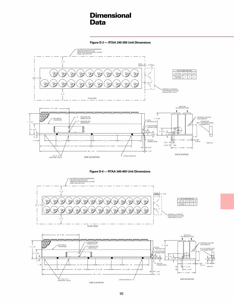
55
DimensionalData
Figure D-3 — RTAA 240-300 Unit Dimensions
Figure D-4 — RTAA 340-400 Unit Dimensions

56
Weights
Table W-1 — WeightsIsolator Location Operating Shipping
Unit Size Units 1 2 3 4 5 6 7 8 9 10 Weight WeightRTAA 70 lbs. 1582 1608 1212 1232 842 856 — — — — 7332 7000
kg 718 729 550 559 382 388 — — — — 3326 3175RTAA 80 lbs. 1587 1613 1218 1237 848 862 — — — — 7365 7049
kg 720 732 552 561 385 391 — — — — 3341 3197RTAA 90 lbs. 1639 1596 1271 1237 903 879 — — — — 7525 7234
kg 743 724 577 561 410 399 — — — — 3413 3281RTAA 100 lbs. 1640 1668 1281 1303 922 937 — — — — 7751 7483
kg 744 757 581 591 418 425 — — — — 3516 3394RTAA 110 lbs. 1933 1885 1480 1443 1027 1001 — — — — 8769 8326
kg 877 855 671 655 466 454 — — — — 3978 3777RTAA 125 lbs. 1871 1902 1445 1469 1019 1036 — — — — 8742 8360
kg 849 863 655 666 462 470 — — — — 3965 3792RTAA 130 lbs. 1982 1729 1657 1446 1332 1163 1007 879 — — 11195 10792
kg 899 784 752 656 604 528 457 399 — — 5078 4895RTAA 140 lbs. 1989 1737 1664 1453 1339 1169 1013 885 — — 11249 10867
kg 902 788 755 659 607 530 459 401 — — 5103 4929RTAA 155 lbs. 2109 1748 1797 1489 1484 1230 1172 971 — — 12000 11392
kg 957 793 815 675 673 558 532 440 — — 5443 5167RTAA 170 lbs. 2143 1735 1843 1492 1543 1249 1242 1006 — — 12253 11675
kg 972 787 836 677 700 567 563 456 — — 5558 5296RTAA 185 lbs. 2144 1824 1852 1575 1560 1327 1268 1078 — — 12628 12085
kg 973 827 840 714 708 602 575 489 — — 5728 5482RTAA 200 lbs. 2117 1844 1842 1606 1568 1368 1293 1130 — — 12768 12261
kg 960 836 836 728 711 621 587 513 — — 5792 5562RTAA 215 lbs. 2162 1997 1957 1808 1752 1618 1546 1428 — — 14268 13472
kg 981 906 888 820 795 734 701 648 — — 6472 6111RTAA 240 lbs. 2038 2011 1995 1969 1953 1928 1911 1886 1869 1845 19405 18147
kg 924 912 905 893 886 875 867 855 848 837 8802 8231RTAA 270 lbs. 2163 2042 2113 1995 2063 1947 2013 1900 1963 1853 20052 18858
kg 981 926 958 905 936 883 913 862 890 841 9096 8554RTAA 300 lbs. 2148 2121 2099 2072 2049 2023 2000 1975 1951 1926 20364 19240
kg 974 962 952 940 929 918 907 896 885 874 9237 8727RTAA 340 lbs. 2789 2604 2611 2438 2433 2272 2248 2099 2077 1939 23510 22475
kg 1265 1181 1184 1106 1104 1031 1020 952 942 880 10664 10195RTAA 370 lbs. 2913 2624 2720 2449 2526 2275 2325 2094 2139 1926 23991 23026
kg 1321 1190 1234 1111 1146 1032 1055 950 970 874 10882 10445RTAA 400 lbs. 2936 2741 2737 2555 2537 2369 2330 2175 2139 1997 24516 23621
kg 1332 1243 1242 1159 1151 1075 1057 987 970 906 11120 10714Notes:1. Operating weight includes refrigerant and water.2. Shipping weight includes refrigerant.3. 70-125 ton units have 6 isolator locations. 130-215 ton units have 8 isolator locations. 240-400 ton units have 10 isolator locations.4. All weights ± 3%.

57
Options
Low Temperature BrineThe unit controls can be factory set tohandle low temperature brineapplications (0 F to 39 F).
Ice MakingThe unit controls can be factory set tohandle ice making for thermal storageapplications.
Building Automation SystemCommunication InterfacePermits either bi-directionalcommunication to the Trane IntegratedComfort™ system or permits remotechilled water setpoint and demandlimiting by accepting a 4-20 mA or 2-10Vdc analog signal.
Remote DisplayIn addition to controlling chilleroperation from a location within thebuilding, the remote display shallprovide the capability to monitor unitalarms and diagnostics. Only onetwisted pair is required between thechiller and the remote display (requiresCommunication Package on 130-400ton only).
Remote EvaporatorThe remote evaporator option isavailable as a standard option on RTAA70-200 and a design special on RTAA240-400.
This option provides an easily installed,pre-engineered method of installing theevaporator remotely indoors.The remote evaporator is skid-mounted and is shipped separatelyfrom the outdoor (condensing) unit.Refrigerant accessories, includingelectronic expansion valve, moistureindicating sightglass and removablecore filter drier, are shipped with theevaporator skid. All refrigerantconnections are routed to one end ofthe evaporator skid for easyconnection. All electrical wiring isfactory installed and routed to aterminal box (entering and leavingwater temperature sensor, evaporatorrefrigerant temperature sensor andelectronic expansion valve controlwiring). Suction refrigeranttemperature sensors (two) must befield installed in the field suction linepiping next to the evaporatorconnections.
Domestic Hot Water HeaterThis heat recovery option will recoversome of the heat normally rejected tothe atmosphere to be used to heatsmall quantities of high temperaturewater up to 140 F (130-215 tons only).
Chilled Water ResetThis option provides the control logicand field installed sensors for eitherload based (return water temperature)or temperature based (ambient orzone) reset of leaving chilled watertemperature (requires CommunicationPackage).
Architectural Louvered PanelsLouvered panels cover the completecondensing coil and the service areabeneath the coils.
Coil ProtectionLouvered panels which protect thecondenser coils only.
Access ProtectionA coated wire mesh which coversaccess area underneath the condensercoils.
Control Power TransformerThis option eliminates the need to runseparate 115 volt control power to theunit. A control power transformer isfactory installed and wired. A separate115 volt power source is required for60 Hz heat tape.
Low Ambient OptionThe low ambient option consists ofspecial control logic and fans to permitlow temperature operation.
Low Ambient LockoutA factory installed ambient sensor andcontrol logic can prevent starting belowthe recommended temperature.
Non-Fused Power Disconnect SwitchA non-fused disconnect switch with athrough the door handle is provided todisconnect main power.
Circuit BreakerA standard interrupting molded casecapacity circuit breaker (UL approved)is available. The circuit breaker can alsobe used to disconnect the chiller frommain power with a through the doorhandle and comes pre-wired from thefactory with terminal block powerconnections.
Neoprene IsolatorsIsolators provide isolation betweenchiller and structure to help eliminatefrequency transmission. Neopreneisolators are more effective andrecommended over spring isolators.
Spring IsolatorsSpring isolators help isolate the chillerfrom the building structure.
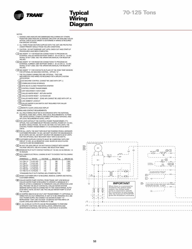
58
TypicalWiringDiagram
70-125 Tons
NOTES:
1. DASHED LINES INDICATE RECOMMENDED FIELD WIRING BY OTHERS.PHANTOM LINES INDICATE ALTERNATE CIRCUITRY OR AVAILABLE SALESOPTION. CHECK SALES ORDER TO DETERMINE IF WIRING IS REQUIREDFOR SPECIFIC OPTIONS.
2. ALL THREE PHASE MOTORS SUPPLIED WITH THE UNIT ARE PROTECTEDUNDER PRIMARY SINGLE PHASE FAILURE CONDITIONS.
3. CAUTION - DO NOT ENERGIZE UNIT UNTIL CHECK OUT AND START-UPPROCEDURES HAVE BEEN COMPLETED.
4 SEE INSERT “A” FOR RESISTOR CONNECTIONS TO PROGRAM ANEXTERNAL CHILLED WATER SETPOINT WHEN 4 - 20 mA OR A 2 - 10 VDCSIGNAL IS NOT USED. SEE THE OPERATORS MANUAL FOR RESISTORVALUES.
5 SEE INSERT “B” FOR RESISTOR CONNECTIONS TO PROGRAM ANEXTERNAL CURRENT LIMIT SETPOINT WHEN 4 - 20 mA OR A 2 - 10 VDCSIGNAL IS NOT USED. SEE THE OPERATORS MANUAL FOR RESISTORVALUES.
6 SEE INSERT “C” FOR CONTACTS (IN PLACE OF THE ZONE TEMP. SENSOR)FOR OPTIONAL ICE MACHINE CONTROL - OPTION “A”.
7. THE FOLLOWING CAPABILITIES ARE OPTIONAL - THEY AREIMPLEMENTED AND WIRED AS REQUIRED FOR A SPECIFIC SYSTEMAPPLICATION.
A ICE-MACHINE CONTROL (CANNOT BE USED WITH OPT. L)
B COMMUNICATIONS INTERFACE
D WYE-DELTA CLOSED TRANSITION STARTER
E CONTROL POWER TRANSFORMER.
H UNIT DISCONNECT, NON-FUSED
J CHILLED WATER RESET - RETURN WATER
K CHILLED WATER RESET - OUTDOOR AIR
L CHILLED WATER RESET - ZONE AIR (CANNOT BE USED WITH OPT. A)
O LOW AMBIENT LOCKOUT
S CHILLED WATER FLOW SWITCH (NOT REQUIRED FOR CHILLERPROTECTION)
T REMOTE CLEAR LANGUAGE DISPLAY
WIRING AND CONTACT REQUIREMENTS:
20. ALL FIELD WIRING MUST BE IN ACCORDANCE WITH THE NATIONALELECRICAL CODE (NEC), STATE, AND LOCAL REQUIREMENTS. OUTSIDETHE UNITED STATES, OTHER COUNTRIES APPLICABLE NATIONAL AND/OR LOCAL REQUIREMENTS SHALL APPLY.
21 FOR UNITS WITHOUT THE CONTROL POWER TRANSFORMER (1T1)OPTION, THE CUSTOMER MUST PROVIDE CONTROL POWER OF 115 VAC,60 HERTZ, SINGLE PHASE, 750 VA ON 130 THRU 215 TON UNITS. THECONTROL POWER TRANSFORMER (1T1) IS STANDARD ON 50 HERTZUNITS.
22 FOR ALL UNITS, THE HEAT TAPE MUST BE POWERED FROM A SEPARATECUSTOMER PROVIDED 115 VAC, 420 WATT SOURCE FOR 200/230/420/57560 HZ UNITS: 220 VAC, 420 WATT SOURCE FOR 346/380/415 50 HZ UNITS.FOR THE OPTIONAL HEAT RECOVERY HEAT TAPE IS 420 WATTS.
23 CUSTOMER SUPPLIED CONTACTS MUST BE COMPATIBLE WITH DRYCIRCUIT 12 VDC, 45 mA RESISTIVE LOAD. SILVER OR GOLD PLATEDCONTACTS ARE RECOMMENDED.
24 30 VOLT OR LESS CIRCUIT. DO NOT RUN IN CONDUIT WITH HIGHERVOLTAGE CIRCUITS. USE #14-18 AWG. SEE SELECTION TABLE.
25 MINIMUM PILOT DUTY CONTACT RATING AT 115 VAC; 5.9 VA INRUSH, 1.3VA SEALED.
26 FIELD WIRED ELECTRICAL LOADING IS NOT TO EXCEED THE FOLLOWINGRATINGS:
TERMINALS DEVICE VOLTAGE SEALED VA INRUSH VA
1U1-TB4-1,2 1U1K1,NO 115 180 1150*1U1-TB4-3 1U1K1,NC 115 180 1150*1U1-TB4-5,4 1U1K2,NO 115 180 1150*1U1-TB4-6,7 1U1K3,NC 115 180 1150*1U1-TB4-8,9 1U1K2,NO 115 250 1150*1U1-TB4-10,11 1U1K3,NC 115 180 1150*
*STANDARD PILOT DUTY RATING (35% POWER FACTOR).
27 WHEN CUSTOMER INPUT IS REQUIRED, REMOVE JUMPER AND INSTALLCUSTOMER WIRING.
28 CHILLED WATER PUMP CONTROL FROM TRANE UNIT UCM MODULECHILLED WATER PUMP IS REQUIRED TO OPERATE A MINIMUM OF 1MINUTE AFTER A COMMAND TO TERMINATE CHILLER OPERATION (UCMWILL PROVIDE THE DELAY CONTACTS). CHILLED WATER SYSTEMDEMAND SWITCH (5S2) IS CONNECTED TO THE UCM EXTERNAL AUTO/STOP INPUT. NOTE: DO NOT USE THE CHILLED WATER PUMP TO STOPTHE CHILLER.
29 AS SHIPPED 380/415 50 HZ VOLT UNIT TRANSFORMER 1T1-(OPTIONAL) ISWIRED FOR 415 VOLT OPERATION. IF UNIT IS TO BE OPERATED ON A 380VOLT POWER SUPPLY, RE-CONNECT AS SHOWN IN INSET “D”.REPROGRAM “UNIT LINE VOLTAGE” IN SERVICE SETTING MENU OFCLEAR LANGUAGE DISPLAY FROM 415 TO 380.
30 K1, K2, K3 RELAY OUTPUTS CAN BE PROGRAMMED TO PERFORMALTERNATE FUNCTIONS. SEE INSTALLATION, OPERATION ANDMAINTENANCE MANUAL FOR DETAILS. FUNCTION #1 IS SHOWN.

59
TypicalWiringDiagram
70-125 Tons

60
TypicalWiringDiagram
130-215 Tons
NOTES:
1. DASHED LINES INDICATE RECOMMENDED FIELD WIRING BY OTHERS. PHANTOM LINESINDICATE ALTERNATE CIRCUITRY OR AVAILABLE SALES OPTION. CHECK SALES ORDERTO DETERMINE IF WIRING IS REQUIRED FOR SPECIFIC OPTIONS.
2. ALL THREE PHASE MOTORS SUPPLIED WITH THE UNIT ARE PROTECTED UNDERPRIMARY SINGLE PHASE FAILURE CONDITIONS.
3. CAUTION - DO NOT ENERGIZE UNIT UNTIL CHECK OUT AND START-UP PROCEDURESHAVE BEEN COMPLETED.
4 SEE INSERT “A” FOR RESISTOR CONNECTIONS TO PROGRAM AN EXTERNAL CHILLEDWATER SETPOINT WHEN 4 - 20 mA OR A 2 - 10 VDC SIGNAL IS NOT USED. SEE THEOPERATORS MANUAL FOR RESISTOR VALUES.
5 SEE INSERT “B” FOR RESISTOR CONNECTIONS TO PROGRAM AN EXTERNAL CURRENTLIMIT SETPOINT WHEN 4 - 20 mA OR A 2 - 10 VDC SIGNAL IS NOT USED. SEE THEOPERATORS MANUAL FOR RESISTOR VALUES.
6 SEE INSERT “C” FOR CONTACTS (IN PLACE OF THE ZONE TEMP. SENSOR) FOROPTIONAL ICE MACHINE CONTROL - OPTION “A”.
7. THE FOLLOWING CAPABILITIES ARE OPTIONAL - THEY ARE IMPLEMENTED AND WIREDAS REQUIRED FOR A SPECIFIC SYSTEM APPLICATION.
A ICE-MACHINE CONTROL (CANNOT BE USED WITH OPT. L)
B COMMUNICATIONS INTERFACE
D WYE-DELTA CLOSED TRANSITION STARTER
E CONTROL POWER TRANSFORMER.
H UNIT DISCONNECT, NON-FUSED
J CHILLED WATER RESET - RETURN WATER
K CHILLED WATER RESET - OUTDOOR AIR
L CHILLED WATER RESET - ZONE AIR (CANNOT BE USED WITH OPT. A)
O LOW AMBIENT LOCKOUT
Q DELUXE CHILLER MODULE (1U1) INCLUDES:
• REMOTE ALARM/RUNNING/MAX CAPACITY CONTACTS
• DISPLAY OF % VOLTS
• DISPLAY OF STARTS AND HOURS BY COMPRESSOR
• UNDER/OVER VOLTAGE PROTECTION
S CHILLED WATER FLOW SWITCH (NOT REQUIRED FOR CHILLERPROTECTION)
WIRING AND CONTACT REQUIREMENTS:
20. ALL FIELD WIRING MUST BE IN ACCORDANCE WITH THE NATIONAL ELECRICAL CODE(NEC), STATE, AND LOCAL REQUIREMENTS. OUTSIDE THE UNITED STATES, OTHERCOUNTRIES APPLICABLE NATIONAL AND/OR LOCAL REQUIREMENTS SHALL APPLY.
21 FOR CANADIAN INSTALLATION (CSA) ONLY, LOCAL INSPECTION AUTHORITIES MAYREQUIRE SINGLE POWER SOURCE DISCONNECTING MEANS.
22 FOR UNITS WITHOUT THE CONTROL POWER TRANSFORMER (1T1) OPTION, THECUSTOMER MUST PROVIDE CONTROL POWER OF 115 VAC, 60 HERTZ, SINGLE PHASE,750 VA ON 130 THRU 215 TON UNITS. THE CONTROL POWER TRANSFORMER (1T1) ISSTANDARD ON 50 HERTZ UNITS.
23 FOR ALL UNITS, THE HEAT TAPE MUST BE POWERED FROM A SEPARATE CUSTOMERPROVIDED 115 VAC, 420 WATT SOURCE FOR 200/230/420/575 60 HZ UNITS: 220 VAC, 420WATT SOURCE FOR 346/380/415 50 HZ UNITS. FOR THE OPTIONAL HEAT RECOVERYHEAT TAPE IS 420 WATTS.
24 CUSTOMER SUPPLIED CONTACTS MUST BE COMPATIBLE WITHDRY CIRCUIT 12 VDC, 45 mA RESISTIVE LOAD. SILVER OR GOLDPLATED CONTACTS ARE RECOMMENDED.
25 30 VOLT OR LESS CIRCUIT. DO NOT RUN IN CONDUIT WITHHIGHER VOLTAGE CIRCUITS. USE #14-18 AWG. SEE SELECTIONTABLE.
26 MINIMUM CONTACT RATING AT 115 VAC; 6.9 VA INRUSH, 1.3 VASEALED.
27 FIELD WIRED ELECTRICAL LOADING IS NOT TO EXCEED THEFOLLOWING RATINGS:TERMINALS DEVICE VOLTAGE SEALED VA INRUSH VA1U1-TB4-2,1 1U1K1,NO 115 115 1150*1U1-TB4-2,3 1U1K1,NC 115 115 1150*1U1-TB4-5,4 1U1K2,NO 115 115 1150*1U1-TB4-5,6 1U1K2,NC 115 115 1150*
*STANDARD PILOT DUTY RATING (35% POWER FACTOR).
28 WHEN CUSTOMER INPUT IS REQUIRED, REMOVE JUMPER ANDINSTALL CUSTOMER WIRING.
29 AS SHIPPED 200/230 60 HZ AND 380/415 50 HZ VOLT UNITTRANSFORMER 1T1-(OPTIONAL) IS WIRED FOR 200 AND 415VOLT OPERATION RESPECTIVELY. IF UNIT IS TO BE OPERATEDON A 230 OR 380 VOLT POWER SUPPLY, RE-CONNECT ASSHOWN IN INSET “D”, IF THE CHILLER MODULE (1U1) UPGRADE(OPTION Q) IS USED, CHANGE UCM FACTORY DISPLAY MENUITEM 45 FROM 200V OR 415V TO 230V OR 380V RESPECTIVELY.
30 REQUIRED WIRING FOR BASIC UNIT OPERATION. ALL OTHERWIRING IS EITHER FOR OPTIONS OR AT THE CUSTOMERSDISCRETION. NOTE: DO NOT USE THE CHILLED WATER PUMPTO STOP THE CHILLER.
31 346V, 380/415FV 50 HZ; 380V, 460V, 575V 60 HZ UNITS REQUIREMAIN POWER CONNECTION ONLY TO 1TB1, 200/230V 60 HZUNITS REQUIRE MAIN POWER CONNECTIONS TO BOTH 1TB1(CKT #1) AND 1TB2 (CKT #2). AN OPTIONAL SINGLE POINTELECTRICAL POWER CONNECTION IS AVAILABLE. POWERWIRING ENTERS LOWER RIGHT HAND SIDE OF CONTROLPANEL.
32 ALL CUSTOMER CONTROL CIRCUIT WIRING MUST HAVE AMINIMUM RATING OF 150 VOLTS.
33 FOR FIELD CONNECTION, CUT, STRIP, AND WIRE NUT EXISTINGWIRE LOOP TO FIELD WIRING.
34 THE (3) RELAY OUTPUTS CAN BE PROGRAMMED TO PERFORMALTERNATE FUNCTIONS. SEE RTAA-IOM-3 FOR DETAILS.FUNCTION #1IS SHOWN.

61
TypicalWiringDiagram
130-215 Tons

62
TypicalWiringDiagram
240-400 Tons
NOTES:
1. DASHED LINES INDICATE RECOMMENDED FIELD WIRING BY OTHERS.PHANTOM LINES INDICATE ALTERNATE CIRCUITRY OR AVAILABLE SALESOPTION. CHECK SALES ORDER TO DETERMINE IF WIRING IS REQUIREDFOR SPECIFIC OPTIONS.
2. ALL THREE PHASE MOTORS SUPPLIED WITH THE UNIT ARE PROTECTEDUNDER PRIMARY SINGLE PHASE FAILURE CONDITIONS.
3. CAUTION - DO NOT ENERGIZE UNIT UNTIL CHECK OUT AND START-UPPROCEDURES HAVE BEEN COMPLETED.
4 SEE INSERT “A” FOR RESISTOR CONNECTIONS TO PROGRAM ANEXTERNAL CHILLED WATER SETPOINT WHEN 4 - 20 mA OR A 2 - 10 VDCSIGNAL IS NOT USED. SEE THE OPERATORS MANUAL FOR RESISTORVALUES.
5 SEE INSERT “B” FOR RESISTOR CONNECTIONS TO PROGRAM ANEXTERNAL CURRENT LIMIT SETPOINT WHEN 4 - 20 mA OR A 2 - 10 VDCSIGNAL IS NOT USED. SEE THE OPERATORS MANUAL FOR RESISTORVALUES.
6 SEE INSERT “C” FOR CONTACTS (IN PLACE OF THE ZONE TEMP. SENSOR)FOR OPTIONAL ICE MACHINE CONTROL - OPTION “A”.
7. THE FOLLOWING CAPABILITIES ARE OPTIONAL - THEY AREIMPLEMENTED AND WIRED AS REQUIRED FOR A SPECIFIC SYSTEMAPPLICATION.
A ICE-MACHINE CONTROL (CANNOT BE USED WITH OPT. L)
B COMMUNICATIONS INTERFACE
D WYE-DELTA CLOSED TRANSITION STARTER
E CONTROL POWER TRANSFORMER.
H UNIT DISCONNECT, NON-FUSED
J CHILLED WATER RESET - RETURN WATER
K CHILLED WATER RESET - OUTDOOR AIR
L CHILLED WATER RESET - ZONE AIR (CANNOT BE USED WITH OPT. A)
O LOW AMBIENT LOCKOUT
Q DELUXE CHILLER MODULE (1U1) INCLUDES:
• REMOTE ALARM/RUNNING/MAX CAPACITY CONTACTS
• DISPLAY OF % VOLTS
• DISPLAY OF STARTS AND HOURS BY COMPRESSOR
• UNDER/OVER VOLTAGE PROTECTION
S CHILLED WATER FLOW SWITCH (NOT REQUIRED FOR CHILLERPROTECTION)
WIRING AND CONTACT REQUIREMENTS:
20. ALL FIELD WIRING MUST BE IN ACCORDANCE WITH THE NATIONALELECRICAL CODE (NEC), STATE, AND LOCAL REQUIREMENTS. OUTSIDETHE UNITED STATES, OTHER COUNTRIES APPLICABLE NATIONAL AND/OR LOCAL REQUIREMENTS SHALL APPLY.
21 FOR CANADIAN INSTALLATION (CSA) ONLY, LOCAL INSPECTIONAUTHORITIES MAY REQUIRE SINGLE POWER SOURCE DISCONNECTINGMEANS.
22 FOR UNITS WITHOUT THE CONTROL POWER TRANSFORMER (1T1)OPTION, THE CUSTOMER MUST PROVIDE CONTROL POWER OF 115 VAC,60 HERTZ, SINGLE PHASE, 750 VA ON 130 THRU 215 TON UNITS. THECONTROL POWER TRANSFORMER (1T1) IS STANDARD ON 50 HERTZUNITS.
23 FOR ALL UNITS, THE HEAT TAPE MUST BE POWERED FROM A SEPARATECUSTOMER PROVIDED 115 VAC, 420 WATT SOURCE FOR 200/230/420/57560 HZ UNITS: 220 VAC, 420 WATT SOURCE FOR 346/380/415 50 HZ UNITS.FOR THE OPTIONAL HEAT RECOVERY HEAT TAPE IS 420 WATTS.
24 CUSTOMER SUPPLIED CONTACTS MUST BE COMPATIBLE WITH DRYCIRCUIT 12 VDC, 45 mA RESISTIVE LOAD. SILVER OR GOLD PLATEDCONTACTS ARE RECOMMENDED.
25 30 VOLT OR LESS CIRCUIT. DO NOT RUN IN CONDUIT WITH HIGHERVOLTAGE CIRCUITS. USE #14-18 AWG. SEE SELECTION TABLE.
26 MINIMUM CONTACT RATING AT 115 VAC; 6.9 VA INRUSH, 1.3 VA SEALED.
27 FIELD WIRED ELECTRICAL LOADING IS NOT TO EXCEED THE FOLLOWINGRATINGS:
TERMINALS DEVICE VOLTAGE SEALED VA INRUSH VA
1U1-TB4-2,1 1U1K1,NO 115 115 1150*
1U1-TB4-2,3 1U1K1,NC 115 115 1150*
1U1-TB4-5,4 1U1K2,NO 115 115 1150*
1U1-TB4-5,6 1U1K2,NC 115 115 1150*
*STANDARD PILOT DUTY RATING (35% POWER FACTOR).
28 WHEN CUSTOMER INPUT IS REQUIRED, REMOVE JUMPER AND INSTALLCUSTOMER WIRING.
29 AS SHIPPED, 380/415 50 HZ VOLT UNIT TRANSFORMER 1T1 IS WIRED FOR415 VOLT OPERATION. IF UNIT IS TO BE OPERATED ON A 380 VOLTPOWER SUPPLY, RE-CONNECT AS SHOWN IN INSET “D” IF THE CHILLERMODULE (1U1) UPGRADE (OPTION Q) IS USED, CHANGE UCM FACTORYDISPLAY MENU ITEM 45 FROM 415V TO 380V.
30 REQUIRED WIRING FOR BASIC UNIT OPERATION. ALL OTHER WIRING ISEITHER FOR OPTIONS OR AT THE CUSTOMERS DISCRETION.NOTE: DO NOT USE THE CHILLED WATER PUMP TO STOP THE CHILLER.
31 ALL CUSTOMER CONTROL CIRCUIT WIRING MUST HAVE A MINIMUMRATING OF 150 VOLTS.
32 FOR FIELD CONNECTION, CUT, STRIP, AND WIRE NUT EXISTING WIRELOOP TO FIELD WIRING.
34 THE (3) RELAY OUTPUTS CAN BE PROGRAMMED TO PERFORMALTERNATE FUNCTIONS. SEE RTAA-IOM-3 FOR DETAILS. FUNCTION #1IS SHOWN.
35 AN OPTIONAL SINGLE POINT ELECTRICAL POWER CONNECTION ISAVAILABLE.

63
TypicalWiringDiagram
240-400 Tons

64
FeaturesSummary
Reliability
• Proven Trane helical rotary screwcompressor design for longer life andgreater dependability.
• Fewer moving parts means less partsto fail. Typical reciprocatingcompressors have 4 times as manytotal parts and 15 times as many criticalparts.
• Adaptive Control™ protects the chillerwhen any of the system variablesapproaches a limit condition that maydamage the unit or cause a shutdown.The Unit Control Module takescorrective action to keep the unitrunning.
• Dual circuit design increases overallsystem reliability.
• Unlike reciprocating designs, thiscompressor can handle liquid slugging.
• Suction gas cooling allows the motor tooperate at lower temperatures forlonger life.
Trane RTAA Air-CooledSeries R® ChillerDesigned To Perform, Built To Last
Performance
• Superior full load efficiency (EER 10.0).• Excellent part load performance is
achieved without resorting tomanifolded multiple reciprocatingcompressors.
• Use of an electronic expansion valvesignificantly improves part loadperformance by minimizing superheatin the evaporator and allowing thechiller to run at reduced condensingtemperatures.
• Unique compressor sequencingequalizes not only starts, but operatinghours as well.
Trouble-Free Operation and Start-Up
• Adaptive Control™ microprocessorkeeps the Series R chiller on-line whenothers would shut down.
• Fewer nuisance trips means lessexpense from unnecessary servicecalls.
• Factory installed and tested optionskeep start-up time and expensesminimized.
• Easy interface capability with the TraneIntegrated Comfort™ system via asingle twisted pair of wires.
• Optional remote display panelsimplifies chiller monitoring/ control.
• Packed stock availability for yourordering convenience.

65
MechanicalSpecifications
GeneralUnits are leak and pressure tested at450 psig high side, 300 psig low side,then evacuated and charged. Packagedunits ship with a full operating chargeof oil and refrigerant.
Unit panels, structural elements andcontrol boxes are constructed of12-gauge galvanized steel andmounted on a welded structural steelbase. Unit panels and control boxes arefinished with a baked on powder paint,and the structural base with an air drypaint. All paint meets the requirementfor outdoor equipment of theU.S. Navy and other federalgovernment agencies.
EvaporatorThe evaporator is a tube-in-shell heatexchanger design with internally finnedcopper tubes roller expanded into thetube sheet. The evaporator is designed,tested and stamped in accordance withASME for a refrigerant side workingpressure of 300 psig. The evaporator isdesigned for a water side workingpressure of 215 psig. Waterconnections are grooved pipe. Theevaporator has one water pass with aseries of internal baffles. Each shellincludes a vent, a drain and fittings fortemperature control sensors and isinsulated with 3/4-inch Armaflex II orequal insulation (K=0.26). Heat tapewith thermostat is provided to protectthe evaporator from freezing atambient temperatures down to -20 F.
Condenser and FansAir-cooled condenser coils havealuminum fins mechanically bonded tointernally finned seamless coppertubing. The condenser coil has anintegral subcooling circuit and alsoprovides oil cooling for the compressorbearing and injection oil. Condensersare factory proof and leak tested at506 psig.
Direct-drive vertical dischargecondenser fans are dynamicallybalanced. Three-phase condenser fansmotors with permanently lubricatedball bearing and internal thermaloverload protection are provided.Standard 70-215 ton units will start andoperate down to 25 F ambient.Standard 130-215 ton units will startand operate down to 15 F ambient.Standard 240-400 ton units will startand operate down to 0 F ambient.
Compressor and Lube Oil SystemThe rotary screw compressor is semi-hermetic, direct drive, 3600 rpm, withcapacity control slide valve, rollingelement bearings, differentialrefrigerant pressure oil pump and oilheater. The motor is a suction gascooled, hermetically sealed, two-polesquirrel cage induction motor.
Oil separator and filtration devices areprovided separate from thecompressor. Check valves in thecompressor discharge and lube oilsystem and a solenoid valve in the lubesystem are provided.
Remote EvaporatorThe evaporator is a tube-in-shell heatexchanger, designed with internally-finned copper tubes that are rolledexpanded into the tube sheet. Theevaporator is designed, tested andstamped for a refrigerant side workingpressure of 300 psig, in accordancewith ASME. The evaporator isdesigned for a water side workingpressure of 215 psig. Waterconnections are victaulic. Theevaporator has one water pass, with aseries of internal baffles.
Each shell includes a vent and drainconnection, as well as factory-mountedentering and leaving watertemperature control sensors andevaporator refrigerant temperaturesensors. The evaporator is insulatedwith 3/4-inch Armaflex II or equalinsulation (K=0.26).
The evaporator is skid-mounted and isshipped separately from the outdoor(condensing) unit. Refrigerantaccessories, including electronicexpansion valve, moisture indicatingsightglass and removable core filterdrier, are shipped with the evaporatorskid. All refrigerant connections arerouted to one end of evaporator skidfor easy connection. All electrical wiringis factory installed and routed to aterminal box (entering and leavingwater temperature sensor, evaporatorrefrigerant temperature sensor andelectronic expansion valve controlwiring). Suction refrigeranttemperature sensors (two) must befield installed in the field suction linepiping next to the evaporatorconnections.

66
Refrigeration CircuitsEach unit has two refrigerant circuits,with one or two rotary screwcompressors per circuit. Eachrefrigerant circuit includes acompressor suction and dischargeservice valve, liquid line shutoff valve,removable core filter drier, liquid linesight glass with moisture indicator,charging port and an electronicexpansion valve. Fully modulatingcompressors and electronic expansionvalves provide variable capacitymodulation over the entire operatingrange.
Unit ControlsAll unit controls are housed in aweathertight enclosure with removableplates to allow for customer connectionof power wiring and remote interlocks.All controls, including sensors, arefactory mounted and tested prior toshipment. All cataloged units areUL listed.
Microcomputer controls provide allcontrol functions including start-up andshut down, leaving chilled watertemperature control, compressor andelectronic expansion valve modulation,fan sequencing, antirecycle logic,automatic lead/lag compressor startingand load limiting.
The unit control module, utilizingAdaptive Control™ microprocessor,automatically takes action to avoid unitshutdown due to abnormal operatingconditions associated with lowrefrigerant temperature, highcondensing temperature and motorcurrent overload. Should the abnormaloperating condition continue until aprotective limit is violated, the unit willbe shut down.
Unit protective functions include loss ofchilled water flow, evaporator freezing,loss of refrigerant, low refrigerantpressure, high refrigerant pressure,reverse rotation, compressor startingand running over current, phase loss,phase imbalance, phase reversal, andloss of oil flow.
A menu driven digital display indicatesover 20 operating data points includingchilled water setpoint, current limitsetpoint, leaving chilled watertemperature, evaporator andcondenser refrigerant pressures andtemperatures. Over 60 diagnosticchecks are made and displayed when aproblem is detected. The digital displaycan be read and advanced on the unitwithout opening any control paneldoors.
Standard power connections includemain three phase power and two 115volt single phase power connectionsfor control power and heat tape.
StartersStarters are housed in a weathertightenclosure with removable cover plateto allow for customer connection ofpower wiring. Across-the-line startersare standard on all 460-575 volt units.Wye Delta closed transition starters(33 percent of LRA inrush) are standardon 70-400 ton 200-230 volt units.An optional Wye Delta closed transitionstarter (33 percent of LRA inrush) isavailable on 70-215 ton 460-575 voltunits. Typically, Trane helical rotarycompressors are up to full speed in onesecond when started across-the-lineand have equivalent inrush with similarsize reciprocating compressor with partwind starters.
MechanicalSpecifications

67
StandardConversionTable

Library Product Literature
Product Section Refrigeration
Product Rotary Liquid Chillers
Model 000
Literature Type Data Sales Catalog
Sequence 2
Date June 1999
File No. PL-RF-RLC-000-DS-2-699
Supersedes RLC-DS-2 895
Ordering No. RLC-DS-2
Worldwide Applied Systems GroupThe Trane Company3600 Pammel Creek RoadLa Crosse, WI 54601-7599www.trane.com
An American Standard Company
Since The Trane Company has a policy of continuousproduct improvement, it reserves the right to changedesign and specification without notice.