RIVER PROTECTION PROJECT-WASTE TREATMENT PLANT FOR … · Revision Riston Revision Reason for...
56
{ RSOOOl 693 Ill I IIIIII IIIIIIIIII Ill II Ill • RIVER PROTECTION PROJECT- WASTE TREATMENT PLANT ENGINEERING SPECIFICATION FOR High Integrity Centrifugal Blowers - Multi-stage Please note that source, special nuclear, and byproduct materials, as defined in the Atomic Energy Act of 1954 (AEA) are regulated at the U. S. Department of Energy (DOE) facilities exclusively by DOE acting pursuant to its AEA authority. DOE asserts that pursuant to AEA, it has sole and exclusive responsibility and authority to regulate source, special nuclear, and byproduct materials at DOE-owned nuclear facilities. Information contained herein on radionuclides is provided for process description purposes only. Content applicable to ALARA? D Yes [SJ No Quality Level ADRNo. Rev Q Specification changes retroactive? D Yes [SJ No D N/A (alpha revision or revision 0) DOE Contract No. DE-AC27-01RV14136 NOTE: Contents of this document are Dangerous Waste Permit affecting. J/4 t.A ,_ 1• II• 0 Vo/.eakt> ~ei rr'u' ~· 111, if, iM~n• H I' i J,MM,JV .,μ = i. , ,/,I.A• ~,ll...,, • I' D~/.({l.A/./t,I ., REV DATE ~l CHECK ,v REVIEW E&NS DPEM/EM SPECIFICATION No. Rev 24590-WTP-3PS-MACS-T0005 0 24590-G04B-F00009 Rev 14 (Revised 7/7/2010) Page i Ref: 24590-WTP-3DP-G04B-00049
Transcript of RIVER PROTECTION PROJECT-WASTE TREATMENT PLANT FOR … · Revision Riston Revision Reason for...
{ RSOOOl693 Ill I IIIIII IIIIIIIIII Ill II Ill
• RIVER PROTECTION PROJECT- WASTE TREATMENT PLANT
ENGINEERING SPECIFICATION
FOR
High Integrity Centrifugal Blowers - Multi-stage
Please note that source, special nuclear, and byproduct materials, as defined in the Atomic Energy Act of 1954 (AEA) are regulated at the U. S. Department of Energy (DOE) facilities exclusively by DOE acting pursuant to its AEA authority. DOE asserts that pursuant to AEA, it has sole and exclusive responsibility and authority to regulate source, special nuclear, and byproduct materials at DOE-owned nuclear facilities. Information contained herein on radionuclides is provided for process description purposes only.
Content applicable to ALARA? D Yes [SJ No Quality Level
ADRNo. Rev Q Specification changes retroactive? D Yes [SJ No
D N/A (alpha revision or revision 0) DOE Contract No. DE-AC27-01RV14136
NOTE: Contents of this document are Dangerous Waste Permit affecting.
J/4 t.A ,_ 1• II•
0 Vo/.eakt> ~ei rr'u' ~· 111, if, iM~n• H I' i J,MM,JV .,µ = i. , ,/,I.A• ~,ll...,, • I' D~/.({l.A/./t,I .,
REV DATE ~l CHECK ,v REVIEW E&NS DPEM/EM
SPECIFICATION No. Rev 24590-WTP-3PS-MACS-T0005 0
24590-G04B-F00009 Rev 14 (Revised 7/7/2010)
Page i Ref: 24590-WTP-3DP-G04B-00049

Revision Riston
Revision Reason for Revision
24590-WTP-3PS-MACS-T000S, Rev 0 High Integrity Centrifugal Blowers - Multi-stage
0 Issued for Purchase. There are no changes in this specification from Revision A to Revision 0.
24590-G04B-F00009 Rev 14 (717/2010) Page ii
Ref: 24590-WTP-3DP-G04B-00049

Notice
Ene
24590-WTP-3PS-MACS-TOOOS, Rev 0 High Integrity Centrifugal Blowers-Multi-stage
AE,A it has sole and exclusive res )Onsibili and authoritv to regulate source. s e-cial nuclear. and by[roduct materials at DOE-owned nuclear facilities. Information contained herein on radlonudides is rovided for process <lescrit riou. • oses oni
24590-G04B-F00019 Rev 4 (2/12/2008) Page iii
Ref: 24590-WTP-3DP-G04B-00049

Contents
2459D-WTP-3PS-MACS-TODDS, Rev 0 High Integrity Centrifugal Blowers-Multi-stage
1 Scope ........................................................................................................................................ 1
1.1 Project Description and Location ......................................................................................................... 1
1.2 Equipment, Material, and Services Required ...................................................................................... 1
1.3 Work by Others ...................................................................................................................................... 1
1.4 Definitions ............................................................................................................................................... 2
1.5 Abbreviations ......................................................................................................................................... 2
1.6 Safety/Quality Classifications ................................................................................................................ 3
2 Applicable Documents .............................................................................................................. 3
2.1 Codes ....................................................................................................................................................... 3
2.2 Industry Standards ................................................................................................................................ 3
2.3 Reference Documents/Drawings ........................................................................................................... 4
3 Design Req uirements .............................................................................................................. 5
3.1 General .................................................................................................................................................... 5
3.2 Basic Function ........................................................................................................................................ 5
3.3 Performance ........................................................................................................................................... 5
3.4 Lifting and Handling Requirements ..................................................................................................... 5
3.5 Sound Ratings ......................................................................................................................................... 5
3.6 Design Conditions ................................................................................................................................... 6
3.7 Environmental Conditions .................................................................................................................... 6
3.8 Mechanical Requirements ..................................................................................................................... 6
3.9 Electrical Requirements ........................................................................................................................ 9
3.10 Low Voltage Induction Motors ........................................................................................................... 11
3.11 Instrumentation and Control Requirements ..................................................................................... 11
3.12 Accessibility and Maintenance ............................................................................................................ 16
3.13 Accessories ............................................................................................................................................ 17
4 Materials .......................................................................................................................................................................... 17
4.1 Construction ......................................................................................................................................... 17
4.2 Electrical ............................................................................................................................................... 18
4.3 Prohibited Materials ............................................................................................................................ 19
5 Fabrication ...................................................................................................................................................................... 19
5.1 Fabrication of Blowers ......................................................................................................................... 19
5.2 Welding ................................................................................................................................................. 19
6 Tests and Inspections ........................................................................................................................ 20
6.1 General .................................................................................................................................................. 20
24590-G04B-F00019 Rev 4 (2/12/2008) Page iv
Ref: 24590-WTP-3DP-G04B-00049
24590-WTP-3PS-MACS-T000S, Rev 0 High Integrity Centrifugal Blowers-Multi-stage
6.2 Environmental :E;quipment Qualification ........................................................................................... 20
6.3 Seismic Equipment Qualification ........................................................................................................ 20
6.4 Personnel Qualifications ...................................................................................................................... 20
6.5 Non-Destructive Examinations ........................................................................................................... 20
6.6 Shop Tests ............................................................................................................................................. 21
6.7 Site Tests ............................................................................................................................................... 21
7 Preparation for Shipment ..................................... ~ ............................................................. 21
7.1 General .................................................................................................................................................. 21
7.2 Cleanliness ............................................................................................................................................ 22
7.3 Painting and Special Protective Coatings ........................................................................................... 22
7.4 Tagging .................................................................................................................................................. 22
7.5 Packaging .............................................................................................................................................. 22
7.6 Documentation ..................................................................................................................................... 22
8 Quality Assurance ............................................................................................................... 22
8.1 QA requirements specific to item(s) or service .................................................................................. 22
8.2 Supplier Deviation .................................................................................. ; ............................................. 23
9 Configuration Management ............................................................................................... 23
10 Documentation and Submittals .......................................................................................... 23
10.1 General .................................................................................................................................................. 23
10.2 Submittals ............................................................................................................................................. 23
Attachment A Noise Requirements for Fans and Blowers ..................................................... A-i
Attachment B High Integrity Centrifugal Blowers-Multi-stage -Customized Coating Specification ....................................................................................................................... B-i
24590-G04B-F00019 Rev 4 (2/12/2008) Pagev
Ref: 24590-WTP-3DP-G04B-00049

1 Scope
1.1 Project Description and Location
24590-WTP-3PS-MACS-T000S, Rev 0 High Integrity Centrifugal Blowers-Multi-stage
The River Protection Project-Waste Treatment Plant (WTP) is a complex of waste treatment facilities where the Department of Energy's (DOE) Hanford site tank waste will be put into stable glass form. The WTP Contractor will design, build, and start up the WTP pretreatment and vitrification facilities for the US Department of Energy's (DOE) Office of River Protection (ORP). The waste treatment facilities will pretreat and immobilize the mixed waste both low-activity waste, (LAW) and high-level waste, (HL W) currently stored in underground storage tanks at the Hanford Site.
The Hanford Site occupies an area of about 560 square miles and is located along the Columbia River, north of the city of Richland, Washington. The WTP Facility will be constructed at the East End of the 200 East Area of the Hanford Site. Benton, Franklin, and Grant counties surround the Hanford Site.
1.2 Equipment, Material, and Services Required
Design, furnish materials, fabricate, test, and package the High Integrity Centrifugal Blowers (hereinafter called Blowers) and accessories in accordance with this specification including:
1.2.1 Blowers, each complete with electric motors, and accessories as specified here and in referenced technical specifications and data sheets attached to the Material Requisition (MR).
1.2.2 Special tools required for installation and maintenance, including accessories for lifting the motors and blowers.
1.2.3 Each blower/motor assembly shall include all components, accessories, and instruments fully assembled, wired, and skid mounted requiring only connection to the Buyer's electrical power, control systems, and ductwork.
1.2.4 Services of an erection and/or startup supervisor, if requested by Buyer.
1.3 Work by Others
1.3.1 Material unloading and storage atjobsite
1.3 .2 Installation labor
1.3 .3 Foundation and anchor bolts
1.3 .4 Ductwork external to the unit
1.3.5 Electric power supply
1.3.6 Wiring external to the blower motor and adjustable speed drive
1.3.7 Field Testing and Inspection
1.3.8 Integrated testing with Adjustable Speed Drive
24590-G04B-F00019 Rev 4 (2/12/2008) Page 1
Ref: 24590-WTP-3DP-G04B-00049

24590-WTP-3PS-MACS-TO00S, Rev 0 High Integrity Centrifugal Blowers-Multi-stage
1.4 Definitions
1.5
Quality Level
Q
Identifies the quality requirements to be applied to WTP Project's Systems, Structures and Components (SSCs), and activities based on safety classification and SSC characteristic. Identified quality levels are Q, and CM. Applicable ASME NQA-1 requirements are shown on the Supplier Quality Assurance Program Requirement data sheet attached to the MR.
A quality level that includes Safety Class (SC), Safety Significant (SS) and Air Permit (AP) affecting SSCs.
Safety Class (SC) An SSC whose preventive or mitigating function is necessary to limit radioactive material exposure to the public.
Safety Significant (SS) An SSC whose preventive or mitigating function is a major contributor to defense-in-depth and/or worker safety.
Seismic Category WTP Project's seismic classifications ofSSC's based on their safety function.
Abbreviations
ABMA
AMCA
ANSI
ASNT
ASME
ASTM
AWS
dBA
HELB
IPS
ISO
LOCA
NEMA
NrPA
OEM
OSHA
QA
RPP-WTP
RTD SCFM
SC
ss
Seismic categories utilized in this specification are Seismic Category I (SC-I) and Seismic Category III (SC-III).
American Bearing Manufacturers Association
Air Movement and Control Association, Inc.
American National Standards Institute
American Society for Nondestructive Testing
American Society of Mechanical Engineers
ASTM International
American Welding Society
A-weighted decibel (unit of sound pressure level)
High Energy Line Break
International Pipe Standard
International Standards Organization
Loss of Cooling Accident
National Electrical Manufacturers Association
National Fire Protection Association
Original Equipment Manufacturer
Occupational Safety & Health Act
Quality Assurance
River Protection Project-Waste Treatment Plant
Resistance Temperature Detector
Standard Cubic Feet per Minute
Safety Class
Safety Significant
Page2 24590-G04B-F00019 Rev 4 (2/12/2008) Ref: 24590-WTP-3DP-G04B-00049

24590-WTP-3PS·MACS·T000S, Rev 0 High Integrity Centrifugal Blowers-Multi-stage
SSC Structure, System, or Component
1.6 Safety/Quality Classifications
The equipment supplied under this specification is safety class (SC) or safety significant (SS) and/or waste permit affecting and provides either a passive safety function or both an active mechanical and electrical safety function. The equipment provided under this specification provides the motive force for the process off-gas treatment systems. Specific safety class, quality level, and seismic category classifications for the individual blowers described in this specification are specified in blower data sheets attached to the PO.
2 Applicable Documents
The following documents form a part of this specification to the extent specified herein. In the event of conflict between the document referenced herein and the contents of this specification, Seller shall notify Buyer and obtain approval for its disposition.
2.1 Codes
2.1.1 ASME B & PVC-1995, Section IX - Qualification Standard for Welding and Brazing
2.1.2 ASME NQA-1-2000, Quality Assurance Program Requirements for Nuclear Facility Applications
2.1.3 AWS D1.1-2000, Structural Welding Code, Steel
2.1.4 A WS D 1.3-98, Structural Welding Code, Sheet Steel
2.1.5 A WS D 1.6-99, Structural Welding Code, Stainless Steel
2.1.6 AWS D9.1-2000, Sheet Metal Welding Code
2.1.7 AWS D14.6-96, Welding of Rotating Elements of Equipment
2.1.8 ASME PTC-10-1997, Performance Test Codes on Compressors and Exhausters
2.1.9 UBC 1997, Uniform Building Code
2.1.10 29 CFR 1910, Occupational Safety and Health Standards
2.1.11 NFPA 70-1999, National Electrical Code
2.2 Industry Standards
2.2.1 ABMA 9-1990, Load Ratings and Fatigue Life for Ball Bearings
2.2.2 ABMA 11-1990, Load Ratings and Fatigue Life for Roller Bearings
2.2.3 AMCA 99-2404-1978, Drive Arrangement for Centrifugal Fans
24590-G04B-F00019 Rev 4 (2/12/2008) Page3
Ref: 24590-\VfP-3DP-G04B-00049

24590·WTP-3PS-MACS-T0005, Rev 0 High Integrity Centrifugal Blowers-Multi-stage
2.2.4 AMCA 99-2406-1983, Designations for Rotation and Discharge of Centrifugal Fans
2.2.5 AMCA 300-2005, Reverberant Room Method of Sound Testing of Fans
2.2.6 AMCA 301-1990, Method for Calculating Fan Sound Ratings From Laboratory Test Data
2.2.7 ASNT-SNT-TC-lA-2001, ANST Recommended Practice
2.2.8 ISO 3744-1995, Acoustics - Determination of Sound Power Levels of Noise Sources Using Sound Pressure - Engineering Method in an Essentially Free Field over a Reflecting Plane
2.2.9 ISO 1940-1:2003, Mechanical Vibration- Balance Quality Requirements For Rotors In A Constant (Rigid) State- Part 1: Specification And Verification Of Balance Tolerances
2.2.10 NEMA MG 1-1998, Motors and Generator
2.2.11 NEMA WC 55, Instrumentation Cables and Thermocouple Wire - ICEA S-82-552
2.2.12 NEMA WC 57, Standard for Control Cables -ICEA S-73-532
2.3 Reference Documents/Drawings
2.3.1 24590-WTP-3PS-FB01-T0001, Engineering Specification for Structural Design Loads for Seismic Category III/IV Equipment and Tanks.
2.3.2 24590-WTP-3PS-GO00-T0001, General Specification for Supplier Quality Assurance Program Requirements.
2.3.3 24590-WTP-3PS-G000-T0014, Engineering Specification for Supplier Design Analysis.
2.3.4 24590-WTP-3PS-JQ06-T0005, Engineering Specification for Environmental Qualification of Control and Electrical Systems and Components
2.3.5 24590-WTP-3PS-JQ06-T0003, Engineering Specification for Seismic Qualification of Seismic I Control and Electrical Systems and Components
2.3.6 24590-WTP-3PS-MUMI-T0002, Engineering Specification for Low Voltage Induction Motors.
2.3. 7 24590-WTP-3PS-SS90-T000 1, Engineering Specification for Seismic Qualifications of Seismic Category I/II Equipment and Tanks.
2.3.8 24590-WTP-3PS-JQ07-T0001, Engineering Specification for Instrumentation for Package Systems (For BN1 use only)
2.3.9 24590-WTP-3PS-EKP0-T0001, Engineering Specification for Instruction for Package Systems (For BNI use.only)
2.3.10 24590-WTP-LIST-CON-08-0001, Restricted Materials List.
2.3.11 24590-WTP-3PS-G000-T0019, Engineering Specification for Acquisition of Commercial Items and Services for use in Safety Applications at WTP
24590-G04B-F00019 Rev 4 (2/12/2008) Page4
Ref: 24590-WTP-3DP-G04B-00049
24590-WTP-3PS-MACS-T000S, Rev 0 High Integrity Centrifugal Blowers-Multi-stage
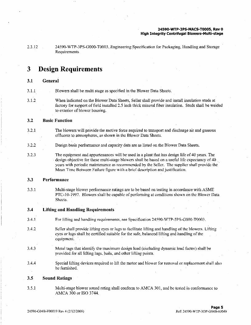
2.3.12 24590-WTP-3PS-G000-T0003, Engineering Specification for Packaging, Handling and Storage Requirements
3 Design Requirements
3.1 General
3.1.1 Blowers shall be multi stage as specified in the Blower Data Sheets.
3 .1.2 When indicated on the Blower Data Sheets, Seller shall provide and install insulation studs at factory for support of field installed 2.5 inch thick mineral fiber insulation. Studs shall be welded to exterior of blower housing.
3.2 Basic Function
3.2.1 The blowers will provide the motive force required to transport and discharge air and gaseous effluents to atmospheres, as shown in the Blower Data Sheets.
3.2.2 Design basis performance and capacity data are as listed on the Blower Data Sheets.
3.2.3 The equipment and appurtenances will be used in a plant that has design life of 40 years. The design objective for these multi-stage blowers shall be based on a useful life expectancy of 40 years with periodic maintenance as recommended by the Seller. The supplier shall provide the Mean Time Between Failure figure with a brief description and justification.
3.3 Performance
3.3 .1 Multi-stage blower performance ratings are to be based on testing in accordance with ASME PTC-10-1997. Blowers shall be capable of performing at conditions shown on the Blower Data Sheets.
3.4 Lifting and Handling Requirements
3.4.1 For lifting and handling requirements, see Specification 24590-WTP-3PS-G000-T0003.
3.4.2 Seller shall provide lifting eyes or lugs to facilitate lifting and handling of the blowers. Lifting eyes or lugs shall be certified suitable for the safe, balanced lifting and handling of the equipment.
3.4.3 Metal tags that identify the maximum design load (excluding dynamic load factor) shall be provided for all lifting lugs, bails, and other lifting points.
3.4.4 Special lifting devices required to lift the motor and blower for removal or replacement shall also be furnished.
3.5 Sound Ratings
3.5.1 Multi-stage blower sound rating shall conform to AMCA 301, and be tested in conformance to k\1CA 300 or ISO 3744.
24590-G04B-F00019 Rev 4 (2/12/2008) Pages
Ref: 24590-WTP-3DP-G04B-00049

24590-WTP-3PS-MACS-TOOOS, Rev 0 High Integrity Centrifugal Blowers-Multi-stage
3.5.2 Sound pressure level shall not exceed 85 dBA at 3-feet. Refer to Attachment A- Noise Requirements for Fans and Blowers. If sound pressure exceeds 85 dBA at 3-feet, Seller shall obtain Buyer permission to proceed in the form of a submittal stating estimated sound power level.
3.6 Design Conditions
3.6.1 Design basis performance and capacity data are as listed on the Blower Data Sheets.
3.6.2 Gas stream properties are shown on Blower Data Sheets. Materials of construction used shall be compatible with the effluent being handled, and specified on the Blower Data Sheets
3.6.3 Seller to provide a corrosion analysis based upon gas stream properties as provided on the Blower Data Sheets and provide an estimated useful life for all components.
3.7 Environmental Conditions
3. 7 .1 The environmental conditions for the plant rooms in which the blowers are located are listed on the Environmental Qualification Data Sheets attached to the Blower Data Sheets .
3. 7 .2 Blowers and motors shall be stored in accordance to requirements in section 7 .1.
3.8 Mechanical Requirements
3.8.1 General
3.8.1.1 Blower housings shall be designed for both positive pressures of greater than 125% of the design operating pressure of the blower and negative pressures as specified on the Blower Data Sheets.
3.8.1.2 Blower inlets and outlets shall include allowances for the full dead weight of any flexible connections connected to the inlet and outlet.
3.8.1.3 Shaft speed shall not exceed 3600 rpm unless approved by Buyer. Tip speed of rotating assembly shall not exceed 530 fps unless approved by Buyer.
3.8.1.4 Blower housings shall be designed to prevent any internally propelled missiles from penetrating the housing.
3.8.1.5 Blower inlet and discharge connections shall be provided with temporary protective cover. These covers will be removed prior to connection to Buyer's piping and/or ductwork.
3.8.1.6 If specified on the Blower Data Sheets, braided stainless steel 316L flexible hoses with stainless steel 316L flanges shall be provided to mate with the blowers' inlet and outlet flanges. Stainless steel connectors shall have flexible core of annular corrugated stainless steel 3 l 6L tubing. Braid for the connectors shall be stainless steel 304. End fittings shall be 150# raised face stainless steel 316L flanges conforming to ANSI dimensions. Connectors shall be shipped loose for field installation.
3.8.1.7 Blower drive arrangement shall be as shown on Blower Data Sheet. Drive arrangement designations shall be per AMCA 99-2404. Designations for rotation and discharge shall be per AMCA 99-2406.
24590-G04B-F00019 Rev 4 (2/12/2008) Page6
Ref: 24590-WTP-3DP-G04B-00049

3.8.2
3.8.2.1
3.8.3
3.8.3.1
3.8.3.2
3.8.3.3
3.8.4
3.8.4.l
3.8.4.2
3.8.4.3
3.8.4.4
3.8.4.5
3.8.4.6
3.8.4.7
3.8.5
3.8.5.1
Access Doors and Inspection Ports
24590-WTP-3PS·MACS-TOOOS, Rev 0 High Integrity Centrifugal Blowers-Multi-stage
Multi-stage blowers may be provided with four - 1 inch NPT plugged inspection ports per impeller in lieu of an access door. The -inspection ports shall be located at 90 degree increments around the circumference of the housing, The bottom inspection port shall be utilized as a drain port and shall be supplied with square headed screwed drain plug.
Balance and Vibration Standards
Soft foot is the condition where the bottoms of the equipment "feet" or "base" are not machined flat in the same plane or parallel with their mating ( or mounting) surface creating a situation where all the "feet" or "base" are not equally supporting the weight of the equipment. Each foot must be checked for soft foot. Any vertical or angular soft foot that exceeds 0.003 inches is excessive and must be corrected.
Multi-stage blowers shall be balanced to Quality Grade 2.5 ofISO 1940-1:2003, Mechanical Vibration-Balance Quality Requirements For Rotors In A Constant (Rigid) State- Part 1: Specification And Verification Of Balance Tolerances with results documented and submitted to Buyer. Additionally, multi-stage blowers shall be required to meet 1 mil displacement at 3600
· rpm, filtered-in.
Multistage blower impellers shall be individually balanced and shall be individually replaceable.
Bearings
Multi-stage blowers shall be supplied with radial type grease-lubricated radial roller bearings with L-10 service life of not less than 100,000 hours, unless noted otherwise on the. data sheets.
Multi-stage blower shall incorporate a grease slinger mounted inboard of the bearing to ensure a constant flow of lubricant to the bearing.
Seller shall provide a "heat slinger" device attached to the blower shaft external to the housing to help in dissipation of heat for bearing protection, as required. The "heat slinger" shall be equipped with safety guards.
For all blowers, it shall be possible to replace the bearings without disconnecting any piping or disassembling of the blower housing.
Seals to prevent loss oflubricant and admission of contaminants shall be provided.
Extended lube lines and fittings as required to permit lubrication during operation shall be provided.
Bearing lubricants shall be suitable for use in radiation levels as specified on the Environmental Qualification data sheet attached to the Equipment data sheet.
Shafts
No contact shall be made between the shaft rotor and the housings, other than through the bearings.
24590-G04B-P00019 Rev 4 (2/12/2008) Page7
Ref: 24590-WTP-3DP-G04B-00049

3.8.5.2
3.8.5.3
3.8.5.4
3.8.6
3.8.6.1
3.8.6.2
3.8.6.3
3.8.7
3.8.7.1
3.8.7.2
3.8.7.3
3.8.8
3.8.9
3.8.9.1
3.8.9.2
3.8.9.3
3.8.9.4
24590-WTP-3PS-MACS-T000S, Rev 0 High Integrity Centrifugal Blowers-Multi-stage
Shafts shall be of the material specified on the Blower Data Sheet and shall be turned, ground and polished, with machined keyways for attaching impeller and drive coupling.
Impeller(s) are to be secured to the blower shaft by locknuts or set screws.
The blower impeller and shaft shall be rated for 110% of the design rpm listed on the Blower Data Sheets.
Shaft Seals
Blowers shall be furnished with shaft seals as specified on the Blower Data Sheet.
Shaft seals shall be fully capable of withstanding the required test pressures before, during, and after blower operation.
As noted on the Blower Data Sheet, no process offgas out leakage at the shaft seals is allowed in systems handling potentially toxic emissions. Use of double mechanical seals and purge gas to assure zero process offgas out leakage is acceptable where needed due to positive internal system pressure.
Safety guards
Blowers shall be provided with bolted drive guards that cover the shaft and bearings. Provisions shall be made for insertion of tachometer and access to lube fittings without removal of drive guards.
Safety guards shall be expanded metal with an angle framework or shall be formed plate types.
The guards shall comply with the requirements of OSHA 29 CFR 1910 Subpart O - Machinery and Machine Guarding.
Drive requirements
The drive types shall be as indicated in the blower data sheets attached to the Material Requisition.
Loadings
Blower assemblies shall be self-supporting, capable of carrying the static loads of the blower components and the stress imposed during shipment, installation, and operation.
Seismic qualification of the blowers shall be in accordance with the methods and procedures described in Specification 24590-WTP-3PS-SS90-T000 1, "Seismic Qualification of Seismic Category I/II Equipment and Tanks", or 24590-WTP-3PS-FB01-T0001, "Structural Design Loads for Seismic Category III/IV Equipment and Tanks".
Any additional structural loading will be indicated on the Blower Data Sheets. In-Structure Response Spectra (ISRS) curves for Seismic Category I/II equipment or items are attached to the blower data sheets.
Seller shall submit to the Buyer seismic compliance documentation for permission to proceed.
24590-G04B-F00019 Rev 4 (2/12/2008) Pages
Ref: 24590-WTP-3DP-G04B-00049

24590-WTP-3PS-MACS-TOOOS, Rev 0 High Integrity Centrifugal Blowers-Multi-stage
3.9 Electrical Requirements
3.9.1 Acceptance of Electrical Equipment
3.9.1.1
3.9.1.1.1
3.9.1.2
3.9.1.2.1
3.9.1.2.2
3.9.1.2.3
• All electrical equipment for facility and equipment wiring, as defined by the National Electrical Code NFP A 70-1999, shall be Approved. Approval will be in accordance with Article 90-4, "Enforcements", Article 90-7, "Examination of Equipment for Safety," and Article 110-3, "Examination, Identification, Installation, and Use of Equipment."
• Approved means "Acceptable to the Authority Having Jurisdiction" (AHJ), as defined in Article 100 ofNFPA 70-1999. Only the WTP Electrical AHJ can provide the approval.
• "Equipment" is defin~d by the NFPA 70 as, "A general term including material, fittings, devices, appliances, fixtures, apparatus, and the like used as a part of, or in connection with an electrical installation". As used here, the entire mechanical assembly is not considered an electrical installation, only the electrical and/or electronic components, and the interconnecting wiring.
• Listing and labeling by an OSHA Recognized NRTL is the primary means (Method 1 below) of obtaining WTP AHJ approval for electrical equipment, devices and materials.
• All Control Panels shall be UL labeled by a certified UL 508A shop.
• Electrical Equipment that is installed on (standard or custom fabricated) Mechanical Equipment shall comply with the requirements stated above.
• Electrical Equipment, that is part of a Mechanical Packaged Equipment assembly, being field-evaluated and Labeled at the factory by a NRTL is an alternate method of obtaining WTP AHJ approval.
Method 1 (Primary): Listed, Labeled of Certified (i.e. UL508A).
The WTP AHJ shall approve and accept electrical equipment without additional examination if it is Listed, Labeled, or Certified by a US NRTL, as recognized by OSHA under 29 CPR 1910-Subpart S and is acceptable for the application, environment and other requirements of NEC Article 110. For a listing of and Typical Registered Certification Marks of US NRTL's recognized by OSHA go to http://www.osha.gov/dts/otpca/nrtVnrtlmrk.html.
Method 2 (Alternate): Field Evaluation by a NRTL
Electrical equipment that is part of an overall electrical or mechanical assembly having a NRTL safety evaluation or a field evaluation, which states the equipment has been accepted or otherwise deemed safe by the NRTL recognized by OSHA under 29 CPR 1910-Subpart S, using US standards, will be evaluated by the WTP AHJ for acceptability. If found acceptable no further examination of the equipment is required.
The supplier shall submit all field evaluation reports completed by an OSHA recognized NRTL to the Buyer for review and approval by the AHJ. These field evaluation reports shall show compliance to the applicable USA Electrical Standard(s) recognized by OSHA that are listed on the OSHA website http://www.osha.gov/dts/otpca/nrtl/allstds.html. The NRTL Label will be as shown on the OSHA website with whatever additional markings that are necessary to indicate acceptability for use in the USA http://www.osha.gov/dts/otpca/nrtl/nrtlmrk.html.
The supplier shall submit a Certificate of Compliance ( C of C) document for review and approval by the A.HJ that lists the USA Electrical Standard(s) that each electrical material or equipment is evaluated to for it's :NRTL Listing. Only those standards that are listed on the OSHA website
24590-G04B-F00019 Rev 4 (2/12/2008) Page 9
Ref: 24590-WTP-3DP-G04B-00049

3.9.1.3
3.9.2
3.9.3
3.9.4
3.9.5
3.9.6
3.9.7
3.9.8
3.9.9
3.9.10
3.9.11
24590-WTP-3PS-MACS-T000S, Rev 0 High Integrity Centrifugal Blowers-Multi-stage
http://www.osha.gov/dts/otpca/nrtl/allstds.html are acceptable to the AHJ. The certification shall confirm that the NRTL Label for each electrical component will be as shown on the OSHA website including the additional markings required to indicate acceptability for use in the USA http:/ /www.osha.gov/dts/otpca/nrtl/nrtlmrk.html.
If a supplier is unable to meet the criteria in Method 1 or Method 2, the supplier shall request in writing a variance by the WTP Electrical AHJ.
Circuits of different voltages (service level) shall be terminated on physically separate terminal strips and clearly labeled to show the circuit voltage. Terminal blocks shall be segregated according to signal type. In the event safety instrument system components are included in an enclosure, the wiring shall be clearly identified and segregated from non-safety instrument system circuits. [Section 5.5.3.3, Electrical, 24590-WTP-3PS-EKP0-T0001]
AC power shall be routed through separate wireways or separated with a divider from 24 VDC discrete and analog instrument signals within enclosures. Power and signal cabling shall not be run in parallel, except in separate wireways, and should cross at a 90-degree angle only. [Section 5.5.3.4, Electrical, 24590-WTP-3PS-EKP0-T0001]
Wires shall be tagged with the Supplier's cable designation number at both ends with (heat shrinkable or non-shrinkable) plastic sleeve type wire markers. [Section 5.5.3.6, Electrical, 24590-WTP-3PS-EKP0-T000 1]
Instrumentation cables shall be terminated in separate junction boxes from the power and control cables. [Section 5.5.4.1, Electrical, 24590-WTP-3PS-EKP0-T0001]
Where cables supplied and installed by Buyer are run to the package unit, the Supplier shall provide space for installing and terminating the cables. [Section 5.5.4.2, Electrical, 24590-WTP-3PS-EKP0-T0001]
Wiring shall be installed in metal conduit. Minimum conduit size shall be ¾ inch. ½ inch conduit is allowed when connecting to devices with½ inch hubs. [Section 5.6.1.1, Electrical, 24590-WTP-3PS-EKP0-T000 1]
Liquid-tight flexible metallic conduit shall preferably be used to isolate the transmission of vibration to the conduit system, and for connection to equipment which may be periodically removed. [Section 5.6.1.2, Electrical, 24590-WTP-3PS-EKP0-T0001]
Where conduit is exposed to potential water spray (outdoor or indoor), it shall be sloped for drainage. A stainless steel breather shall be installed at the high point of the conduit system, and a stainless steel drain shall be installed at the low point of vertical conduit runs complying with UL and NFPA standards. [Section 5.6.1.4, Electrical, 24590-WTP-3PS-EKP0-T0001]
Conduit connections to junction boxes shall be made using watertight threaded hubs or factory threaded hubs. [Section 5 .6.1.5, Electrical, 24590-WTP-3PS-EKP0-T00OI]
Non-current carrying metallic parts of electrical equipment shall be bonded together and made electrically continuous. Two grounding pads shall be furnished at diagonally opposite comers at the edge of skids for connection by the Buyer to the area ground grid. [Section 5. 7 .1, Electrical, 24590-WTP-3PS-EKP0-T0001]
24590-G04B-F00019 Rev 4 (2/12/2008) Page 10
Ref: 24590-WTP-3DP-G04B-00049

24590·WTP·3PS-MACS·T0005, Rev 0 High Integrity Centrifugal Blowers-Multi-stage
3.9.12 Electrical equipment on the packaged unit shall be bonded to the package unit skid. [Section 5.7.2, Electrical, 24590-WTP-3PS-EKP0-T0001]
3.9.13 Junction boxes and control cabinets shall be provided with grounding means. [Section 5.7.4, Electrical, 24590-WTP-3PS-EKP0-T0001]
3.9.14 Permanent nameplates or labels shall be provided to identify each meter, relay, control switch, indicating light, circuit breaker compartment, and to identify all devices and terminal blocks within the compartments. [Section 5.10.1, Electrical, 24590-WTP-3PS-EKP0-T0001]
3 .9 .15 Exterior nameplates shall be made of laminated, beveled plastic of manufacturer's standard, with black lettering or numbering on a white background and shall be permanently affixed on the exterior. The method of affixing shall not violate the NEMA rating of the enclosure. [Section 5.10.2, Electrical, 24590-WTP-3PS-EKP0-TOO0l]
3.9.16 Interior labels for all devices, parts and components shall be machine printed, permanent and self-adhesive labels. [Section 5.10.3, Electrical, 24590-WTP-3PS-EKP0-T0001]
3.10 Low Voltage Induction Motors
3.10.1.1 Motor drive combination shall be suitable for operationfor the design conditions shown on the Blower Data Sheets.
3.10.1.2 Induction motors shall be in accordance with Specification 24590-WTP-3PS-MUMI-T0002, Low Voltage Induction Motors, and as indicated on the motor data sheets appended to the Blower Data Sheets except:
• Motors may have cast iron rotor cages.
• Motors space heater are required for the purpose of long term storage. The motor space heaters do not have to be removable. See specification 24590-WTP-3PS-MUMI-T0002, Section 3.4 for heater requirements.
3.10.1.3 Drive motors and driven equipment shall be specifically designed and constructed for use with adjustable speed drives in conformance with NEMA MG-I Part 31 criteria. Manufacturer shall provide certification to the Buyer that the motor is compatible with an adjustable speed drive and will perform within the specified duty range without incident.
3.10.1.4 Transient voltage variations due to short circuits, disturbances from outside supplies, and their effect on plant operation cannot be avoided. The following criteria shall apply in such cases: momentary voltage depression down to 80% ofrated equipment voltage shall not affect equipment
3.10.1.5 Motor shall have a rated horsepower of minimum of 115% of the design brake horsepower (bhp). The motor shall also have a service factor of 1.15 at rated horsepower.
3.11 Instrumentation and Control Requirements
[Source: 24590-WTP-3PS-JQ07-T0001, Rev 2] See datasheet for applicable instrumentation and control components for each blower.
3.11.1 General requirements:
24590-G04B-F00019 Rev 4 (2/12/2008) Page 11
Ref: 24590-WTP-3DP-G04B-00049
3.11.1.1
3.11.1.2
3.11.1.3
3.11.1.4
24590-WTP-3PS-MACS-TO00S, Rev 0 High Integrity Centrifugal Blowers-Multi-stage
Instrument circuits shall be protected and housed to meet the electrical area classification in which it is installed. The choices of housing shall satisfy all pertaining codes. [Section 3.3.4, Instrumentation, 24590-WTP-3PS-JQ07-T0001]
Intrinsically safe instrument systems should not be used, unless there are special site requirements, and then only with the Buyer's approval. Intrinsically safe system requires certification by Underwriters Laboratory (UL) or Factory Mutual (FM) Insurance Company. [Section 3.3.4, Instrumentation, 24590-WTP-3PS-JQ07~T0001]
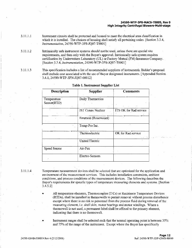
This specification includes a list ofrecommended suppliers of instruments. Bidder's proposal shall include cost associated with the use of Buyer designated instruments. [Appended Section 3.4.1, 24590-WTP-3PN-JQ07-00012]
Table 1. Instrument Supplier List
Description Supplier Comments
Temperature Daily Thermetrics Sensor(RTD)
1ST Conax Nuclear ITS OK for Rad service
Emerson (Rosemount)
Temp-Pro Inc.
Thermoelectric OK for Rad service ....
United Electric
Speed Sensor Air-Pax
Electro-Sensors
Temperature measurement devices shall be selected that are optimized for the application and environment of the measurement services. This includes installation constraints, ambient conditions, and process conditions of the measurement devices. The following describes the Buyer's requirements for specific types of temperature measuring elements and systems. [Section 3.4.5.2]
• All temperature elements, Thermocouples (T /Cs) or Resistance Temperature Devices (RTDs), shall be installed in thermowells to permit removal without process disturbance except where there is no risk to personnel from the process fluid during removal of the measuring element, i.e. shell skin, motor bearings and motor windings. Where a thermowell is not used, a permanent label shall be affixed to the primary element, indicating that there is no thermowell.
• Instrument ranges shall be selected such that the normal operating point is between 35% and 7 5% of the range of the instrument. Except where the Buyer has specifically
24590-G04B-F000I9 Rev 4 (2/12/2008) Page 12
Ref: 24590-WTP-3DP-G04B-00049
3.11.1.5
3.11.1.6
3.11.1.7
3.11.1.8
3.11.1.9
24590-WTP-3PS-MACS-T0005, Rev 0 High Integrity Centrifugal Blowers-Multi-stage
identified manufacturer and model, all the instruments shall be selected by the Supplier in accordance with guidelines provided herein. The instruments described below shall be selected to meet the required safety classification, specified quality, and the design criteria stated herein and in the primary equipment specification. The systems designed and fabricated shall meet the specified reliability and availability for each system or component.
• Sheathed RTDs with transmitters shall be used for remote temperature indication.
• RTD elements shall be Platinum with a nominal resistance of 100 Ohm at 0 °C (32 °F). The resistance-vs.-temperature characteristic curve shall conform to DIN 43760, IEC 60751 with a temperature coefficient of0.00385 ohms/ohm/°C. Three wire element design shall be used.
• RTDs shall be sheathed with Magnesium Oxide insulation. The sheath shall be 316SS and¼" diameter as a minimum. All T/Cs or RTDs shall be duplex design, spring loaded, and supplied with a connection head with internal grounding screw and external ground terminal. All elements shall be connected in the connection head.
• Temperature measurements using RTDs shall use remote mounted transmitters with the appropriate input/output voltage isolation and located in the field or panel to connect an isolated signal to the Buyer's or Supplier's control system. [Section 3.4.5.2.1]
The Supplier shall provide and install non:.contacting vibration and position sensor probes for machine monitoring of radial vibration. The installation of all bearing thermocouple and shaft position monitoring equipment shall be in accordance with API 670. Bearing thermocouples shall be type E calibration. [Section 3.4.5.16.1, Instrumentation, 24590-WTP-3PS-JQ07-T0001]
If required on Blower Data Sheet, speed transmitters shall have sensors of non-contact type. [Section 3.4.5.16.2, Instrumentation, 24590-WTP-3PS-JQ07-T0001]
All enclosures, cabinets, panels, and racks shall be designed and fabricated to be in full compliance with NFPA 70-1999. [Partial Section 3.6]
Access to enclosure internal components or equipment shall not require the use of hand tools. Access to any component within the enclosure for maintenance or replacement shall not be prevented by proximity to other components within the enclosure. Equipment mounted in the rear of the enclosure shall be on a back-panel and positioned to facilitate removal and replacement. Enclosure back-panels shall be fabricated from low-carbon steel and shall be finished with semi-gloss or gloss white paint. Enclosures shall be sized to allow clearance between the enclosed components, cables, print pockets, and components mounted on the door. [Section 3 .6.3, lnstrnmentation, 24590-WTP-3PS-JQ07-T000 1]
The enclosure grounding system shall be installed in conformance to IEEE Guide 1050-1996, section 5.3.1 "Single point grounding system". All instrumentation enclosures shall have an equipment safety ground bus and an isolated signal ground bus, except instrument junction box. Instrument junction box shall only have an equipment safety ground. The grounding bus shall be constructed with solid copper, and all connections shall be drilled and tapped. The ground bus shall be drilled and tapped for an additional 20 percent spare terminations. [Section 3.6.5, Instrumentation, 24590-WTP-3PS-JQ07-T0001]
24590-G04B-F00019 Rev 4 (2/12/2008) Page 13
Ref: 24590-WTP-3DP-G04B-00049

3.11.1.10
3.11.lJl
3.11.1.12
3.11.1.13
3.11.1.14
24590-WTP·3PS-MACS-T000S, Rev 0 High Integrity Centrifugal Blowers-Multi-stage
AH removable metal components, instruments, or electrical devices shall be connected via individual conductors to the equipment safety ground bus. Components shall not be grounded to each other via a common wire connecting the components to the equipment safety ground bus. Enclosure door and back-panel shall be connected to the equipment safety ground bus via individual conductors. Ground conductors connected to the equipment safety ground bus shall have an insulation color code of green. [Section 3.6.5, Instrumentation, 24590-WTP-3PS-JQ07-T0001]
The Supplier shall mount, connect and wire each instrument or control device such that adjustment, maintenance, removal and replacement may be accomplished in a safe manner without interruption of service to adjacent but unrelated equipment and without placing undue stress on installed wiring or devices. Accommodations for strain relief shall be made when routing wire to hinged enclosure doors and shall be wrapped with spiral wire wrap. [Section 3.6.6, Instrumentation, 24590-WTP-3PS-JQ07-T0001]
No more than two wires shall be connected to one terminal point and only if the terminal is rated for the two wires. Wire splicing shall not be used unless approved by the Buyer. Bridge or comb jumpers are preferred to wire jumpers on terminal strips. Jumpers shall not be installed on the field side of the terminal strip. [Section 3. 6. 6, Instrumentation, 24 5 90-WTP-3PS-J Q07-T000 1]
Terminal blocks shall be selected to accommodate the function and electrical requirements associated with each wiring application. They shall incorporate the following features:
1. Space saving design
2. Screw clamp wire connection
3. Single level configuration
4. Integral test facilities
5. DIN-rail (35mm) mounted [Section 3.6.6, Instrumentation, 24590-WTP-3PS-JQ07-T0001]
Isolating type terminal blocks shall be Weidmuller "W" series, Allen Bradley 1492-WKD3TP, Phoenix Contact, or Buyer approved equal. Non-isolating feed-thru terminal blocks shall be Weidmuller "W" series, Allen Bradley 1492-W4, Phoenix Contact, or Buyer approved equal. All terminal blocks. shall be identified by a unique terminal block number and approved by the Buyer. [Section 3.6.6, Instrumentation, 24590-WTP-3PS-JQ07-T0001]
For all enclosures, each incoming power supply shall have a manually actuated electrical power disconnect device mounted on/in the enclosure in an easily accessible location. The electrical power disconnect device may be a single device or multiple devices for individual circuits. Each device that uses 120 V AC for power shall have individual connections protected via rail mounted circuit breakers. The circuit breakers used for individual control or power circuit protection in the enclosure shall be thermal magnetic breakers such as W eidmuller CB, Allen Bradley type 1492-GH, Phoenix Contact, or Buyer approved equal. They shall be Dual-In-Line, DIN-rail mountable TS35, TS32, or equivalent. Power shall not be "daisy chained" from instrument to instrument; however, the bridge or comb jumpers may be used on the supply side of the circuit breakers. A fuse and circuit breaker directory shall be contained in a holder permanently affixed on the inside of each door or back-panel and protected by a clear window. [Section 3.6.6, Instrumentation, 24590-WTP-3PS-JQ07-T000 1]
24590-G04B-F00019 Rev 4 (2il2/2008) Page 14
Ref: 24590-\VTP-3DP-G04B-00049

3.11.1.15
3.11.1.16
3.11.1.17
3.11.1.18
3.11.1.19
24590-WTP-3PS-MACS-TOOOS, Rev 0 High Integrity Centrifugal Blowers-Multi-stage
All instrument signal cables shall be of the type and specification as listed in section 4.2.4-Instrumentation Cable Schedule. Power cable, wire size and type shall be in accordance with 1'.r:FPA 70 - 1999. [Section 3.6.6, Instrumentation, 24590-WTP-3PS-JQ07-T0001]
All wires and cables external to an enclosure shall be of the instrument tray cable (ITC) type, flame-retardant (passes IEEE 1202 vertical flame test), and have a 90 °C continuous rating in wet or dry locations. All cable insulation and jacket material shall be resistant to heat, moisture, impact, ozone, and meet or exceed the following requirements:
• 300 V rated for low voltage instrument cables (up to 120 V AC and 125 VDC)
• 600 V rated for power/motor control cables (up to 480 VAC and 250 VDC) [Section 3.6.6, Instrumentation, 24590-WTP-3PS-JQ07-T0001]
The wire insulation color for power wiring shall be of the following:
• Black-Ungrounded conductors more than 50 V AC
• White-Grounded conductors more than 50 V AC
• Green-Equipment grounding wire
• Green-Yellow tracer-Isolated instrument grounding wire
• Light Blue-Ungrounded supply voltage less than 50 V (DC or AC)
• Violet-Switched ungrounded voltage less than 50 V (DC or AC)
• White/Blue tracer -Grounded or return supply voltage less than 50 V (DC or AC)
[Section 3.6.6, Instrumentation, 24590-WTP-3PS-JQ07-T0001]
The enclosures shall be designed so that tools and test equipment may be used to accomplish all necessary adjustments, maintenance, cleaning, testing, and calibration. If specialized tools are needed for adjustments, maintenance, cleaning, testing, and calibration the Supplier shall provide two sets per order. Test points and calibration areas shall be accessible, clearly identified, and labeled. Adequate space shall be provided for removal and replacement of individual instruments or components located inside the enclosure. Equipment mounted in the rear of the enclosure shall be positioned to facilitate removal and replacement from the front of the enclosure. [Section 3.6.7, Instrumentation, 24590-WTP-3PS-JQ07-T0001]
The Supplier shall provide and install a suitable arc suppression device or kickback diode across switched loads unless the switching component includes inherent arc suppression. Kickback diodes shall be supplied and installed on all inductive DC loads. [Section 3.7.5, Instrumentation, 24590-WTP-3PS-JQ07-T0001]
All Supplier provided wiring shall be identified at each end with a numbering system that is cross-referenced on all appropriate drawings. The wire-numbering scheme shall be proposed by the Supplier with Buyer's concurrence. Ferrules or wire markers shall be indelibly and clearly marked in black on white plastic, heat shrinkable sleeves. Open markers or '"C" type sleeves that can be applied after a conductor is terminated will not be accepted. Junction box (JB) terminals shall have adequate space between them and the JB internal walls so connected cables and individual wire numbers can be easily read without disturbing the wiring within the JBs. [Section 3.7.8, Instrumentation, 24590-WTP-3PS-JQ07-T0001]
24590-G04B-F00019 Rev 4 (2/12/2008) Page 15
Ref: 24590-WTP-3DP-G04B-00049

3.11.1.20
3.11.1.21
3.1 Ll.22
3.11.1.23
3.11.1.24
3.11.1.25
3.11.1.26
3.11.1.27
3.11.1.28
24590-WTP-3PS-MACS-TO00S, Rev 0 High Integrity Centrifugal Blowers-Multi-stage
All cables provided by the Supplier shall be clearly identified with a heat shrink type label. [Section 3.7.8, Instrumentation, 24590-WTP-3PS-JQ07-T0001]
Instrument mounting locations shall be selected with consideration of both function operation and accessibility requirements for maintenance. Instrumentation should not be mounted on vibrating equipment or light duty support. Instruments shall not be mounted on handrails or safety railings. Instrument mounting bolting and hardware shall be 316 SS. Mounting brackets and stands for ITS instrumentation shall be qualified to the seismic requirements specified by the primary equipment specification. [Section 3 .8.8, Instrumentation, 24590-WTP-3PS-JQ07-T000 1]
Each instrument shall be installed so as to allow adequate safe access for both operation and maintenance. [Section 3.8.8.2,Instrumentation, 24590-WTP-3PS-JQ07-T0001]
Blowers shall be provided with a blower shaft speed sensor which shall include an "Air Pax/ AlTek" brand or Buyer approved equivalent shaft sensor, and any connecting cables or signal conditioners required to provide a 4-20mA signal output. Where required on the Blower Data Sheets, additional SMAR 1/F 302 Foundation Fieldbus converters shall be provided.
Blowers shall be provided with a "Daily Thermetrics" brand or Buyer approved equivalent three wire, dual element, 100 ohm platinum RTD to measure the temperature of each blower bearing. Temperature coefficient shall be 0.00385 ohms/ohm/°C. Generally all RTDs shall be duplex design, spring loaded, and supplied with a connection head with internal grounding screw and external ground terminal. All elements shall be connected in the connection head. Applications where a connection head is not feasible; general purpose RTD probes will be allowed.
Blowers shall come equipped with Bently Nevada transducers or Buyer approved equivalent to measure the vibration of the blower bearings. The instruments shall transmit a 4-20 mA signal proportional to the vibration.
Both temperature, speed, and vibration sensor wires shall be connected to terminal blocks provided by the Seller. Terminal blocks shall be installed in a separate electrical termination box for external connection to Buyer's cable(s). Seller shall provide sufficient terminals to allow landing and continuation of conductor shields.
The Buyer will provide power for the Suppliers' instruments. Each source will be delivered at 120 VAC, 1 phase, 60 Hz, grounded system. All other voltages required by Supplier shall be derived from the Buyer supplied 120 VAC, I phase, 60 Hz, grounded system. Inter-connecting wiring or cabling for packaged units furnished by Supplier, shall be terminated and tested according to this specification.
All internal enclosure wiring shall be neatly dressed in slotted PVC wire-ways. The wire-way shall be securely fastened to the enclosure back-panel. Supplier shall provide PVC wire-ways on the opposite side of field terminations to be used by the Buyer. Adequate space shall be provided around terminal blocks to allow the Buyer to train and terminate cables. The field side wire-way shall be designed for multi-core field cables with conductor size of #14 AWG.
3.12 Accessibility and Maintenance
3.12.1.1 Seller's recommended accessibility and recommended spares for each piece of equipment shall be included in the Seller's submittal.
24590-G04B-F00019 Rev 4 (2/12/2008) Page 16
Ref: 24590-WTP-3DP-G04B-00049

24590-WTP-3PS-MACS-T0005, Rev 0 High Integrity Centrifugal Blowers-Multi-stage
3.12.1.2 Seller shall provide the inspection and maintenance requirements with the recommended intervals to be performed by Buyer.
3.13 Accessories
3.13.1 Unitary Inertia Bases
3.13.2
3.13.2.1
3.13.2.2
3.13.2.3
3.13.2.4
3.13.3
3.13.3.1
3.13.3.2
When indicated on the Blower Data Sheets, blowers shall be provided with a unitary inertia base.
Vibration Isolators
When installation is specified on the Blower Data Sheet, the vibration isolators shall be Supplier specified and supplied. Supplier shall specify the isolator manufacturer and model number, spring minimum diameter, spring deflection, and spring restraint features on the Blower Data Sheet.
Submittal drawings shall show locations for vibration isolator placement on blower assemblies when installation is specified on the data sheet.
Each vibration isolator shall deflect equally under the conditions of dynamic loading.
Spring mounts shall be selected to provide 2 in. minimum deflection at design loading, and shall allow for 50 % additional travel to solid. Spring mounts shall incorporate seismic restraint capability for a seismic occurrence as defined in Specifications 24590-WTP-3PS-SS90-T0001, Seismic Qualification of Seismic Category I/II Equipment and Tanks or 24590-WTP-3PS-FB01-T0001, Structural Design Loads for Seismic Category III & IV Equipment and Tanks. Spring mounts shall include enlarged base plates for seismic anchoring.
Flexible Connectors
When specified on the data sheet, Supplier shall provide flexible connectors. Supplier shall specify the connector manufacturer and model number on the blower data sheet.
When specified on the data sheet, submittal drawings shall show locations for or placement of flexible connectors on blower assemblies
4 Materials
4.1 Construction
4.1.1 Materials of construction shall conform to the Blower Data Sheets as applicable.
4.1.2 Material test reports of chemical and physical properties shall be provided for all stress or pressure retaining components of the blowers, including the blower impeller and its components, blower shaft, and housings.
4.1.3 The ASME and/or ASTM material numbers and grades shall be identified and a Manufacturer's Material Certificate of Conformance shall be provided for scrolls, housing side plates, inlets, support framing integral to the blower, and weld filler metal. All material designations shall be indicated on the fabrication drawings and in the material lists.
24590-G04B-F00019 Rev 4 (2/12/2008) Page 17
Ref: 24590-WTP-3DP-G04B-00049
24590-WTP-3PS-MACS-TOOOS, Rev 0 High Integrity Centrifugal Blowers-Multi-stage
4.1.4 Blower bearing pedestals and motor bases shall be fabricated from structural steel shapes and plates properly reinforced for maximum rigidity, so they do not amplify motion from the blower or its components at any speed of operation ..
4.1.5 Blower housings shall be fabricated from materials specified in Blower Data Sheets.
4.2 Electrical
4.2.1 Low voltage power and control cables which are located external to the enclosures and not integral to the components shall be stranded copper, 600 V type XHHW-2 or Buyer-approved equivalent.
4.2.2 Internal enclosure wiring shall be stranded copper, flame-retardant, 600 V, synthetic heat resistant (SIS), or machine tool wire (MTW), or high-flexible thermoset.
4.2.3 Electrical equipment on the packaged unit shall be grounded to the package unit skid.
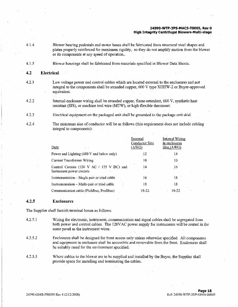
4.2.4 The minimum size of conductor will be as follows (this requirement does not include cabling integral to components):
Duty
Power and Lighting (480V and below only)
Current Transformer Wiring
Control Circuits (120 V AC / 125 V DC) and Instrument power circuits
Instrumentation - Single pair or triad cable
Instrumentation Multi-pair or triad cable
Communication cable (Fieldbus, Profibus)
External Conductor Size (AWG)
12
10
14
16
18
18-22
Internal Wiring in enclosures Size (AWG)
14
10
16
18
18
18-22
4.2.5 Enclosures
The Supplier shall furnish terminal boxes as follows:
4.2.5.1
4.2.5.2
4.2.5.3
Wiring for electronic, instrument, communication and signal cables shall be segregated from both power and control cables. The 120V AC power supply for instruments will be routed in the same panel as the instrument wires.
Enclosures shall be designed for front access only unless otherwise specified. All components and equipment in enclosure shall be accessible and removable from the front. Enclosures shall be suitably rated for the environment specified.
Where cables to the blower are to be supplied and installed by the Buyer, the Supplier shall provide space for installing and terminating the cables.
24590-G04B-F00019 Rev 4 (2/12/2008) Page 18
Ref: 24590-WTP-3DP-G04B-00049
24590·WTP-3PS·MACS-TOOOS, Rev 0 High Integrity Centrifugal Blowers-Multi-stage
4.3 Prohibited Materials
4.3.1 Bronze, copper, lead, zinc, tin, antimony, cadmium, or other low melting point metals, their alloys, or materials containing such metals as their basic constituents or molybdenum, and materials with halogen content of more than 200 ppm shall not be used in direct contact with stainless steel.
4.3.2 Asbestos and Teflon shall not be used in any component of the blowers or accessories.
4.3.3 Certain chemicals and materials are restricted from use at WTP. Restricted chemicals and materials are given in 24590-WTP-LIST-CON-08-0001, Restricted Materials List. Inclusion of these chemicals/materials requires specific authorization from the Buyer (WTP Safety Assurance).
5 Fabrication
5.1 Fabrication of Blowers
5.1.1 Blower wheels/ impellers shall be of the type and fabricated from materials specified in Blower data sheets.
5.2 Welding
5.2.1 All fabrication, welding, inspection and repair procedures of blower wheels, blower housing, housing framing and supports shall conform with the following, as applicable:
• A WS D 1.1, Structural Welding Code, Steel
• AWS D1.3, Structural Welding Code, Sheet Steel
• A WS D 1.6, Structural Welding Code, Stainless Steel
• A WS D9.1, Sheet Metal Welding Code
• AWS D14.6, Welding of Rotating Elements of Equipment
5.2.2 Repairs required as a result of weld rejection by either Buyer or Seller's final inspection shall be fully documented in accordance with Seller's QA program. Weld repair records shall be included with document package.
5.2.3 Welding procedures and procedure qualification records shall be submitted to Buyer for review and permission to proceed prior to use. Each procedure shall be prepared and qualified in accordance with the requirements of the above listed standards or ASME B & PVC, Section IX.
5.2.4 All welded seams on the pressure boundary of the unit shall be continuously seal welded.
24590-G04B-F00019 Rev 4 (2/12/2008) Page 19
Ref: 24590-\VTP-3DP-G04B-00049
6 Tests and Inspections
6.1 General
24590·WTP-3PS·MACS-T0005, Rev 0 High Integrity Centrifugal Blowers-Multi-stage
Multi-stage blower performance testing shall be in accordance with ASME PTC-10-1997.
Seller shall conduct and shall be responsible for the shop tests called for in this specification and in applicable standard and referenced documents. Seller shall furnish all facilities necessary for the performance of such tests.
Seller shall submit an inspection and test plan for Buyer review and approval.
6.2 Environmental Equipment Qualification
Environmental equipment qualification of the blowers, motors, instruments, and electrical accessories shall be conducted in accordance with specifications, 24590-WTP-3PS-JQ06-T0005, Engineering Specification for Environmental Qualification of Control and Electrical Systems and Components .
6.3 Seismic Equipment Qualification
Seismic qualification of the design of blowers shall be in accordance with the methods and procedures described in Specification 24590-WTP-3PS-SS90-T0001, "Seismic Qualification of Seismic Category I/II Equipment and Tanks", or 24590-WTP-3PS-FB01-T0001, "Structural Design Loads for Seismic Category III/IV Equipment and Tanks".
In addition to seismic analysis, seismic testing of a sacrificial unit to determine operability shall be required when the Environmental Qualification Data Sheet states the equipment must be operational after a seismic event. Material from the sacrificial units shall not be used in tagged equipment (permanent plant equipment).
6.4 Personnel Qualifications
6.4.1 Personnel performing nondestructive examination or reviewing nondestructive examination results shall be qualified in accordance with ASN1-SJ\TT-TC-IA, Level II or Level III. Qualifications of personnel performing inspections and tests shall be verified by the Seller.
6.5 Non-Destructive Examinations
6.5.1 Seller shall perform Non-Destructive Examinations. Non-Destructive Examinations may include visual, ultrasonic, radiographic, magnetic particle, liquid penetrant and eddy current examination procedures.
6.5.2 Non-Destructive Examination procedures shall be submitted to Buyerfor review and permission to proceed prior to use.
6.5.3 All pressure boundary parts made by casting shall be demonstrated to be surface-defect free by penetrant examination using Type I Method A techniques in accordance with ASME BPVC Section V.
6.5.4 All welds shall be 100% visually (VT) and liquid penetrate (PT) examined.
24590-G04B-F00019 Rev 4 (2/12/2008) Page 20
Ref: 24590-WTP-3DP-G04B-00049

24590-WTP-3PS-MACS-T0005, Rev 0 High Integrity Centrifugal Blowers-Multi-stage
6.6 Shop Tests
6.6.1
6.6.1.1
6.6.2
6.6.3
6.6.4
Buyer's inspector will indicate tests and inspections that the inspector intends to. witness after review of Seller's work plan. Seller shall perform standard factory tests, which, as a minimum, includes the following tests listed in sections 6.6.1 through 6.6.6, as well as tests called out in referenced specifications for the motors.
All test results shall be certified, documented, and submitted to Buyer for review, and permission to proceed. All test reports shall be accepted by Buyer based on the acceptance criteria outlined in the Supplier's test procedures. Acceptance of a test report shall be confirmed by receiving a status of "Work may proceed" from the Buyer.
The inspector may witness the following required shop tests:
Test for blower performance. Performance testing shall be done on one (1) of similar size blowers.
Multi-stage blower performance ratings may be based on testing in accordance with ASME PTC-10-1997. Inspection and test procedures shall be submitted to Buyer. Test records and results shall be certified.
Functional performance test for electrical equipment.
Vibration performance shall be checked and reported at 10% increments of full speed blower tests. Vibration testing shall not be performed within +/- 20% of the blower's critical speed.
A meg-ohm test of all wires shall be performed prior to termination of all wires pulled into conduit. The meg-ohm test results shall be certified, documented, and submitted to Buyer for review.
6.6.5 A continuity check of all wiring shall be performed to verify conformance with Seller's wiring schematics. The continuity check test results shall be certified, documented, and submitted to Buyer for review.
6. 7 Site Tests
Buyer startup personnel will perform test after initial installation. Buyer may request Seller assistance during startup.
7 Preparation for Shipment
7.1 General
Blower assemblies shall be packaged, shipped, handled and stored in accordance with ASME NQA-1, Part II, Subpart 2.2, Article 302, Levels of Packaging, at the following levels:
Level B:
• Blower assemblies with motors
• Motors in packages separate from the blower
24590-G04B-F00019 Rev 4 (2/12/2008) Page 21
Ref: 24590-WTP-3DP-G04B-00049

Level C:
24590-WTP-3PS-MACS-T000S, Rev 0 High Integrity Centrifugal Blowers-Multi-stage
• Blower assemblies without motors and adjustable speed drives
7.2 Cleanliness
Seller's cleaning procedures shall be submitted to Buyer for information. Prior to surface preparation and coating application, visually examine welds, the blower impeller, gas stream surfaces of the blower housing, and the gas stream surfaces of all furnished accessories. Remove all dirt, oil, and grease, loose mill scale, weld spatter and other foreign matter on surfaces to be painted in accordance with Seller's cleaning and coating procedures.
7.3 Painting and Special Protective Coatings
7.3.1 See Attachment B
7.4 Tagging
A stainless steel nameplate shall be attached to each centrifugal blower showing the manufacturer's name, shop location, date of manufacture, serial number, equipment rating, equipment tag numbers, weight of assembly and purchase order number. Instruments shall be identified with Buyer provided tag numbers.
7.5 Packaging
Packaging shall be at the ASME NQA-1, Part II, Subpart 2.2, Article 302, Levels of Packaging, at levels in Section 7 .1 above.
7.6 Documentation
Seller shall ensure that appropriate documentation is prepared and, if required, signed by the appropriate person(s). The shipping documentation shall accurately reflect specific traceability to the items being shipped. Drawings (wiring diagrams), showing external terminations for Buyer use to connect to Seller provided instrumentation shall be marked with the Buyer's instrument tag numbers.
8 Quality Assurance
The quality assurance program requirements of this specification are those specified in ASME-NQA-1 marked as applicable in Supplier Quality Assurance Program Requirements (SQAPR) Data Sheet attached to the material requisition, those specified in ASME NQA-1, Part II, Subpart 2.2, QA Requirements for Packaging, Shipping, Receiving, Storage and Handling ofltems for Nuclear Power Plants, and those specified in 24590-WTP-3PSG000-T000 1.
8.1 QA requirements specific to item(s) or service
8.1.1 The supplier shall have in place a QA program meeting the applicable requirements of Part I of ASME-NQA-1 (2000). Quality Assurance Program Requirements datasheets attached to the MR define the requirements based upon the type or scope of work to be performed. The supplier shall
24590-G04B-F00019 Rev 4 (2/12/2008) Page 22
Ref: 24590-WTP-3DP-G04B-00049

24590-WTP-3PS-MACS·TO00S, Rev 0 High Integrity Centrifugal Blowers-Multi-stage
document and implement a QA program that is in compliance with these requirements. Each supplier is required to flow-down required QA program requirements to each successive tier in the supply chain. The supplier shall submit his QA manual with his bid.
8.1.2 The successful bidder must pass a pre-award survey by the Buyer. Supplier shall demonstrate that their quality program is in compliance with the procurement quality requirements listed in Quality Assurance Program Requirements Datasheets. The Supplier shall allow Buyer, its agent, and DOE access to their facility and any lower tier subcontractor's facility and records pertaining to this purchase order for the purpose of QA Audits and Surveillance at mutually agreed times.
8.2 Supplier Deviation
8.2.1 Each supplier shall be required to identify and promptly document all deviations from the requirements of the procuring documents. In addition, the supplier shall be required to described the recommended disposition based on appropriate analysis. Submittals of request for deviations from lower-tier suppliers shall be through the prime supplier to WTP.
8.2.2 Supplier-proposed deviations from procurement documents shall be initiated by use of Supplier Deviation Disposition Request (SDDR) fonn.
9 Configuration Management
Equipment and/or components covered by this specification are identified with Component Identification System numbers shown in Blower Data Sheets. Each item shall be identified in accordance with Section 7.4, Tagging.
10 Documentation and Submittals
10.1 General
10.2
10.2.1
10.2.1.1
Seller shall submit to Buyer Engineering and Quality Verification documents in the forms and quantities shown in Form G-321-E, Engineering Document Requirements, and Form G-321-V, Quality Verification Document Requirements, attached to the MR.
Submittals
The Seller shall submit the following:
Drawings
Drawings shall show the following information:
The outline dimensions of blower, including outline and detail drawings for each component (motor, etc). These drawings shall reflect the "as-shipped'' configuration of the equipment and instrumentation. As a minimum, interface control drawings shall contain overall dimensions of the blower and motor, materials of construction, instrumentation interfaces and equipment mounting information including bolt hole sizes and quantities of bolts required.
24590-G04B-F00019 Rev 4 (2/12/2008) Page 23
Ref: 24590-WTP-3DP-G04B-00049

10.2.1.2
10.2.l.3
10.2.1.4
10.2.1.5
10.2.1.6
10.2.1.7
10.2.1.8
10.2.1.9
10.2.1.10
10.2.1.11
10.2.1.12
10.2.1.13
10.2.1.14
10.2.2
10.2.2.1
10.2.2.2
10.2.2.3
10.2.2.4
10.2.2.5
10.2.2.6
10.2.2.7
10.2.2.8
24590-WTP-3PS-MACS· TOOOS, Rev 0 High Integrity Centrifugal Blowers-Multi-stage
Mounting dimensions and information required for the design of supports and foundations, including any special assembly instructions.
Operating weights of blower assembly including motor components.
The space required for the removal of components.
The locations of access doors.
The weights of individual components.
The locations and identification of parts that are included in the parts list.
Assembly drawings providing sufficient detail to facilitate assembly of the component parts of the blower.
Wiring schematic and control loop diagrams. Diagrams shall include wire gauges and fuse sizes applicable to the supplied units only.
The ASTM or equivalent designation for materials.
Interconnection diagram and cable schedule showing details of all internal connections and Buyer external connections. The Supplier's furnished cable schedule shall include service voltage and Class of Circuit per NEC Articles 725, 760 and 800 for each cable.
Blower performance curves at 60%, 80%, 100%, and 110% design speed at design conditions specified on the data sheets. Provide preliminary performance curves prior to submitting equipment drawings.
Blower performance curves including unstable operating surge region/limit.
Location and type of anchor bolts,
Procedures
Procedures are to be submitted to Buyer for approval prior to use and shall include:
Welding procedures
Procedures for repairs ofrejected items or parts.
Cleaning and coating procedures.
Electrical component performance test procedures
Seller's shipping preparation and storage procedures.
Seismic test procedure and blower performance test procedure.
Test procedures for blower housing and shaft leakage tests.
Test procedures for sound, over-speed, vibration, and mechanical running tests.
24590-G04B-F00019 Rev 4 (2/12/2008) Page 24
Ref: 24590°WTP-3DP-G04B-00049

10.2.2.9
10.2.2.10
10.2.2.11
10.2.3
10.2.3.1
10.2.3.2
10.2.3.3
10.2.3.4
10.2.3.5
10.2.3.6
10.2.3.7
10.2.3.8
10.2.3.9
10.2.3.10
10.2.3.11
10.2.3.12
10.2.4
10.2.4.1
10.2.4.2
10.2.5
24590-WTP-3PS-MACS-T000S, Rev 0 High Integrity Centrifugal Blowers-Multi-stage
Environmental equipment qualification test procedures in accordance with specifications, 24590-WTP-3PS-JQ06-T0005, Engineering Specification for Environmental Qualification of Control and Electrical Systems.
Commercial Grade Dedication Procedure
Commercial Grade Dedication Plans
Inspection and Test Reports
Records of repairs of rejected items or parts.
Welding inspection reports and welding repair reports if required.
Electrical component performance test reports
Blower housing and shaft seal leakage test reports
Blower performance test reports, including blower curves
Sound power levels
Blower wheel/shaft vibration, over-speed, and mechanical test reports
Environmental equipment qualification test reports in accordance with specifications, 24590-WTP-3PS-JQ06-T0005, Engineering Specification for Environmental Qualification of Control and Electrical Systems. ·
Seismic qualification reports in accordance with 24590-WTP-3PS-JQ06-T0003, Engineering Specification for Seismic Qualification of Seismic Category I Control and Electrical Systems and Components and 24590-WTP-3PS-FB01-T0001, Engineering Specification for Structural Design Loads for Seismic Category III/IV Equipment and Tanks.
NRTL field evaluation report per specification 24590-WTP-3PS-G000-T0019
Commercial Grade Dedication Packages per specification 24590-WTP-3PS-G000-T0019
NDE reports
Calculations
Seismic analysis/calculations shall be submitted for Buyer's review and permission to proceed. Calculations shall be in accordance with 24590-WTP-3PS-G0O0-T0014, Engineering Specification for Supplier Design Analysis.
Corrosion analysis and estimated design life report.
Manuals
Manuals and instructions shall include:
24590-G04B-F00019 Rev 4 (2/12/2008) Page 25
Ref: 24590-WTP-3DP-G04B-00049

10.2.5.1
10.2.5.2
10.2.5.3
10.2.5.4
10.2.5.5
10.2.6
10.2.6.1
10.2.6.2
10.2.7
10.2.7.1
10.2.7.2
10.2.7.3
10.2.7.4
10.2.8
10.2.8.1
10.2.8.2
24590-WTP-3PS-MACS-TOOOS, Rev 0 High Integrity Centrifugal Blowers-Multi-stage
Erection and installation manuals which provide complete, detailed procedures for installing and placing equipment in initial operation. The manuals shall include all erection and installation drawings.
Operation and maintenance manuals which provide complete, detailed descriptions of components and accessories with data sheets showing design, construction and performance data for equipment. Manuals shall include drawings required for operation, maintenance arid repair, maintenance requirements, instructions and operational troubleshooting guides. All manuals/drawings shall include OEM part numbers.
Instruction manuals shall cover all major components such as blowers, motors, controls, and instrumentation, including those purchased from a subcontractor. The Seller shall obtain such manuals and lists, and submit them to the Buyer.
The Seller shall provide instructions regarding site long and short and long term storage up to 5 years, and preparation and protection of equipment after installation and prior to operation.
Where manuals include information applicable to several components, sizes or models, nonapplicable information shall be lined-out.
Certificates of Conformance
Seller shall provide Certificates of Conformance demonstrating compliance with all applicable standards, specifications, and drawings. ·
Seller shall certify lifting eyes or lugs and/or spreader bars are suitable for the safe, balanced lifting, and handling of the equipment.
Schedules
Lists and schedules shall include:
Schedule of engineering, fabrication, and testing.
Parts list, and cost for parts and items subjectto deterioration and replacement. Seller to state shelf life and storage requirements for spare parts.
List of recommended spare parts.
Schedule of maintenance and part replacements required to maintain the equipment qualification in accordance with requirements in section 6 of specifications, 24590-WTP-3PS-JQ06-T000S, Engineering Specification for Environmental Qualification of Control and Electrical Systems.
Materials Certificates
Material Certification for components of the blowers shall be submitted as noted in Paragraphs 4.1.1, .,- , .. ,,,,., and 4.1.3.
Certificates of calibration referenced to NIST traceable standards required for any calibratable instrumentation provided with the equipment.
24590-G04B-F00019 Rev 4 (2/12/2008), Page 26
Ref: 24590-WTP-3DP-G04B-00049

24590-WTP-3PS-MACS-T0005, Rev 0 High Integrity Centrifugal Blowers-Multi-stage
10.2.9 Data
10.2.9.1
10.2.9.2
10.2.9.3
Data shall include:
Buyer's data sheets, completely filled out by the Seller, showing all information required to determine that the units are of the design and materials specified herein, including motor data sheets.
Buyer's equipment qualification data sheets, completely filled out by the Seller, showing all information required to determine that the units are of the design and materials specified herein, including motor data sheets.
Acoustic data report. Sound test data from similar equipment previously tested can be submitted in lieu of test for the purchased equipment.
24590-G04B-F00019 Rev 4 (2/12/2008) Page 27
Ref: 24590-WTP-3DP-G04B-00049

Attachment A
24590-WTP-3PS-MACS·T0005, Rev 0 High Integrity Centrifugal Blowers-Multi-stage
Noise Requirements for Fans and Blowers
24590-G04B-F00019 Rev 4 (2/12/2008) PageA-i
Ref: 24590-WTP-3DP-G04B-00049
Attachment A
24590-WTP-3PS-MACS-TO00S, Rev 0 High Integrity Centrifugal Blowers-Multi-stage
Noise Requirements for Fans and Blowers
1 Scope
This Attachment to the specification covers noise requirements for blowers, including all motors, equipment, and sub-systems furnished by the Supplier.
2 Permissible Noise Levels
The noise limit applies to operation of the Equipment at rated load or full capacity, and during restart and shut down. When the Equipment or a sub-system is operated cyclically or intennittently, the noise limits apply during all portions of the cycle.
The A-weighted sound pressure level at 3 feet from the surface of the blower casing shall not exceed 85 dB A. The limit applies on each of four sides of the blower at the elevation of the centerline of the blower, but no less than 3 feet above grade or the platform upon which the blower is mounted. All sound pressure level limits apply to each blower system taken as a whole, and as installed.
If the Supplier cannot meet the required A-weighted limit for sound pressure level, even in a free field, the Supplier shall provide the A-weighted level that they can and will guarantee. Estimated octave-band and A-weighted sound power levels of the blower inlet/discharge shall be provided.
24590-G04B-F00019 Rev 4 (2112/2008) PageA-1
Ref: 24590-WTP-3DP-G04B-00049
Attachment B
24590-WTP-3PS-MACS-T0005, Rev 0 High Integrity Centrifugal Blowers-Multi-stage
High Integrity Centrifugal Blowers-Multi-stage -Customized Coating Specification
Contents
1 Scope ................................................................................................................................... B-1
2 General ............................................................................................................................... B-1
2.1 Responsibility ..................................................................................................................................... B-1
2.2 Surfaces Not To Be Coated ................................................................................................................ B-2
2.3 Definitions ........................................................................................................................................... B-2
2.4 Safety ................................................................................................................................................... B-3
3 Applicable Documents ....................................................................................................... B-3
3.1 Codes and Standards ......................................................................................................................... B-3
4 Submittals ........................................................................................................................... B-4
5 Quality Plan ....................................................................................................................... B-5
5.1 General ................................................................................................................................................ B-5
6 Materials ............................................................................................................................. B-5
6.1 Coating Materials ............................................................................................................................... B-5
6.2 Manufacturer's Standard Coating ................................................................................................... B-6
6.3 Machined-Surfaces Coating .............................................................................................................. B-6
6.4 Coating Over Stainless Steel .............................................................................................................. B-6
6.5 Batch Information .............................................................................................................................. B-6
6.6 Abrasives ............................................................................................................................................. B-7
7 Application ......................................................................................................................... B-7
7.1 General ................................................................................................................................................ B-7
7.2 Pre-Surface Preparation .................................................................................................................... B-7
7 .3 Surface Preparation ........................................................................................................................... B-8
7.4 Coating Application ......................................................................................................................... B-10
7.5 Remedial Work ................................................................................................................................. B-11
24590-G04B-F00019 Rev 4 (2/12/2008) Page B-i
Ref: 24590-WTP-3DP-G04B-00049
24590-WTP-3PS-MACS-T0005, Rev 0 High Integrity Centrifugal Blowers-Multi-stage
8 Inspection ............................................................................................................................................................................................................................. B-11
8.1 General .............................................................................................................................................. B-11
8.2 Surface Preparation Inspection ...................................................................................................... B-13
8.3 Coating Application ......................................................................................................................... B-13
9 Storage, Handling and Shipping .................................................................................... B-14
9.1 Coating Materials ............................................................................................................................. B-14
9.2 Steel Items and Equipment .............................................................................................................. B-15
10 Docnmentation ....................................................................................................................................................................................................... B-15
Appendix C of Attachment B Materials/Coating Systems ................................................... B-16
Appendix D of Attachment B Coating Schedule .......................................................................................... B-17
Appendix F of Attachment B Coating Manufacturer's Product Identity Certification Record ............................................................................................................................................................................... B-18
Appendix G of Attachment B Surface Preparation and Coating Inspection Form .......... B-19
Appendix H of Attachment B Manufacturer's Standard Coating Data Sheet .................. B-20
24590-G04B-F00019 Rev 4 (2/12/2008) Page B-ii
Ref: 24590-WTP-3DP-G04B-00049
24590-WTP-3PS-MACS-TOOOS, Rev 0 High Integrity Centrifugal Blowers-Multi-stage
Attachment B - High Integrity Centrifugal Blowers-Multi-stage -Customized Coating Specification
Per 24590-WTP-3PS-AFPS-T0001, Rev. 4
ENGINEERING SPECIFICATION FOR 24590-WTP-3PS-MACS-T0005
NOTE: Only the sections and appendices contained in this Attachment B apply to the High Integrity Centrifugal Blower MR. For continuity and maintaining configuration control, the section numbers from the AFPS specification noted above have been retained; inapplicable sections have been deleted.
Additional clarifications have been added to Sections 1.1, 6.4.1, and Appendix C, Table 2, Notes la and 1 b, identified by an asterisk (*).
1 Scope
1.1 This specification defines the minimum requirements for Special Protective Coating (SPC) materials/coating systems, surface preparation, application, and inspection of protective coatings to be applied. Items and surfaces to be coated shall be coated in accordance with Appendix D of this specification. Unless indicated otherwise in the base technical specification/material requisition or purchase order, all coats will be shop applied. Finish color shall be * ANSI 70 Gray unless indicated otherwise in Section 2.0 of the Material Requisition (MR).
1.2 All Special Protective Coatings (SPC's) are designated as Commercial Grade (CM) and non-safety.
2 General
2.1 Responsibility
2.1.1 The SELLER shall supply all personnel, coating materials and all necessary surface preparation, application, inspection and other equipment as required.
2.1.2 The SELLER shall unload, inspect, and store all inbound steel items and equipment scheduled for coating when manufactured by others. Items found to be damaged or otherwise unsuitable for coating shall be identified and segregated for evaluation by the SELLER.
2.1.3 The SELLER shall store all coating materials, perform surface preparation, coating application and inspection in accordance with this specification and Buyer reviewed procedures. The coating systems and associated coating materials used shall be in accordance with Appendix D Coating Schedule or the Material Requisition (MR) when coatings are specifically identified.
2.1.4 The SELLER shall perform all inspections and tests contained in this specification as necessary prior to verification by the BUYER.
24590-G04B-F00019 Rev 4 (2/12/2008) Page B-1
Ref: 24590-WTP-3DP-G04B-00049

24590-WTP-3PS-MACS-TOOOS, Rev 0 High Integrity Centrifugal Blowers-Multi-stage
2.1.5 The SELLER shall provide application and inspection documentation for all coating work in accordance with this specification.
2.1.6 The SELLER shall provide environmental control equipment as necessary for coating application and curing.
2.1.7 The SELLER shall provide erection marking. Marks for color-coding of bulk materials and erection marking shall be fully compatible with the coating system specified.
2.1.8 The SELLER shall touch-up and repair defective or damaged coating in accordance with procedures submitted and reviewed by the BUYER.
2.1.9 The SELLER shall protect all coated surfaces prior to shipment and provide suitable coverings, pa-l3:E1£B:gi;~illll& and strapping to protect coated items during shipment.
2.1.10 The SELLER shall only use inspection equipment that is currently (in date) calibrated.
2.2 Surfaces Not To Be Coated
2.2.1 Hold back coating from weld areas-
2.2.1.2 Three (3) to Four ( 4) inches for shop welds when using epoxy or other types of organic coatings
2.2.1.4 Note - The above coating hold back dimensions are only for items previously coated prior to welding. These coating hold back dimensions do not apply to shop welds that will be coated after welding is completed. This Section of the shop coating spec does not have anything to do with coating hold back requirements associated with visual inspection of welds during hydro testing. Coating hold back requirements associated with weld inspection must come from the prevailing code.
2.2.1.5 If the coating hold back at field welds is greater than 50% of the surface area of the item then the item does not required shop coating, however the items shall be blasted to remove all mill scale.
2.2.1.6 The coating hold back shall be sufficient to expose the entire shop weld for visual inspection on items fabricated prior to coating.
2.2.2 Name and instruction plates, etc.
2.2.3 Rubber or similar nonmetallic parts.
2.2.4 Machined surfaces.
2.2.5 Non-Ferrous metals unless otherwise specified.
2.2.6 Stainless Steel surfaces, unless specifically required by the BUYER (areas where stainless steel is welded to carbon steel the coating overlap onto the stainless steel shall be approximately 1 inch or as otherwise specified.)
2.3 Definitions
2.3.1 Batch- A quantity of coating made in one production run. A unique batch number is assigned for each production run of the coating material, curing agent, zinc powders, HH~"',!.,L\l,;= and thinner.
24590-G04B-F00019 Rev 4 (2/12/2008) Page B-2
Ref: 24590-WTP-3DP-G04B-00049
24590-WTP-3PS-MACS-T00OS, Rev 0 High Integrity Centrifugal Blowers-Multi-stage
2.3.3 Dry Film Thickness (DFT)- The thickness of an applied coating, once dry or cured. Usually expressed in mils (each mil is 1/1000 ofan inch).
2.3.4 Fish (cratering)- Formation of holes or visible depression in the coating film. Usually from a contaminated particle on the surface prior to applying the coating.
2.3.5 Holiday- A Pinhole, skip, discontinuity, or void in the applied coating film.
2.3.7 Mfg. Std. Coating-A manufacturers standard coatings system applied to off the shelfitems or standard line items of routine manufacture that are not specifically manufactured for the WTP project.
2.3.8 NIST- National Institute of Standards and Technology.
2.3.10 Pinholes- Minute holes visible in the applied coating without magnification that appears to penetrate one or more layers of the coating film.
2.3 .11 Profile- The surface roughness resulting from surface preparation by abrasive blasting or other authorized methods. (Refer to Section -7.3.6).
2.3.13 Sag- The running of freshly applied coating on a vertical surface due to being applied too thick (Same definition for runs and drips)
2.3 .16 Training and Certification- Training shall include an understanding of the specification, work procedures and manufacturers published instructions. Certification shall include a documented performance test demonstrating quality work verifiable by the BUYER. (Refer to Sections 4.8, 5.1.7, 7.1.2, and 8.1.1.1)
2.4 Safety
2.4.2 The SELLER shall comply fully with OSHA Hazard Communication Standard 29CFR 1910. Material Safety Data Sheets (MSDS) for all materials, including thinners and cleaning solvents, shall be obtained from the materials manufacturer and upon request made available, at the place and time of work, for review.
2.4.3 The Volatile Organic Compound (VOC) content of all materials shall comply with Federal, State and Local or other Regulatory requirements.
3 Applicable Documents
3.1 Codes and Standards
The latest applicable edition of the following codes, standards, specifications or WTP procedures form a part of this specification.
3.1.1 American Society for Testing and Materials (ASTM)
ASTM R96; 02 ASTM D3276- 00; 05 ASTM D4285- 99 ASTM D44 l 7- 99; 03
24590-G04B-F00019 Rev 4 (2/12/2008)
Test for Relative Humidity by Wet-and-Dry Bulb Psychrometer Standard Guide for Painting Inspectors (Metal Substrates) Test Method for Indicating Oil or Water in Compressed Air Field Measurement of Surface Profile of Blast Cleaned Steel
Page B-3 Ref: 24590-WTP-3DP-G04B-00049
3.1.2
3.1.3
24590·WTP-3PS-MACS-T000S, Rev 0 High Integrity Centrifugal Blowers-Multi-stage
ASTM D4537- 96; 04; 04a Standard Guide for Establishing Procedures to Qualify and Certify Inspection Personnel for Coating Work Inspectors in Nuclear Facilities.
ASTM D4940- 98; 03 Test for Conductimetric Analysis of Water Soluble Ionic Contaminants of Blasting Abrasives
ASTM D5064-01 Standard Practice for Conducting a Patch Test to Assess Coating Compatibility
The Society for Protective Coatings (SSPC)
SSPC-ABI 6/1/97; 7/1/07 SSPC-PA2 5/1/04 SSPC-SPl 11/1/82; 11/1/04 SSPC-SPI0 11/1/04 SSPC-SPl 1 11/1/87; 11/1/04 SSPC-VIS 1 6/1/02; 11/1/04
Mineral Slag Abrasive Measurement of Dry Paint Thickness with Magnetic Gages Solvent Cleaning Near White Metal Blast Cleaning Power Tool Cleaning to Bare Metal Guide and Reference Photographs for Steel Surfaces Prepared by Dry Abrasive Blast Cleaning
Occupational Safety and Health Administration (OSHA)
OSHA29 CFR 1910 Occupational Safety and Health Standards
4 Submittals
4.1 SELLER shall prepare detailed written procedures for material receiving, marking, storage, handling, surface preparation, environmental control, application, curing, inspection, testing, touch-up/repair, application personnel qualification, inspector qualification, (G321- E, category 28.0) and proposed documentation forms as described within this specification. The final procedure and documentation forms shall be submitted and reviewed with BUYER's permission to proceed prior to the start of coating work. (G321-E category 15.0). Submittal requirements formanufacturers standard coating are found in Section 6.0.
4.2 The SELLER shall submit all procedures and verification documents in accordance with the purchase order (e.g., Appendix J, Form G-321-E. & V, Exhibit "D" located in the purchase order.).
4.4 The SELLER shall identify the specific products by manufacturer and catalog number and shall submit the coating manufacturer's latest published product data sheet, application u:11irFH,,'Flf-iH,s.,_!!c1ih=== and Material Safety Data Sheets (MSDS). Conflicts, if any, between the SELLER's normal procedures, the coating manufacturer's recommendations, and this specification shall be brought to the attention of the BUYER for resolution and written permission to proceed. (G321-E category 11.0)
4.5 The SELLER shall submit original or copies of original Coating Manufacturer's Product Identity Certification Records for each and every batch of coating material used on the WTP project (Appendix F). (Refer to G321V category 13.0)
4.6 The SELLER shall submit a daily inspection record as part of the work procedures that includes all the elements provided in Appendix G as a minimum. An entry for Wet Bulb is not required when the accepted device used to measure humidity and dew point does not require a wet bulb. (Refer to Section 8.1.9 and 10.2) (G321V category 15.0)
4.8 The SELLER shall provide a personnel training and certification plan for applicators and inspectors. (Refer to Section 2.3.16, 5.1.7, 7.1.2 and 8.1.1.1.).
24590-G04B-F00019 Rev 4 (2/12/2008) Page B-4
Ref: 24590-WTP-3DP-G04B-00049

5 Quality Plan
5.1 General
24590-WTP·3PS-MACS-T000S, Rev 0 High Integrity Centrifugal Blowers-Multi-stage
5.1.1 The SELLER shall control the quality of items and services to meet the requirements of this specification, applicable codes and standards, associated procurement documents, referenced herein. The SELLER shall prepare and maintain documentation to provide evidence of compliance with reviewed procedures and this specification. A copy of the coating inspection documentation shall be included in the shipping documentation.
5.1.2 The SELLER, including any lower-tier organizations engaged by him, shall be subject to surveillance inspection by the BUYER representative until completion or termination of the procurement. This surveillance inspection does not relieve the SELLER from the responsibility for conformance to the requirements of procurement documents, this specification and authorized procedures.
5.1.4 The BUYER representative shall be provided with a work activity schedule and shall be notified of all required inspection points prior to the scheduled date for coating activities (Refer to MR Section 5.0).
5. 1.5 If the SELLER' s proposed work plan or procedures differ from the requirements of this specification, the SELLER shall specifically identify and explain all differences in writing and submit them to the BUYER for review and verification prior to the start of work ( e.g., Supplier Deviation Disposition Request- SDDR).
5.1.6 All pre-established witness and hold points shall be witnessed by the BUYER unless a written waiver has been issued.
5.1.7 The SELLER's coating inspectors shall have previous experience in coating inspection and shall receive documented training in the specific project coating requirements, ASTM standards and other relevant standards including the reviewed work procedures. All coating inspectors working on steel items or equipment shall be trained and qualified meeting the requirements of Section 8.1.1.1.
6 Materials
6.1 Coating Materials
6.1.2 Coating materials including the primer, intermediate and finish coat on a given item, shall all be from the same manufacturer. One exception to this rule is when upgrading a Manufacturer's Standard (Mfg. Std.) coating using a compatible epoxy tie-coat and suitable topcoat coating system (refer to Section 6.2).
6.1.3 Appendix D Coating Schedule and Appendix C Tables contain the specified Special Protective Coatings for the WTP project. Appendix C contains the generic coating systems and approved coating materials.
6.1.4 Repair materials shall be the same as those originally used. Repair materials shall be in pre-measured units, and only complete kits shall be mixed. Splitting or breaking down pre-measured units of multi-component coating materials may be considered if the SELLER prepares a procedure that requires accurate measurement of all materials and Seller's Quality Control (QC) inspector monitoring/verification of each and every mix. This procedure must be submitted to the BUYER for review and permission.to proceed.
24590-G04B-F00019 Rev 4 (2/12/2008) Page B-5
Ref: 24590-WTP-3DP-G04B-00049
6.2 Manufacturer's Standard Coating
24590-WTP-3PS-MACS-TO00S, Rev 0 High Integrity Centrifugal Blowers-Multi-stage
6.2.1 Components and equipment which are normally mass-produced, inventoried, and supplied from stock generally have been coated with the Manufacturer's Standard Coating (Mfg. Std.) system. Included are small valves, pumps and rotating equipment, filters and electrical equipment such as switchgear, control panels, instrumentation, motors, transformers and electrical enclosures. Items and equipment which are specifically fabricated for the WTP project shall be coated per this specification unless the item is shown to be too delicate to properly coat per Appendix D or the specific requirements contained in the MR.
6.2.1.1 The SELLER may submit an alternate coating to the specified or Mfg. Std. System, by identifying the coating materials, surface preparation, application and inspection on Appendix H including the coating material's latest published technical data sheet and MSDS, to the BUYER for review and permission to proceed.
6.2.1.2 All Mfg. Std. Coatings must be identified on an Appendix H and submitted to the BUYER along with technical data sheets and MSDS'. A small, easily replaceable item where coating touch-up is not practical ( e.g., very small, too delicate, low cost and easily replaceable) and can only be purchased with the manufacturer's standard coating, an Appendix H Manufacturer's Standard Coating Data Sheet is not required.
6.3 Machined-Surfaces Coating
6.3.1 Machined surfaces not specified to be coated with a specific coating system shall be protected with a solvent cutback asphalt temporary preservative (Daubert Chemical Tectyl 891, EF Houghton Chemical Rust Veto 342 or authorized equivalent). Temporary preservative applied to carbon steel that is overlapped onto stainless steel must meet the same chemical requirements as listed in Section 6.4. All equivalents must be identified on an Appendix H form and submitted along with the manufacturer's latest published data sheet and MSDS for review and permission to proceed by the BUYER.
6.4 Coating Over Stainless Steel
6.4.1 All coating materials, thinners, solvents and cleaning materials used on SS shall be shown to comply with the following requirements:
1) Leachable halogen content shall not exceed 200 ppm.
2) The total sulfur content shall not exceed 400 ppm.
3) The total oflow melting point metals such as lead, zinc, copper, tin, antimony and mercury shall not exceed one (1) percent. Of this, mercury should not exceed 50 ppm. These low melting metals shall not be intentionally added during the manufacture of the coating.
*(ADDED for High Integrity Centrifugal Blowers MR): Sherwin Williams Macropoxy 646 and Carboline Carboguard 890 have been tested and meet the requirements above. Only these materials are approved for direct contact with stainless steel.
6.5 Batch Information
6.5.1 Each container of coating material used by the SELLER shall be marked with the following:
• The manufacturer's name
24590-G04B-F00019 Rev 4 (2/12/2008) Page B-6
Ref: 24590-WTP-3DP-G04B-00049
• The product designation • Batch or lot number • Location and date of manufacture • The shelflife expiration date
6.6 Abrasives
24590-WTP-3PS-MACS-T0005, Rev 0 High Integrity Centrifugal Blowers-Multi-stage
6.6.1 Abrasives for blast cleaning shall be clean, free of oil or contaminants, and dry. The particle size shall be capable of producing the specified surface profile. Mineral and slag abrasives shall meet the requirements of SSPC AB-1. The first batch/lot of bulk, non-packaged, abrasives shall be tested for water-soluble contaminants and the conductivity shall not exceed 500 micro siemens/cm when tested in accordance with ASTM D4940. As an alternate, a chloride ion test kit, such as the Chlor*Test "A" manufacturers by Chlor Rid International Inc, or BUYER accepted equal may be used. The maximum allowable chloride level is 200ppm.
6.6.2 When using reclaimed steel grit/shot abrasive, the particle size shall be capable of producing the specified angular surface profile (minimum 50% steel grit in original mix and all adds shall be 100% steel grit). Reclaimed abrasives already in use and the first batch/lot of new abrasive shall be tested for water-soluble contaminants and conductivity. Conductivity shall not exceed 500 micro siemens/cm when tested in accordance with ASTM D 4940. As an alternate, a chloride ion test kit, such as the Chlor*Test "A" manufactures by ChlOT Rid International Inc, or BUYER accepted equal may be used. The maximum allowable chloride level is 200ppm.
7 Application
7.1 General
7.1.1 It shall be the SELLER's responsibility to stop the surface preparation and coating at any time when conditions exist that might adversely affect the quality. The BUYER representative may reject any prepared or coated surfaces not in compliance with this specification.
7 .1.2 All painters ( e.g., surface preparation personnel and paint/coating material application personnel), shall be individually qualified and certified in accordance with the SELLER' s written description that includes classroom training and capability demonstration using the WTP project specification, and the SELLER' s procedures as reviewed by the BUYER.
7 .1.3 Care shall be taken to avoid blasting or grinding away critical markings, which identify welders, joint numbers, or other markings, which identify the item. Where such data appears in the area to be coated, it shall be protected. SELLER's are responsible for assuring their sub-suppliers are instructed concerning these requirements.
7.2 Pre-Surface Preparation
7 .2.1 Prior to mechanical cleaning, the surfaces to be coated shall be cleaned in accordance with SSPC SP 1 to remove oil, grease, dirt, and other foreign matter that can interfere with the proper bonding of the coating. Any remaining sharp edges, weld spatter, or burrs found after the start of coating work shall be completely removed by grinding or other means. Pneumatic tools shall not be used unless they are fitted with effective oil and water traps on the exhaust air. If the steel items or equipment was shipped or stored so that the surface could have been contaminated with soluble salts (e.g., above deck ship transport, truck transport on
24590-G04B-F000 19 Rev 4 (2/12/2008) Page B-7
Ref: 24590-WTP-3DP-G04B-00049

24590-WTP-3PS-MACS-TOOOS, Rev 0 High Integrity Centrifugal Blowers-Multi-stage
dirt roads close to ocean, storage), the area shall be pressure water washed (2,000-5000psi) with demineralized water to remove as much soluble salt contamination as possible prior to abrasive blasting.
7.3 Surface Preparation
7.3.1 Prior to the start of work, the SELLER shall examine all surfaces to be coated to determine their acceptability for the specified coating application. If the surfaces are found to be unacceptable, the SELLER shall return the surface to an acceptable condition. Coating work shall not commence until corrective action has been taken. Commencement of coating work prior to the taking of correctable action shall preclude any subsequent claim by the SELLER The BUYER may require corrective action at the SELLER's expense.
7.3.2 Prior to blast cleaning items to be coated, they shall be visibly dry with the surface temperature of at least 5°F above the dew point. When using automatic blasting equipment that recycles steel abrasive, the steel need only be visibly dry.
7.3.3 All surfaces to be coated shall be pre-cleaned per SSPC SP 1 where oil, grease, and other contaminants are present.
7.3.4 Abrasives shall meet the requirements of Section 6.6.
7.3.5 Surfaces to be coated shall be blast cleaned in accordance with the surface preparation requirements specified in Appendix D (e.g., SSPC SPlO). Where abrasive blasting will damage the items or is impractical, SSPC-SPl 1 Power Tool Cleaning to bare Metal may be substituted only in limited areas and only with BUYER's permission to proceed (e.g. SDDR).
7.3.6 Abrasive blasting carbon steel shall result in an angular surface profile LS to 3.0 mils deep as measured using a profile comparator or Testex Press-O-Film replication tape, in accordance with ASTM D44 l 7 method A or C.
7.3.6.1 Methods established for measuring surface profile produced by abrasive blast cleaning are not valid or conclusive onsurfaces that are excessively rough prior to blast cleaning (e.g. rough mill finishes, heavy rusting or pitting [SSPC-VIS 1 Condition D or rougher], cast surfaces, weld beads or physically damaged surfaces). Therefore, to accurately determine the surface profile produced by blast cleaning, profile measurements shall be taken in areas exhibiting the least surface roughness. For example, SSPC-VIS 1 preblast Conditions A, B or C typically result in a blasted surface that is acceptable for surface profile measurement.
7.3.6.2 If excessive surface roughness covers the entire item, then a smooth, clean ASTM A36 steel plate (e.g., SSPC-VIS 1 Condition A, B or C), approximately 6 inch square and at least 1
/ 4 inch thick, shall be blasted using the identical abrasive, pressure, nozzle, blasting equipment and method used on the actual item. The surface profile measured on the smooth plate is regarded as an accurate measurement of the profile produced by that blasting method, and shall be recorded as the surface profile for the actual item. A new plate shall be blasted and measured at a frequency accepted in the SELLER'S procedures (refer to Section 8.1.9).
7.3.7 Recycled abrasive blasting using a steel grit/shot mix is acceptable. The maximum amount of shot in the original mix shall be 50%. All additions of abrasive shall be steel grit. The stabilized working mix shall be maintained by frequent small additions of new grit abrasive commensurate with consumption. Infrequent
24590-G04B-F00019 Rev 4 (2/12/2008) Page B-8
Ref: 24590-WTP-3DP-G04B-00049

24590-WTP-3PS-MACS-TO00S, Rev 0 High Integrity Centrifugal Blowers-Multi-stage
large additions of grit shall be avoided. Steel grit or shot is not acceptable for use on stainless steel surfaces.
7.3.7.1 The working abrasive mix shall be maintained clean of contaminants by continuous effective operations of cleaning machine scalping and air wash separators. Reclaimed grit used for abrasive cleaning shall be tested for the presence of oil/grease by immersing a sample in clean tap water and checking for oil flotation. Tests shall be made at the start of blasting and at a minimum of every four (4) hours thereafter. If oil is evident, the contaminated abrasive shall be cleaned or replaced. All surfaces blasted since the last successful test shall be completely cleaned of contamination then re-blasted using clean abrasive.
7.3.8 Blast cleaning shall not be performed in the immediate area where coating or curing of coated surfaces is in progress. All surfaces and equipment, which are not to be coated, shall be suitably protected from blast cleaning.
7 .3 .9 Burrs, slivers, scabs, lamination, and weld spatter which become visible after blasting shall be removed. The tools and manner employed to remove weld defects and sharp edges shall not burnish or destroy the profile. If the profile or roughness is reduced, it shall be re-blasted to produce the profile and roughness as required. The exhaust of pneumatic grinders shall not impinge on the cleaned surface. If the surface becomes contaminated, it shall be cleaned of contamination and re- blasted. Carbon steel tools or implements specifically employed for coating surface preparation shall not be used on stainless steel surfaces.
7.3 .10 If visible rust occurs or if the cleaned surface becomes wet or otherwise contaminated, these surfaces shall be re-cleaned to the degree specified. Cleaned surfaces remaining uncoated overnight shall be visually reinspected 100% for required cleanliness prior t_o coating or shall be re-cleaned to the specified cleanliness prior to applying the coating.
7 .3 .11 After surface preparation is complete and before coating, pressurized air or a vacuum shall be used to remove all dust and abrasive residue. The air shall be clean and dry as verified in accordance with Section 8.1.6 so as not to contaminate the prepared surface.
7.3.12 Machined surfaces shall be wiped with clean solvent before the application of coating and shall be protected from damage due to blasting and coating operations.
7.3.13 Machined portions of pipe flanges and other machined mating faces which will not be exposed after final fit-up shall be masked or covered and protected from surface preparation and coating activities. The remaining part of the flange face and exposed surfaces shall then be blasted and coated (bolt holes need only to be sufficiently coated for visible coverage. No dry film thickness required.).
7.3.14 Equipment shall have all openings plugged, masked, and/or blinded sufficiently to protect internals before abrasive blasting. After the coating operation is complete all internals shall be blown clean and/or vacuumed to remove any dust or abrasive blast media that may have entered the coated equipment.
7.3.15 The abrasive mixture and the compressed air shall be clean, dry, and oil free. Moisture traps, in addition to oil and water extractors mounted on the compressor, shall be used in compressed air lines to remove oil and moisture from air close to the point of use. (Refer to Section 7.3.7.1 and 8.1.6)
7 .3 .16 All valves, valve actuators and motors that will be shop coated shall be blasted and coated prior to assembly. Areas of assembled items that are not coated prior to assembly and subject to damage during blasting must be carefully protected from abrasive damage or abrasive contamination.
24590-G04B-F00019 Rev 4 (2/12/2008) Page B-9
Ref: 24590-WTP-3DP-G04B-00049

7.4 Coating Application
24590·WTP·3PS-MACS-T000S, Rev 0 High Integrity Centrifugal Blowers-Multi-stage
7.4.1 The coating shall be applied in accordance with reviewed procedures (refer to Section 4.1 ). The coating manufacturer's recommendations for the application temperature and the curing temperature and times (between coats and after last coat) of the specified material shall become a part of this specification. Application and curing temperatures above or below the limits allowed by this specification (Refer to Section 7.4.4) shall be submitted to the BUYER for review (e.g., SDDR).
- 7.4.2 Coatings shall be applied using properly sized and type of equipment for the size & complexity of the item being coated. The equipment shall be clean with all components in good working order.
7.4.3 Surfaces that will become inaccessible shall be coated before assembly, tagging, fitting, or welding. Inaccessible surfaces includes lap joint flanges, nozzle necks, lap joint stub ends, lap rings, bolt holes, flanges for exchangers and vessels, and welded joints that become inaccessible after assembly.
7.4.4 Coatings shall be applied only when the surface to be coated is clean and dry. The substrate temperature shall be a minimum of 5°F above the dew point during coating application and until the applied coating is no longer moisture sensitive per the coating manufacturer's published data or written recommendations. The substrate and air temperature during coating application and curing shall be a minimum of 50°F (inorganic zinc primers 40°F) and a maximum of l l 0°F. The relative humidity during coating application shall not exceed 85 percent. Measure humidity in accordance with ASTM E 337 (Sections 1.0-19.0) or using an alternate method reviewed and accepted by the BUYER. Deviations from the above listed minimum and maximum substrate/air temperature and humidity limits may be allowed when in accordance with the coating manufacturer's published or written recommendations and are accepted by the BUYER. The one firm limit is that the minimum substrate or air temperature shall not be less than 35 °F regardless of the coating manufacturer's published or written recommendations.
7.4.5 The SELLER shall record all batch numbers for each coating component used along with other information necessary for the BUYER to relate the batch to the item for which it was applied. (Refer to Appendix G)
7.4.6 All coatings shall be thoroughly mixed until they are smooth and free from lumps, then strained through a screen of at least 30 mesh. Zinc filled coatings shall be continuously agitated from the time initially mixed and while being applied. Other coating materials shall be mixed in accordance with the coating manufacturer's published recommendations. All multi-component coating materials shall be in premeasured units. Splitting or breaking down pre-measured units is not permitted. See Section 6.1.4 for requirements for mixing repair materials.
7.4. 7 Alternating coats shall have a visible color difference to insure full coverage over previous coats. Touchup of individual small spots < 6 sq. in, do not require a visible color difference when individually marked for repair and the mark remains in place until the repair is accepted.
7.4.8 Dry film thickness of each coating shall be in accordance with Appendix C/Table 1 Acceptable Coating Materials or as specified in the MR. (Refer to Section 8.3.2 & 8.3.3).
7.4.9 Relative to the ambient and surface temperatures the minimum and maximum drying times between coats shall be in strict accordance with the coating manufacturer's latest published technical data sheets.
7.4.10 Runs, sags, voids, drips, overspray, loss of adhesion, bubbling, peeling, or inadequate cure are not permitted. Where possible, defects shall be corrected as detected during application of the coating.
24590-G04B-F00019 Rev 4 (2/12/2008) Page B-10
Ref: 24590-WTP-3DP-G04B-00049

24590-WTP-3PS-MACS-T0005, Rev 0 High lntegrity Centrifugal Blowers-Multi-stage
7.4.11 Spray equipment, brushes and rollers shall be cleaned using only manufacturer recommended solvents/cleaners.
7.5 Remedial Work
7.5.1 The completed coating on each item shall have the correct dry film thickness and shall be free of damage and visible defects.
7.5.2 Repair of Dry Film Thickness (DFT) deficiencies
7.5.2.1 Defects such as runs, sags, overspray and embedded particles shall be corrected by sanding to remove the defect. When the defects are in the finish coat, all areas sanded must be overcoated with the finish coat. If the DFT of primer or intermediate coat is reduced to less than the specified minimum, the area shall be abraded with 80 grit sand paper or flapper wheel and an additional layer of coating shall be applied until sufficient thickness is achieved. If noticed during application, the sags or runs may be brushed out.
7.5.3 Repair of Damage
7.5.3.1 All damaged and loosely adhering coating shall be removed and the surface thoroughly cleaned using 80 grit sanding disc, 80-grit flapper wheel or 3M Clean-N-Strip. Edges of the breaks shall be feathered and the resulting surfaces shall be roughened. The designated number of prime and finish coats shall be applied.
7.5.4 Loss of adhesion, delamination blisters, bubbling and fish eyes in the applied coating require the coating to be removed and reapplied in accordance with this specification.
8 Inspection
8.1 General
8 .1.1 The SELLER shall have the full responsibility for the coating application quality in accordance with this specification and shall be responsible for stopping work activities when conditions develop that could adversely affect the quality of the completed work. All work is subject to the BUYER's inspection surveillance.
8.1.1.1 All coating work inspection personnel shall be trained, qualified and certified in accordance with the SELLER's reviewed procedures. The inspectors shall meet or exceed the minimum capability requirements for a Level I coatings inspector as described in ASTM D4537 Section 6.2. The SELLER's inspector training, qualification and certification procedures and plan shall include classroom training on the WTP project specification, and the SELLER' s reviewed procedures using the guidelines provided in ASTM D5498. The SELLER's inspector must demonstrate his/her capability of using the inspection equipment and performing all the required inspections. Additional coating work inspection guidance is found in ASTM D3276 and ASTM D6237 which may also be used in developing procedures for training and certifying coating work inspectors.
8.1.2 The BUYER representative shall be the final authority on the specification compliance for surface preparation and material application. Any coating, which in the BUYER representative's judgment, has not been applied in conformance with this specification, shall be rejected.
24590-G04B-F00019 Rev 4 (2/12/2008) Page B-11
Ref: 24590-WTP-3DP-G04B-00049
24590-WTP-3PS-MACS-T0005, Rev 0 High Integrity Centrifugal Blowers-Multi-stage
8.1.3 The BUYER representative shall have access to each part of the process and shall have the right and opportunity to witness any of the Quality Control Tests.
8.1.4 The SELLER shall furnish the necessary testing and inspection instruments, properly calibrated and maintained. If equipment is suspected of being out of calibration, it shall be re-calibrated and certificates made available for verification to the BUYER. Such equipment shall be available for use by the BUYER in conducting surveillance of the work. Calibration of testing and Inspection instruments shall be traceable to NIST or Buyer authorized alternative standards.
8.1.5 The SELLER shall halt the coating work and make corrections to the procedures, as necessary to correct repetitive faults found in the work.
8.1.6 Prior to using compressed air, the quality of the air downstream of the separator shall be tested in accordance with the requirements of ASTM D4285 by blowing the air onto a clean white blotter or cloth for two (2) minutes at a distance of no more than (12) inches to check for any contamination, oil, or moisture. "This test shall be performed at the start of work and every 4 hours thereafter". The test shall also be made after any interruption of the air compressor operation or as required by the BUYER. The air shall be used only if the test indicates no visible contamination, oil, or moisture. If contaminants are evident, the equipment deficiencies shall be corrected and the air stream shall be re-tested. Moisture separators shall be bled continuously. All lines shall be tested individually prior to use. Surfaces determined to have been blown down or blasted with contaminated air shall be cleaned of all contamination then re-blasted with clean air and abrasive. Coatings determined to have been applied using contaminated air shall be removed and reapplied using clean air.
8.1.7 Inspection points shall be established as follows:
• Prior to the start of work. • Immediately following the surface preparation • Immediately prior to the coating application • Following the application of each coat • Following the curing of the coating • Final inspection and sign-off, in accordance with the project requirements
8.1.8 Any defects disclosed by inspection shall be re-inspected after correction.
8.1.9 The SELLER shall keep the records indicated below, and submit these records to the BUYER (refer to Section 4.6 and Appendix G). The following lists the frequencies:
Coatine/lnsoection Sten 1. Pre-Surface Prep
Surface Preparation
Profile
2. Environmental/ Air Quality
3. Recirculated Abrasive
24590-G04B-F00019 Rev 4 (2/12/2008)
Reauired Freauencv 100% visual on Pre- Surface
100% on Surface Prep/Cleanliness
Profile first item of each type per shift and every 20 items thereafter or other frequency as BUYER accepted in SELLER's procedures.
At the start of each work and every 4 hours thereafter or more often during changing conditions.
At the start of work and every 4 hours thereafter
Page B-12 Ref: 24590-WTP-3DP-G04B-00049

4. Thickness Per SSPC P A2
5. Visual on Applied Coating.
8.2 Surface Preparation Inspection
24590-WTP-3PS-MACS-TOOOS, Rev 0 High Integrity Centrifugal Blowers-Multi-stage
On large items five (5) spot reading per 100 sq.ft.
On items< 100 sq.ft. four (4) spot readings
On items less than 4" (valves, fittings, components, etc) two (2) spot readings,
For repair spots< 6 sq. inches and> l sq. inch. Two (2) spot readings
For repair spots< I sq. inch one (1) spot reading
For small chips/nicks/scratches and pinhole size repair spots need only a visual.
For complex surfaces such as structural steel (steel beams) the frequency of dry film thickness readings shall be in accordance with SSPC-PA2 Appendix 3 sectionA3.4.1 excluding any readings on the flange toes. In accordance with figure A.3 "The Surface of a Steel Beam" the follo1wing locations are acceptable for the test readings- 1, 3, 4, 5, 7, 9, 10 and 11; and the following locations are excluded from test readings- 2, 6, 8, 12. For beams less than 20'-0" two (2) sets of8 spot readings shall be taken. For beams 20' -0" thru 60' -O" three (3) sets of 8 spot readings shall be taken.
100% of all items
8.2.1 Verify environmental conditions and compressed air quality (refer to Section 7.3.2, 8.1.6).
8.2.2 Verify recirculated grit is grease and oil free (refer to Section 7.3. 7).
8.2.3 Verify surface cleanliness and profile (refer to Sections 7.3.5, 7.3.6 and 8'1.9).
8.2.4 Grease free chalk shall be used to mark local areas, which do not meet the specified requirements (e.g., soapstone and crayons are not acceptable).
8.3 Coating Application
8.3.1 Environmental conditions and compressed air quality shall be verified per Sections 7.3.2, 7.4.4, 8.1.6 and 8.1.9.
8.3.2 Dry coating thickness (DFT) shall be measured with a magnetic film thickness gage such as an ElektroPhysik "Milcrotest" or Positector 2000, Positector 6000 or BUYER authorized equal in accordance with SSPC PA2. The number and location of dry film thickness readings shall be in accordance with section 8.1.9.4.
8.3.2.1 The gage shall have an appropriate range that is suitable to measure the thickness expected and record calibration accuracy in accordance with SSPC PA 2 at the start of work, against certified coating thickness calibration standards for non-magnetic coating of steel, traceable to NIST or BUYER authorized alternative
24590-G04B-F00019 Rev 4 (2/12/2008) Page B-13
Ref: 24590-WTP-3DP-G04B-00049

24590-WTP-3PS-MACS-T0005, Rev 0 High Integrity Centrifugal Blowers-Multi-stage
standards. The calibration standards shall be in date, and 1.5 mil to 20.0 mil range, unless otherwise specified.
8.3.3 Any surface with a measured thickness outside of the limits described in Section 7.4.8 shall be rejected. These areas shall be reworked or re-cleaned and re-coated at the SELLER's expense. The average of the required number of readings shall be within the specified dry film thickness range. Any of the required spot readings may be as low as 80% of the minimum specified or 120% of the maximum specified as long as the average of all the readings is within the specified range. An individual spot reading that conforms to this criteria conforms to the specified dry film thickness.
9 . Storage, Handling and Shipping
9.1 Coating Materials
9.1.1 Coating materials shall not be stored in direct sunlight or exposed to inclement weather (e.g. rain, snow, sleet, freezing rain, dew point condensation, see also Section 9 .1.5). Materials shall remain under cover until ready to use.
9.1.3 Coating material shall be delivered in manufacturer's original unopened containers. Each container shall be clearly identified with the manufacturer's name, product designation, batch number, date of manufacture and shelf life expiration date.
9.1.4 The maximum shelf life allowed for coating materials used on the WTP project is 24 months from the date of their manufacture. Coating materials that are older than 24 months or that exceed the manufacturer's published shelf life, if less than 24 months, shall not be used and shall be placed on HOLD and segregated from other coating materials. A one-time shelflife extension of no less than three (3) months and no more than six (6) months, may be issued by the coating manufacturer. The shelflife extension shall be based on laboratory testing of retain samples taken at the time of manufacture or by testing a sample provided from the actual coating material in question. Where testing verifies an outdated coating material still complies with its original design criteria, it is acceptable for shelf life extension. Expiration date stickers, provided by the coating manufacturer, shall be affixed to each container prior to release from HOLD. The stickers shall include the product number, batch/lot number, the new expiration date and suitably marked to indicate that they came from the coating manufacturer. A new Appendix F shall be provided by the coating manufacturer that includes the test results and specifically indicates it was provided to document shelf life extension including new expiration date. Coating materials that have not been stored or handled in accordance with Sections 9.1.5, 9.1.6, 9.1.7 and 9.1.8, may not have their shelf life extended.
9 .1.5 Coating material shall be protected from moisture, direct sunlight and temperatures below 40°F or above 100°F unless otherwise allowed by the coating manufacturer's latest published instructions and verified by the BUYER.
9.1.6 Coating material containers where the airtight seal has been broken or any of the contents are lost, shall not be used and shall be clearly marked and segregated from useable coating material.
9 .1. 7 Coating material containers shall not be opened except for immediate use.
9.1.8 Unused material shall be returned to storage as soon as possible at the end of each workday. Materials left out for more than eight (8) hours in an uncontrolled storage area (areas without environmental controls that are exposed to ambient weather) shall not be used and shall be clearly marked and segregated from useable coating material.
24590-G04B-F00019 Rev 4 (2/12/2008) Page B-14
Ref: 24590-WTP-3DP-G04B-00049

24590-WTP-3PS-MACS-T000S, Rev 0 High Integrity Centrifugal Blowers-Multi-stage
9.1.9 All required coating material certifications (Appendix F forms) for each batch of material delivered to the SELLER shall be available at the time of material receipt. Materials delivered to the shop without the required documentation shall not be used and the SELLER shall tag and place discrepant materials into a hold area clearly separated from acceptable material. Once required documentation is received or otherwise corrected and found to be acceptable, the discrepant material may then be taken off hold status and used.
9.2 Steel Items and Equipment
9 .2.1 The SELLER shall be solely responsible for the condition of the steel items and equipment from the time they are received until they have been delivered to the BUYER.
9.2.2 All booms, hooks, clamps, forks, supports, and skids used in handling or storing coated items shall be designed and maintained in such a manner as to prevent any damage to the items or to the coating and shall be reviewed by the BUYER's representative. Chains and wire rope in direct contact with the coated items are not acceptable. Fabric lifting and tie down straps shall be used.
9.2.3 The SELLER shall inspect all items upon receipt for shipping and handling damage. Any visible damage observed at this point shall be noted on the receipt inspection report.
9.2.4 All coated steel items and equipment shall be stored on padded supports as necessary to preclude damage to the coating. The supports shall be properly spaced and leveled.
9.2.5 The BUYER's representative will have authority to stop any storage or handling activity, if there is a possibility of damage to the coating.
9.2.6 All steel items and equipment damaged by the SELLER shall be repaired in accordance with the specification at the SELLER's expense. Only repair procedures reviewed by the BUYER shall be used.
10 Documentation
10.1 The SELLER shall provide a record of all materials used (related to individual batch number- refer to Appendix F).
I 0.2 The SELLER shall provide a record of all required daily inspections (Example- Appendix G) that includes pre-surface preparation, compressed air cleanliness, environmental conditions, surface preparation and roughness, location of field repairs coated, application, visual inspection, dry film thickness, holiday testing and all touch-up/repair. This record shall include the coating and thinner materials used and the ID of the items coated to provide traceability.
10.3 All quality documentation shall be available for review by the BUYER representative within 24 hours from the time it is generated.
10.4 SELLER documentation forms or the way that the actual work will be documented shall be provided by the SELLER as part of the procedures submittal for review by the BlJYER.
10.5 Documentation shall be submitted in accordance with the requirements listed in Section 3 of the Material Requisition (MR).
24590-G04B-F00019 Rev 4 (2/12/2008) Page B-15
Ref: 24590-WTP-3DP-G04B-00049

24590-WTP-3PS-MACS-T000S, Rev 0 High Integrity Centrifugal Blowers-Multi-stage
Appendix C of Attachment B Materials/Coating Systems
TABLE 1- PREQUALIFIED COATING PRODUCTS Coating Generic Products
Dry Film Ameron Carboline Devoe Dudick Inter- Sherwin Thlclmess (mils)
Number national Williams
P02 Organic Zinc Epoxy 3.0-5.0 Amercoat Carbozinc 859 313 None Interzinc 52 Zinc Clad IV
Primer 68HS
P04 High Build Epoxy 4.0-6,0 Amercoat 385 Carboguard 224HS Protecto-Coat Intergard Macropoxy 646 890 330or300 475HS
NOTES to Table 1, Appendix C:
1) All versions of the above coating materials shall comply the WTP project VOC requirements of3.8 lbs./gal and shall also comply with more restrictive local VOC requirements where the work is being performed. In the event the listed coating materials or acceptable versions of the listed coating materials do not meet the local VOC requirements an alternate VOC compliant material may be submitted for review.
TABLE 2- COATING SYSTEM CODES SYSTEM D CODE
COATl P02
COAT2 P04
COAT3 P04
COAT4
NOTES to Table 2, Appendix C:
1) The surface preparation for all coating systems shall be SSPC SPl0 Near White Blast with a surface profile of 1.5 to 3.0 mils unless otherwise noted in this specification or the material requisition.
*la) System Code D shall be used for all carbon steel and cast ductile iron surfaces, including the mounting frame (skid). Only the exterior of the housing shall be coated. All stainless steel surfaces shall remain uncoated.
* 1 b) For shipment and storage, blow into the housing a sufficient quantity of Cartee 307 Powder needed for the housing volume, followed by sealing the housing with steel blind flanges (six-bolt pattern, with rubber gasket) to reduce corrosion in the housing interior. An alternate vapor inhibitor product may be submitted to BUYER for review and acceptance.
24590-G04B-F00019 Rev 4 (2/12/2008) Page B-16
Ref: 24590-\VTP-3DP-G04B-00049
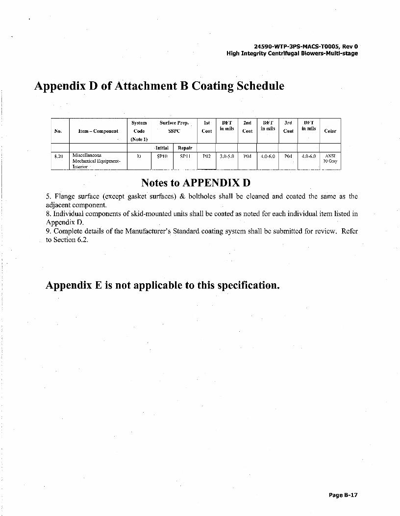
24590-WTP-3PS-MACS-T000S, Rev 0 High Integrity Centrifugal Blowers-Multi-stage
Appendix D of Attachment B Coating Schedule
System Surface Prep. 1st DFT 2nd DFT 3rd DFT
No. Item - Component Code SSPC Coat in mils Coat in mils Coat in mils Color
(Note 1)
Initial Repair
8.20 Miscellaneous D SPl0 SPll P02 3.0-5.0 P04 4.0-6.0 P04 4.0-6.0 ANSI Mechanical Equipment- 70 Gray Interior
Notes to APPENDIX D 5. Flange surface (except gasket surfaces) & boltholes shall be cleaned and coated the same as the adjacent component. 8. Individual components of skid-mounted units shall be coated as noted for each individual item listed in Appendix 0. 9. Complete details of the Manufacturer's Standard coating system shall be submitted for review. Refer to Section 6.2.
Appendix E is not applicable to this specification.
Page B-17
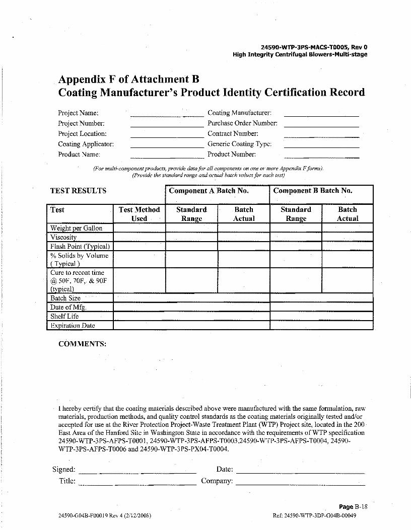
Appendix F of Attachment B
24590-WTP-3PS-MACS-T0005, Rev 0 High Integrity Centrifugal Blowers-Multi-stage
Coating Manufacturer's Product Identity Certification Record
Project Name: --------- Coating Manufacturer:
Project Number: Purchase Order Number: ---------Project Location: Contract Number: ---------Coating Applicator: --------- Generic Coating Type:
Product Name: Product Number:
(For multi-component products, provide data for all components on one or more Appendix F forms). (Provide the standard range and actual batch values for each test)
TEST RESULTS Component A Batch No. Component B Batch No.
Test Test Method Standard Batch Standard Batch Used Range Actual Range Actual
Weight per Gallon
Viscositv Flash Point (Typical)
% Solids by Volume (Typical) Cure to recoat time @50F, 70F, & 90F (typical)
Batch Size DateofMfg. Shelf Life Expiration Date
COMMENTS:
I hereby certify that the coating materials described above were manufactured with the same formulation, raw materials, production methods, and quality control standards as the coating materials originally tested and/or accepted for use at the River Protection Project-Waste Treatment Plant (WTP) Project site, located in the 200 East Area of the Hanford Site in Washington State in accordance with the requirements ofWTP specification 24590-WTP-3PS-AFPS-T000 1, 24590-WTP-3PS-AFPS-T0003,24590-WTP-3PS-AFPS-T0004, 24590-WTP-3PS-AFPS-T0006 and 24590-WTP-3PS-PX04-T0004.
Signed: --------------Tit 1 e: --------------
24590-G04B-F00019 Rev 4 (2/12/2008)
Date:
Company: -------------------------------
Page B-18
Ref: 24590-WTP-3DP-G04B-00049

Appendix G of Attachment B
24590-WTP-3PS-MACS-T0005, Rev 0 High Integrity Centrifugal Blowers-Multi-stage
Surface Preparation and Coating Inspection Form
REPORT NO: ____________ _ PROJECT: _____________ _ SUBCONTRACTOR/SELLER: _______ _ EQUIPMENT/AREA: __________ _ SUBSTRATE: STEEL/CONCRETE/OTHERENVIRONMENT AL CONDITIONS:
WORK ACTIVITY
TIME
DRY BULB TEMP. °F
WET BULB TEMP. °F
RH¾
DEWPOINT°F
SURFACE TEMP. °F
BLOTTER TEST
PRE-SURF ACE PREPARATION:
Page of
DATE: DAY: M T W T F S S SHIFT: INSPECTOR: COATING SPEC NO/REV: _______ _
I
SP-1 :________ MASKING/PROTECTION: ___ _ SURFACE DEFECTS: _____ _
SURFACE PREPARATION: METHOD: ______ _ ABRASIVE TYPE/SIZE/STORAGE: _____________ _
CLEANLINESS SPEC: ___ _ ACTUAL: ______ PROFILE SPEC: ___ _ ACTUAL: ___ _ EQUIPMENT: ______________________________ _
COATING MATERIALS & MIXING: PRODUCT(S) ______________________________ _
BATCH NO(S)/QUANTITIES/EXPIRATION DATE: _______ ~/ ______ ~/ ____ _
THINNERS/THINNING RATIO: _____________ ~/-~----~'-----STORAGE: ______ _ MIXING: _____ _ INDUCTION TIME: ________ _
MATERIAL TEMPERATURE: ______ _ POT LIFE EXPIRATION TIME: ________ _
COATING/LINING APPLICATION START TIME: ______ _ FINISH TIME: ________ _
COAT: PRIMER/PRIMER T.U./SECOND/SECOND T.U./THIRD/THTRD T.U./OTHER METHOD: ___ _ WFT: ___ _ RECOAT TIME/TEMP: ___ _ CURE TIME/TEMP: ____ _ EQUIPMENT: ______________________________ _
APPLIED COATING: VISUAL INSPECTION (FILM IMPERFECTIONS): ____________________ _
DRY FILM THICKNESS: SPEC: _____ _ ACTUAL: _____ _ METHOD: ______ _
HOLIDAY TEST:__ METHOD: ___ _ OTHER TESTING: __ _ METHOD: ______ _
TOUCH-UP AND REPAIR: ________ _ FINAL CURE: ____________ _
COMMENTS: ( Use reverse side or attach extra pages)
24590-G04B-F00019 Rev 4 (2/12/2008)
I INSPECTOR'S SIGNATURE/DATE
Page B-19
Ref: 24590-WTP-3DP-G04B-00049

"
24590-WTP-3PS-MACS-T0005, Rev 0 High Integrity Centrifugal Blowers-Multi-stage
Appendix H of Attachment B Manufacturer's Standard Coating Data Sheet
The SELLER proposes the following Manufacturer's Standard (Mfg. Std.) or alternate coating system that is suitable for the exposure conditions of steel items and equipment in radiation and non-radiation areas.
1. A Equipment Description: A. Tag Number _________________________________ _ B. Part(s) i.e. slcirt, shell, channels, lugs, etc.* C. Design/Operating Temperatures, designate °F or °C ....................... _______ 0~F~ ___ 0-'C"-----D. Does Equipment Receive Steam out (Yes/No), Temperature °F °C E. Insulated/Uninsulated F. Fireproofmg (Yes/No)
AG. Carbon Steel (CS), Stainless Steel (SS), other (List)
2. ASeller:
3. ASurface Preparation: SSPC No./Profile
4. Coating System Designation: (Code) First Coat
AA. Type of Coating ................ ________ _ "B. Coating Mfg./No. ** ......... ________ _ "C. Dry Film Thickness
(Min/Max in rnils)/(µm) ... _______ _ D. Wet/Film Thickness
(Min/Max in rnils)/(µm) E. Curing Method .................. ________ _
"F. Color ................................... ________ _ G. Dry to Recoat ................... ________ _ H. Pot Life ............................. ________ _ L. Thinner/% ....................... ________ _
I
Second Coat
5. Total DFT of System: (Mils/µm)(Min/Max) ................. ____ ----'-/ ---=Min=·=·-Max.
Third Coat
I
6. Material Storage: Temperature Requirements (Min/Max) __________ ;_/ ________ _
7. ShelfLife:_ Months
8. Application Environmental Limits: A. Temperature Ambient and Surface (Min/Max).......... / / B. Humidity (Min/Max) ......................................................................................................... ____ ~/ ___ _ C. Surface Temp 25°F above Dew Point temp. (Yes/No) .................................................... ________ _
9. Protection of surfaces that will be inaccessible after equipment installation (such as underside of base plates, interior of fans, vessels or equipment housings)
10. Rust Preventative for machined faces: (**Mfg./No.) ________ _
11. Quantity of touch-up coating supplied: -""""'lv-=-·o=n=--e _________ _
12. Additional information: (attach extra page as necessary)
* Use additional copies of this form for each part described in 1 above that requires a different coating system. A completed copy of this data sheet shall be submitted to CONTRACTOR/BUYER with the initial vendor data submittal.
** Include manufacturer's technical data sheets and MSDS for each proposed coating & preservative. /\ Mandatory data entry. Other entries should be completed where information is available from sub vendor or from coating material
technical data sheets.
24590-G04B-F00019 Rev 4 (2/12/2008)
Page B-20
Ref: 24590-WTP-3DP-G04B-00049