RITTIUM 3 RITTIUM 3P - Santehnika...5 REMARK: Each stove before packing requires the operation and...
28
RITTIUM 3 pellet stove RITTIUM 3P pellet stove Owners’s manual INSTALATION, ADJUSTMENT AND OPERATING INSTRUCTION EN 14785:2006
Transcript of RITTIUM 3 RITTIUM 3P - Santehnika...5 REMARK: Each stove before packing requires the operation and...

RITTIUM 3 pellet stove
RITTIUM 3P pellet stove
Owners’s manual
INSTALATION, ADJUSTMENT AND OPERATING INSTRUCTION
EN 14785:2006

2
CONTENT
1. ABOUT PELLET ....................................................................... Error! Bookmark not defined.
1.1 QUALITY OF PELLET ......................................................... Error! Bookmark not defined.
2. REMARKS BEFORE OPERATING THE STOVE ...................... Error! Bookmark not defined.
3. TECHNICAL CHARACTERISTICS ........................................... Error! Bookmark not defined.
4. BASIC FEATURES OF STOVE .............................................................................................. 7.
5. INSTALATION OF STOVE ........................................................ Error! Bookmark not defined.
6. CONTROL UNIT ....................................................................... Error! Bookmark not defined.
6.1. CONTROL UNIT AND REMOTE CONTROL ...................... Error! Bookmark not defined.
7. OPERATING THE STOVE ........................................................ Error! Bookmark not defined.
7.1 STARTING THE STOVE ..................................................... Error! Bookmark not defined.
7.2 INITIAL PELLET LOADING (LOAD PELLET) AND STARTING FIREError! Bookmark not defined.
7.3 STARTING FIRE ................................................................. Error! Bookmark not defined.
7.4 OPERATION MODE ............................................................ Error! Bookmark not defined.
7.5 THERMAL OUTPUT SETTING ........................................... Error! Bookmark not defined.
7.6 CHANGE OF ROOM TEMPERATURE ............................... Error! Bookmark not defined.
7.7 ACHIEVING OF SET ROOM TEMPERATURE ................... Error! Bookmark not defined.
7.8 STAND - BY MODE ............................................................. Error! Bookmark not defined.
7.9 TURNING OFF THE STOVE ............................................... Error! Bookmark not defined.
8. MENU ....................................................................................... Error! Bookmark not defined.
8.1 MENU STRUCTURE ........................................................... Error! Bookmark not defined.
8.2 TIME SETTING ................................................................... Error! Bookmark not defined.
8.3 MENU M2-1 PROGRAMING THE STOVE ......................... Error! Bookmark not defined.
8.4 MENU M3- LANGUAGE ...................................................... Error! Bookmark not defined.
8.5 MENU M4 - STAND BY ....................................................... Error! Bookmark not defined.
8.6 MENU M5 - SOUND ALERT ................................................ Error! Bookmark not defined.
8.7 MENU M6 - INITIAL PELLET LOADING .............................. Error! Bookmark not defined.
8.8 MENU M7 - CURRENT STATUS..................................................................................... 23.
8.9 MENU M8 - TECHNICAL CALIBRATION ............................ Error! Bookmark not defined.
8.10 MENU M9 - EXIT ............................................................... Error! Bookmark not defined.
9. ALARMS AND SOUND ALERTS .............................................. Error! Bookmark not defined.
10. CLEANING AND MAINTAINANCE ..................................................................................... 25.
WARRANTY…………………………………………………………………………………………27.

3
1. ABOUT PELLET
Pellet is an energy fuel with high energy efficiency that is produced in special technological process of milling,
drying and pressing of various materials of biological origin. As raw materials for its production can be used
wood from forestry waste, firewood, sawdust and other wood waste (wood pellets); the straw of wheat and
soybeans, corn and sunflower husks (agro pellets).
Nowadays, when the accent has been put on environmental protection and sustainable development, fuels
produced from biomass are increasingly gaining in importance.
Using pellets as a fuel material has multiple advantages either for the environment or, at the first place, for a
customer itself:
• Using one ton of pellets, for the same heating quantity, replaces 500 liters of heating oil, or 450 kg
of propane-butane, or 600 cubic feet of natural gas, or 4800 kilowatt-hours of electricity;
• It significantly reduces emission of harmful gases, such as: carbon dioxide, sulfur dioxide and
mercury, and the burning leaves only 0.5 - 1% of ash; • Wood pellet is made of 100% natural materials and contains no added binders, chemicals or
additives; • Compared with other fuels or using electricity, the use of pellets is much more cost-effective; • Pellet takes up far less space than coal and firewood.
1.1 QUALITY OF PELLET
The quality of pellets is of great importance for the stove. If the pellet is substandard and inadequate in size, it can bring to a poor performance of the stove.
Here are some advices on how to choose and store pellets:
• diameter of the pellets should be 6 mm and length about 30 mm; • use only wood pellets; • pellet should be cylindrical; • good quality pellet should quickly sink when thrown into a glass of water; • pellet is not adequate when in a bag of pellets you find a lot of dust or friable; • a pack of pellets should be hermetically sealed, because pellets absorbed humidity; • humidity must be less than 10%; • pellets are supposed to be stored in dry, well ventilated room, out of the reach of flammable
elements or devices which during operation create a high temperature
2. REMARKS BEFORE OPERATING THE STOVE
Always follow the references given in this chapter. The manufacturer doesn’t take a responsibility
for consequences in opposite cases. Not respecting the instructions of use and maintenance, you
lose your right to a warranty.
• Before operating the stove, please read this manual;
• Stove is used exclusively for heating;
• Keep the stove away from flammable materials;
• Keep the stove in dry places;

4
• Keep the children or pets away from the stove, because some parts emit high temperatures
and they can cause burns;
• do not touch the parts that emit a high temperature, such as smoke drain, glass, fire door,
the side;
• Use only a pellet which was originally made of wood;
• Stove should be cleaned only when it is cold (the stove is completely cooled after 30
minutes after turning off the stove);
• Stove should be cleaned only when it is disconnected from the power source on the main
switch (Chapter: basic parts of the stove);
• In the room where stove is placed, it is necessary to ensure a permanent supply of fresh air;
• Stove must be installed in accordance with these manual (Section: Instalation of the stove)
• Install the stove in accordance with the regulations in force in the relevant place, region or
country
• This appliance must not be used by anyone (including children) with limited physical,
sensory or mental skills or with little experience and knowledge, unless they are supervised
or have been instructed to use the device by the person in charge of its safety DO NOT
operate the stove while the door is open or if the glass is broken
• The stove must be used, adjusted and programmed by an adult. Errors or incorrect settings
may cause hazardous conditions and/ or malfunction
• Do not place laundry on the stove to dry. Clothes, papers and similar items should be kept
at a safe distance from the stove -Risk of fire
• Tampering of any nature or replacement of stove spare parts with non-original parts may
endanger the operator. TimSistem bears no civil or criminal liability for tampering or use of
non-original parts
• Large parts of the surface of the stove can get very hot (door, handle, glass, smoke outlet
pipes, etc.).Therefore, avoid touching these parts without wearing suitable protective
clothing or using appropriate measures, such as heat protective gloves or "hands cool" type
systems
• DO NOT operate the stove while the door is open or if the glass is broken
Stove and its packaging are made of materials that can be recycled. Stove, which is not in use any
more, should be put away in an adequate place or else you should call the service for waste
disposal. You must act according to a regulation in force in the country where the stove is placed.
For any defect you need to call a qualified technician. All defects must be removed by an
authorized service technician. In case that an unauthorized person repairs a stove, you will
automatically lose a warranty and any further repairs by an authorized service will be charged.

5
REMARK:
Each stove before packing requires the operation and safety control; therefore it’s possible to find
some burning remains in the firebox. It is also possible to find a small amount of pellets in the
store.
During the first firing can occur some paint burning, therefore it’s recommended to ventilate the
room well after.
FIREBOX SHOULD BE CLOSED WHEN EVER THE STOVE IS OPERATIONAL!
3. TECHNICAL CHARACTERISTICS
Technical characteristics are presented in following table:
Power kW 5 kW
Dimensions Rittium 3 (Wx D x H) mm 460 x 527 x 916
Dimensions Rittium 3P (W x D x H) mm 460 x 527 x 1012
Weight Rittium 3 kg 88
Weight Rittium 3P kg 96
Fuel Wood pellet Ø6 mm, L=30mm
Exhaust diameter mm 80
Draft Pa 12±2
Storage capacity kg 15
Voltage V 230 ± 15%
Frequency Hz 50
Electrical power during the operation W 55 - 160 *
Electrical power during the initialization W 400 - 450 **
Efficiency % 93.3
Reduced power kW 2,3
Fuel consumption-with nominal power Kg/h 1,1
Fuel consumption-with reducedpower Kg/h 0,6
CO emission reduced on 13% % 0,0133
Temperature of exhaust gasess oC 135
Dust mg/Nm3 48,4
Temperature during operation oC 5 - 60
Storage temperature oC -10 - 60
Max.rel.humidity without condensation % 95
* - depending of which fan is on, as well as the motor reducer
** - Emissions fan and lighter is on (400W), while motor reducer is occasionally turning ON
6
RITTIUM 3
RITTIUM 3P
Picture 1. Dimensions
1. Air inlet Ø50mm
2.Exhaust Ø80mm
1.Air inlet Ø50mm
2.Exhaust Ø80mm

7
4. BASIC FEATURES OF THE STOVE
Picture 2. Basic features.
1. Fire box doors 10. Storage cover
2. Door handle 11. Control unit and display
3. Door glass 12. Exhaust
4. Ashtray 13. Primary air inlet
5. Burning pot 14. Amin switch
6. Pedestal * 15. Socket
7. Lateral metal sheet 16. RS232 communication port
8. Top plate 17. Safety thermostat
9. Storage
* Only in version 3P

8
5. INSTALATION OF THE STOVE
With a stove you get the user manual, remote control, power cable. Parts that are included
with the stove are presented on Picture 3.
Picture 3.
Before you start installation of the stove, you must read carefully instructions for use and
maintenance get to know well a regional regulations and legislation, in order to apply them. You
must provide enough air in the room where the stove is placed in order to provide optimal
combustion.
Place the stove as close as possible to a smoke drain, where is also a power connection. The
stove should be away from any possible obstacles, like presented in Picture 4.
Picture 4.
Stove should be set 300 mm away from
the obstacle on its sides, 300 mm from
the back side, while the front side should
be at least 800mm away from obstacles.
Do not place any objects on the stove,
because they could be damaged by a
high temperatures that the stove emits.
Below the stove you can set sheet metal
or a thicker glass of minimal dimensions
700 x 800 mm. in a way that the front
part is longer than the stove itself.
The stove stands on adjustable feet which must be set so that the stove is stable. Feet are being
adjusted by simple unscrewing or twisting.
All appliances, which discharge combustion to the exterior, must have a proper flue. The same
flue must never be used for more than one appliance.
9
The tubes, which connect the stove to the flue, must be carefully sealed together, especially at the
connection point between the stove and/or cooker and the flue. We recommend the use of high-
quality tubes.
It is necessary and sufficient to provide sufficient air supplies to the chimney so that the stove
could to function smoothly. The easiest way to check whether the chimney is working well is to get
close to a smoke drain a lighter or a candle flame. If the flame is vertical as it was before, away
from the chimney, then you should check whether the chimney needs to be cleaned, or is there
some other problem in between. If the flame sways toward the mouth of the chimney, there is
quite sufficient air movement. All irregularities in the functioning of the chimney must be removed
before initializing the stove.
When connecting the stove with smoke drain and flue tubes, check carefully if all connections are
well sealed, so that gases do not to enter the room where the stove is located. Flue pipe must not
be too drawn into the chimney.
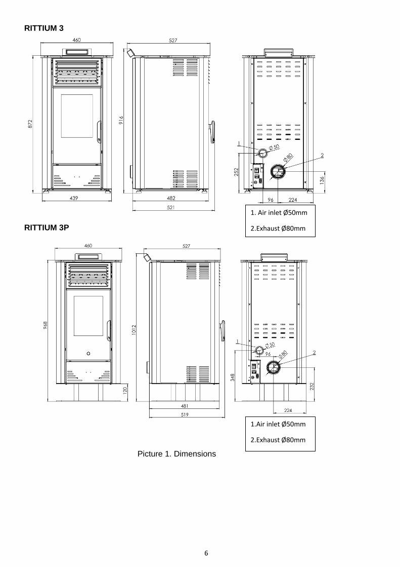
With the stove you get and the power cord. Stove is connected to the power source voltage of
230V and 50Hz. Stove must be connected only to the required socket. Figure 5 shows how the
stove is connected to a power source. Before plugging in the cable, check if the main switch is set
to the position 0.Note that the power cord is not damaged. Cable must be disconnected from the
heat source. First, turn the cable into the stove to the required space and then into a power socket.
Picture 5. Connecting the stove to power source

10
6. CONTROL UNIT
6.1. USING OF CONTROL UNIT
Picture 6. Apperance of control display
On control unit you will find 3 control buttons for controlling various functions.
Small display is situated in the middle.
Because of small dimensions of display, text is appearing in form of moving text.
REMARK:
Control buttons have different functions depending on Mode which is currently in use. Following
table shows function of control buttons in different modes.
P1 P2 P3
MODE FUNCTION MODE FUNCTION MODE FUNCTION
Temperature
setting
Decrease
room
temperature
Temperature
setting
Increase
room
temperature ON/OFF
Starting on and
turning off the stove
Programming
Decrease
chosen
parameter
Programming
Increase
chosen
parameter
Power setting smanjuje
snagu Power setting
Increasing
power Programming Parameter choosing
Control unit content 8 led indicators which are showing function which is currently in use:
- Room temperature setting
- Power setting
- ON/OFF
- Programing
- Sound allert
- Feeder
- Convection fan
- Ignition lighter
Led indicator of room temerature
Led indicator of thermal output
P3 button P3 P1 button P1 P2 button
Led programing, Led alarm, Led alarm, Led convection fan, Led lighter
Led ON/OFF
Display
apperance

11
Display shows informations related Status, Power and Parameters.
Following table shows current status and display content:
STATUS DISPLAY CONTENT
OFF OFF + room temperature
ON (ACC) ON + room temperature
LOADING Pellet loading
OPERATING STOVE Room temperature + Power + Time
STOVE PROGRAMING Selected parameter
REMOTE CONTROL
Infrared remote control is intended for everyday use when stove is fully configured and functional.
It should be used for turning ON/OFF the stove and for setting temperature and power mode.
Remote control is presented on picture 7.
Picture 7.
Setting of temperature and working mode is described in chapter 7.
B For increasing and decreasing of room temperature, use the buttons 1. and 2.
To set working mode of the stove use the buttons 5. and 6.
12
7. OPERATING THE STOVE
This chapter describes the way the sotve is functioning since moment of start until it is turned off, programing included
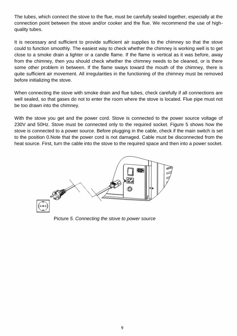
7.1 STARTING THE STOVE
Before starting the stove, display will show „OFF“. In order to start the stove press P3 for several
seconds. When stove is started, display will show „ON“ which is presented on picture 8. Led
indicator ON/OFF will swich on..
In this phase, lighter/igniter is getting warmer (which is indicated with led lamp on display) and
exhaust fan starts to work.
Exhaust fan will be operational always when stove is ON but also it will continue to work after the
stove is OFF.
Picture 8. Appereance on display: „ON“
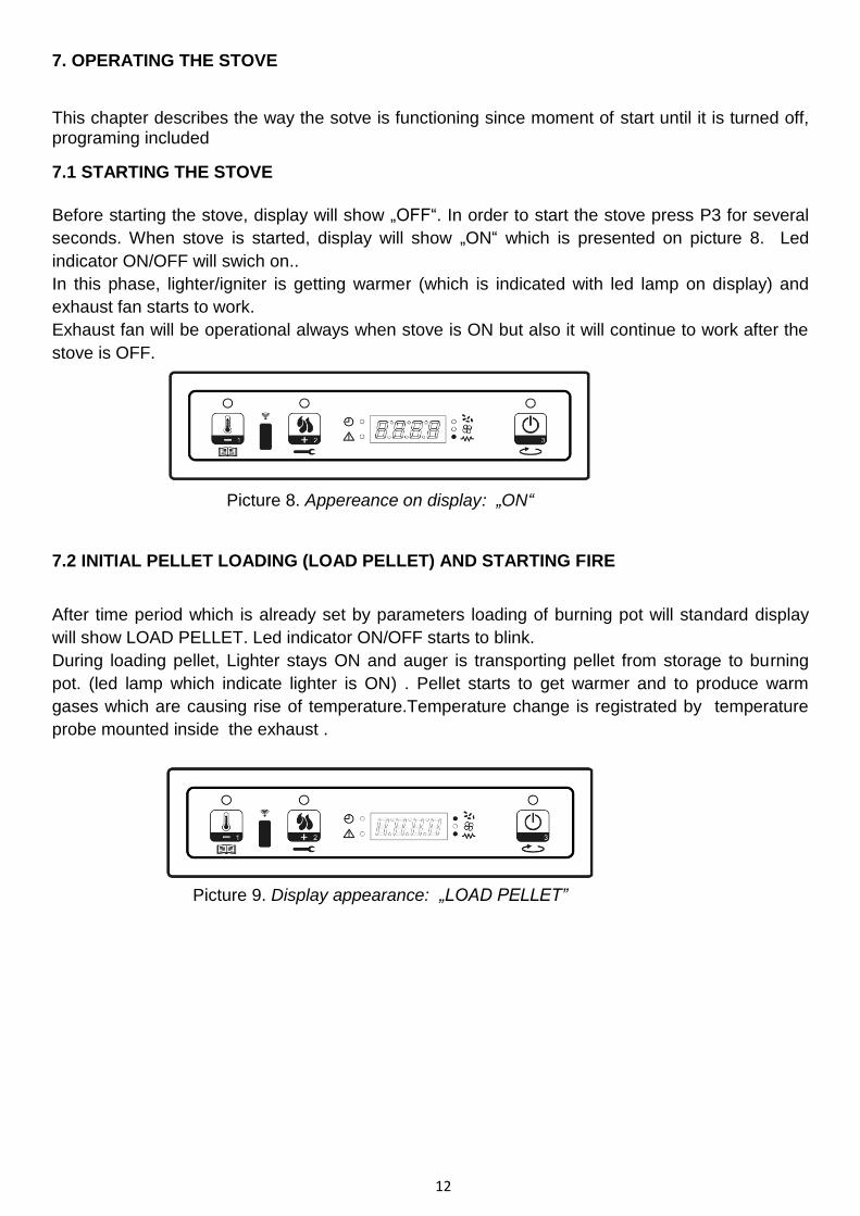
7.2 INITIAL PELLET LOADING (LOAD PELLET) AND STARTING FIRE
After time period which is already set by parameters loading of burning pot will standard display
will show LOAD PELLET. Led indicator ON/OFF starts to blink.
During loading pellet, Lighter stays ON and auger is transporting pellet from storage to burning
pot. (led lamp which indicate lighter is ON) . Pellet starts to get warmer and to produce warm
gases which are causing rise of temperature.Temperature change is registrated by temperature
probe mounted inside the exhaust .
Picture 9. Display appearance: „LOAD PELLET”

13
7.3 STARTING FIRE
When temperature of gases in firebox achieves temperature set by parameters, system is entering
Starting fire mode. Display shows FLAME LIGHT and led indicator “ON/OF” blinks.
Picture 10. Display appearance: „FLAME LIGHT“
In this phase, temperature should remain stabile for period which is already set by parameters.
7.4 OPERATION MODE
Stove is entering Operation mode after the temperature of exhaust gasess achieve value which is
bigger than temperature set by parameters.
Display will show „FLAME ON“, led indicator “ON/OFF” is turned on constantly.
Press P2 to set power. Room temperature is set by pressing P1.
Exhaust gases temperature continue to grow and when it reach next set point (determined by
parmaeters), convection fan starts to blow (convection fan indicator on display will turn ON).
Picture 11. Display apperance „FLAME ON”
After time period set by Paramter, system is cleaning the burning pot automatically and display
shows, „CLEANING FIRE POT. During cleaning, auger is working slowly (led indicator is turned
ON), and exhaust fan speed is increasing (picture 12.).
After the cleaning, stove in entering back in to the Operation mode.
Picture 12. Display apperance „CLEANING FIRE POT”
RITTIUM 3 (3P) offers 5 power modes, P1 (min.) - P5 (max.).
Depending on power mode, auger is set to work in time periods (led lamp is turning on and off).
Lighter remain turned of (Led indiocator is turned off).

14
7.5 THERMAL OUTPUT SETTING
During operating stove, it is possible to tune Thermal output by pressing P2 (led indicator of
thermal power is ON). To increase thermal output, press P2 again. To decrease, press P1.
Demanded thermal output will be presented on display (picture 13). To exit settings, don’t use
control panel for 5 seconds or press P3.
Picture 13.Example of display appearance-Power 3
7.6 CHANGE OF ROOM TEMPERATURE
To change room temperature press P1. Display will show current temperature.by pressing P1 and
P2 it is possible to increase and decrase temperature.
After 5 seconds or by pressing P3 control unit is accepting new set points and display is returning
to previous apperance. Check picture 14.
Picture 14. Display appearance with set temperature
7.7 ACHIEVING OF SET ROOM TEMPERATURE
After the demanded temperature is achieved, thermal output will be reduced to minimum – mode
P1. Display will show „MODU” (Modulation), as shows picture 15.
If room temperature falls below set temperature, stove will enter back in to working mode with
previously determined thermal output.
Picture 15.

15
7.8 STAND - BY MODE
STAND BY option should be primarily activated in the Menu. It enables the stove to turn OFF
when all set points are reached or surpassed for aprox. 2 minutes.
Also, if room temperature is overpassing the set point for more than 2ºC, this mode starts in several minutes. Display will show „GO-STAND BY“(Picture 16).
Picture 16.
Next, display will show „ Wait cooling “. In this mode, auger will be off (LED indicator is off). Stove will get cooler and convection fan will turn off after the set point of exhaust gases temperature
(60ºC) is reached. Led indicator ON/OFF is blinking as shown in picture 17.
Picture 17. Display appearance: „ WAIT COOLING“
Temperature of exhaust gases continue to fall and after reaching set point of 45ºC which is determined by parameters, stove in entering STAND-BY mode. Display shows „STOP ECO TEMP GOOD". Auger is OFF, convection fan and exhaust fan are OFF. Check the following picture 18.
Picture 18.
If room temperature decrease and fall below set point for more than 2ºC, stove will turn ON but
only if time interval of 5 minutes since operating and turning OFF the stove is elapsed.
7.9 TURNING OFF THE STOVE
To turn OFF the stove, press P3 and wait for display to show „CLEANING FINAL”. Auger will turn OFF but convection fan and exhaust fan will continue to work. Led indicator ON/OFF will blink as shown on picture 19.

16
Picture 19. Display appearance: „CLEANING FINAL“
Convection fan will remain on until temperature of exhaust gases is low as it is determined by
technical parameter. Exhaust fan is last to turn OFF. Display will show „OFF“.
Picture 20. Display appearance: „OFF“
8. MENU
Enter MENU by pressing P1.
MENU is is organized in different levels which are enabeling approach to different settings and
programs.
8.1 MENU STRUCTURE
Structure of the menu is presented in table below having in mind options which are available to
final customer.
Structure of the menu:
Level 1 Level 2 Level 3 Set point
M1
CLOCK SETTING
01 – day of the week M - T - W - T - F - S - S
02 - hour 0-23
03 - minute 0-59
04 - day 1-31
05 - month 1-12
06 - year 00-99
M2 PROGRAMING
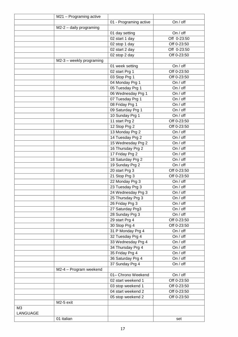
17
M21 – Programing active
01 - Programing active On / off
M2-2 – daily programing
01 day setting On / off
02 start 1 day Off 0-23:50
02 stop 1 day Off 0-23:50
02 start 2 day Off 0-23:50
02 stop 2 day Off 0-23:50
M2-3 – weekly programing
01 week setting On / off
02 start Prg 1 Off 0-23:50
03 Stop Prg 1 Off 0-23:50
04 Monday Prg 1 On / off
05 Tuesday Prg 1 On / off
06 Wednesday Prg 1 On / off
07 Tuesday Prg 1 On / off
08 Friday Prg 1 On / off
09 Saturday Prg 1 On / off
10 Sunday Prg 1 On / off
11 start Prg 2 Off 0-23:50
12 Stop Prg 2 Off 0-23:50
13 Monday Prg 2 On / off
14 Tuesday Prg 2 On / off
15 Wednesday Prg 2 On / off
16 Thursday Prg 2 On / off
17 Friday Prg 2 On / off
18 Saturday Prg 2 On / off
19 Sunday Prg 2 On / off
20 start Prg 3 Off 0-23:50
21 Stop Prg 3 Off 0-23:50
22 Monday Prg 3 On / off
23 Tuesday Prg 3 On / off
24 Wednesday Prg 3 On / off
25 Thursday Prg 3 On / off
26 Friday Prg 3 On / off
27 Saturday Prg3 On / off
28 Sunday Prg 3 On / off
29 start Prg 4 Off 0-23:50
30 Stop Prg 4 Off 0-23:50
31 P Monday Prg 4 On / off
32 Tuesday Prg 4 On / off
33 Wednesday Prg 4 On / off
34 Thursday Prg 4 On / off
35 Friday Prg 4 On / off
36 Saturday Prg 4 On / off
37 Sunday Prg 4 On / off
M2-4 – Program weekend
01– Chrono Weekend On / off
02 start weekend 1 Off 0-23:50
03 stop weekend 1 Off 0-23:50
04 start weekend 2 Off 0-23:50
05 stop weekend 2 Off 0-23:50
M2-5 exit
M3
LANGUAGE
01 italian set

18
02 english Set
03 french Set
04 german/spanish set
M4
STAND BY
01 stand by On / off
M5
SOUND ALERT
01 sound alert On / off
M6
INITIAL LOADING
01 initial loading 90"
М7
status stove
01 status stove
01-Status auger Info
02-T minutes Iinfo
03-Status thermostat Info
04-Status fumes Info
05-Status Exhaust fan info
M8 Technical
calibration
01- Enter with
password
set
M9 01-exit set
8.2 TIME SETTING
Time and date setting: Thanks to battery, internal clock is autonomus approx.5 years.
To enter general programing manu press P1 for 2 seconds. By pressing P1 (decrease) or P2
(increase), picj the M1 and display will show „M1 TIME SETTING“ (picture 21.)
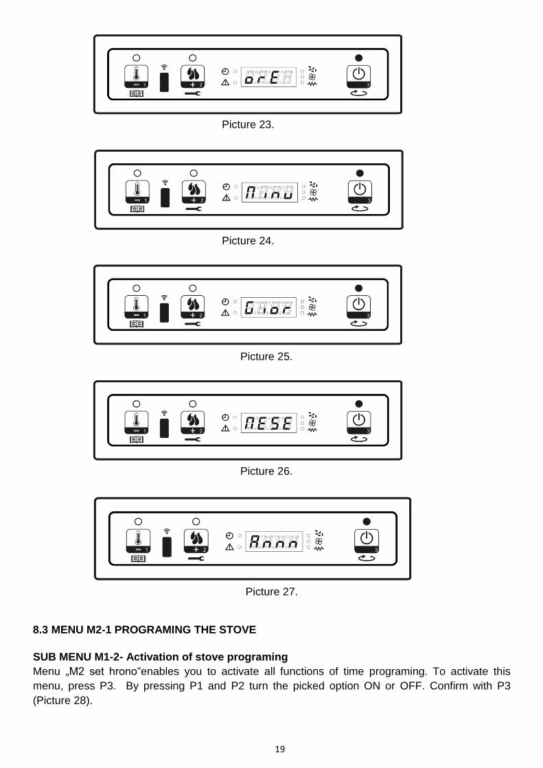
Pick the day and press P3 to confirm (picture 22.). After that set the hour (picture 23), minute
(picture 24), day (picture 25), month (picture 26) and year (picture 27). Press P1 to reduce a P2 to
increase. Press P3 to confirm set point.
Picture 21.
Picture 22.
19
Picture 23.
Picture 24.
Picture 25.
Picture 26.
Picture 27.
8.3 MENU M2-1 PROGRAMING THE STOVE
SUB MENU M1-2- Activation of stove programing
Menu „M2 set hrono“enables you to activate all functions of time programing. To activate this
menu, press P3. By pressing P1 and P2 turn the picked option ON or OFF. Confirm with P3
(Picture 28).

20
Picture 28.
SUB MENU M2-2- Daily program
Pick the M2-2 – daily program with pressing P3 to get different options of daily programing.
Picture 29.
You can set up two working groups, the first with START STOP1 Day 1 and the second with
START2 Day and STOP2 Day, delimited by the times set according to the following table. Option
OFF indicates to clock to ignore given command. To change set point, use the P1 and P2. Press
P3 to confirm.
DAILY PROGRAM
SUB MENU OPTION EXPLANATION PossibleSetting points
M2-2-01 Daily programing Activate 0n/off
M2-2-02 Start 1 Day Time of activation OFF-0-23:50
M2-2-03 Stop 1 Day Time of deactivation OFF-0-23:50
M2-2-04 Start 2 Day Time of activation OFF-0-23:50
M2-2-05 Stop Day Time of deactivation OFF-0-23:50
SUB MENU M2-3-Weekly program
Menu M2-3-Weekly program enable to activate and deactivate and to set weekly program of the
stove. Weekly program has 4 independent programs. Sett OFF in appropriate field in order to
make clock to ignore appropriate command.
Belowe listed tables tables describe th way of weekly program functioning.
To enter the advanced version, to confirm set parameters and to exit program, press P3.
SUB MENU OPTION EXPLANATION Possible setting points
M2-3-01 Weekly program Activate weekly
programing
On/off
PROGRAM 1
SUB MENU OPTION EXPLANATION Possible seting points
M2-3-02 Start Prg 1 Activation period OFF-0-23:50

21
M2-3-03 Stop Prg 1 Deactivation period OFF-0-23:50
M2-3-04 Monday Prg 1
DA
YS
OF
TH
E W
EE
K
0n/off
M2-3-05 Tuesday Prg 1 0n/off
M2-3-06 Wednesday Prg 1 0n/off
M2-3-07 Thursday Prg 1 0n/off
M2-3-08 Friday Prg 1 0n/off
M2-3-09 Saturday Prg 1 0n/off
M2-3-10 Sanday Prg 1 0n/off
Above mentioned options of the MENU with their explanations are same in case of Program 2, 3
and 4 (starting with M2-3-11 up to M2-3-37).
SUB MENU M2-4 – WEEKEND PROGRAM
This Menu enable seting programs for the days of weekend (days 6 and 7).
Activate the program by pressing P3, option „Weekend settings“and choose the option ON.
By opting Start 1 weekend and Stop 1 weekend, final customer is able to set operating the stove
on Satruday. Operating of stove oon Sunday is enabeled with Start 2 weekend and Stop 2
veekend.
WEEKEND PROGRAM
SUB MENU OPTION EXPLANATION Possible setting points
M2-4-01 Weekend
programing
Weekend
programing
activation
0n/off
M2-4-02 Start 1 Weekend Time to turn ON OFF-0-23:50
M2-4-03 Stop 1 Weekend Time to turn OFF OFF-0-23:50
M2-4-04 Start 2 Weekend Time to turn ON OFF-0-23:50
M2-4-05 Stop 2 Weekend Time to turn OFF OFF-0-23:50
8.4 MENU M3 - LANGUAGE
Pick the language of communication by pressing P1 and P2. Press P3 to confirm. Check Picture
30.
Picture 30.

22
8.5 MENU M4 - STAND BY
This Menu enable activating and deactivating of Stand by. Enter M4 with P3 and opt ON or OFF
by pressing P1 i P2. More explanation of STAND BY mode, you will find in section 7.8.
(Picture 31).
Picture 31.
8.6 MENU M5- SOUND ALERT
This Menu enables activating of Sound alert in case of malfunction. Turning on and off is regulated
with buttons P1 i P2. Press P3 to confirm.
Picture 32.
8.7 MENU M6- INITIAL PELLET LOADING
This option is available only when stove is turned OFF. It enable loading of pellet by auger during
initilalizing stove after the storage was left empty.
After opting M6, display will show „PRESS PLUS“(Picture 33). Press P2 to increase set point.
Exhaust fan will start to work in maximum speed, auger will start (led indicator of auger is ON),and
they continue with work until time on display elapse (Picture34) or until operation is stopped by
pressing P3.
Picture 33.
23
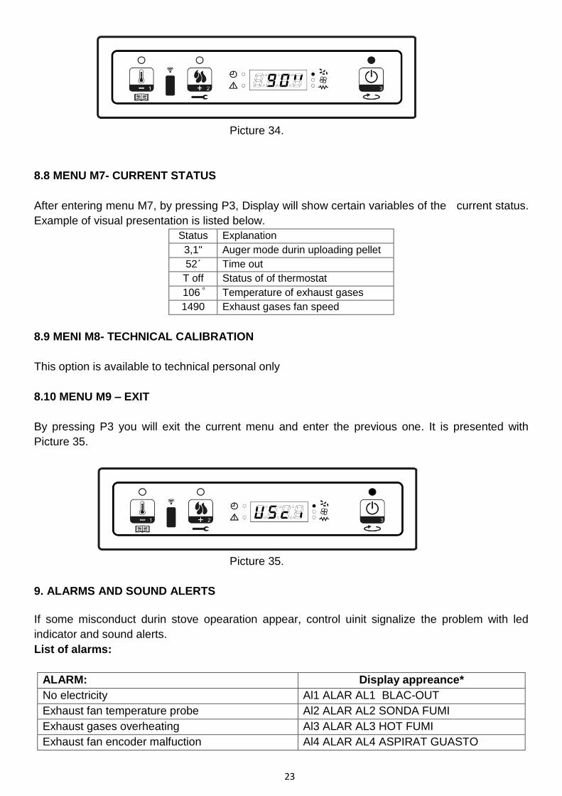
Picture 34.
8.8 MENU M7- CURRENT STATUS
After entering menu M7, by pressing P3, Display will show certain variables of the current status.
Example of visual presentation is listed below.
Status Explanation
3,1" Auger mode durin uploading pellet
52΄ Time out
T off Status of of thermostat
106 ͦ Temperature of exhaust gases
1490 Exhaust gases fan speed
8.9 MENI M8- TECHNICAL CALIBRATION
This option is available to technical personal only
8.10 MENU M9 – EXIT
By pressing P3 you will exit the current menu and enter the previous one. It is presented with
Picture 35.
Picture 35.
9. ALARMS AND SOUND ALERTS
If some misconduct durin stove opearation appear, control uinit signalize the problem with led
indicator and sound alerts.
List of alarms:
ALARM: Display appreance*
No electricity Al1 ALAR AL1 BLAC-OUT
Exhaust fan temperature probe Al2 ALAR AL2 SONDA FUMI
Exhaust gases overheating Al3 ALAR AL3 HOT FUMI
Exhaust fan encoder malfuction Al4 ALAR AL4 ASPIRAT GUASTO

24
Stove did not started Al5 ALAR AL5 MANCATA ACCENS
Lack of pellet fuel Al6 ALAR AL6 MANCANO PELLET
Overheating safety thermostat Al7 ALAR AL7 SICUREC TERMICA
Lack of pressure Al8 ALAR AL8 MANCA DEPRESS
*-Display appereance is presented in Italian language (basic version).
Each above mentiond alarm is followed by shutting the stove OFF.
Alarm is turning on after time period which is set by Parameter PR11 (exept alarm for no
electricity) and it can be reset with pressing P3. Each time alarm turn on for safety reasons, stove
will shut down. In case that sound alert option is activated, sound alert will turn on. Even in case
that Alarm is not noticed and stopped by customer, stove will stop working and display will present
information related kind if malfunction.
NO ELECTRICITY
Lack of electricity for several reasons is possible inconvenience in everyday life.
During restarting the stove, if lack of electricity lasted shorter period that it is determined by
Parameters, stove will continue to work normally. If opposite, alarm will turn on. Display will show
„A1 alar al 1 Blac-out“ and stove will shut down by it self.
EXHAUST GASES TEMPERATURE PROBE
This alarm will turn ON if exhaust gases probe stop functioning. Led indicator and sound alert will
turn ON (if active). Display will show „Al 2 alar al 2 “ and stove will shut down.
OVERHEATING OF EXHAUST GASES
This alarm will turn ON if exhaust fan probe indicate higher temperature than usual. Display will
show „Al 3 alar al 3 “ and stove will shut down.
ENCODER OF EXHAUST FAN MALFUNCTION
Alarm will turn on in case of exhaust fan malfunction.
Display will show „Al 4 alar al 4“.
MALNUCTION DURING START
This alarm will turn ON in case that stove is not starting. It Pappens if temperature of exhaust
gases does not reach set point according to Parameters. Display will show „Al 5 alar al 5 “ and
stove will enter Alarm mode.
LACK OF PELLET
This alarm will turn ON in case that temperature of exhaust gases does not reach set points
according Parameters.Display will show „Al 6 alar al 6 “and stove will enter Alarm mode.
OVERHATING OF SAFETY THERMOSTAT

25
Alarm will turn ON in case that safety thermostat indicates temperature higher than temperature which is neaded to start working. Thermostat will stop the auger . Alarm led indicator is ON same as Alarm and display shows „Al 7 alar al 7 “ . Stove will shut down.
LACK OF PRESSURE
In case that pressure probe indicates lower pressure than it is needed to ignite the stove, presostat will stop the auger. Alarm led indicator is ON same as Alarm and display shows„Al8 alar al 8 “. Stove will shut down.
10. CLEANING AND MAINTAINANCE
During the daily and weekly cleaning turn off the stove at the main switch, set the switch in the
position 0. Before stove is being completely cleaned, it should be disconected from the power
source. Stove should be cleaned at least 30 minutes after finishing its work, in order to avoid burns
in contact with hot parts of the stove.
When cleaning with a damp cloth or water, be careful that water does not reach the electrical parts
of the stove. If it happens, by chance, do not to turn on the stove and call the authorized service.
When cleaning the stove, avoid strong detergents and abrasives, and all products containing solvents, alcohols, acids, or any solvent.
Glass is being cleaned with a dry cloth, if there are a traces of soot, the glass can be cleaned with a damp cloth, but then wiped again with a dry cloth. Painted and plastic parts clean with a slightly damp cloth, and use only a mild detergent diluted with water.
Daily cleaning Includes a glass cleaning and cleaning of glass cups where the burning rocesstakes place. The ash
remained in the cup put away from flammable elements, in order to prevent possible remains of some
incandescent pellets. Make sure that all the holes in the cup are well cleaned. You can also clean and
ashes from the firebox. To clean the ashes from the firebox, you can use the vacuum cleaner.
Weekly cleaning In addition to daily cleaning, it is necessary to empty the ash pan at least once a week if you’re using more pellets.
Monthly cleaning Stove has to be cleaned completely once in a month and at the end of the heating season. In addition to instructions for weekly and daily cleaning it’s necessary to open the stove on provided
spots and clean it accurately. During the monthly cleaning, act by a following order of removing parts in order 1-2-3-4-5-6 (Picture 36).
When getting all parts together do it in a reverse order. Soot and fly ash formation need to be removed.
Remains of combustion will contain small particles of fly ash. The fling ash will collected in the exhaust venting and influence the flow of gases. Incomplete combustion which occurs during start-up and shut- down on incorrect operation of the room
heater, will lead to some soot formation, which will be reside in the venting system and exchanger. The venting system should be inspected at least once a year and clean if necessary.

26
Picture 36. Schedule of disassembling because of monthly cleaning
27
11. WARRANTY
Stove will work well only if you follow the given instructions. TIM SISTEM is obligated to
provide spare parts and eliminate interference with the stove that are covered by this warranty
within the time limit not exceeding 45 days from the date of defect report . If the defect is not
corrected within 45 days, you have the right to a substitution for a new product. The warranty is valid from the date of purchase, as evidenced by duly completed guarantee certificate, and the shop’s receipt.
The warranty for this product is 24 months. TIM SISTEM is obliged to provide spare parts in due time after the stove is no longer produced.
This warranty does not cover damage caused by:
• inadequate use of stoves; • violating the instructions given in this manual; • mechanical damage incurred due to inadequate storage and transport; • due to mechanical damage caused by kicking, tumbling; • due to inadequate exposure to rain, snow etc.; • due to chemical damage caused by exposure to inflammatory agents such as • oil and oil products, alcohol, solvents, paints; • due to natural disasters such as lightning, floods, fire;
The parts subjected to wear, such as braiding (glass), gaskets, rubber parts (rubber feet, spacers), are not covered by this warranty.
All malfunctions report in written or orally by telephone, on the address listed in Warranty
certificate.

28
TIM SISTEM d.o.o.
Prva industrijska 9
22 330 Nova Pazova, Serbia
tel/fax: +381 22 32 80 76
e-mail: [email protected]
www.timsistem.rs