Ritmo basic 160
95
Rev.: 0 16/10/2012 MU000838 واﻟﺼﻴﺎﻧﺔ اﻻﺳﺘﺨﺪام آﺘﻴﺐUSE AND MAINTENANCE HANDBOOK BASIC 355 V0 BASIC 315 V1 BASIC 250 V1 BASIC 200 V0 BASIC 160 V1
-
Upload
alwasail-company -
Category
Documents
-
view
397 -
download
22
description
Basic 160 is able to weld fittings such as Elbows, tees, Y-branches and flanges necks without any additional equipment by simply fixing the clamps drag bar.
Transcript of Ritmo basic 160

Rev.: 0 16/10/2012 MU000838
آتيب االستخدام والصيانةUSE AND MAINTENANCE HANDBOOK
BASIC 355 V0
BASIC 315 V1
BASIC 250 V1
BASIC 200 V0
BASIC 160 V1

S.p.A.
Via A. Volta, 7 – (Z.I.) 35037 Teolo (PD)
ITALY إيطاليا
Tel. +39.049/9901888هاتف Fax +39.049/9901993فاآس
I Ritmo S.p.A. è libera di apportare modifiche senza preavviso alle caratteristiche della macchina descritta in questo manuale e alle informazioni qui contenute. È vietata la riproduzione, anche parziale e sotto qualsiasi forma, di questo documento.
GB Ritmo S.p.A. is free to modify the contents of this handbook, as well as the features of the machine described herein, at any time, without notice. All rights reserved. It is strictly prohibited to reproduce this document or part of it in any form whatsoever.
F L’entreprise Ritmo S.p A. Se réserve le droit d’apporter, sans préavis, toutes les modifications qu’elle désirera aux caractéristiques de la machine décrite dans ce manuel ainsi qu’aux informations qu’il contient. La reproduction de ce document, même partielle, sous n’importe quelle forme, est strictement interdite.
E Ritmo S.p.A. se reserva el derecho de hacer modificaciones sin previo aviso a las características de la máquina descrita en este manual y a las informaciones en él incluidas. Está terminantemente prohibida toda reproducción de este documento, incluso parcial o de cualquier otra
P A Ritmo S.p.A. pode efectuar sem pré-aviso quaisquer modificações às características da máquina descrita no presente manual, bem como às informações nele inseridas. A cópia total ou parcial deste documento è severamente proibida, sob qualquer forma.
D Die hier angegebenen Daten sind öhne Gewähr und Ritmo S.p.A. behält sich Änderungen ohne Vorankündigung vor. Die Vervielfertigung, auch auszugsweise, dieses Dokumentes ist verboten.
Rus Ritmo S.p.A имеет право вносить изменения в аппарат, описанный в данной инструкции и в информацию о нём без предварительного уведомления. Все права защищены. Данный документ и любые его части воспроизводить запрещено.

INDEX الفهرس
مقدمة 1./1 مقدمة للمنتج والمواصفات. 1 1./2 معايير اللحام العامة. 2
1./2 التفريغ، المناولة والتخزين/النقل، التحميل 1./2 الخدوش والتحزيزات
1./2 قبل اللحام 2./2 اإلعداد
3./2 دورات اللحام 4./2 المراقبة بالعين المجردة: خرز اللحام
1./3 وصف القطع. 3 1./3 لشاسيها
1./3 المسواة 2./3 لوح التسخين
2./3 المسواة/دعامة لوح التسخين 3./3 علبة التروس الهيدروليكية
3./3 المؤقت 4./3 المعدة القياسية
1./4 تعليمات التشغيل. 4 1./4 الوصالت الهيدروليكية
1./4 الوصالت الكهربية DIGITAL DRAGON 4/.3المنظم الحراري
4./4 خال الخافضاتإد 5./4 3و 2آيفية لحام القامطات رقم 5./4 4و 3آيفية لحام القامطات رقم
6./4 التسوية 7./4 دورة اللحام بالضغط البسيط
10./4 دورة اللحام بالضغط المزدوج 1./5 الصيانة. 5 1./6 تحري األعطال وإصالحها. 6 1./7 احتياطات السالمة. 7 1./8 العمل نظافة مكان. 8 1./9 معلمات اللحام. 9
1./9 الترآيبات/خصائص المواسير UNI 10520: PE 80 (MRS 8( 9/.2آيفية حساب معلمات اللحام وفًقا لـ UNI 10967: PE 100 (MRS 10( 9/.3آيفية حساب معلمات اللحام وفًقا لـ DVS 2207-1: HDPE 9/.5آيفية حساب معلمات اللحام وفًقا لـ DVS 220711-: PP 9/.7آيفية حساب معلمات اللحام وفًقا لـ
)PE 80 (UNI 10520تقرير اللحام )PE 100 (UNI 10967تقرير اللحام )HDPE (DVS 2207-1تقرير اللحام )PP (DVS 2207-11تقرير اللحام
Introduction 1. Product Introduction and Specifications 1./1 2. Welding General Criteria 2./1
Transport, loading/unloading, handling and storage 2./1 Scratches and notches 2./1 Before welding 2./1 Set up 2./2 Welding cycles 2./3 Welding bead: naked eye observation 2./4
3. Parts Description 3./1 Chassis 3./1 Facer 3./1 Heating plate 3./2 Facer/heating plate support 3./2 Hydraulic gearcase 3./3 Timer 3./3 Standard equipment 3./4

INDEX الفهرس 4. Operating Instructions 4./1
Hydraulic connections 4./1 Electrical connections 4./1 Thermoregulator DIGITAL DRAGON 4./3 Insertion of reductions 4./4 How to weld between clamps number 2 and 3 4./5 How to weld between clamps number 3 and 4 4./5 Facing 4./6 Simple Pressure welding cycle 4./7 Dual Pressure welding cycle 4./10
5. Maintenance 5./1 6. Trouble Shooting 6./1 7. Safety Precautions 7./1 8. Workplace Hygiene 8./1 9. Welding Parameters 9./1
Pipe/fitting features 9./1 How to calculate the welding parameters according to UNI 10520: PE 80 (MRS 8) 9./2 How to calculate the welding parameters according to UNI 10967: PE 100 (MRS 10) 9./3 How to calculate the welding parameters according to DVS 2207-1: HDPE 9./5 How to calculate the welding parameters according to DVS 2207-11: PP 9./7
Welding Report PE 80 (UNI 10520) Welding Report PE 100 (UNI 10967) Welding Report HDPE (DVS 2207-1) Welding Report PP (DVS 2207-11)

INTRODUCTION مقدمة
عزيزنا العميل،
. Ritmoنشكرك على اختيار جهاز
آما ستجد في هذا الكتيب جميع . للجهاز، وآيفية تحقيق أقصى استفادة منها األساسيةسيوضح لك هذا الكتيب جميع الخصائص ءته بالكامل قبل البدء وبالتالي نحن نوصي بقرا. المعلومات واالقتراحات المطلوبة الستخدام الجهاز بطريقة صحيحة وآمنة واحترافية
. أو للمستخدمين الجدد/آما أننا نوصي باالحتفاظ به للرجوع إليه في المستقبل و. في استخدام الجهاز
.يرجى التذآر أن هذا الجهاز احترافي، ويجب أن يقتصر على األفراد المهرة والمعتمدين
متأآدون من رضائكم التام،
Dear Customer, Thank you for having chosen a Ritmo machine. This handbook will show you all your new BASIC machine features, and how to get the most of them. In this book you will also find all the information and suggestions needed to use the machine in a proper, safe and professional manner. We therefore recommend its complete reading before starting using the machine. We also recommend to keep it for future consultations and/or new users. Please remember that this machine is a professional device; its use must be limited to skilled and certified personnel. Certain of your complete satisfaction,
Best regards, خالص التحيات

1. TECHNICAL FEATURES الخصائص الفنية
1./1
مقدمة
BASIC هي سلسلة من ماآينات اللحام التناآبي داخل الموقع للمواسير والترآيبات المصنوعة من البوليثيلين)PE ( والبولي بروبيلين)PP ( والمواد األخرى التي .تلدن بالحرارة المخصصة لنقل الغاز القابل لالشتعال والمياه والسوائل األخرى التي تكون تحت ضغط عاٍل
.باستخدام طريقة الضغط المزدوج PE 100بإمكانها BASICاآينات جميع م .ونحن نذآرك بأن استخدام الماآينات المماثلة يكون مقصوًرا على األفراد المهرة والمعتمدين، وفًقا للقوانين واللوائح المستخدمة
INTRODUCTION
BASIC is a line of on-site butt welding machines for pipes and fittings in Polyethylene (PE), Polypropylene (PP), and other thermoplastic materials intended for the transport of combustible gas, water, and other fluids under high pressure. All BASIC machines can weld PE 100 with the Dual Pressure method. We remind you that the use of such machines is limited to authorized skilled and certified personnel, in accordance with the Legislation and Regulations in force.
SPECIFICATIONS المواصفات
BASIC 160 V1 BASIC 200 V0 BASIC 250 V1 BASIC 315 V1 BASIC 355 V0 الخصائص220V 220V 220V 220V 220V
355÷125 ∅ 315÷90 ∅ 250÷75 ∅ 200÷63 ∅ 160÷40 ∅ ]ملم [ مدى القطر
ي تلدن بالحرارةوالمواد األخرى الت PPو )PE 100 (MRS 10و) HDPE: PE 80 (MRS 8 مواد قابلة للحام
)40+إلى 0من : PE 100( 40+إلى 5-من ]درجة مئوية [ نطاق درجة الحرارة المحيطة
هرتز 60فولط تيار متناوب 220 إمداد الطاقة
5750 4420 3420 3220 2220 ]وات [ الحد األقصى للطاقة الممتصة
موصل الحماية: 1 فئة العزل
Leq=79.2 ) ]يرأمب(ديسبل [ مستوى الضوضاء
155(آيلوجرام 70 ]آلجم[الماآينة مع جميع الخصائص -الوزن )رطًال
205(آيلوجرام 93 )أرطال
آيلوجرام 124 )رطًال 273.3(
366(آيلوجرام 166 - )رطل
FEATURES BASIC 160 V1 BASIC 200 V0 BASIC 250 V1 BASIC 315 V1 BASIC 355 V0 220V 220V 220V 220V 220V
Diameters range [ mm ] ∅ 40÷160 ∅ 63÷200 ∅ 75÷250 ∅ 90÷315 ∅ 125÷355
Weldable materials HDPE: PE 80 (MRS 8) and PE 100 (MRS 10), PP and other thermoplastics materials
Ambient temperature range [ ° C ] from -5 to +40 (PE 100: from 0 to +40)
Power supply 220VAC 60Hz
Maximum absorbed power [ W ] 2220 3220 3420 4420 5750
Isolation class 1: protection conductor
Noise level [ dB (A) ] Leq=79.2
Weight - machine with all features [kg] 70 Kg (155lb) 93 Kg (205 lb) 124 Kg (273.3 lb) 166 Kg (366 lb) -
الشاسيه
14,130 6,680 5,890 3,156 1,947 ] 2سم[ قسم الدفع اإلجمالي
]ملم [ األبعاد، العرض العمق االرتفاع 606x365x375 ملم
)23.9x14.4x14.8 )بوصة
ملم 420×460×685)27x18.2x16.5 بوصة(
850x470x400 ملم )33.5x18.5x15.7
)بوصة
981x586x520 ملم )38.6x23x20.5 ةبوص(
1077x510x715 ملم )42.4x20x28 بوصة(
46.3(آيلوجرام 21 ]آلجم [ الوزن )رطًلا
86(آيلوجرام 39 )رطًال
138.9(آيلوجرام 63 )رطًال
189.6(آيلوجرام 86 )رطًال
آيلوجرام 100 )رطًال 220.5(
CHASSIS
Overall thrust section [ cm2 ] 1,947 3,156 5,890 6,680 14,130
Dimensions W D H [ mm ] 606x365x375 mm (23.9x14.4x14.8 in)
685×460×420 mm (27x18.2x16.5 in)
850x470x400 mm (33.5x18.5x15.7 in)
981x586x520 mm (38.6x23x20.5 in)
1077x510x715 mm (42.4x20x28 in)
Weight [ kg ] 21 Kg (46.3 lb) 39 Kg (86 lb) 63 Kg (138.9) 86 Kg (189.6 lb) 100 Kg (220.5 lb)
المسواة
900 1050 1050 1050 1050 ]وات [ القدرة االسمية
22 67 73 109 109 ]دورة في الدقيقة [ سرعة الدوران
ملم 280×325×375 ]ملم [ األبعاد، العرض العمق االرتفاع )14.8x12.9x11 بوصة(
- 440x450x380 ملم )17.3x17.7x15 بوصة(
ملم 390×460×600)23.6x18.1x15.3
)ةبوص
931x615x220 ملم )36.6x24.2x8.7
)بوصة
24.2(آيلوجرام 11 )رطًال 19.9(آلجم 9 ]آلجم [ الوزن )رطًال
33.1(آيلوجرام 15 )رطًال
53(آيلوجرام 24 )رطًال
83.8(آيلوجرام 38 )رطًال
لوح التسخين
3750 3000 2000 1800 800 ]وات [ الحد األقصى للطاقة الممتصة

1. TECHNICAL FEATURES الخصائص الفنية
1./2
درجة مئوية 320÷50 ة الحرارة ضبط درج
دقيقة 20 > زمن الوصول إلى درجة حرارة العمل
ملم 50×280×410 ]ملم [ األبعاد، العرض العمق االرتفاع )16.1x11x2 بوصة(
ملم 490×50×470 -)18.5x2x19.3 بوصة(
ملم 600×50×470)18.5x2x23.6 بوصة(
696x175x700 ملم )27.4x6.9x27.6
)بوصة
6.6(آيلوجرام 3 ]آلجم [ ن الوز )أرطال
13.2(آيلوجرام 6 )رطًال
17.6(آيلوجرام 8 )رطًال
28.7(آيلوجرام 13 )رطًال
39.7(آيلوجرام 18 )رطًال
FACER
Nominal power [ W ] 1050 1050 1050 1050 900
Rotation speed [ RPM ] 109 109 73 67 22
Dimensions W D H [ mm ] 375×325×280 mm (14.8x12.9x11 in) - 440x450x380 mm
(17.3x17.7x15 in) 600×460×390 mm (23.6x18.1x15.3 in)
931x615x220 mm (36.6x24.2x8.7 in)
Weight [ kg ] 9 Kg (19.9 lb) 11 Kg (24.2 lb) 15 Kg (33.1 lb) 24 Kg (53 lb) 38 Kg (83.8 lb)
علبة التروس الهيدروليكية
1100 370 ]وات [ قدرة االسمية ال
120 ÷ 0 150 ÷ 0 ]بار [ نطاق الضغط
ISO 3448 68أو 46فئة اللزوجة زيت الهيدروليك TEXACO RANDO HDZ 46، ESSO UNIVIS N 46 SHELL TELLUS T 46: الموصى به
- )بوصة 25.6x9.8x15.7(ملم 650x250x400 ]ملم [ األبعاد، العرض العمق االرتفاع
- )رطًال 64(آيلوجرام 29 ]آلجم [ الوزن
HEATING PLATE
Maximum absorbed power [ W ] 800 1800 2000 3000 3750
Temperature adjustment 50÷320°C Time to reach working the temperature < 20 min.
Dimensions W D H [ mm ] 410×280×50 mm (16.1x11x2 in) - 470×50×490 mm
(18.5x2x19.3 in) 470×50×600 mm (18.5x2x23.6 in)
696x175x700 mm (27.4x6.9x27.6 in)
Weight [ kg ] 3 Kg (6.6 lb) 6 Kg (13.2 lb) 8 Kg (17.6 lb) 13 Kg (28.7 lb) 18 Kg (39.7 lb)
علبة التروس الهيدروليكية
1100 370 ]وات [ القدرة االسمية
120 ÷ 0 150 ÷ 0 ]بار [ نطاق الضغط
ISO 3448 68أو 46فئة اللزوجة زيت الهيدروليك TEXACO RANDO HDZ 46، ESSO UNIVIS N 46 SHELL TELLUS T 46: الموصى به
- )بوصة 25.6x9.8x15.7(ملم 650x250x400 ]ملم [ األبعاد، العرض العمق االرتفاع
- )رطًال 64(آيلوجرام 29 ]آلجم [ الوزن
HYDRAULIC GEARCASE
Nominal power [ W ] 370 1100
Pressure range [ bar ] 0 ÷ 150 0 ÷ 120
Hydraulic oil Viscosity class 46 or 68 ISO 3448 Recommended : TEXACO RANDO HDZ 46, ESSO UNIVIS N 46 SHELL TELLUS T 46
Dimensions W D H [ mm ] 650x250x400 mm (25.6x9.8x15.7 in) -
Weight [ kg ] 29 Kg (64 lb) -
المسواة/دعامة لوح التسخين
]ملم [ األبعاد، العرض العمق االرتفاع 340x440x230 ملم
)1.34x1.73x0.91 )بوصة
365x505x205 ملم )14.4x19.9x8.1
)بوصة-
690x560x290 ملم )2.72x2.20x1.14
)بوصة-
13.2(آيلوجرام 6 ]آلجم [ الوزن )رطًال
16.5(آيلوجرام 7.5 )رطًال
19.9(آيلوجرام 9 )رطًال
30.9(آيلوجرام 14 - )رطًال
FACER/HEATING PLATE SUPPORT
Dimensions W D H [ mm ] 340x440x230 mm (1.34x1.73x0.91 in)
365x505x205 mm (14.4x19.9x8.1 in) - 690x560x290 mm
(2.72x2.20x1.14 in) -
Weight [ kg ] 6 Kg (13.2 lb) 7,5 Kg (16.5 lb) 9 Kg (19.9 lb) 14 Kg (30.9 lb) -
1. TECHNICAL FEATURES الخصائص الفنية
1./3
OPTIONS الخيارات
BASIC 160 V0 BASIC 200 V0 BASIC 250 V1 BASIC 315 V1 BASIC 355 V0
الخافضات
األقطار ]آيلوجرام ) [ القطر /قطع 8( الوزن
∅ 40 10.1(لوجرام آي 4.6
- - - - )أرطال
∅ 50 9.7(آيلوجرام 4.4
- - - - )أرطال
∅ 56 9.5(آيلوجرام 4.3
- - - - )أرطال
∅ 63 9.3(آيلوجرام 4.2
)أرطال 14.5(آيلوجرام 6.6
- - - )رطًال
∅ 75 8.8(آيلوجرام 4.0
)أرطال 14.1(آيلوجرام 6.4
)رطًال 23.3(آيلوجرام 10.6
- - )رطًال
13.2(آيلوجرام 6.0 )رطل 8.1(آيلوجرام 3.7 90 ∅ )رطل
22(آيلوجرام 10.0 )رطًال
22(آيلوجرام 10.0 - )رطًال
12.1(آيلوجرام 5.5 )أرطال 7(آيلوجرام 3.2 110 ∅ )رطل
21.6(آيلوجرام 9.8 )رطل
21.6(آيلوجرام 9.8 - )رطل
∅ 125 5.7(آيلوجرام 2.6
)رطًال 20(آيلوجرام 9.1 )رطل 20(آيلوجرام 9.1 )رطل 20(آيلوجرام 9.1 )رطل 11(آيلوجرام 5.0 )أرطال
∅ 140 4.4(آيلوجرام 2.0
)أرطال 9.9(آيلوجرام 4.5
)أرطال 18.3(آيلوجرام 8.3
)رطل 18.3(آيلوجرام 8.3
)رطل 18.3(آيلوجرام 8.3
)رطل
16.5(آيلوجرام 7.5 )أرطال 8(آيلوجرام 3.6 - 160 ∅ )رطل
16.5(آيلوجرام 7.5 )رطل
16.5(آيلوجرام 7.5 )رطل
5.7(آيلوجرام 2.6 - 180 ∅ )أرطال
13.6(آيلوجرام 6.2 )رطل
13.7(آيلوجرام 6.2 )رطل
13.7(آيلوجرام 6.2 )رطل
10.6(آيلوجرام 4.8 - - 200 ∅ )رطل
10.6(آيلوجرام 4.8 )رطل
10.6(آيلوجرام 4.8 )رطل
)أرطال 7(آيلوجرام 3.1 )أرطال 7(آيلوجرام 3.1 )رطل 7(آيلوجرام 3.1 - - 225 ∅
∅ 250 - - - 21.6(آيلوجرام 9.8
)رطل )بييز 4رئيسي (
)رطل 39(آيلوجرام 17.6 )بييز 4رئيسي (
11.9(آيلوجرام 5.4 - - - 280 ∅ )رطل
22.7(آيلوجرام 10.3 )رطل
41.1(آيلوجرام 6.4 - - - - 315 ∅ )رطل
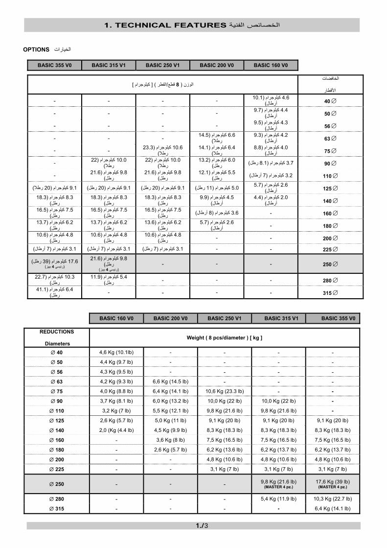
BASIC 160 V0 BASIC 200 V0 BASIC 250 V1 BASIC 315 V1 BASIC 355 V0
REDUCTIONS
Diameters Weight ( 8 pcs/diameter ) [ kg ]
∅ 40 4,6 Kg (10.1lb) - - - - ∅ 50 4,4 Kg (9.7 lb) - - - - ∅ 56 4,3 Kg (9.5 lb) - - - - ∅ 63 4,2 Kg (9.3 lb) 6,6 Kg (14.5 lb) - - - ∅ 75 4,0 Kg (8.8 lb) 6,4 Kg (14.1 lb) 10,6 Kg (23.3 lb) - -
∅ 90 3,7 Kg (8.1 lb) 6,0 Kg (13.2 lb) 10,0 Kg (22 lb) 10,0 Kg (22 lb) -
∅ 110 3,2 Kg (7 lb) 5,5 Kg (12.1 lb) 9,8 Kg (21.6 lb) 9,8 Kg (21.6 lb) -
∅ 125 2,6 Kg (5.7 lb) 5,0 Kg (11 lb) 9,1 Kg (20 lb) 9,1 Kg (20 lb) 9,1 Kg (20 lb)
∅ 140 2,0 (Kg (4.4 lb) 4,5 Kg (9.9 lb) 8,3 Kg (18.3 lb) 8,3 Kg (18.3 lb) 8,3 Kg (18.3 lb)
∅ 160 - 3,6 Kg (8 lb) 7,5 Kg (16.5 lb) 7,5 Kg (16.5 lb) 7,5 Kg (16.5 lb)
∅ 180 - 2,6 Kg (5.7 lb) 6,2 Kg (13.6 lb) 6,2 Kg (13.7 lb) 6,2 Kg (13.7 lb)
∅ 200 - - 4,8 Kg (10.6 lb) 4,8 Kg (10.6 lb) 4,8 Kg (10.6 lb)
∅ 225 - - 3,1 Kg (7 lb) 3,1 Kg (7 lb) 3,1 Kg (7 lb)
∅ 250 - - - 9,8 Kg (21.6 lb) (MASTER 4 pz.)
17,6 Kg (39 lb) (MASTER 4 pz.)
∅ 280 - - - 5,4 Kg (11.9 lb) 10,3 Kg (22.7 lb)
∅ 315 - - - - 6,4 Kg (14.1 lb)

1. TECHNICAL FEATURES الخصائص الفنية
1./4
أداة عنق الشفة
[ األبعاد، العرض العمق االرتفاع - - ]ملم
ملم 490×190×300
)11.8x7.5x19.3 )بوصة
340x182x542 ملم )13.4x7.1x21.3 بوصة(
)رطل 19.9(آيلوجرام 9 )رطل 15.4(آيلوجرام 7 - - ]آلجم [ الوزن
TOOL FOR FLANGE NECKS
Dimensions W D H [mm] - -
300×190×490 mm (11.8x7.5x19.3 in)
340x182x542 mm (13.4x7.1x21.3 in)
Weight [ kg ] - - 7 Kg (15.4 lb) 9 Kg (19.9 lb) ( ⎯ ) NA ال يوجد

2. WELDING GENERAL CRITERIA حام العامةمعايير الل
2./1
. تفريغها ومناولتها وتخزينها، ويجب أن يتم ذلك باستخدام األجهزة الميكانيكية المناسبة/ الترآيبات وتحميلها /يتطلب االنتباه التام عند نقل المواسير
التفريغ النقل والتحميل
مثل األلواح الجانبية(الترآيبات على األسطح الخشنة أو الحادة /تجر المواسير ال. الترآيبات/أو التحزيزات العميقة على المواسير/من المهم تجنب وجود الخدوش و ).بالشاحنة، أدوات العمل، التربة الصخرية، إلخ
The transport, loading / unloading, handling and storage of the pipes/fittings require extreme attention, and must be done by means of suitable mechanical devices.
Transport and Loading Unloading
It is essential to avoid deep scratches and/or notches on the pipes/fittings. Do not drag the pipes/fittings on rough or sharp surfaces (such as truck side-boards, work tools, rocky soil, etc.).
قبل اللحام
:أجهزة القياس
المؤقت المانومتر الترمومتر
.تحقق من وظائفهم
المسواة
.تحقق من وظيفتها
.تأآد من أن الشفرات حادة بدرجة آافية

2. WELDING GENERAL CRITERIA حام العامةمعايير الل
2./2
لوح التسخين
.من سالمة الطالءتحقق
.استخدم ترمومتر رقمًيا للتحقق من أنه تم الوصول إلى درجة الحرارة المعدة
المفصل
.قم بعمل لحام اختباري
BEFORE WELDING
Measuring Instruments:
Timer Manometer Thermometer
Verify their functionality.
Facer
Verify its functionality. Be sure the blades are sharp enough.
Heating plate
Verify the integrity of the coating. Use a digital thermometer to check if the temperature set has indeed been reached.

2. WELDING GENERAL CRITERIA حام العامةمعايير الل
2./3
Joint
Make a test welding.
2. WELDING GENERAL CRITERIA حام العامةمعايير الل
2./4
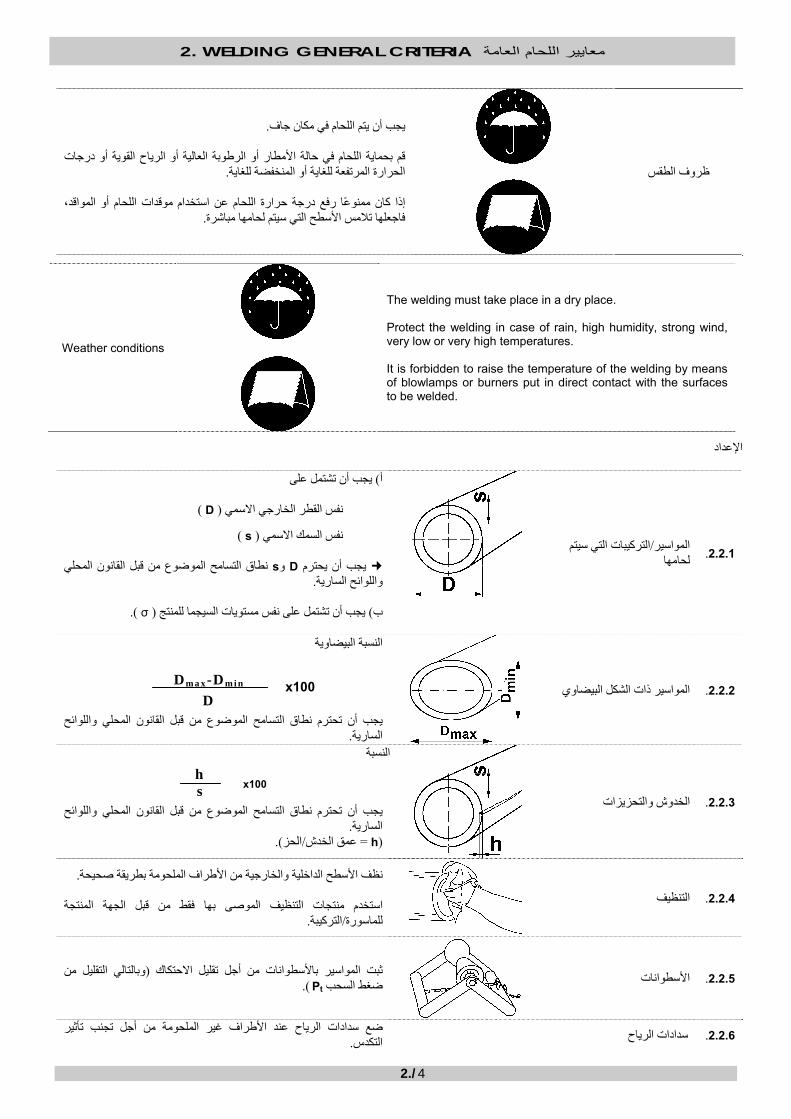
ظروف الطقس
. يجب أن يتم اللحام في مكان جاف
قم بحماية اللحام في حالة األمطار أو الرطوبة العالية أو الرياح القوية أو درجات .الحرارة المرتفعة للغاية أو المنخفضة للغاية
إذا آان ممنوًعا رفع درجة حرارة اللحام عن استخدام موقدات اللحام أو المواقد،
.المس األسطح التي سيتم لحامها مباشرةفاجعلها ت
Weather conditions
The welding must take place in a dry place. Protect the welding in case of rain, high humidity, strong wind, very low or very high temperatures. It is forbidden to raise the temperature of the welding by means of blowlamps or burners put in direct contact with the surfaces to be welded.
اإلعداد
الترآيبات التي سيتم /المواسير .2.2.1 لحامها
يجب أن تشتمل على) أ
) D( نفس القطر الخارجي االسمي
) s( نفس السمك االسمي
اق التسامح الموضوع من قبل القانون المحلي نط sو Dيجب أن يحترم .واللوائح السارية
). σ( يجب أن تشتمل على نفس مستويات السيجما للمنتج )ب
المواسير ذات الشكل البيضاوي .2.2.2
النسبة البيضاوية
واللوائح يجب أن تحترم نطاق التسامح الموضوع من قبل القانون المحلي
. السارية
الخدوش والتحزيزات .2.2.3
النسبة
يجب أن تحترم نطاق التسامح الموضوع من قبل القانون المحلي واللوائح
. السارية)h =الحز/عمق الخدش.(
التنظيف .2.2.4
.حيحةنظف األسطح الداخلية والخارجية من األطراف الملحومة بطريقة ص
استخدم منتجات التنظيف الموصى بها فقط من قبل الجهة المنتجة .الترآيبة/للماسورة
وبالتالي التقليل من (ثبت المواسير باألسطوانات من أجل تقليل االحتكاك األسطوانات .2.2.5 .) Ptضغط السحب
أجل تجنب تأثير ضع سدادات الرياح عند األطراف غير الملحومة من سدادات الرياح .2.2.6 . التكدس
x100 Dm a x-Dm i n D
h s x100

2. WELDING GENERAL CRITERIA حام العامةمعايير الل
2./5
2.2.7.
:أثناء التثبيت تحقق مما يلي
التوازي محاذاة المحور الضوء
يجب مالقاة تلك الحاالت الثالث وفًقا للنطاق الموضوع من قبل القانون المحلي .واللوائح السارية
Ptضغط السحب 2.2.8
.الترآيبة المثبتة في القامطات/ع الماسورةيجب قياسها م
.P5و P1يجب أن تكون دائًما أقل من
SET UP
2.2.1. Pipes/fittings to be welded
a) They must have same nominal outside diameter ( D ) same nominal thickness ( s )
D and s must respect the tolerance range established by the National Legislation and regulations in force. b) They must have the same product sigma ( σ ).
2.2.2. Oval-shaped pipes
The oval-shaped percentage
must respect the tolerance range established by the National Legislation and regulations in force.
2.2.3. Scratches and notches
The percentage
must respect the tolerance range established by the National Legislation and regulations in force. (h = scratch/notch depth).
2.2.4. Cleaning
Accurately clean the internal and external surfaces of the ends to be welded. Use only the cleaning products recommended by the pipe/fitting producer.
2.2.5. Rollers Sustain the pipes with rollers in order to reduce fiction (and therefore reduce the dragging pressure Pt ).
2.2.6. Wind plugs Apply the wind plugs to the ends not being welded in order to avoid a stack effect.
2.2.7.
While fastening check:
Parallelism Axle alignment Light
These three conditions must be met according to the range established by the National Legislation and regulations in force.
2.2.8 Dragging pressure Pt
Must be measured with pipe/fitting fastened in the clamps. Must always be inferior to P1 and P5.
x100 Dm a x-Dm i n D
hs x100

2. WELDING GENERAL CRITERIA حام العامةمعايير الل
2./6
دورات اللحام
:فيما يلي معلمات اللحام التي يجب أن يقوم المشغل بإعدادها ومراقبتها بعد ذلك
الضغوط، درجة حرارة لوح التسخين،
.طول آل مرحلة أبعاد الخرزة،
. ضافة إلى المعلمات الخاصة باألقطار األآثر شيوًعا، باإل9موضحة في الفصل ) وفًقا للمرآب ومعايير اللحام المستخدمة(الصيغ المطلوبة لحساب معلمات اللحام
دورة اللحام بالضغط البسيط
P1: االقتراب والتسخين المسبق
P2: الحد األقصى لضغط التسخين
P5: ضغط اللحام
Pt: علبة التروس تر يجب أن تتم قراءته من قبل المشغل على مانوم -الضغط المطلوب للتغلب على االحتكاك (ضغط السحب (
t1، t2، …، t6: 6، …، 1،2طول المراحل
، وانتظر حتى )P1+Pt(قارب الطرفين اللذين سيتم لحامهما إلى لوح التسخين بضغط مقداره المرحلة األولى االقتراب والتسخين المسبق ).DVS 2207(أو االرتفاع المطلوب ) UNI 10520(يصل الخرز إلى العرض المطلوب
.بالكامل t2للوقت ، الكافية لجعل الطرفين مالمسين للوح التسخين P2قلل الضغط إلى أقصى قيمة . المرحلة الثانية التسخين
.تكرار اللحام يجب بالتأآيدحدث ذلك، فإنه إذا . فصل األطراف الملحومة من لوح التسخين أثناء خفض الضغط أال يتم مطلًقايجب !هام
.الخرز ، بدون إتالف t3فك لوح التسخين خالل أقصى وقت . ة فك لوح التسخينالمرحلة الثالث
. t4، أثناء الوقت ) P5+Pt( اجمع الطرفين مع بعضهما البعض مع زيادة الضغط تدريجًيا إلى القيمة .المرحلة الرابعة الوصول إلى ضغط اللحام . المرحلة امنع التسرب المفرط للمادة الذائبة أثناء القيام بهذه
.بالكامل t5للوقت ) P5+Pt(حافظ على وجود الطرفين مع بعضهما البعض عند الضغط .المرحلة الخامسة اللحام
.بالكامل t6يجب أال يتم فك المفصل وأال يعاني من أي نوع من أنواع الضغط الميكانيكي لوقت .المرحلة السادسة التبريد
. احم المفصل من المطر أو الرياح أو أشعة الشمس المفرطة. غوط الستعجال التبريدال تستخدم المياه أو الهواء المض

2. WELDING GENERAL CRITERIA حام العامةمعايير الل
2./7
WELDING CYCLES
Following are the welding parameters that the operator must set and control afterwards: Heating plate temperature, Pressures, Bead dimension, Length of each phase. The formulas required to calculate the welding parameters (according to the compound and the welding standards being used) are illustrated in Chapter 9, as well as the parameters for the most common diameters. SIMPLE PRESSURE WELDING CYCLE
P1: Approach and pre-heating pressure
P2: Maximum heating pressure
P5: Welding pressure
Pt: Dragging pressure (pressure required to overcome friction - must be read by the operator on the gearcase manometer)
t1, t2, …, t6: Length of Phases 1,2, …, 6
Phase 1 Approach and Pre-heating. Approach both ends to be welded to the heating plate at the (P1+Pt) pressure, and wait until the beads reach the required width (UNI 10520) or height (DVS 2207). Phase 2 Heating. Reduce pressure to P2 maximum value, sufficient to keep the ends in touch with the heating plate for the entire t2 time. IMPORTANT! The ends to be welded MUST NOT detach from the heating plate while the pressure is being reduced. If that happens, the welding must absolutely be repeated. Phase 3 Removal of heating plate. Remove the heating plate within the maximum t3 time, without damaging the beads. Phase 4 Reach of welding pressure. Get both ends together while gradually increasing the pressure up to (P5+Pt) value, during t4 time. Prevent an excessive leakage of melted material while performing this phase. Phase 5 Welding. Keep both ends together at the (P5+Pt ) pressure for the entire t5 time. Phase 6 Cooling. The joint must not be removed or suffer any sort of mechanical strain for the entire t6 time. Do not use water or compressed air to rush cooling. Protect the joint from rain, wind or excessive sunlight.

2. WELDING GENERAL CRITERIA حام العامةمعايير الل
2./8
دورة اللحام بالضغط المزدوج
. لكملم أو يفوق ذ 20بسمك يعادل PE 100تستخدم دورة الضغط المزدوج عند لحام
). الصفحة السابقة(ملم، استخدم دورة الضغط البسيط 20بسمك يقل عن PE 100عند لحام
لما يتعلق بدورة (المراحل األربع األولى متماثلة ).الضغط البسيطة
: تتم مرحلة اللحام في لحظتين. اللحام 5/6المرحلة
. بالكامل t5للوقت ) P5+Pt(غط حافظ على وجود الطرفين مع بعضهما البعض عند الض. 1
. بالكامل t6وحافظ المالمسة للوقت P6قلل الضغط إلى القيمة . 2
. بالكامل t7يجب أال يتم فك المفصل وأال يعاني من أي نوع من أنواع الضغط الميكانيكي لوقت . المرحلة السابعة التبريد
DUAL PRESSURE WELDING CYCLE The Dual Pressure cycle is used when welding PE 100 with thickness equal or superior to 20mm. When welding PE 100 with thickness inferior to 20mm, use the Simple Pressure cycle (previous page).
The first four phases are identical (with respect to the simple pressure cycle).
Phases 5/6 Welding. The welding phase happens in two moments: 1. Keep both ends together at the (P5+Pt) pressure for the entire t5 time. 2. Reduce pressure to P6 value and maintain the contact for the entire t6 time. Phase 7 Cooling. The joint must not be removed or suffer any sort of mechanical strain for the entire t7 time.

2. WELDING GENERAL CRITERIA حام العامةمعايير الل
2./9
:مراقبة المفصل
.دريبيةاتبع دائًما إجراءات العمل المحددة من قبل القانون المحلي واللوائح السارية، إلى جانب اإلجراءات التي تم تعلمها خالل الدورات الت
Control the joint:
Always follow the working procedures established by the National Legislation and regulations in force, as well as those learnt during the training courses.
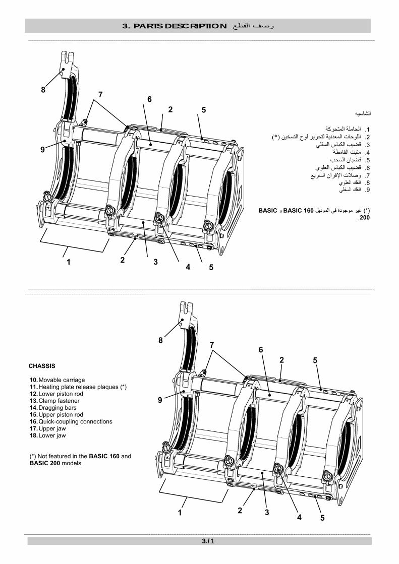
3. PARTS DESCRIPTION وصف القطع
3./1
الشاسيه الحاملة المتحرآة .1 (*)اللوحات المعدنية لتحرير لوح التسخين .2 قضيب الكباس السفلي .3 مثبت القامطة .4 قضبان السحب .5 قضيب الكباس العلوي .6 وصالت اإلقران السريع .7 الفك العلوي .8 الفك السفلي .9
BASICو BASIC 160غير موجودة في الموديل (*)
200.
CHASSIS 10. Movable carriage 11. Heating plate release plaques (*) 12. Lower piston rod 13. Clamp fastener 14. Dragging bars 15. Upper piston rod 16. Quick-coupling connections 17. Upper jaw 18. Lower jaw
(*) Not featured in the BASIC 160 and BASIC 200 models.
7
1 3 2
6
4 5
52
8
9
7
1 3 2
6
4 5
5 2
8
9
3. PARTS DESCRIPTION وصف القطع
3./2
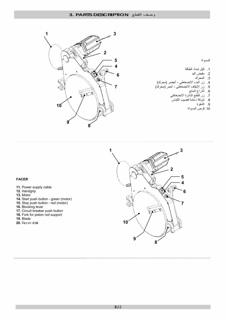
المسواة آبل إمداد الطاقة .1 مقبض اليد .2 المحرك .3 )محرك(أخضر -زر البدء االنضغاطي .4 )محرك(أحمر -زر اإليقاف االنضغاطي .5 الذراع المانع .6 زر قاطع الدائرة االنضغاطي .7 شوآة دعامة قضيب الكباس .8 الشفرة .9
قرص المسواة .10
FACER 11. Power supply cable 12. Handgrip 13. Motor 14. Start push button - green (motor) 15. Stop push button - red (motor) 16. Blocking lever 17. Circuit breaker push button 18. Fork for piston rod support 19. Blade 20. Facer disk
2
3
4 5
6
7
89
10
1
2
3
45
6
7
89
10
1
3. PARTS DESCRIPTION وصف القطع
3./3
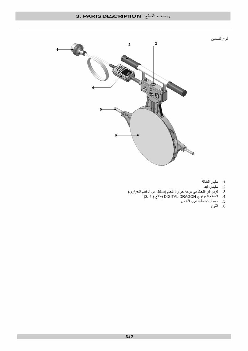
لوح التسخين
اقةمقبس الط .1 مقبض اليد .2 )مستقل عن المنظم الحراري(ترمومتر التحكم في درجة حرارة اللحام .3 )3/.4 §طالع ( DIGITAL DRAGONالمنظم الحراري .4 مسمار دعامة قضيب الكباس .5 اللوح .6
4
1
5
6
32

3. PARTS DESCRIPTION وصف القطع
3./4
HEATING PLATE
7. Power plug 8. Handgrip
9. Welding temperature control thermometer (independent from thermoregulator)
10. Thermoregulator DIGITAL DRAGON (see § 4./3) 11. Pin for piston rod support 12. Plate
المسواة/دعامة لوح التسخين
مقبض اليد .1 مبيت لوح التسخين .2 مبيت المسواة .3
.
1
2
3
4
1
5
6
32

3. PARTS DESCRIPTION وصف القطع
3./5
FACER/HEATING PLATE SUPPORT
4. Handgrip 5. Heating plate housing 6. Facer housing
.
1
2
3

3. PARTS DESCRIPTION وصف القطع
3./6
علبة التروس الهيدروليكية سدادة خزان الزيت .1 صمام تصريف الضغط .2 صمام أقصى مستوى للضغط .3 ذراع الموزع .4 مانومتر ضغط الزيت .5 الخراطيم الهيدروليكية .6 موصالت اإلقران السريع .7
HYDRAULIC GEARCASE 8. Oil tank plug 9. Pressure discharge valve 10. Maximum pressure valve 11. Distributor lever 12. Oil pressure manometer 13. Hydraulic hoses 14. Quick-coupling connectors
4
5 3
2 1
7 6
4
5 3
2 1
7 6

3. PARTS DESCRIPTION وصف القطع
3./7
ؤقتالم )3المؤقت في وضع (الدقائق /مفتاح ضبط الساعات: 1 )2المؤقت ووضع 1 المؤقتفي وضع (الثواني /مفتاح ضبط الدقائق: 2 مفتاح إعادة الضبط: 3 المقاطعة/مفتاح بدء العد التنازلي: 4 ضبط ساعة التنبيه/عرض -العطل مفتاح :5 مفاتيح المؤقت: 6
نيالثوا/إعداد الدقائق: T1وضع الثواني/إعداد الدقائق: T2وضع الدقائق/إعداد الساعات: T3وضع
TIMER 1: Hours/minutes adjustment key (in TIMER 3 mode) 2: Minutes/seconds adjustment key (in TIMER 1 and TIMER 2 modes) 3: Reset key 4: Countdown start/interrupt key 5: Multifunction key – display/adjustment hour-alarm 6: TIMER keys T1 mode: Minutes/seconds setup T2 mode: Minutes/seconds setup T3 mode: Hours/minutes setup
5 6
2 3
1 4
5 6
2 3
1 4

3. PARTS DESCRIPTION وصف القطع
3./8
تعليمات التشغيل
العد التنازلي
).T1، T2، T3( 6اختر الوضع عن طريق الضغط على المفاتيح يمكن مقاطعة العد . لبدء العد التنازلي 4اضغط على المفتاح ). T1، T2(الثواني /أو بالدقائق) T3(الدقائق /لضبط الوقت بالساعات 2أو 1اضغط على المفتاح
لمقاطعة 4اضغط على المفتاح ). ثانية بثانية(ء العد التنازلي، سيقوم المؤقت بقياس وقت التشغيل عند انتها. 4التنازلي وإعادة ضبطه عن طريق الضغط على المفتاح .مرة أخرى الستدعاء الوقت الذي تم ضبطه مسبًقا 4اضغط على المفتاح . العد المتقدم
).الدقائق عن الوميض/ستتوقف ذاآرة الساعات(التنبيه لعرض 5اضغط على المفتاح ). الدقائق/تومض ذاآرة الساعات(لعرض الساعة 5اضغط على المفتاح
:ضبط الساعات
. الدقائق/ستومض الساعات. ثواٍن 3لمدة 5عند عرض الساعة، اضغط على المفتاح .للتأآيد 5اضغط على المفتاح . لضبط الدقائق 2لضبط الساعة، وعلى المفتاح 1اضغط على المفتاح
:ضبط التنبيه
. الدقائق/ستومض الساعات. ثواني 3لمدة 5، اضغط على المفتاح عند عرض التنبيه1اضغط على المفتاح لضبط الساعة، وعلى المفتاح 2 اضغط على المفتاح . لضبط الدقائق 5 .للتأآيد OPERATING INSTRUCTIONS
COUNTDOWN
Choose the mode by pressing keys 6 (T1, T2, T3). Press key 1 or 2 to set time in terms of hours/minutes (T3) or in terms of minutes/seconds (T1,T2). Press key 4 to start countdown. Countdown may be interrupted and re-started at any time by pressing key 4. When countdown is over, timer will measure time run (second by second). Press key 4 to interrupt progressive counting. Press key 4 again to recall the time previously set. Press key 5 to display the hour ( hours/minutes buffer blinks). Press key 5 again to display the alarm ( hours/minutes buffer blinks no more). Hours adjustment: While the hour is displayed, press key 5 for 3 seconds. Hours/minutes will blink. Press key 1 to set the hour, and key 2 to set the minutes. Press key 5 to confirm. Alarm adjustment: While the alarm is displayed, press key 5 for 3 seconds. Hours/minutes will blink. Press key 1 to set the hour, and key 2 to set the minutes. Press key 5 to confirm.

3. PARTS DESCRIPTION وصف القطع
3./9
STANDARD EQUIPMENT المعدة القياسية
حقيبة األدوات .1
للموديل -) يستخدم لتجميع وتفكيك الخافضات(مفتاح ربط ألن .2
BASIC 160 وBASIC 200 فقط.
)يستخدم لربط القامطات(ي مفتاح ربط صندوق .3
آتيب االستخدام والصيانة .4 قائمة قطع الغيار .5
المؤقت .6
7. Tool bag
8. A Allen key wrench (used to assembly and
disassembly the reductions) – only for BASIC 160 and
BASIC 200 models.
9. Socket wrench (used to fasten the clamps)
10. Use and maintenance handbook
11. Parts list
12. Timer
1 3 2
4
6
5
1 32
4
6
5
4. OPERATING INSTRUCTIONS تعليمات التشغيل
4./1
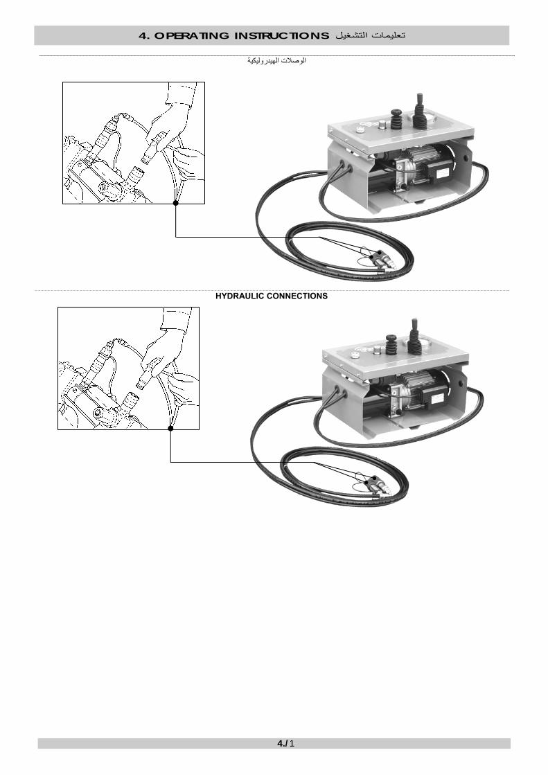
الوصالت الهيدروليكية
HYDRAULIC CONNECTIONS

4. OPERATING INSTRUCTIONS تعليمات التشغيل
4./2
الوصالت الكهربية
التحكم أوًال" مواصفات" )1§ طالع (

4. OPERATING INSTRUCTIONS تعليمات التشغيل
4./3
ELECTRICAL CONNECTIONS
Control “SPECIFICATIONS” first (see § 1.)

4. OPERATING INSTRUCTIONS تعليمات التشغيل
4./4
مجموعة المولد -علبة التروس الهيدروليكية
فولط 220
تأآد من أن مصدر الطاقة يشتمل على .الفولطية المطلوبة
ال تستخدم مصدر طاقة يخضع إلى فرط الحد األقصى المسموح (متكرر في الفولطية
).من الجهد االسمي% 10: +به
استخدم مثبًتا للفولطية
:المسوح بها التمديدات
علبة + لوح التسخين (تشير التمديدات إلى توصيل العديد من المكونات .بمقبس واحد متعدد) المسواة+ التروس الهيدروليكية
BASIC 160 V0 فولط 220
2.5 1,5 ] 2ملم[ قسم الكبل 75 50 ]م [ الحد األقصى لطول الكبل
BASIC 200 V0 فولط 220
2.5 1,5 ] 2ملم[ قسم الكبل 50 25 ]م [ الحد األقصى لطول الكبل
BASIC 250 V1 فولط 220
2,5 1,5 ] 2ملم[ قسم الكبل 50 25 ]م [ الحد األقصى لطول الكبل
BASIC 315 V1 فولط 220
4 2,5 ] 2ملم[ قسم الكبل 50 25 ]م [ صى لطول الكبل الحد األق
BASIC 355 V0 فولط 220
6 4 ] 2ملم[ قسم الكبل 50 25 ]م [ الحد األقصى لطول الكبل

4. OPERATING INSTRUCTIONS تعليمات التشغيل
4./5
Hydraulic gearcase – Generator set
220 V
Be sure that the power source has the requested voltage. Do not use a power source subject to frequent overvoltage (maximum admissible: +10% of the nominal tension). Use a voltage stabilizer.
PERMITTED EXTENSIONS: The extensions refer to the plugging of the various components (heating plate + hydraulic gearcase + facer) to one single multiple socket.
BASIC 160 V0220 V
Cable section [ mm2 ] 1,5 2.5 Cable maximum length [ m ] 50 75 BASIC 200 V0
220 V Cable section [ mm2 ] 1,5 2.5 Cable maximum length [ m ] 25 50 BASIC 250 V1
220 V Cable section [ mm2 ] 1,5 2,5 Cable maximum length [ m ] 25 50 BASIC 315 V1
220 V Cable section [ mm2 ] 2,5 4 Cable maximum length [ m ] 25 50 BASIC 355 V0
220 V Cable section [ mm2 ] 4 6 Cable maximum length [ m ] 25 50
4. OPERATING INSTRUCTIONS تعليمات التشغيل
4./6
بدء التشغيل
START UP
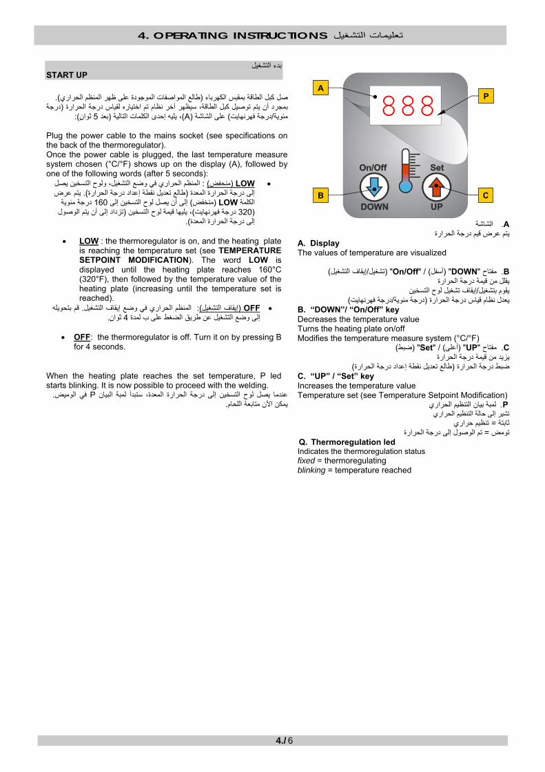
).طالع المواصفات الموجودة على ظهر المنظم الحراري(صل آبل الطاقة بمقبس الكهرباء
درجة (بمجرد أن يتم توصيل آبل الطاقة، سيظهر آخر نظام تم اختياره لقياس درجة الحرارة ): اٍنثو 5بعد (، يليه إحدى الكلمات التالية )A(على الشاشة ) درجة فهرنهايت/مئوية
Plug the power cable to the mains socket (see specifications on the back of the thermoregulator). Once the power cable is plugged, the last temperature measure system chosen (°C/°F) shows up on the display (A), followed by one of the following words (after 5 seconds):
• LOW )المنظم الحراري في وضع التشغيل، ولوح التسخين يصل : )منحفضيتم عرض ). تعديل نقطة إعداد درجة الحرارةطالع (إلى درجة الحرارة المعدة
درجة مئوية 160إلى أن يصل لوح التسخين إلى )منخفض( LOWالكلمة تزداد إلى أن يتم الوصول (ين ، يليها قيمة لوح التسخ)درجة فهرنهايت 320(
). إلى درجة الحرارة المعدة
• LOW : the thermoregulator is on, and the heating plate is reaching the temperature set (see TEMPERATURE SETPOINT MODIFICATION). The word LOW is displayed until the heating plate reaches 160°C (320°F), then followed by the temperature value of the heating plate (increasing until the temperature set is reached).
• OFF )قم بتحويله . المنظم الحراري في وضع إيقاف التشغيل: )إيقاف التشغيل .ثواٍن 4إلى وضع التشغيل عن طريق الضغط على ب لمدة
• OFF: the thermoregulator is off. Turn it on by pressing B
for 4 seconds.
When the heating plate reaches the set temperature, P led starts blinking. It is now possible to proceed with the welding.
. في الوميض Pعندما يصل لوح التسخين إلى درجة الحرارة المعدة، ستبدأ لمبة البيان . يمكن اآلن متابعة اللحام
A. الشاشة
يتم عرض قيم درجة الحرارةA. Display The values of temperature are visualized
B. مفتاح"DOWN) "أسفل" / (On/Off) "إيقاف التشغيل/تشغيل( يقلل من قيمة درجة الحرارة
إيقاف تشغيل لوح التسخين/يقوم بتشغيل )درجة فهرنهايت/درجة مئوية(يعدل نظام قياس درجة الحرارة
B. “DOWN”/ “On/Off” key Decreases the temperature value Turns the heating plate on/off Modifies the temperature measure system (°C/°F)
C. مفتاح"UP) "أعلى" / (Set) "ضبط( يزيد من قيمة درجة الحرارة
)طالع تعديل نقطة إعداد درجة الحرارة(حرارة ضبط درجة الC. “UP” / “Set” key Increases the temperature value Temperature set (see Temperature Setpoint Modification)
P. لمبة بيان التنظيم الحراري تشير إلى حالة التنظيم الحراري
تنظيم حراري= ثابتة ارةتم الوصول إلى درجة الحر= تومض
Q. Thermoregulation led Indicates the thermoregulation status fixed = thermoregulating blinking = temperature reached
888
B C
AP
4. OPERATING INSTRUCTIONS تعليمات التشغيل
4./7
Temperature setpoint modification: :تعديل نقطة إعداد درجة الحرارة
.بدأ القيمة المعروضة في الوميضثواني تقريًبا حتى ت 4 لمدة Cاضغط مع االستمرار على المفتاح •• Keep C pressed for approximately 4 seconds until the value displayed starts blinking.
. إلعداد القيمة المطلوبة Bو Cاضغط على •• Press C and B to set the desired value.
. ميض ويتم حفظها في الذاآرةتتوقف القيمة المعدة عن الو. حرر المفتاحين وانتظر بضع ثواٍن •• Release both keys and wait for a few seconds. The value set halts to blink and is memorized.
How to change the temperature measure system:
:آيفية تغيير نظام قياس درجة الحرارة . اقة، ثم قم بتوصيل مقبس الطBاستمر في الضغط على المفتاح •
• Keep B pressed, and only then connect the power plug. ).ثواني تقريًبا 4سيبدأ نظام القياس المستخدم في الوميض بعد ( Bو Cعن طريق استخدام المفتاح " 002"قم بضبط القيمة •
• Set value “002” by using C and B (the measure system in use will start blinking after approximately 4 seconds). ستتوقف القيمة التي تم إعدادها اآلن عن الوميض وسيتم حفظها في ]). C[ درجة مئوية -] F[ فهرنهايت (لتغيير نظام قياس درجة الحرارة Bو Cاضغط على المفتاح •
.الذاآرة• Press C and B to change the temperature measure system (Fahrenheit [ F ] – Celsius [ °C]). The value now set will halt
to blink and will be memorized.
Error messages: :رسائل الخطأ
. اتصل بمرآز الخدمة المعتمد إذا استمرت المشكلة. إذا ظهرت أي من الرسائل التالية، فحاول إيقاف تشغيل المنظم الحراري ثم إعادة تشغيله If one of the following messages appears, try turning off - turning on the thermoregulator. Contact an authorized service centre if the problem persists.
OP تشير إلى وجود مشكلة في مجس درجة الحرارة؛ قد يكون تالًفا :مجس مفتوح . OP Open Probe: Indicates a problem with the temperature probe; it could be damaged.
OC تشير إلى وجود مشكلة في ضبط درجة الحرارة؛ يتعذر على المنظم الحراري :خارج عن السيطرة .ضبط درجة الحرارة المعدة
OC Out of Control: Indicates a problem with the temperature adjustment; the thermoregulator cannot adjust the temperature set.
Shutdown instructions:
:تعليمات إيقاف التشغيل .)إيقاف التشغيل( OFFإلى أن تظهر آلمة Bإليقاف تشغيل لوح التسخين، اضغط مع االستمرار على المفتاح
To turn off the heating plate, keep B pressed until the word OFF shows up. .إليقاف تشغيل المنظم الحراري، افصل مقبس الطاقة
To turn off the thermoregulator, disconnect the power plug.

4. OPERATING INSTRUCTIONS تعليمات التشغيل
4./8
)3./3 §( قم بضبط الوقت 4.4.1
.t2قم بضبط وقت التسخين : 1المؤقت
).دورة الضغط المزدوج( t6أو ) ة الضغط البسيطدور( t5قم بضبط وقت اللحام : 2المؤقت
4.4.1 Set the time (§ 3./3)
Timer 1: Set the heating time t2.
Timer 2: Set the welding time t5 (Simple Pressure cycle) or t6 (Dual Pressure cycle).
:حضر الشاسيه 4.4.2
.الحد األقصى وافتح الحامالت بالكاملادفع ذراع الموزع إلى
Push the distributor lever to the maximum and open the carriages completely.
:عند الحاجة، أدخل الخافضات. 4.4.3
4.4.3. If needed, insert the reductions:

4. OPERATING INSTRUCTIONS تعليمات التشغيل
4./9
BASIC 200و BASIC 160الموديل
بحيث يتطابق حزها Rأدخل الخافضة . بدون ربطه Vأدخل البرغي .مع جلبة الفك
.لتثبيت الخافضة بالفك Vاربط البرغي
. آرر العملية مع الفك اآلخر
BASIC 355و BASIC 315و BASIC 250 الموديالت
داخل حز الفك، بحيث تثبت الخافضة على) انظر السهم(أدخل طرف الخافضة . Sالمسمار
Pتحقق من أن . للسماح باإلدخال بالكامل وربط الخافضة Pاضغط على المفتاح
. يعود إلى وضعه األولي، بعد ذلك
. آرر العملية مع الفك اآلخر
160 BASIC and 200 BASIC models Insert the V screw without fastening it. Insert the R reduction so that its groove coincides with the jaw’s bushing. Fasten the V screw to lock the reduction to the jaw. Repeat the operation with the other jaw.
250 BASIC, 315 BASIC and 355 BASIC models
Insert the reduction end (see arrow) inside the jaw’s groove, so that the reduction lays on the S pin. Press P key to allow complete insertion and fastening of the reduction. Make sure that P returns to its initial position, afterwards. Repeat the operation with the other jaw.
P
S
R
V
V
P
S
R
V
V

4. OPERATING INSTRUCTIONS تعليمات التشغيل
4./10
3aو 2aآيفية اللحام بين القامطة رقم
.آما هو موضح أدناه Bلوح التسخين مع اللوحات المعدنية لتحرير Aقم بتجميع قضبان السحب
HOW TO WELD BETWEEN CLAMPS NUMBER 2a AND 3a
Assembly the dragging bars A and the heating plate release plaques B as shown in the image below.
.أدخل العناصر التي سيتم لحامها داخل القامطات وقم بربطها
Insert the elements to be welded inside the clamps and fasten them.
!هام
غير موجودة Bاللوحات المعدنية لتحرير لوح التسخين . BASIC 200و BASIC 160في الموديل
1a
2a
3a
4a
B A
B
A
AB
Important! The heating plate release plaques B are not featured in the BASIC 160 and BASIC 200 models.
1a
2a
3a
4a
B A
B
A
A B

4. OPERATING INSTRUCTIONS تعليمات التشغيل
4./11
4aو 3aآيفية اللحام بين القامطات رقم
.آما هو موضح أدناه Bحات المعدنية لتحرير لوح التسخين مع اللو Aقم بتجميع قضبان السحب
HOW TO WELD BETWEEN CLAMPS NUMBER 3a AND 4a
Assembly the dragging bars A and the heating plate release plaques B as shown in the image below.
.أدخل العناصر التي سيتم لحامها داخل القامطات وقم بربطها
1a
2a
3a
4a
A B
!هام
غير موجودة Bاللوحات المعدنية لتحرير لوح التسخين .BASIC 200و BASIC 160في الموديل
BA
BA
1a
2a
3a
4a
A B
Important! The heating plate release plaques B are not featured in the BASIC 160 and BASIC 200 models.
B A
B A

4. OPERATING INSTRUCTIONS تعليمات التشغيل
4./12
Insert the elements to be welded inside the clamps and fasten them.

4. OPERATING INSTRUCTIONS تعليمات التشغيل
4./13
التسوية
ضع المسواة بين الطرفين اللذين سيتم لحامها. 4.6.1
.يب الكباس السفليضع المسواة على قض
.Mثبت المسواة عند قضيب الكباس العلوي بمساعدة الذراع المانع
).أخضر(قم بتشغيل المسواة عن طريق الضغط على زر البدء االنضغاطي . 4.6.2
.يواجهان بعضهما البعض بدون الضغط بإفراط على المحرك قارب الطرفين اللذين سيتم لحامهما واجعلهما
.من الطرفين، توقف عن التسوية وافتح الحامالت) متساوية(بمجرد أن تحصل على رقاقة متصلة ومتجانسة . 4.6.3
).رأحم(أغلق المحرك عن طريق الضغط على زر اإليقاف االنضغاطي
.قم بإزالة الرقائق بدون لمس أو تلويث األطراف التي تمت تسويتها. قم بإزالة المسواة وضعها في المبيت الخاص بها
FACING
M

4. OPERATING INSTRUCTIONS تعليمات التشغيل
4./14
4.6.1. Position the facer in between the ends to be welded
Rest the facer on the lower piston rod.
Anchor the facer at the upper piston rod with the help of the blocking lever M.
4.6.2. Turn on the facer by pressing the start push button (green). Approach and face both ends to be welded without overstressing the motor.
4.6.3. As soon as you get a continuous and uniformed (even) chip on both ends, stop the facing and open the carriages. Shut down the motor by pressing the stop push button (red). Remove the facer and place it in its housing. Remove the chips without touching or fouling the faced ends.
M

4. OPERATING INSTRUCTIONS تعليمات التشغيل
4./15
.Ptقراءة ضغط السحب
ادفع ذراع الموزع إلى الحد األقصى . 4.7.1 .وافتح الحامالت بالكامل
قم بتصفير الضغط داخل الدائرة .4.7.2الهيدروليكية عن طريق تدوير صمام الحد
.األقصى للضغط عكس اتجاه عقارب الساعة
هو الحد األدنى Ptضغط السحب . 4.7.3 .المطلوب من الضغط لتحريك الحاملة المتحرآة
صمام الحد األقصى للضغط في اتجاه عقارب الساعة وبصورة تدريجية، إلى أن تتحرك اسحب ذراع الموزع إلى الحد األقصى مع زيادة القوة بصورة تدريجية، ولف . الموجود على المانومتر وقم بتسجيله) Pt(اقرأ الضغط . الحاملة المتحرآة
. قبل آل عملية لحام Ptيجب أن يتم قياس قيمة :يرجى االنتباه
READING THE DRAGGING PRESSURE Pt.
4.7.1. Push the distributor lever to the maximum and open the carriages completely.

4. OPERATING INSTRUCTIONS تعليمات التشغيل
4./16
4.7.2. Zeroize the pressure inside the hydraulic circuit by rotating the maximum pressure valve in a counterclockwise manner.
4.7.3. L he dragging pressure Pt is the minimum pressure required to get the movable carriage in motion.
Pull the distributor lever to the maximum with gradual increasing force, and rotate the maximum pressure valve in a clockwise and gradual manner, until the movable carriage gets in motion. Read the pressure (Pt) on the manometer and write it down.
Attention please: The Pt value must be measured prior to each and every welding.
دورة اللحام بالضغط البسيط .تذآر ملء تقرير اللحام عند آل مرحلة
.وس الهيدروليكيةفي علبة التر) P1+Pt( المرحلة األولىآيفية ضبط ضغط
قارب الحامالت واجعل ذراع الموزع مسحوًبا إلى أقصى
.درجة ممكنة
لف صمام الحد األقصى للضغط في اتجاه عقارب الساعة حتى يظهر على المانومتر أنه تم الوصول إلى مستوى الضغط
)P1+Pt(.
.ادفع ذراع الموزع وافتح الحامالت
SIMPLE PRESSURE WELDING CYCLE Remember to fill out the welding report at each phase. How to set the PHASE 1 pressure (P1+Pt) on the hydraulic gearcase.

4. OPERATING INSTRUCTIONS تعليمات التشغيل
4./17
Approach the carriages and keep the distributor level pulled to the maximum.
Rotate the maximum pressure valve in a clockwise manner until the manometer shows that the pressure (P1+Pt) has been reached.
Push the distributor lever and open the carriages.

4. OPERATING INSTRUCTIONS تعليمات التشغيل
4./18
االقتراب والتسخين المسبق: المرحلة األولى
بمجرد أن تتأآد من أن درجة حرارة لوح المطلوبة، التسخين هي درجة الحرارة .أدخل الطرفين اللذين سيتم لحامهما
). وفًقا للمعيار المستخدم(المطلوبين ) DVS 2207(أو االرتفاع ) UNI 10520(انتظر حتى الخرزة إلى العرض . )P1+Pt(أغلق الحامالت وحافظ على الضغط
.حرر ذراع الموزع
التسخين: لثانيةالمرحلة ا
فك صمام تصريف الضغط لولبًيا بطريقة تدريجية حتى يتم الوصول إلى الحد األقصى
. P2للضغط
للحفاظ على الطرفين P2يكفي مستوى الضغط .متالمسين مع لوح التسخين
أغلق صمام تصريف الضغط عن طريق
. تدويره في اتجاه عقارب الساعة
. t2الوقت انتظر حتى ينتهي
، تأآد من أن الطرفين ال t2أثناء الوقت إذا حدث ذلك، . ينفصالن أبًدا من لوح التسخين
.فإنه يجب تكرار عملية اللحام من البداية
1المؤقت
=t2

4. OPERATING INSTRUCTIONS تعليمات التشغيل
4./19
PHASE 1: Approach and Pre-heating
Once you are sure that the temperature of the heating plate is the one required, insert it in between the ends to be welded.
Close the carriages and keep the pressure (P1+Pt). Wait until the bead reaches the width (UNI 10520) or height (DVS 2207) required (depends on the standard being used).
Slowly release the distributor lever.
PHASE 2: Heating
Unscrew the pressure discharge valve in a gradual manner until the maximum pressure P2 is reached. P2 is sufficient to keep the ends in touch with the heating plate. Close the pressure discharge valve by rotating it in a clockwise manner.
Wait for the t2 time to end. During the t2 time, be sure that the ends NEVER detach from the heating plate. Should this happen, the welding MUST be repeated from the beginning.
Timer 1
= t2
4. OPERATING INSTRUCTIONS تعليمات التشغيل
4./20
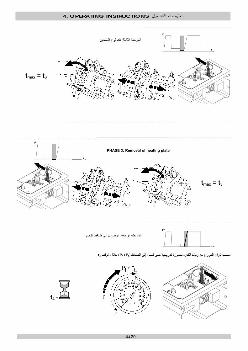
فك لوح التسخين: المرحلة الثالثة
tmax = t3
PHASE 3: Removal of heating plate
tmax = t3
اللحامالوصول إلى ضغط : المرحلة الرابعة
. t4خالل الوقت )P1+Pt(اسحب ذراع الموزع مع زيادة القدرة بصورة تدريجية حتى تصل إلى الضغط
=t4
4. OPERATING INSTRUCTIONS تعليمات التشغيل
4./21
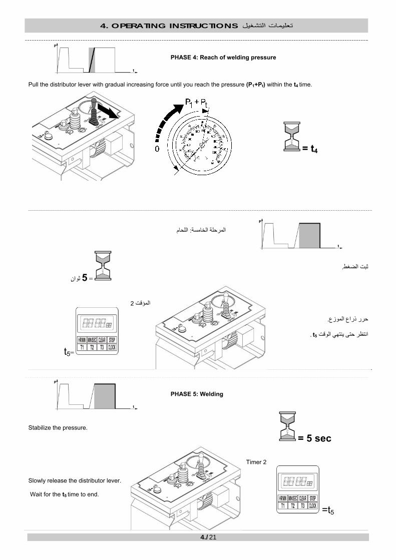
PHASE 4: Reach of welding pressure
Pull the distributor lever with gradual increasing force until you reach the pressure (P1+Pt) within the t4 time.
= t4
اللحام: المرحلة الخامسة
.ثبت الضغط ثواٍن 5=
.حرر ذراع الموزع
. t5انتظر حتى ينتهي الوقت
2المؤقت
=t5
PHASE 5: Welding
Stabilize the pressure.
= 5 sec
Slowly release the distributor lever. Wait for the t5 time to end.
Timer 2
=t5

4. OPERATING INSTRUCTIONS تعليمات التشغيل
4./22
التبريد: المرحلة السادسة
قم بتصفير الضغط عن طريق لف صمام تصريف .الضغط لولبًيا بالكامل
.انتظر حتى يبرد المفصل بالكامل قبل إزالته من الماآينة
=t6
PHASE 6: Cooling
Zeroize the pressure by unscrewing the pressure discharge valve completely.
Wait until the joint has cooled down before removing it from the machine.
= t6
:عند اآتمال اللحام
. افتح القامطات وفك الماسورة الملحومة
. مقبس الماآينة من مصدر إمداد الطاقة عند انتهاء العملياتفك
.افصل المكونات
. نظفها بطريقة صحيحة
.ضعها في الدعامات الخاصة بها

4. OPERATING INSTRUCTIONS تعليمات التشغيل
4./23
WHEN WELDING COMPLETED: Open the clamps and remove the welded pipe. Unplug the machine from the power supply at the end of operations. Disconnect the components. Clean them accurately. Put them in their supports.
دورة اللحام بالضغط المزدوج
.ملم أو يفوق ذلك 20بسمك يعادل PE 100تستخدم دورة الضغط المزدوج عند لحام
. طملم، استخدم دورة الضغط البسي 20بسمك يقل عن PE 100عند لحام
. لما يتعلق بدورة الضغط البسيط، ثم تابع آما هو موضح أدناه(المراحل األربع األولى متماثلة
.تذآر ملء تقرير اللحام عند آل مرحلة
DUAL PRESSURE WELDING CYCLE The Dual Pressure cycle is used when welding PE 100 with thickness equal or superior to 20 mm. When welding PE 100 with thickness inferior to 20 mm, use the Simple Pressure cycle. The first four phases are identical (with respect to the Simple Pressure cycle, then proceed as indicated below. Remember to fill out the welding report at each phase.
الجزء األول -اللحام : المرحلة الخامسة
حافظ على ذراع الموزع مسحوًبا إلى الحد .األقصى
ثواٍن 10=
.حرر ذراع الموزع
PHASE 5: Welding – FIRST PART
Keep the distributor lever pulled to the maximum..
= 10 sec
Slowly release the distributor lever.

4. OPERATING INSTRUCTIONS تعليمات التشغيل
4./24
الجزء الثاني -اللحام : المرحلة السادسة
عن P6قم بتصريف الضغط إلى طريق لف صمام تصريف الضغط
.لولبًيا
. t6انتظر حتى ينتهي الوقت
2المؤقت
=t6
PHASE 6: Welding – SECOND PART
Discharge pressure down to P6 by unscrewing the pressure discharge valve. Wait for the t6 time to end.
Timer 2
= t6
التبريد: المرحلة السابعة
قم بتصفير الضغط عن طريق لف صمام تصريف .الضغط لولبًيا بالكامل
.امل قبل إزالته من الماآينةانتظر حتى يبرد المفصل بالك
=t7

4. OPERATING INSTRUCTIONS تعليمات التشغيل
4./25
PHASE 7: Cooling
Zeroize the pressure by unscrewing the pressure discharge valve completely.
Wait until the joint has cooled down before removing it from the machine.
= t7
. الماسورة الملحومة افتح القامطات وفك
. فك مقبس الماآينة من مصدر إمداد الطاقة عند انتهاء العمليات
.افصل المكونات
. نظفها بطريقة صحيحة
.ضعها في الدعامات الخاصة بها
.املء تقرير اللحام عند اآتمال آل مرحلة من مراحل اللحام
Open the clamps and remove the welded pipe. Unplug the machine from the power supply at the end of operations. Disconnect the components. Clean them accurately. Put them in their supports.
Fill in the welding report as each welding phase is completed.
5. MAINTENANCE الصيانة
5./1
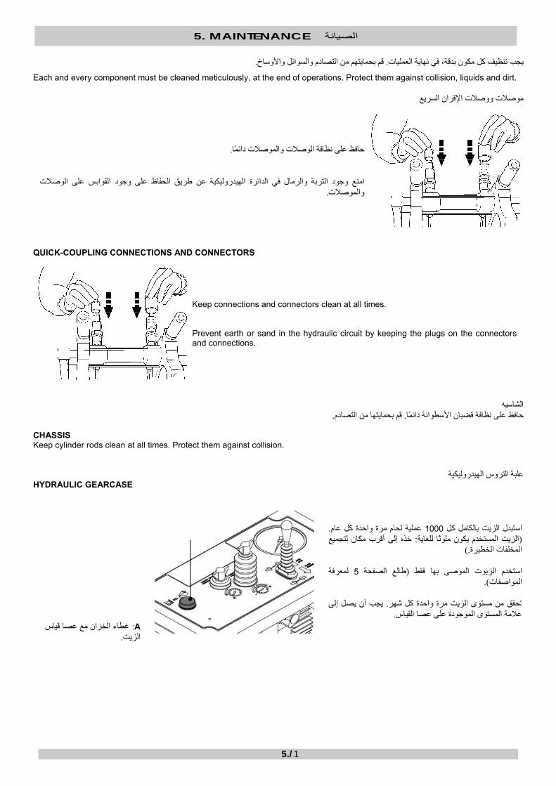
.قم بحمايتهم من التصادم والسوائل واألوساخ. يجب تنظيف آل مكون بدقة، في نهاية العمليات
Each and every component must be cleaned meticulously, at the end of operations. Protect them against collision, liquids and dirt.
موصالت ووصالت اإلقران السريع
.على نظافة الوصالت والموصالت دائًماحافظ
امنع وجود التربة والرمال في الدائرة الهيدروليكية عن طريق الحفاظ على وجود القوابس على الوصالت .والموصالت
QUICK-COUPLING CONNECTIONS AND CONNECTORS
Keep connections and connectors clean at all times. Prevent earth or sand in the hydraulic circuit by keeping the plugs on the connectorsand connections.
الشاسيه
. قم بحمايتها من التصادم. حافظ على نظافة قضبان األسطوانة دائًما
CHASSIS
Keep cylinder rods clean at all times. Protect them against collision.
روس الهيدروليكيةعلبة الت
HYDRAULIC GEARCASE
. عملية لحام مرة واحدة آل عام 1000استبدل الزيت بالكامل آل خذه إلى أقرب مكان لتجميع : الزيت المستخدم يكون ملوًثا للغاية(
.)المخلفات الخطيرة
لمعرفة 5طالع الصفحة (استخدم الزيوت الموصى بها فقط ). المواصفات
يجب أن يصل إلى . تحقق من مستوى الزيت مرة واحدة آل شهر .عالمة المستوى الموجودة على عصا القياس
A : غطاء الخزان مع عصا قياس .الزيت

5. MAINTENANCE الصيانة
5./2
Completely replace oil each 1000 weldings and at least once a year. (Used oil is very pollutant: take it to the nearest hazardous waste collection site.) Use recommended oils only (see page 5 for specifications). Check the oil level once a month. It must reach the level mark at the dipstick.
A: Tank cap with oil dipstick.
لوح التسخين
. بعد العمليات) لحماية الطالء(نظف لوح التسخين وضعه في المبيت الخاص ب
HEATING PLATE
Clean and place the heating plate in its housing (for coating protection) after operations.
FACER المسواة
. استبدل الشفرتين بصورة دورية .ف المسواة وضعها في المبيت الخاص بها بعد إجراء العملياتنظ
Replace both blades periodically. Clean and place the facer in its housing after operations.
A
6. TROUBLE SHOOTING تحري األعطال وإصالحها
6./1
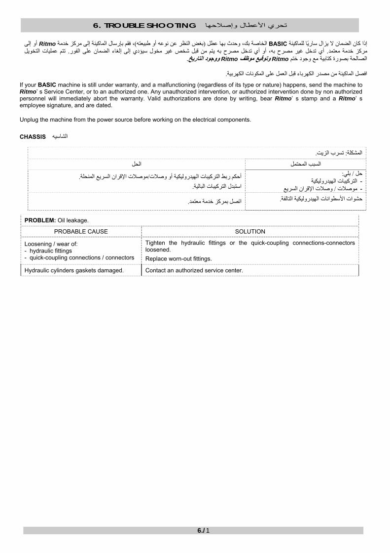
أو إلى Ritmo، فقم بإرسال الماآينة إلى مرآز خدمة )بغض النظر عن نوعه أو طبيعته(الخاصة بك، وحدث بها عطل BASICإذا آان الضمان ال يزال سارًيا للماآينة تتم عمليات التخويل . لفورأي تدخل غير مصرح به، أو أي تدخل مصرح به يتم من قبل شخص غير مخول سيؤدي إلى إلغاء الضمان على ا. مرآز خدمة معتمد
. ووجود التاريخ Ritmoوتوقيع موظف Ritmoالصالحة بصورة آتابية مع وجود ختم
. افصل الماآينة من مصدر الكهرباء قبل العمل على المكونات الكهربية
If your BASIC machine is still under warranty, and a malfunctioning (regardless of its type or nature) happens, send the machine to Ritmo’ s Service Center, or to an authorized one. Any unauthorized intervention, or authorized intervention done by non authorized personnel will immediately abort the warranty. Valid authorizations are done by writing, bear Ritmo’ s stamp and a Ritmo’ s employee signature, and are dated.
Unplug the machine from the power source before working on the electrical components.
CHASSIS الشاسيه
.تسرب الزيت :المشكلة الحل السبب المحتمل
:بلي/ حل الترآيبات الهيدروليكية - وصالت اإلقران السريع/ موصالت -
. موصالت اإلقران السريع المنحلة/أحكم ربط الترآيبات الهيدروليكية أو وصالت
.استبدل الترآيبات البالية
.حشوات األسطوانات الهيدروليكية التالفة
.اتصل بمرآز خدمة معتمد
PROBLEM: Oil leakage.
PROBABLE CAUSE SOLUTION
Loosening / wear of: - hydraulic fittings - quick-coupling connections / connectors
Tighten the hydraulic fittings or the quick-coupling connections-connectors loosened.
Replace worn-out fittings.
Hydraulic cylinders gaskets damaged.
Contact an authorized service center.
6. TROUBLE SHOOTING تحري األعطال وإصالحها
6./2
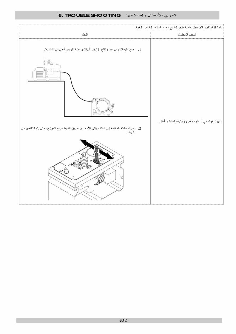
.حاملة متحرآة مع وجود قوة حرآة غير آافية. نقص الضغط :المشكلة
الحل السبب المحتمل
.وجود هواء في أسطوانة هيدروليكية واحدة أو أآثر
).يجب أن تكون علبة التروس أعلى من الشاسيه( hضع علبة التروس عند ارتفاع .1
حرك حاملة الماآينة إلى الخلف وإلى األمام عن طريق تنشيط ذراع الموزع، حتى يتم التخلص من .2 .الهواء

6. TROUBLE SHOOTING تحري األعطال وإصالحها
6./3
PROBLEM: Lack of pressure. Movable carriage with insufficient movement force.
PROBABLE CAUSE SOLUTION
Air in one or both hydraulic cylinders.
3. Position the gearcase at a h height (gearcase ought to be higher than the chassis).
4. Move the machine carriage back and forward by activating the distributor lever, until air is eliminated.
h
6. TROUBLE SHOOTING تحري األعطال وإصالحها
6./4
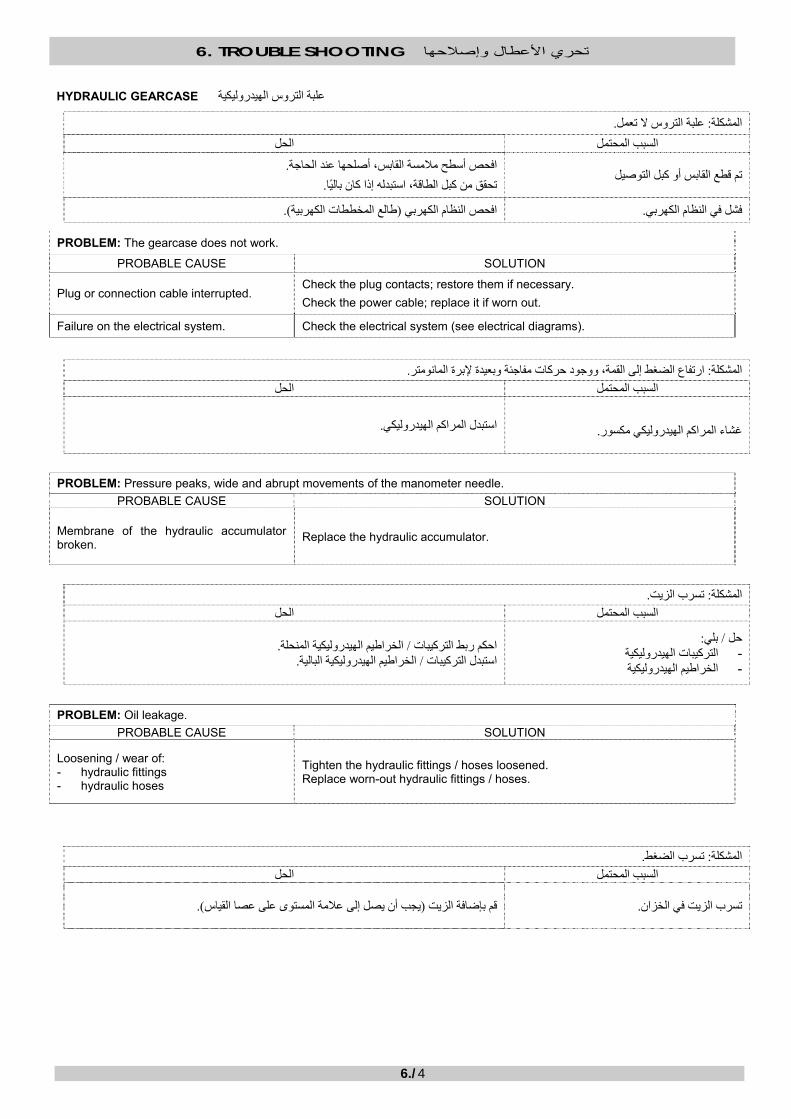
HYDRAULIC GEARCASE علبة التروس الهيدروليكية
.علبة التروس ال تعمل: المشكلة الحل السبب المحتمل
تم قطع القابس أو آبل التوصيل
. افحص أسطح مالمسة القابس، أصلحها عند الحاجة
. تحقق من آبل الطاقة، استبدله إذا آان بالًيا
.فشل في النظام الكهربي
).طات الكهربيةطالع المخط(افحص النظام الكهربي
PROBLEM: The gearcase does not work. PROBABLE CAUSE SOLUTION
Plug or connection cable interrupted.
Check the plug contacts; restore them if necessary.
Check the power cable; replace it if worn out.
Failure on the electrical system.
Check the electrical system (see electrical diagrams).
.ارتفاع الضغط إلى القمة، ووجود حرآات مفاجئة وبعيدة إلبرة المانومتر :المشكلة
الحل السبب المحتمل
.غشاء المراآم الهيدروليكي مكسور
.استبدل المراآم الهيدروليكي
PROBLEM: Pressure peaks, wide and abrupt movements of the manometer needle.
PROBABLE CAUSE SOLUTION Membrane of the hydraulic accumulator broken.
Replace the hydraulic accumulator.
.تسرب الزيت: المشكلة
الحل السبب المحتمل
:بلي/ حل الترآيبات الهيدروليكية - الخراطيم الهيدروليكية -
.الخراطيم الهيدروليكية المنحلة/ ربط الترآيبات احكم .الخراطيم الهيدروليكية البالية/ استبدل الترآيبات
PROBLEM: Oil leakage.
PROBABLE CAUSE SOLUTION
Loosening / wear of: - hydraulic fittings - hydraulic hoses
Tighten the hydraulic fittings / hoses loosened. Replace worn-out hydraulic fittings / hoses.
.تسرب الضغط :المشكلة الحل السبب المحتمل
. تسرب الزيت في الخزان
).يجب أن يصل إلى عالمة المستوى على عصا القياس(قم بإضافة الزيت

6. TROUBLE SHOOTING تحري األعطال وإصالحها
6./5
.وجود هواء في الدائرة الهيدروليكية
.موصالت اإلقران السريع -جّمع وصالت
ثانية عن 30قم بتشغيل محرك علبة التروس لمدة
. طريق سحب ذراع الموزع
.وجود تلوث في الدائرة الهيدروليكية
.اتصل بمرآز خدمة معتمد
PROBLEM: Lack of pressure.
PROBABLE CAUSE SOLUTION
Lack of oil in the tank. Add oil (it must reach the level mark at the dipstick).
Air in the hydraulic circuit.
Unite the quick-coupling connectors - connections.
Activate the gearcase motor for 30 seconds by pulling the distributor lever.
Impurity in the hydraulic circuit.
Contact an authorized service center.
6. TROUBLE SHOOTING تحري األعطال وإصالحها
6./6
HEATING PLATE لوح التسخين
. افصل الماآينة من مصدر الكهرباء قبل العمل على المكونات الكهربية
Unplug the machine from the power source before working on the electrical components.
.بط درجة الحرارة، ولكن لمبات البيان تعمللوح التسخين ال يقوم بالتسخين أو يستحيل ض :المشكلة
الحل السبب المحتمل
.استبدل المنظم الحراري فشل المنظم الحراري
.استبدل المنظم الحراري فشل المنظم الحراري
PROBLEM: The heating plate does not heat or it is impossible to adjust the temperature, but LEDS work.
PROBABLE CAUSE SOLUTION
Thermoregulator failure Replace the thermoregulator.
Thermoregulator failure Replace the thermoregulator.
.لوح التسخين ال يقوم بالتسخين أو يستحيل ضبط درجة الحرارة، ولمبة البيان الخضراء مطفأة :المشكلة
الحل السبب المحتمل .استبدل المنظم الحراري نظم الحراريفشل الم
.استبدل المنظم الحراري فشل المنظم الحراري
PROBLEM: The heating plate does not heat or it is impossible to adjust the temperature, and green LED is off.
PROBABLE CAUSE SOLUTION
Thermoregulator failure Replace the thermoregulator.
Thermoregulator failure Replace the thermoregulator.
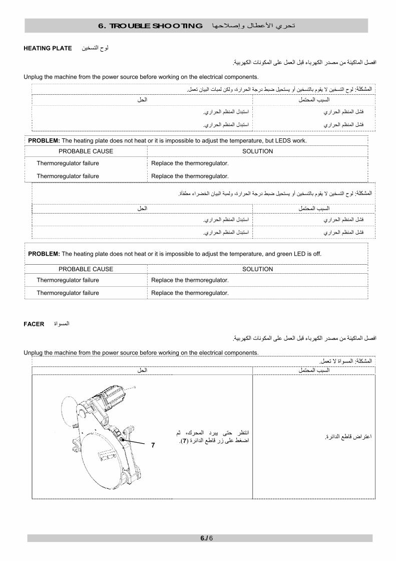
FACER المسواة
. افصل الماآينة من مصدر الكهرباء قبل العمل على المكونات الكهربية
Unplug the machine from the power source before working on the electrical components.
.المسواة ال تعمل :المشكلة الحل السبب المحتمل
انتظر حتى يبرد المحرك، ثم .اعتراض قاطع الدائرة ).7(اضغط على زر قاطع الدائرة
7
6. TROUBLE SHOOTING تحري األعطال وإصالحها
6./7
.وصلة منقطعة
.آبل الطاقة منقطع
افحص النظام . اجة، وأعد توصيلها عند الح)الدائرة الكهربية والمقبس(تحقق من أسطح مالمسة اللوحة
. الكهربي
. تحقق من آبل الطاقة، واستبدله إذا آان بالًيا
.المفتاح الدقيق غير فعال أو غير موجود في مكانه
فك لوحة الحماية واستبدل المفتاح الدقيق، أو اضبط موضعه باستخدام
حتى يتم قفل سطح Bو Aالبرغي المالمسة فقط عن طريق وضع
الكباس المسواة على قضيب .العلوي
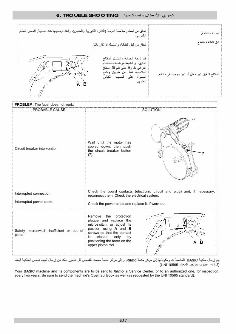
PROBLEM: The facer does not work.
PROBABLE CAUSE SOLUTION
Circuit breaker intervention.
Wait until the motor has cooled down, then push the circuit breaker button (7).
Interrupted connection. Interrupted power cable.
Check the board contacts (electronic circuit and plug) and, if necessary, reconnect them. Check the electrical system. Check the power cable and replace it, if worn-out.
Safety microswitch inefficient or out of place.
Remove the protection plaque and replace the microswitch, or adjust its position using A and B screws so that the contact is closed only by positioning the facer on the upper piston rod.
تأآد من إرسال آتيب فحص الماآينة أيًضا . آل عامينخدمة معتمد، للفحص أو إلى مرآز Ritmoالخاصة بك ومكوناتها إلى مرآز خدمة BASICيتم إرسال ماآينة ). UNI 10565آما هو مطلوب بموجب المعيار (
Your BASIC machine and its components are to be sent to Ritmo’ s Service Center, or to an authorized one, for inspection, every two years. Be sure to send the machine’s Overhaul Book as well (as requested by the UNI 10565 standard).
7

7. SAFETY PRECAUTION احتياطات السالمة
7./1
INTRODUCTION مقدمة
.فقط(*) من قبل األفراد المهرة والمعتمدين BASICتستخدم ماآينات اللحام
). UNI 9737مثل، (معتمدون وفًقا للقانون واللوائح السارية (*)
يجب اعتبار أي استخدام . دائًماتخدام والصيانة الواردة هنا ووفًقا لتعليمات االس" مقدمة للمنتج والمواصفات" 1للوظائف الوارد وصفها في الفصل فقطتستخدم الماآينة .أو بالماآينة نفسها/األجسام األخرى، و/األطراف الثالثة/آخر غير مالئم وبالتالي يكون ممنوًعا، حيث إنه قد يتسبب في حدوث ضرر في التشغيل
.دائًمايجب أخذ احتياطات السالمة الواردة هنا في عين االعتبار
).مثل المفاتيح والمفاتيح الدقيقة وموانع التسرب، إلخ(الي من الممنوع منًعا بًتا إزالة أي جهاز للسالمة وبالت
. األصلية فقط Ritmoاستبدل على الفور أي مكون باٍل أو تالف بقطع غيار
. يجب أن يتم أي شكل من أشكال التدخل على الماآينة من قبل أفراد مهرة ومؤهلين
The use of the welding machines BASIC is intended for skilled and certified (*) personnel only. (*) Certified according to the Legislation and regulations in force (e.g., UNI 9737). The machine is to be used only for the functions described in Chapter 1 “Product Introduction and Specifications” and always according to the instructions for use and maintenance herein. Any other use shall be considered improper and is therefore forbidden, as it may cause damage to the operator/third parties/other objects, and/or to the machine itself. The Safety Precautions herein indicated must be taken into consideration at all times. It is strictly forbidden to remove each and every safety device (e.g., switches, microswitches, seals, etc.). Promptly replace any worn-out or damaged component with original Ritmo spare parts, only. Any sort of intervention on the machine must be done by authorized skilled and qualified personnel only.
ELECTRICAL HAZARDS المخاطر الكهربية
خطر اإلعدام بالكهرباء
علبة التروس الهيدروليكية :القطع المتضمنة المسواة لوح التسخين
.تأآد دائًما من أن المواصفات الكهربية إلمداد الطاقة تتوافق مع المواصفات الخاصة بالماآينة
.قم بتأريض الماآينة
.ل بطريقة صحيحة أم الراقب ما إذا آان النظام المؤرض يعم

7. SAFETY PRECAUTION احتياطات السالمة
7./2
).مللي أمبير IΔ=30(تأآد من أن لوحة المفاتيح الكهربية أو من أن المولد الذي تتصل به الماآينة أثناء التشغيل يشتمل على مفتاح تفاضلي حساس
. IP44مع أدنى درجة من الحماية IEC 309يجب أن تنتمي مقابس لوحة المفاتيح الكهربية إلى النوع
. ع الماآينة تتعرض إلى األمطار أو إلى أي سوائل أخرىال تد
.جافة تماًما عند استخدام الماآينة) مثل قفازات السالمة(تأآد من أن أجهزة حماية العزل
المرآبات أو للمارة، إلخأو للمخاطر العامة مثل حبال الشد أو األجسام الحادة أو لممر ال تدع الكبالت مكشوفة للمواد الكيميائية أو للجهد الميكانيكي
. افصل الماآينة من مصدر الطاقة بمجرد انتهاء العمليات، أو حتى عند تعليق العمليات لفترة قصيرة
.انتبه بصورة خاصة للقطع العازلة وأدلة تمرير الكبالت وجلب الكبالت. تحقق من سالمة جميع المكونات قبل استخدام الماآينة
. مفتاح التفاضلي مرة واحدة آل شهراختبر التدخل الصحيح لل
المواد القابلة لالشتعال (ال تستخدم مواد قد تؤدي إلى تلف قطع العزل، مثل مذيبات التنظيف الجاف أو البنزين . نظف الماآينة ومكوناتها بالكامل بعد االستخدام
. أو السوائل الكاشطة) بصورة عامة
IECاستخدم النوع . السارية وأن تكون مناسبة للطاقة المطلوبةيجب أن تتوافق التمديدات مع اللوائح . فقط IP67، المقابس 309
: تكون مطلوبة عند العمل في) SELV(معدة فولطية األمان المنخفضة للغاية
األماآن الضيقة - األماآن شديدة الرطوبة - )ناء السفنمثل مواضع ب(األماآن المحاطة بالهياآل المعدنية أو بالمياه -
ELECTROCUTION HAZARD Parts involved: HYDRAULIC GEARCASE FACER HEATING PLATE
Be sure that the electrical specifications of the power supply correspond to the ones of the machine.
Earth the machine. Control if the earthed system is working properly.
7. SAFETY PRECAUTION احتياطات السالمة
7./3
Be sure that the panel board or the generator to which the machine is connected during operations has a highly sensitive differential switch (IΔ=30mA). The panel board plugs must belong to the IEC 309 type with IP44 minimum protection degree. Do not let the machine be exposed to rain or any other liquids. Be sure that the isolating protection devices (such as the safety gloves) are perfectly dry when you use the machine. Dot not let the cables be exposed to chemical substances, mechanical strain, or general hazards such as tugs, sharp objects, or the passage of vehicles or passers-by, etc. Unplug the machine from the power source as soon as operations are over, or even momentarily suspended. Check the integrity of all components before using the machine. Pay particular attention to the isolating parts, cables, cable fairleads and cable glands. Test the proper intervention of the differential switch once a month. Thoroughly clean the machine and its components after use. Do not use substances that could damage the isolating parts, such as solvents, gasoline (combustibles in general), or abrasive liquids.
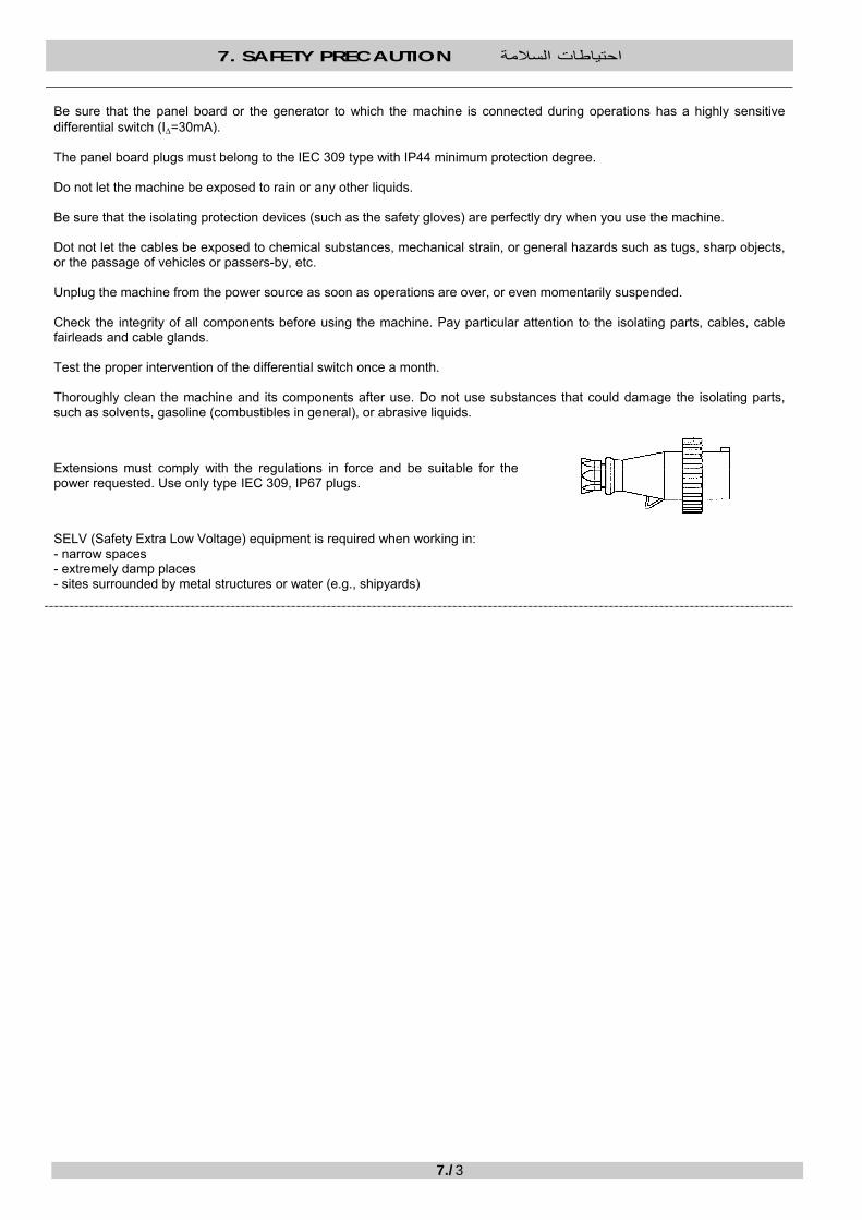
Extensions must comply with the regulations in force and be suitable for thepower requested. Use only type IEC 309, IP67 plugs.
SELV (Safety Extra Low Voltage) equipment is required when working in: - narrow spaces - extremely damp places - sites surrounded by metal structures or water (e.g., shipyards)
7. SAFETY PRECAUTION احتياطات السالمة
7./4
MECHANICAL HAZARDS المخاطر الميكانيكية
خطر السحق
الشاسيه :القطع المتضمنة
Tenersi a distanza di sicurezza durante il movimento del carrello.
). يجب أن يكون الذراع متجًها نحو المانومتر(عند حدوث سحق، قم على الفور بتشغيل ذراع الموزع لفتح الحامالت !!! : انتبه
.ثبات الماآينة دائًماتأآد من
. تأآد من أن العناصر التي سيتم لحامها، والقامطات، مثبتة بطريقة صحيحة وبإحكام
. مارس سالمة العمل دائًما
.ارتِد أحذية السالمة دائًما
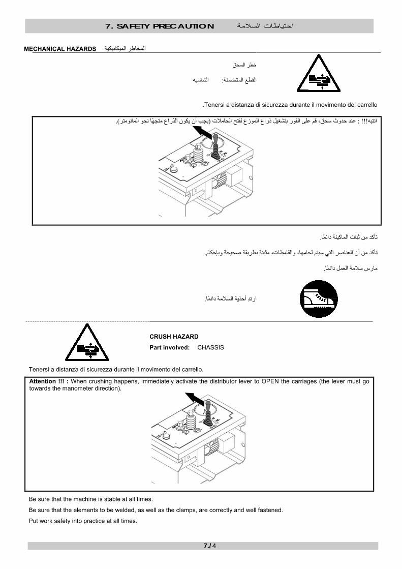
CRUSH HAZARD
Part involved: CHASSIS
Tenersi a distanza di sicurezza durante il movimento del carrello.
Attention !!! : When crushing happens, immediately activate the distributor lever to OPEN the carriages (the lever must go towards the manometer direction).
Be sure that the machine is stable at all times.
Be sure that the elements to be welded, as well as the clamps, are correctly and well fastened.
Put work safety into practice at all times.
7. SAFETY PRECAUTION احتياطات السالمة
7./5
Always wear your safety shoes.
خطر القطع
المسواة :القطع المتضمنة
.حافظ على وجود مسافة آمنة من الماآينة أثناء عمل المسواة
.تعامل مع المسواة بحذر
.ارتِد قفازات السالمة دائًما
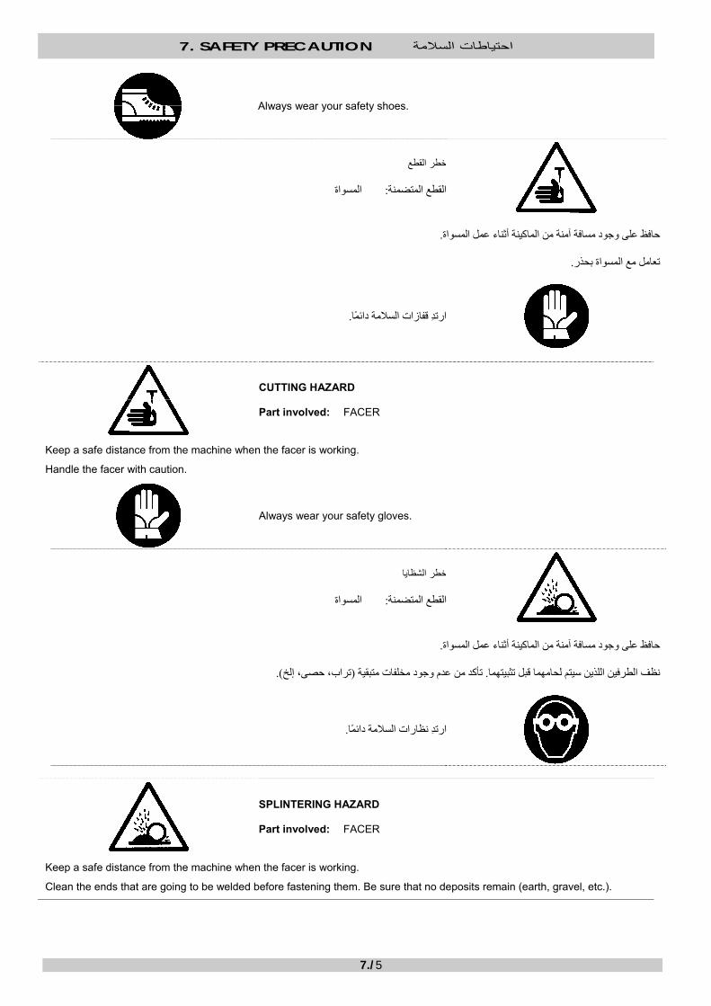
CUTTING HAZARD Part involved: FACER
Keep a safe distance from the machine when the facer is working.
Handle the facer with caution.
Always wear your safety gloves.
خطر الشظايا
المسواة :القطع المتضمنة
.حافظ على وجود مسافة آمنة من الماآينة أثناء عمل المسواة
).، إلختراب، حصى(تأآد من عدم وجود مخلفات متبقية . نظف الطرفين اللذين سيتم لحامهما قبل تثبيتهما
.ارتِد نظارات السالمة دائًما
SPLINTERING HAZARD Part involved: FACER
Keep a safe distance from the machine when the facer is working.
Clean the ends that are going to be welded before fastening them. Be sure that no deposits remain (earth, gravel, etc.).

7. SAFETY PRECAUTION احتياطات السالمة
7./6
Always wear your safety glasses/goggles.

7. SAFETY PRECAUTION احتياطات السالمة
7./7
اآللية المتحرآة
الوقوع في شرك/ خطر التشابك
الشاسيه :القطع المتضمنة المسواة
. حافظ على وجود مسافة آمنة من الماآينة عند تحرك الحمولة المتحرآة أو عند عمل المسواة
. ال تستخدم المالبس الفضفاضة. قم بلم الشعر الطويل. م بإزالة جميع األساور والقالداتق
.ارتِد ثياب السالمة دائًما
Moving Machinery
ENTANGLEMENT / ENTRAPMENT HAZARD Parts involved: CHASSIS FACER
Keep a safe distance from the machine when the movable carriage is in motion or when the facer is working. Remove all your bracelets and necklaces. Gather up long hair. Do not use loose clothing.
Always wear your safety coverall.
THERMAL HAZARDS المخاطر الحرارية
درجة مئوية 280
خطر الحرق
لوح التسخين :القطع المتضمنة
. حافظ على وجود مسافة آمنة من لوح التسخين عندما يكون في وضع التشغيل، وتعامل معه بحذر
. قم بتنظيف لوح التسخين بحذر شديد
. ال تلمس خرز اللحام أو المناطق المحيطة به وهي ال زالت ساخنة
280° C
BURNING HAZARD Part involved: HEATING PLATE

7. SAFETY PRECAUTION احتياطات السالمة
7./8
Keep a safe distance from the heating plate when it’s switched on, and handle it with prudence. Clean the heating plate with maximum caution. Do not touch the welding bead or the areas around it while they are still hot.
.ارتِد قفازات السالمة دائًما
Always wear your safety gloves.
خطر الحريق
لوح التسخين :القطع المتضمنة
. ال تستخدم الماآينة في أجواء تخضع لالنفجار بسبب وجود غازات سريعة االشتعال، غازات، إلخ
.بعيًدا عن متناول لوح التسخين) مثل الزيوت، مذيبات التنظيف الجاف، الطالء، إلخ(مواد سريعة االشتعال حافظ على وجود المواد الحساسة للحرارة وال
FIRE HAZARD Part involved: HEATING PLATE
Do not use the machine in atmospheres subject to explosion for the presence of inflammable vapors, gazes, etc. Keep heat-sensitive and inflammable substances (such as oils, solvents, paint, etc.) out of the heating plate reach.

8. WORKPLACE HYGIENE نظافة مكان العمل
8./1
INTRODUCTION مقدمة
المراجع
"تحسين اإلجراءات لحماية صحة وسالمة العاملين في مكان العمل: " CE/2007/30التوجيه •• D. Lgs. 09/04/2008 n° 81" :الرعاية الصحية والسالمة في العمل"
D. Lgs. 14/08/96 n° 494 "ن البناء المؤقتة وأماآن البناء المتنقلةيجب مراقبة الحد األدنى من متطلبات الصحة والسالمة في أماآ: " REFERENCES
• Directive 2007/30/CE : “Improvement of measures to protect the health and safety of workers in the workplace” • D. Lgs. 09/04/2008 n° 81: ”Healthcare and safety at work” • D. Lgs. 14/08/96 n° 494: “Mimimum safety and health requirements to be observed at temporary and mobile
construction sites”
.ال تقبل بوجود أشخاص غير مخولين في مكان العمل
Do not admit unauthorised persons in the workplace.
.يجب توفير اإلضاءة المناسبة والكافية في مكان العمل
Suitable and sufficient lighting must be provided in the workplace.
.حافظ على نظافة وترتيب مكان العمل دائًما
..ضع المسواة ولوح التسخين في المبيتات الخاصة بها بعد االستخدام
Keep the workplace clean and tidy at all times. Put the facer and the heating plate in their housings after use..
HANDLING HAZARDS مخاطر المناولة
خطر السحق
معدة الرفع :القطع المتضمنة
.ارتِد خوذ السالمة دائًما

8. WORKPLACE HYGIENE نظافة مكان العمل
8./2
CRUSH HAZARD Part involved: LIFTING EQUIPMENT
Always wear your safety helmets.
خطر التعرض لإلصابات المناولة اليدوية :عند
المناولة اليدوية الصحيحة
المناولة اليدوية غير الصحيحة
RISK OF INJURIES When: MANUAL HANDLING
Proper manual handling
Improper manual handling

8. WORKPLACE HYGIENE نظافة مكان العمل
8./3
CHEMICAL HAZARDS المخاطر الكيميائية
خطر التسمم خطر االنفجار
الترآيبات/المواسير :القطع المتضمنة
المواد المستهلكة
.أو انفجارية عند اقترابها من الحرارة/الترآيبات التي تشتمل أو اشتملت من قبل على مواد قد تنتج أبخرة سامة و/ال تلحم المواسير
. تخدم أثناء العمليات قبل اللحامتعامل بأقصى درجة من الحذر مع جميع المواد السامة التي عادة ما تس .أبعدها عن الحرارة بصورة عامة، وعن األسطح المسخنة واللهب الحر - ال تدخن بالقرب منها - تأآد من الهوية المناسبة في مكان العمل -
POISON HAZARD EXPLOSION HAZARD Parts involved: PIPES/FITTINGS CONSUMABLES
Do not weld pipes/fittings which contain or have contained substances that may produce toxic and/or explosive vapours when close to heat. Handle with maximum care all toxic substances normally used during pre-welding operations.
- Keep them away from heat in general, and from heated surfaces and free flames - Do not smoke near them - Ensure adequate ventilation of the workplace
OTHER HAZARDS المخاطر األخرى
خطر الضوضاء
يشتمل مكان العمل على مستوى مرتفع من الضوضاء :عندما
.ارتِد دئًما واقيات األذن الخاصة بك
NOISE HAZARD Where: Workplace with high level of noise
Always wear your ear protectors.

9. WELDING PARAMETERS معلمات اللحام
9./1
9.1 PIPE/FITTING FEATURES الترآيبات/خصائص المواسير
، باإلضافة)NP(الضغط االسمي ، )S(، السلسلة )SDR(نسبة األبعاد القياسية الترآيبات الوارد في /تصنيف المواسير
:الترآيبات/المواسير أبعادإلى معلمات اللحام، تعتمد على
D :القطر الخارجي s : ستخدم عياًرا للقياسا(سماآة الجدار(
The pipe/fitting classification in Standard Dimension Ratio (SDR), Series (S), Nominal Pressure (NP), as well as the welding parameters, they all depend on the dimensions of
the pipe/fitting:
D: Outside diameter s: Wall thickness (use a calibre to measure)
These are the formulas and ratios to be taken into consideration: فيما يلي الصيغ والنسب التي سيتم اعتبارها:
SDR Ds
=
)نسبة األبعاد القياسية(
S Ds
= −⎛⎝⎜
⎞⎠⎟
12
1
SDR S= × +2 1 S SDR=
− 12
SDR Ds
=
(Standard Dimension Ratio)
S Ds
= −⎛⎝⎜
⎞⎠⎟
12
1
SDR S= × +2 1 S SDR=
− 12
SDR41 3327,626222117,6 17 13,611 9 7,4 6 S20 1613.312,510,5108,38 6,35 4 3,2 2,5
PN (PE 80( 3,2 4/// 56/// /// 8 1012,5 16 20 25
PN (PE 100( 4 56/// /// 8/// 10 12,516 20 25 32
PN (PP(2,5 3,2/// 4/// /// 6/// /// 10 12,5 16 20
SDR 41 33 27,6 26 22 21 17,6 17 13,6 11 9 7,4 6
S 20 16 13.3 12,5 10,5 10 8,3 8 6,3 5 4 3,2 2,5
PN (PE 80) 3,2 4 /// 5 6 /// /// 8 10 12,5 16 20 25
PN (PE 100) 4 5 6 /// /// 8 /// 10 12,5 16 20 25 32
PN (PP) 2,5 3,2 /// 4 /// /// 6 /// /// 10 12,5 16 20 (Nominal Pressure at 20° C) ) الضغط االسمي عند 20 )درجة مئوية
. ًقا لمعايير اللحام المعروفةسوف تجد في الصفحات التالية الصيغ الالزمة لحساب معلمات اللحام، باإلضافة إلى الجداول الخاصة باألقطار والسماآة األآثر شيوًعا، وف
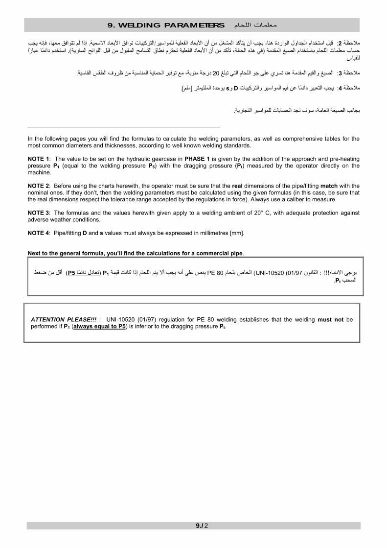
يعادل ضغط اللحام ( P1مقدمة باإلضافة إلى القرب وضغط التسخين المسبق رحلة األولىالمالقيمة التي سيتم ضبطها في علبة التروس الهيدروليكية في : مالحظةP5 ( مع ضغط السحب)Pt (الذي تم قياسه بواسطة المشغل مباشرة في الماآينة.
9. WELDING PARAMETERS معلمات اللحام
9./2
إذا لم تتوافق معها، فإنه يجب . األبعاد االسمية افقتوالترآيبات /للمواسير الفعليةقبل استخدام الجداول الواردة هنا، يجب أن يتأآد المشغل من أن األبعاد : 2مالحظة استخدم دائًما عياًرا ). في هذه الحالة، تأآد من أن األبعاد الفعلية تحترم نطاق التسامح المقبول من قبل اللوائح السارية(حساب معلمات اللحام باستخدام الصيغ المقدمة
.للقياس
.درجة مئوية، مع توفير الحماية المناسبة من ظروف الطقس القاسية 20ري على جو اللحام التي تبلغ الصيغ والقيم المقدمة هنا تس :3مالحظة
].ملم[بوحدة الملليمتر sو Dيجب التعبير دائًما عن قيم المواسير والترآيبات : 4مالحظة
. بجانب الصيغة العامة، سوف تجد الحسابات للمواسير التجارية
In the following pages you will find the formulas to calculate the welding parameters, as well as comprehensive tables for the most common diameters and thicknesses, according to well known welding standards. NOTE 1: The value to be set on the hydraulic gearcase in PHASE 1 is given by the addition of the approach and pre-heating pressure P1 (equal to the welding pressure P5) with the dragging pressure (Pt) measured by the operator directly on the machine. NOTE 2: Before using the charts herewith, the operator must be sure that the real dimensions of the pipe/fitting match with the nominal ones. If they don’t, then the welding parameters must be calculated using the given formulas (in this case, be sure that the real dimensions respect the tolerance range accepted by the regulations in force). Always use a caliber to measure. NOTE 3: The formulas and the values herewith given apply to a welding ambient of 20° C, with adequate protection against adverse weather conditions. NOTE 4: Pipe/fitting D and s values must always be expressed in millimetres [mm]. Next to the general formula, you’ll find the calculations for a commercial pipe.
من ضغط أقل )P5تعادل دائًما ( 1Pاللحام إذا آانت قيمة يجب أال يتمينص على أنه PE 80الخاص بلحام ) UNI-01/97) 10520القانون : !!!يرجى االنتباه .Ptالسحب
ATTENTION PLEASE!!! : UNI-10520 (01/97) regulation for PE 80 welding establishes that the welding must not be performed if P1 (always equal to P5) is inferior to the dragging pressure Pt.

9. WELDING PARAMETERS معلمات اللحام
9./3
)UNI 10520 (01/97): PE 80 (MRS 8 آيفية حساب معلمات اللحام وفًقا للقانون. 9.2
PE 80 (MRS 8) – UNI 10520 (01-97(
9.2. HOW TO CALCULATE THE WELDING PARAMETERS ACCORDING TO UNI 10520 (01/97): PE 80 (MRS 8)
PE 80 (MRS 8) – UNI 10520 (01-97)
درجة حرارة لوح التسخين
T = 210 عندما تكون قيمة درجات مئوية 10± درجة مئويةs ملم 12ملم و 0بين T = 200 عندما تكون قيمة درجات مئوية 10± درجة مئويةs ملم 12أعلى من
HEATING PLATE TEMPERATURE
T = 210° C ± 10° C when s is in between 0 mm and 12 mm T = 200° C ± 10° C when s is superior to 12 mm
االقتراب والتسخين المسبق: لمرحلة األولىا
PHASE 1: Approach and pre-heating
A = 0,5 + 0,1×s ]ملم [
Approach and pre-heating pressure
A = 0,5 + 0,1×s [mm] Bead width at the end of pre-heating
التسخين: المرحلة الثانية
الحد األقصى لضغط التسخين
t2 = 12 × s ]وقت التسخين ]ثانية
PHASE 2: Heating
Maximum heating pressure
t2 = 12 × s [sec] Heating time
P2 ] =بار[ P1 7,5
0,015 ×π ]بار[× P1 = (D - s) × s )5طالع الصفحة ] (2سم[الدفع اإلجمالي قسم
P2 = [bar] P1 7,5
0,015 × π Overall thrust section [cm2] (see page 5)
P1 = (D - s) × s × [bar]

9. WELDING PARAMETERS معلمات اللحام
9./4
فك لوح التسخين: المرحلة الثالثة
t3 = 4 + 0,3 × s ]أقصى وقت لفك لوح التسخين ]ثانية
PHASE 3: Removal of heating plate
t3 = 4 + 0,3 × s [sec] Maximum time to remove the heating plate
الوصول إلى ضغط اللحام: المرحلة الرابعة
t4 = 4 + 0.4 × s ]وقت الوصول إلى ضغط اللحام ]ثانية
PHASE 4: Reach of welding pressure
t4 = 4 + 0,4 × s [sec] Time to reach the welding pressure
اللحام: المرحلة الخامسة
P5 = P1 ]اللحامضغط ]بار
t5 = 3 + s ]وقت اللحام ]دقيقة
PHASE 5: Welding
P5 = P1 [bar] Welding pressure
t5 = 3 + s [min] Welding time

9. WELDING PARAMETERS معلمات اللحام
9./5
)UNI 10967 (10/01): PE 100 (MRS 10آيفية حساب معلمات اللحام وفًقا للقانون . 9.3 9.3. HOW TO CALCULATE THE WELDING PARAMETERS ACCORDING TO UNI 10967 (10/01): PE 100 (MRS 10)
PE 100 (MRS 10) – UNI 10967 (10/01( S ملم 20.0أقل من
درجة حرارة لوح التسخين
T = 215 درجة مئوية 5± درجة مئوية
PE 100 (MRS 10) – UNI 10967 (10/01) s inferior to 20,0 mm
HEATING PLATE TEMPERATURE
T = 215°C ± 5°C
ارجع إلى الفقرات . UNI 10520وفًقا للقانون ) PE 80 (MRS 8، مماثلة لتلك الوارد وصفها لـ )باستثناء درجة الحرارة(دورة اللحام وجميع المعلمات األخرى :التالية
The welding cycle and all other parameters (except for the temperature), are identical to the ones described for PE 80 (MRS 8) according to UNI 10520. Refer to the following paragraphs:
UNI 10520مثل المرحلة األولى من االقتراب والتسخين المسبق: المرحلة األولى االقتراب وضغط التسخين المسبق
عرض الخرز عند نهاية التسخين المسبق UNI 10520مثل المرحلة الثانية من التسخين: حلة الثانيةالمر
الحد األقصى لضغط التسخين وقت التسخين
UNI 10520مثل المرحلة الثالثة من فك لوح التسخين: المرحلة الثالثة أقصى وقت لفك لوح التسخين
UNI 10520مثل المرحلة الرابعة من الوصول إلى ضغط اللحام: المرحلة الرابعة وقت الوصول إلى ضغط اللحام
UNI 10520مثل المرحلة الخامسة من اللحام: المرحلة الخامسة ضغط اللحام وقت اللحام
UNI 10520مثل المرحلة السادسة من التبريد: المرحلة السادسة أدنى وقت للتبريد
PHASE 1: Approach and pre-heating As PHASE 1 of UNI 10520
Approach and pre-heating pressure
Bead width at the end of pre-heating
PHASE 2: Heating As PHASE 2 of UNI 10520
Maximum heating pressure
Heating time
PHASE 3: Removal of heating plate As PHASE 3 of UNI 10520
Maximum time to remove the heating plate
PHASE 4: Reach of welding pressure As PHASE 4 of UNI 10520
Time to reach the welding pressure
PHASE 5: Welding As PHASE 5 of UNI 10520
Welding pressure
Welding time
PHASE 6: Cooling As PHASE 6 of UNI 10520
Minimum cooling time
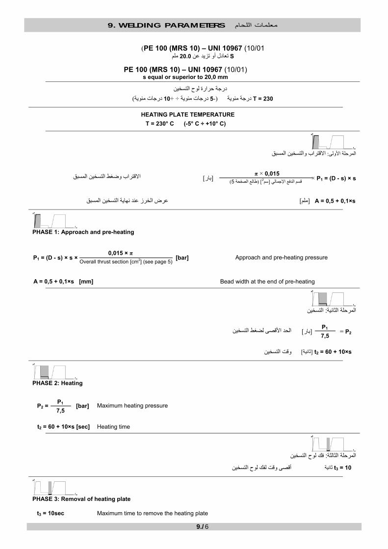
9. WELDING PARAMETERS معلمات اللحام
9./6
PE 100 (MRS 10) – UNI 10967 (10/01( S ملم 20.0تعادل أو تزيد عن
PE 100 (MRS 10) – UNI 10967 (10/01) s equal or superior to 20,0 mm
درجة حرارة لوح التسخين
T = 230 درجات مئوية 10+÷ درجات مئوية 5-(درجة مئوية(
HEATING PLATE TEMPERATURE
T = 230° C (-5° C ÷ +10° C)
االقتراب والتسخين المسبق: المرحلة األولى
االقتراب وضغط التسخين المسبق
A = 0,5 + 0,1×s ]عرض الخرز عند نهاية التسخين المسبق ]ملم
PHASE 1: Approach and pre-heating
Approach and pre-heating pressure
A = 0,5 + 0,1×s [mm] Bead width at the end of pre-heating
التسخين: المرحلة الثانية
الحد األقصى لضغط التسخين
t2 = 60 + 10×s ]وقت التسخين ]ثانية
PHASE 2: Heating
Maximum heating pressure
t2 = 60 + 10×s [sec] Heating time
فك لوح التسخين: المرحلة الثالثة
t3 = 10 أقصى وقت لفك لوح التسخين ثانية
PHASE 3: Removal of heating plate
t3 = 10sec Maximum time to remove the heating plate
P2 ] =بار[ P1 7,5
0,015 ×π )5طالع الصفحة ] (2سم[قسم الدفع اإلجمالي P1 = (D - s) × s × ]بار[
P2 = [bar] P1 7,5
0,015 × π Overall thrust section [cm2] (see page 5)
P1 = (D - s) × s × [bar]

9. WELDING PARAMETERS معلمات اللحام
9./7
الوصول إلى ضغط اللحام: المرحلة الرابعة
t4 = 10 وقت الوصول إلى ضغط اللحام ثانية
PHASE 4: Reach of welding pressure
t4 = 10 sec Time to reach the welding pressure
1وقت اللحام : المرحلة الخامسة
P5 = P1 ]5ضغط اللحام ]بار
t5 = 10 5وقت اللحام ثانية
PHASE 5: Welding TIME 1
P5 = P1 [bar] Welding pressure 5
t5 = 10sec Welding time 5
2وقت اللحام : المرحلة السادسة
6ضغط اللحام
t6 = 3 + s ]6وقت اللحام ]دقيقة
PHASE 6: Welding TIME 2
Welding pressure 6
t6 = 3 + s [min] Welding time 6
التبريد: المرحلة السابعة
t7 = 1,5 × s ]أدنى وقت للتبريد ]دقيقة
PHASE 7: Cooling
t7 = 1,5 × s [min] Minimum cooling time
P1
3P6] =بار[
P1
3 P6 = [bar]

9. WELDING PARAMETERS معلمات اللحام
9./8
DVS 2207-1: HDPE حام وفًقا لـ آيفية حساب معلمات الل. 9.4 9.4. HOW TO CALCULATE THE WELDING PARAMETERS ACCORDING TO DVS 2207-1: HDPE
PE-HD DVS 2207-1 (08/95(
درجة حرارة لوح التسخين
PE-HD DVS 2207-1 (08/95)
HEATING PLATE TEMPERATURE
االقتراب والتسخين المسبق: المرحلة األولى
االقتراب وضغط التسخين المسبق
ارتفاع الخرز عند نهاية التسخين المسبق
PHASE 1: Approach and pre-heating
Approach and pre-heating pressure
0,015 ×π ]بار[ × P1 = (D - s) × s )5طالع الصفحة ] (2سم[قسم الدفع اإلجمالي
S=spessore
S =السمك
s ]ملم[ الترآيبة/الماسورة
االرتفاعA ]ملم[
4.50,5ما يصل إلى 4,5 …71,0
7 …121,5 12 …192,0 19 …262,5 26 …373,0 37 …503,5 50704 0

9. WELDING PARAMETERS معلمات اللحام
9./9
Bead height at the end of pre-heating
التسخين :المرحلة الثانية
الحد األقصى لضغط التسخين
P2 ] =بار[
وقت التسخين
PHASE 2: Heating
Maximum heating pressure
P2 = [bar]
Heating time
0,015 × π Overall thrust section [cm2] (see page 5)
P1 = (D - s) × s × [bar]
P1
7,5
s [mm] Pipe/fitting
HeightA [mm]
up to 4,5 0,54,5 … 7 1,07 … 12 1,5
12 … 19 2,019 … 26 2,526 … 37 3,037 … 50 3,550 … 70 4,0
s [mm] Pipe/fitting t2 [sec]
up to 4,5 up to 454,5 … 7 45 … 707 … 12 70 … 120
12 … 19 120 … 19019 … 26 190 … 26026 … 37 260 … 37037 … 50 370 … 50050 … 70 500 … 700
P1
7,5
s ]ملم[ ]ثانية[ t2 الترآيبة/الماسورة
45ما يصل إلى 4.5يصل إلى ما4,5 …745 …70
7 …1270 …120 12 …19120 …190 19 …26190 …260 26 …37260 …370 37 …50370 …500
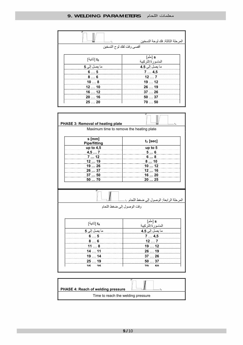
9. WELDING PARAMETERS معلمات اللحام
9./10
فك لوحة التسخين: لثالثةالمرحلة ا أقصى وقت لفك لوح التسخين
PHASE 3: Removal of heating plate Maximum time to remove the heating plate
الوصول إلى ضغط اللحام: المرحلة الرابعة
وقت الوصول إلى ضغط اللحام
PHASE 4: Reach of welding pressure
Time to reach the welding pressure
s [mm] Pipe/fitting t3 [sec]
up to 4,5 up to 54,5 … 7 5 … 67 … 12 6 … 8
12 … 19 8 … 1019 … 26 10 … 1226 … 37 12 … 1637 … 50 16 … 2050 … 70 20 … 25
s ]ملم[ ]ثانية[ t3 الترآيبة/الماسورة
5ما يصل إلى 4.5ما يصل إلى 4,5 …75 …6
7 …126 …8 12 …198 …10 19 …2610 …12 26 …3712 …16 37 …5016 …20 50…7020 …25
s ]ملم[ ]ثانية[ t4 الترآيبة/الماسورة
5ما يصل إلى 4.5ما يصل إلى 4,5 …75 …6
7 …126 …8 12 …198 …11 19 …2611 …14 26 …3714 …19 37 …5019 …25 50702535

9. WELDING PARAMETERS معلمات اللحام
9./11
اللحام :المرحلة الخامسة ضغط اللحام
P5 = P1 ]بار[
وقت اللحام
PHASE 5: Welding Welding pressure
P5 = P1 [bar]
Welding time
s [mm] Pipe/fitting t4 [sec]
up to 4,5 up to 54,5 … 7 5 … 67 … 12 6 … 8
12 … 19 8 … 1119 … 26 11 … 1426 … 37 14 … 1937 … 50 19 … 2550 … 70 25 … 35
s [mm] Pipe/fitting t5 [min]
up to 4,5 up to 64,5 … 7 6 … 107 … 12 10 … 1612 … 19 16 … 2419 … 26 24 … 3226 … 37 32 … 4537 … 50 45 … 6050 … 70 60 … 80
s ]ملم[ ]دقيقة[ t5 الترآيبة/الماسورة
6ما يصل إلى 4.5ما يصل إلى 4,5 …76 …10
7 …1210 …16 12 …1916 …24 19 …2624 …32 26 …3732 …45 37 …5045 …60 50…7060 …80

9. WELDING PARAMETERS معلمات اللحام
9./12
DVS 2207 – 11 (02/99): PP آيفية حساب معلمات اللحام وفًقا لـ . 9.5 9.5. HOW TO CALCULATE THE WELDING PARAMETERS ACCORDING TO DVS 2207 – 11 (02/99): PP
PP – DVS 2207–11 (02/99(
درجة حرارة لوح التسخين درجة الحرارة التي سيتم إعدادها في المنظم الحراري
T = 210 درجات مئوية 10± درجة مئوية
PP – DVS 2207–11 (02/99)
HEATING PLATE TEMPERATURE Temperature to be set on the thermoregulator
T = 210°C ± 10°C
االقتراب والتسخين المسبق: المرحلة األولى
االقتراب وضغط التسخين المسبق
ارتفاع الخرز عند نهاية التسخين المسبق
PHASE 1: Approach and pre-heating
Approach and pre-heating pressure
Bead height at the end of pre-heating
0.010 ×π ]بار[× P1 = (D - s) × s )5طالع الصفحة ] (2سم[قسم الدفع اإلجمالي
0,010 × π Overall thrust section [cm2] (see page 5)
P1 = (D - s) × s × [bar]
s ]ملم[ الترآيبة/الماسورة
االرتفاعA ]ملم[
4.50,5ما يصل إلى 4,5 …70,5
7 …121,0 12 …191,0 19 …261,5 26 …372,0 37 …502,5
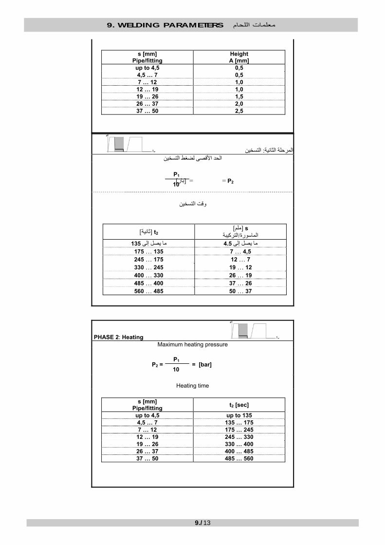
9. WELDING PARAMETERS معلمات اللحام
9./13
التسخين :المرحلة الثانية الحد األقصى لضغط التسخين
P2 ] = =بار[
وقت التسخين
PHASE 2: Heating Maximum heating pressure
P2 = = [bar]
Heating time
s [mm] Pipe/fitting
HeightA [mm]
up to 4,5 0,54,5 … 7 0,57 … 12 1,0
12 … 19 1,019 … 26 1,526 … 37 2,037 … 50 2,5
P1
10
s [mm] Pipe/fitting t2 [sec]
up to 4,5 up to 1354,5 … 7 135 … 1757 … 12 175 … 245
12 … 19 245 … 33019 … 26 330 … 40026 … 37 400 … 48537 … 50 485 … 560
P1
10
s ]ملم[ ]ثانية[ t2 ةالترآيب/الماسورة
135ما يصل إلى 4.5ما يصل إلى 4,5 …7135 …175
7 …12175 …245 12 …19245 …330 19 …26330 …400 26 …37400 …485 37 …50485 …560

9. WELDING PARAMETERS معلمات اللحام
9./14
فك لوحة التسخين: المرحلة الثالثة
أقصى وقت لفك لوح التسخين
PHASE 3: Removal of heating plate
Maximum time to remove the heating plate
الوصول إلى ضغط اللحام: المرحلة الرابعة
وقت الوصول إلى ضغط اللحام
PHASE 4: Reach of welding pressure
Time to reach the welding pressure
s [mm] Pipe/fitting t3 [sec]
up to 4,5 up to 54,5 … 7 5 …67 … 12 6 … 7
12 … 19 7 … 919 … 26 9 … 1126 … 37 11 … 1437 … 50 14 … 17
s ]ملم[ ]ثانية[ t3 الترآيبة/الماسورة
5ما يصل إلى 4.5ما يصل إلى 4,5 …75 …6
7 …126 …7 12 …197 …9 19 …269 …11 26 …3711 …14 37 …5014 …17
s ]ملم[ ]ثانية[ t4 الترآيبة/الماسورة
6ما يصل إلى 4.5ما يصل إلى 4,5 …76 …7
7 …127 …11 12 …1911 …17 19 …2617 …22 26 …3722 …32 37 …5032 …43

9. WELDING PARAMETERS معلمات اللحام
9./15
لحامال :المرحلة الخامسة
ضغط اللحام P5 = P1 ]بار[
وقت اللحام
PHASE 5: Welding
Welding pressure
P5 = P1 [bar]
Welding time
s [mm] Pipe/fitting t4 [sec]
up to 4,5 up to 64,5 … 7 6 … 77 … 12 7 … 11
12 … 19 11 … 1719 … 26 17 … 2226 … 37 22 … 3237 … 50 32 … 43
s [mm] Pipe/fitting t5 [min]
up to 4,5 up to 64,5 … 7 6 … 127 … 12 12 … 20
12 … 19 20 … 3019 … 26 30 … 4026 … 37 40 … 5537 … 50 55 … 70
s ]ملم[ ]دقيقة[ t5 بةالترآي/الماسورة
6ما يصل إلى 4.5ما يصل إلى 4,5 …76 …12
7 …1212 …20 12 …1920 …30 19 …2630 …40 26 …3740 …55 37 …5055 …70
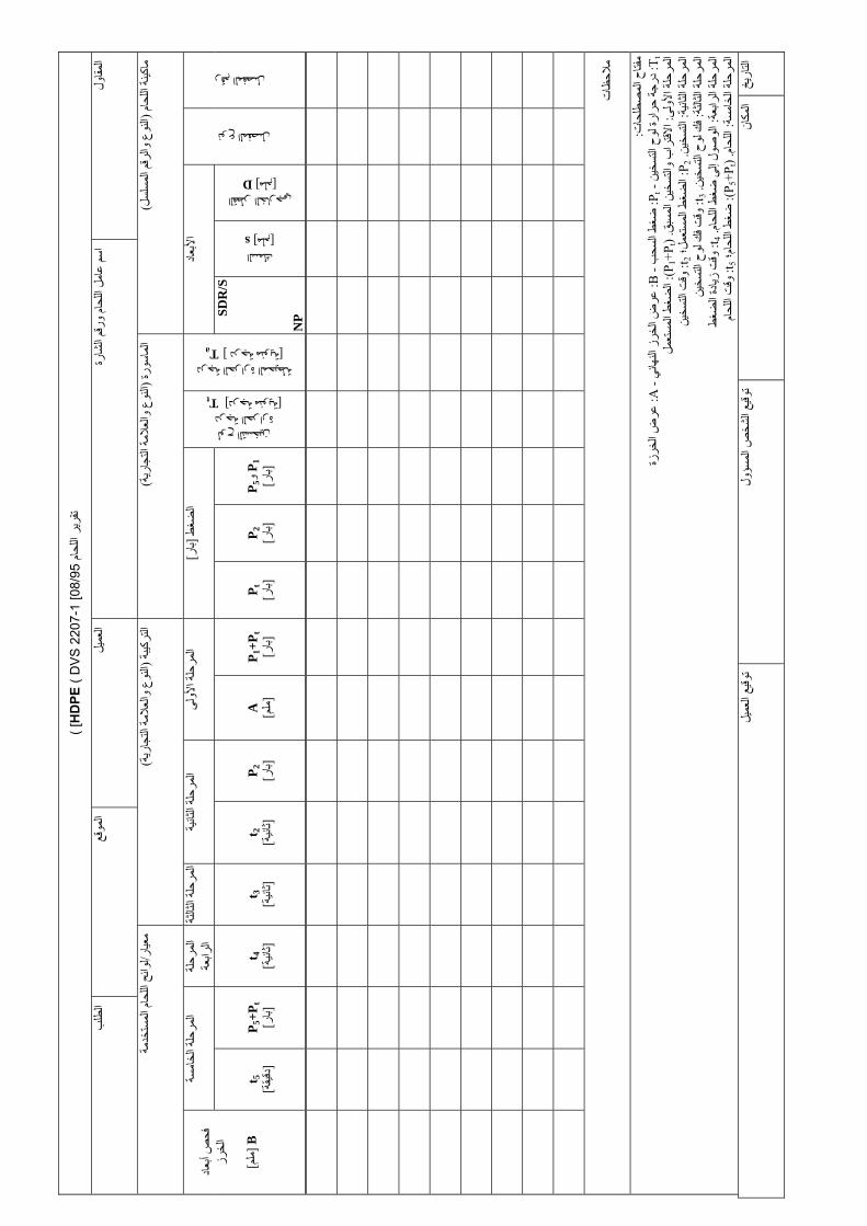
ام لح اليرقرت
HD
PE (
DV
S 2
207-
1 [0
8/95
( [
ولمقاال
رةشا الرقم وحام اللملعا
سم ا
يلعمال
قعموال
بطلال
ام لح الينةماآ
)سلسلالم
قم لر واوعالن
(رة سولماا
)ريةجاالت
مة عالوال
ع نوال
(بة رآيالت
)ريةجاالت
مة عالوال
ع نوال
(ارمعي
/مةخدستالم
ام لح الئحلوا
رقم المفصل
نوع المفصل
عادألبا
درجة الحرارة المحيطة Ta ] درجة مئوية [
لوح التسخين درجة الحرارة
Tt ] درجة مئوية [
ط ضغ
ال]
ارب
[ لىألوة احلمرال
نيةلثاة احلمرال
لثةلثاة احلمرال
لة رحالم
عةرابال
سةخام
الحلةمرال
اد أبع
ص فح
رزلخا
B ] ]ملم
القطر الخارجي D ] ملم [
السمك s ] ملم [
SDR
/S
N
P
P و 1P 5
]ارب
[ P 2
]ارب
[ P t
]ارب
[ P 1
+Pt
]
ارب
[ A
] ]ملم
P 2 ]
ارب
[ t 2
]نيةثا
[ t 3
]نيةثا
[ t 4
]نيةثا
[ P 5
+Pt
]
ارب
[ t 5
]يقةدق
[
تظاالحم
تحاطلصالم
ح فتام
: T t :
ن خيتس الوحة لارحر
جة در
- P t :
ب سح الغطض
- B :
ي هائالن
ز خر الضعر
- A :
زة خر الضعر
لىألوة احلمرال
:بقمس الينسخالت وبراالقتا
) .P 1
+Pt
:(ملستع
المط ضغ
ال
انيالث
لة رحالم
: ةينسخالت
.P 2 :
ل؛ عمستالم
ط ضغ
الt 2 :
ينسخ التتوق
لثةلثاة احلمرال
:ينسخالت
ح لوفك
.t 3 :ينسخالت
ح لوفك
ت وق
عةراب الحلةمرال
:حام اللغطض
ى إلولصالو
.t 4 :غطض الادةزي
ت وق
سةخام
الحلةمرال
:حامالل
) .P 5
+Pt
:(م؛ حا اللغطض
t 5 :حام اللتوق
يخارالت
انمكال
ص ا
شخ اليعوقت
ولسؤلم
يلعم اليعوقت

WELD
ING
REPO
RT H
DPE ( D
VS
2207-1 [08/95] )
Contractor
Welder’s nam
e & badge #
C
ustomer
Site O
rder
Welding m
achine (type & serial #)
Pipe (type & tradem
ark) Fitting (type &
trademark)
Welding standard/regulation used
Joint #
Joint type
Dim
ensions
Ambient temperature
Ta [ °C]
Heating plate Temperature
Tt [ ° C]
Pressure [bar]Phase 1
Phase 2Phase 3
Phase 4Phase 5
B
ead dim
ension check
B
[mm
]
Outside diameter D [mm]
Thickness s [mm]
SDR
/S
NP
P1 &
P5
[bar] P
2 [bar]
Pt
[bar] P
1 +Pt
[bar] A
[m
m]
P2
[bar] t2
[sec] t3
[sec] t4
[sec] P
5 +Pt
[bar] t5
[min]
Notes
Legend:
Tt : H
eating plate temperature – P
t : Dragging pressure – B
: Final bead width – A
: Bead w
idth Phase 1: A
pproach and pre-heating. (P1 +P
t ): Applied pressure
Phase 2: Heating. P
2 : Applied pressure; t2 : H
eating time
Phase 3: Rem
oval of heating plate. t3 : Time to rem
ove the heating plate Phase 4: R
each of welding pressure. t4 : Tim
e to increase pressure Phase 5: W
elding. (P5 +P
t ): Welding pressure; t5 : W
elding time
Date
Place Signature of person in charge
Signature of customer

ام لح اليرقرت
PP (
DV
S 2
207-
11 [0
2/99
( [
ولمقاال
رةشا الرقم وحام اللملعا
سم ا
يلعمال
قعموال
بطلال
ام لح الينةماآ
)سلسلالم
قم لر واوعالن
(رة سولماا
)ريةجاالت
مة عالوال
ع نوال
(بة رآيالت
)ريةجاالت
مة عالوال
ع نوال
(ارمعي
/مةخدستالم
ام لح الئحلوا
رقم ال مفصل
نوع المفصل
عادألبا
درجة الحرارة المحيطة Ta ] درجة مئوية [
لوح التسخين درجة الحرارة
Tt ] درجة مئوية [
ط ضغ
ال]
ارب
[ لىألوة احلمرال
نيةلثاة احلمرال
لثةلثاة احلمرال
لة رحالم
عةرابال
سةخام
الحلةمرال
اد أبع
ص فح
رزلخا
B ] ]ملم
القطر الخارجي D ] ملم [
السمك s ] ملم [
SDR
/S
N
P
P و 1P 5
]ارب
[ P 2
]ارب
[ P t
]ارب
[ P 1
+Pt
]
ارب
[ A
] ]ملم
P 2 ]
ارب
[ t 2
]نيةثا
[ t 3
]نيةثا
[ t 4
]نيةثا
[ P 5
+Pt
]
ارب
[ t 5
]يقةدق
[
تظاالحم
تحاطلصالم
ح فتام
: T t :
ن خيتس الوحة لارحر
جة در
- P t :
ب سح الغطض
- B :
ي هائالن
ز خر الضعر
- A :
زة خر الضعر
لىألوة احلمرال
:بقمس الينسخالت وبراالقتا
) .P 1
+Pt
:(ملستع
المط ضغ
ال
حلمرال
نيةلثاة ا
:ينسخالت
.P 2 :
ل؛ عمستالم
ط ضغ
الt 2 :
ينسخ التتوق
لثةلثاة احلمرال
:ينسخالت
ح لوفك
.t 3 :ينسخالت
ح لوفك
ت وق
عةراب الحلةمرال
:حام اللغطض
ى إلولصالو
.t 4 :غطض الادةزي
ت وق
سةخام
الحلةمرال
:حامالل
) .P 5
+Pt
:(م؛ حا اللغطض
t 5 :حام اللتوق
يخارالت
انمكال
يعوقت
ولسؤالم
ص شخال
يلعم اليعوقت

WELD
ING
REPO
RT PP ( D
VS
2207-11 [02/99] ) C
ontractor
Welder’s nam
e & badge #
C
ustomer
Site O
rder
Welding m
achine (type & serial #)
Pipe (type & tradem
ark) Fitting (type &
trademark)
Welding standard/regulation used
Joint #
Joint type
Dim
ensions
Ambient temperature
Ta [ °C] Heating plate Temperature
Tt [ ° C]
Pressure [bar]Phase 1
Phase 2Phase 3
Phase 4Phase 5
B
ead dim
ension check
B
[mm
]
Outside diameter D [mm]
Thickness s [mm]
SDR
/S N
P
P1 &
P5
[bar] P
2 [bar]
Pt
[bar] P
1 +Pt
[bar] A
[m
m]
P2
[bar] t2
[sec] t3
[sec] t4
[sec] P
5 +Pt
[bar] t5
[min]
Notes
Legend:
Tt : H
eating plate temperature – P
t : Dragging pressure – B
: Final bead width – A
: Bead w
idth Phase 1: A
pproach and pre-heating. (P1 +P
t ): Applied pressure
Phase 2: Heating. P
2 : Applied pressure; t2 : H
eating time
Phase 3: Rem
oval of heating plate. t3 : Time to rem
ove the heating plate Phase 4: R
each of welding pressure. t4 : Tim
e to increase pressure Phase 5: W
elding. (P5 +P
t ): Welding pressure; t5 : W
elding time
Date
Place Signature of person in charge
Signature of customer

DICHIARAZIONE DI CONFORMITÀ CONFORMITY DECLARATION DECLARACION DE CONFORMIDAD DECLARAÇÃO DE CONFORMIDADE KONFORMITÄTSERKLÄRUNG
Ritmo S.p.A. Via A. Volta, 7 - Z.I. Selve - 35037 Bresseo di Teolo (PD) - ITALIA
Tel. ++39-(0)49-9901888 Fax ++39-(0)49-9901993
Dichiara che il prodotto di sua produzione di seguito identificato:
Declares that the product of its our production named as follows:
Declara que los productos identificados mas abajo:
Declara que as seguintes soldadoras (de sua produção):
Erklärt daß das Produkt von unserer Produktion wie folgt identifiziert ist:
BASIC 160V1 BASIC 200V0 BASIC 250V1 BASIC 315 V1 BASIC 355V0
è conforme alle disposizioni delle seguenti Direttive:
is made in compliance with the following directives:
está conforme con lo dispuesto:
respeitam quanto indicado nas seguintes Directivas e Normativas:
gemäß den geltenden gesetzlichen Richtlinien:
2006/42/CE 2004/108/CE 2006/95/CE UNI EN ISO 12100-1 :2005 UNI EN ISO 12100-2 :2005 CEI 44-5
La presente dichiarazione perde ogni validità in caso di modifiche apportate al prodotto non approvate esplicitamente e per iscritto dal costruttore.
This declaration becomes null and void in the event of any changes being made to the product without the written and explicit manufacturer’s approval.
Esta declaración no es válida en caso de aportar modificaciones a los productos sin la expresa autorización escrita del fabricante.
Qualquer modificação efectuada ao aparelho, que não tenha sido autorizada a priori em modo explícito e por escrito pelo fabricante, anula a presente declaração.
Die Gültigkeit der vorliegenden Erklärung ist nichtig im Falle von Änderungen des Gerätes, die nicht ausdrücklich schriftlich vom Hersteller genehmigt wurden.
Bresseo di Teolo, 26/01/10
( Renzo Bortoli ): __________________________________
Firma / Signature / Unterschrift / Firma/Assinatura
D
P
E
GB
I
P
P
P
D
E
GB
I
D
E
GB
I
E
D
GB
I

ATTENZIONE! / ATTENTION!
La macchina indicata in questo manuale deve essere sottoposta ad una revisione completa almeno ogni due anni (o più frequentemente, se la normativa nazionale così lo richiede). La revisione può essere eseguita soltanto dal fabbricante o da un centro assistenza autorizzato dallo stesso.
In nessun caso potrà la Ritmo S.p.A. essere tenuta responsabile per danni diretti, indiretti, accidentali o consequenziali, derivanti dall’utilizzo di una macchina non revisionata.
In nessun caso potrà la Ritmo S.p.A. essere tenuta responsabile per danni diretti, indiretti, accidentali o consequenziali, derivanti da uno scorretto utilizzo della macchina (cioè, senza rispettarle istruzioni di questo manuale).
The machine herein indicated must undergo inspection and overhaul at least once every two years – or more frequently, if the national regulation so requires. The inspection and overhaul must be performed by the manufacturer or an authorized service centre, only.
In no event shall Ritmo S.p.A. be liable for any direct, indirect, incidental, or consequential damages of any kind whatsoever with respect to the use of a machine that did not undergo regular maintenance/overhaul.
In no event shall Ritmo S.p.A. be liable for any direct, indirect, incidental, or consequential damages of any kind whatsoever with respect to an improper use (i.e., not according to the instructions herein give) of the machine.
La machine indiquée dans ce manuel doit être soumise à une révision complète au moins tous deux années auprès la Ritmo S.p.A. ou auprès d’un centre d’assistance autorisé (par écrit) par Ritmo S.p.A.. La machine doit être livrée avec le respectif livret de révisions.
En aucun cas ne peut Ritmo S.p.A. être tenue pour responsable des éventuels dommages directs, indirects, accidentels ou consequentiels résultants de l’utilisation d’une machine qui n’a pas été révisée.
En aucun cas ne peut Ritmo S.p.A. être tenue pour responsable des éventuels dommages directs, indirects, accidentels ou consequentiels résultants d’une utilisation incorrecte (c’est-à-dire, sans respecter les instructions données dans ce manuel).
In jedem Fall muss das Schweissgerät zumindest alle zwei Jahre einer Revision beim Hersteller oder beim Kundendienst unterzogen werden.
Ritmo S.p.A. ist nicht verantwortlich für direkte, indirekte, Beschädigung durch unsachgemässe Handhabung bei Maschinen ohne Wartung sowie Missachtung der Betriebsvorschriften.
A máquina deve ser enviada à revisão pelo menos uma vez cada dois anos (ou mais frequentemente, se a normativa nacional assim o exigir). A revisão só pode ser feita pelo fabricante ou por um centro de assistência autorizado pelo mesmo.
Em nenhum caso poderá a Ritmo S.p.A. ser responsável por danos directos, indirectos, acidentais ou consequenciais inerentes à utilização de uma máquina que não efectuou a revisão bianual.
Em nenhum caso poderá a Ritmo S.p.A. ser responsável por danos directos, indirectos, acidentais ou consequenciais inerentes a uma incorrecta utilização da máquina (i.e., não de acordo com as instruções dadas neste manual).
La máquina que se describe en este manual debe someterse a una revisión técnica al menos una vez cada dos años (o con más frecuencia, si la normativa nacional así lo requiere). La revisión debe ser realizada únicamente por el fabricante o por un centro de asistencia técnica por él autorizado. En ningún caso Ritmo S.p.A. será responsable por daños directos, indirectos, incidentales o consecuentes daños y perjuicios de cualquier naturaleza causados por la utilización de una máquina que no es sometida a su revisión técnica periódica. En ningún caso Ritmo S.p.A. será responsable por daños directos, indirectos, incidentales o consecuentes daños y perjuicios de cualquier naturaleza debido al uso incorrecto (es decir, no respetando las instrucciones detalladas en este manual) de la máquina.
E
P
D
F
GB
I