
Risk Assessment No 4 - Risk Assessment for the Use of RISO ...
15
Page 1 Risk Assessment No 4 - Risk Assessment for the Use of RISO DA-15 and DA-20 OSL Ionising Radiations Regulations 2017 Document type Procedure Scope (applies to) Staff and students Applicability date 11/07/2021 Review / Expiry date 12/07/2024 Approved date 12/07/2021 Approver Head of EHSS Document owner Deputy Director School / unit Environmental Health and Safety Services Document status Published Information classification Public Equality impact assessment None Key terms Health and safety/Hazard identification and risk assessment Purpose Compliance with Ionising Radiations Regulations 2017 legislation
Transcript of Risk Assessment No 4 - Risk Assessment for the Use of RISO ...

Page 1
Risk Assessment No 4 -
Risk Assessment for the Use of RISO DA-15 and
DA-20 OSL
Ionising Radiations Regulations 2017
Document type Procedure
Scope (applies to) Staff and students
Applicability date 11/07/2021
Review / Expiry date 12/07/2024
Approved date 12/07/2021
Approver Head of EHSS
Document owner Deputy Director
School / unit Environmental Health and Safety Services
Document status Published
Information classification Public
Equality impact assessment None
Key terms Health and safety/Hazard identification and risk assessment
Purpose Compliance with Ionising Radiations Regulations 2017 legislation

Page 2
RISK ASSESSMENT 4 - Use of RISO DA-15 and DA-20 – IRR17
Location of Equipment (Building and Room Number)
Irvine Building - Room Number
Description of Work and Scope of the Assessment
Use of Risø DA-15 and DA-20 OSL/TL readers for luminescence measurements
This risk assessment has been carried out in accordance with the Ionising
Radiations Regulations 2017 (IRR17) Approved Code of Practice (ACoP). This risk
assessment only addresses the radiological risks associated with the type of
equipment detailed above.
Who is at risk?
The operator and other workers in the laboratory
ACoP Paragraph 70 - Matters to be considered in an assessment, where relevant
70(a) - Nature of the radiation sources likely to be present
Risø 1 (A Risø OSL/TL-DA-15 system (instrument no. 63), connected to a controller model
DA-20): 90Sr/90Y, source strength 1.48GBq
Risø 2 (A Risø TL/OSL-DA-20 system (instrument no. 219), connected to a controller
model DA-20): 90Sr/90Y, source strength 1.48GBq
Risø 3 (A Risø TL/OSL-DA-15 system (instrument no. 116), connected to a controller
model DA-20): 90Sr/90Y, source strength 1.48GBq
70(b) - Estimated dose rates
External – external dose rate originates entirely from bremsstrahlung due to interaction of
beta particles in the shielding materials. When source is not activated, dose rate at
distance of 1 m from the front of the Risø reader is <0.2µSv/h; when source is activated,
dose rate is <0.3µSv/h. The dose rate directly on the surface of the irradiator is < 5μSv/h
both when the source is activated and not activated. Further details in Appendix 1
Internal - dose rate to quartz at sample position is approximately 0.1 Gy/s.
70(c) - Likelihood of contamination arising and being spread
None
70(d) - Results of previous personal dosimetry and area monitoring

Page 3
see appendix 1
70(e) - Advice from manufacturers or suppliers about safe use and maintenance of
equipment
Only trained and experienced workers (or inexperienced workers under close personal
supervision by an experienced trained worker) allowed into the area where this work is
undertaken.
The Risø reader should be positioned in such a way that the space underneath the reader
is inaccessible, and that the worker is prevented from using the space to the left of the
reader.
All workers must wear a whole body dosimeter badge when entering this area.
70(f) - Engineering Controls, etc. In place or planned
The Risø irradiator is made of brass (outer diameter 10cm, height 9.5cm) and is surrounded by 20 mm of lead on the sides, and 40 mm on the top. An aluminium safety helmet (outer diameter 222 mm) covers the entire irradiator and lead shielding. The source is securely placed inside the irradiator, and backed by a 20 mm thick aluminium spacer, a 20 mm thick lead spacer, a spring washer, and final, 25 mm thick aluminium spacer (see Figure 8). The source is mounted inside a rotating aluminium wheel which is pneumatically activated. When the source is ‘off’ - the default position - it points directly upwards directly at a 10 mm thick carbon absorber (diameter 18.3 mm) completely covering the emitting surface. When the source is ‘on’ – the activated position - it points downwards towards the measurement chamber. A 0.125 mm beryllium window is located between the irradiator and the measurement chamber to act as vacuum interface for the measurement chamber.
Further safety controls:
Hardware: 1.) lid operation not possible when source is activated; 2.) source will not
activate if lid is open, or partly open; 3.) if compressed air is not present, no software
controlled irradiations are allowed
Software: 1.) disables irradiation if not gas supplied: this prevents the accidental activation
of the source by a failed gas supply; 2.) if air supply valve fails such that compressed air is
delivered directly to the actuator, the Controller recognises no request for irradiation was
sent and sends deactivation command. In the second scenario the lid locks, and there is
no danger to the operator.
70(g) - Planned Systems of Work
Only trained and experienced workers (or inexperienced workers under close personal
supervision by an experienced trained worker) allowed into the area where this work is
undertaken.
Local rules apply in the laboratory.
In the event of malfunction of the irradiator, i.e. if the irradiator behaves unusually or
there is any suggestion of improper operation, the user must stop using the equipment

Page 4
immediately, evacuate the immediate area and request the assistance of a qualified
radiation expert with appropriate medical and dosimetric monitoring
70(h) - Estimated airborne and surface contamination levels
None
70(i) - Effectiveness and suitability of PPE
Laboratory coat
70(j) - Unrestricted access to high dose rates or significant contamination
Not allowed. Only trained and experienced workers (or inexperienced workers under close
personal supervision by an experienced trained worker). All workers exit the room when
Risø readers are running.
70(k) - Possible accident situations, their likelihood and severity
See Table 1
70(l) - Consequences of failure of Control Measures including Systems of Work
See Appendix 2
70(m) - Steps taken to prevent accidents, or limit their consequences
See Table 1.

Page 5
TABLE 1: Personal
Step
Who is Affected
Hazard Initial Risk Controls Residual Risk
Description Effect SF FF R List of Controls Required SF FF R
1
Instrument operator
External radiation dose from sealed 90Sr/90Y source within Risø reader
Possibility of raising risk of some form of cancer.
2 2 4 The 90Sr/90Y sources are well shielded within the Risø readers The Risø readers have both hardware and software safety controls to prevent accidental activation of the source Strict adherence to Local Rules required use of Risø readers Follow the ALARA-principle, which states that all doses shall be kept as low as reasonably achievable
2 1 2
2 Laboratory workers
External radiation dose from sealed 90Sr/90Y source within Risø reader
Possibility of raising risk of some form of cancer.
2 2 4
Only trained and experienced workers (or inexperienced workers under close personal supervision by an experienced trained worker)
2 1 2
3 Estates / Trades
External radiation dose from sealed 90Sr/90Y source within Risø reader
Possibility of raising risk of some form of cancer.
2 2 4 Estates / Tradesmen only permitted access under close supervision by either the DRPS or LRPS
1 1 1
4 Administrative staff
External radiation dose from sealed 90Sr/90Y source within Risø reader
Possibility of raising risk of some form of cancer.
2 2 4 No need for administrative staff to access luminescence laboratories. Should access be required, it would only be permitted under close supervision by either the DRPS or LRPS
1 1 1

Page 6
5 Cleaners External radiation dose from sealed 90Sr/90Y source within Risø reader
Possibility of raising risk of some form of cancer.
2 2 4 No cleaners are permitted access to the luminescence laboratories
1 1 1

Page 7

Page 8
ACoP Paragraph 71 – Outcomes of the assessment
71(a) - Actions taken to keep exposures ALARP
All users to be trained by DRPS and Lab-PI, Dr Tim Kinnaird or LPRS, Dr Aayush
Srivastava
71(b) - What Engineering Controls, Warning Signals and other Safety Systems are
necessary
Access to luminescence laboratories restricted to trained and experienced workers. The
luminescence laboratories remained locked at all times: key holders are the DRPS and
LPRS. A key is stored at reception for emergencies: either the DRPS or LPRS must be
notified prior to access.
All workers instructed on the Local Laboratory Rules.
71(c) - Whether PPE is appropriate and if so what type
Laboratory coat
71(d) - Dose Constraints
An investigation action level 0f 0.5 mSv/2 months has been adopted.
71(e) - Protection of female employees
No special protection required. A separate specialised risk assessment will be
undertaken for each expectant mother who wishes to continue working with the Risø
readers.
71(f) - Investigation levels
An investigation action level of 0.5 mSv/2 months has been adopted.
71(g) - Maintenance and testing schedules
There will be 2 yearly audit of premises
The University of St Andrews is a charity registered in Scotland, No: SC013532
71(h) - Contingency Plans
As identified in Local Rules.
71(i) - Training needs
All workers must follow the Local Rules and have received specific induction training to
the Risø readers before use
71(j) - Designation of Controlled and Supervised Areas
The Risø Room (annex of room 207) is a Supervised Area
71(k) - Access restrictions and other precautions for designated areas
Access to the laboratories will be via a lock on the entrance to the room
71(l) - Designation of persons
Not required.
71(m) - Personal dosimetry
Whole body dosimeter badges issued to workers.
71(n) - Leak testing of radioactive sources
The sources are leak tested at least every 2 years.
71(o) - Responsibilities of managers
Ensure that Local Rules are followed, and all staff are properly trained
71(p) – Monitoring / auditing program to ensure compliance with IRR77
URPA to audit operations every two years
The University of St Andrews is a charity registered in Scotland, No: SC013532
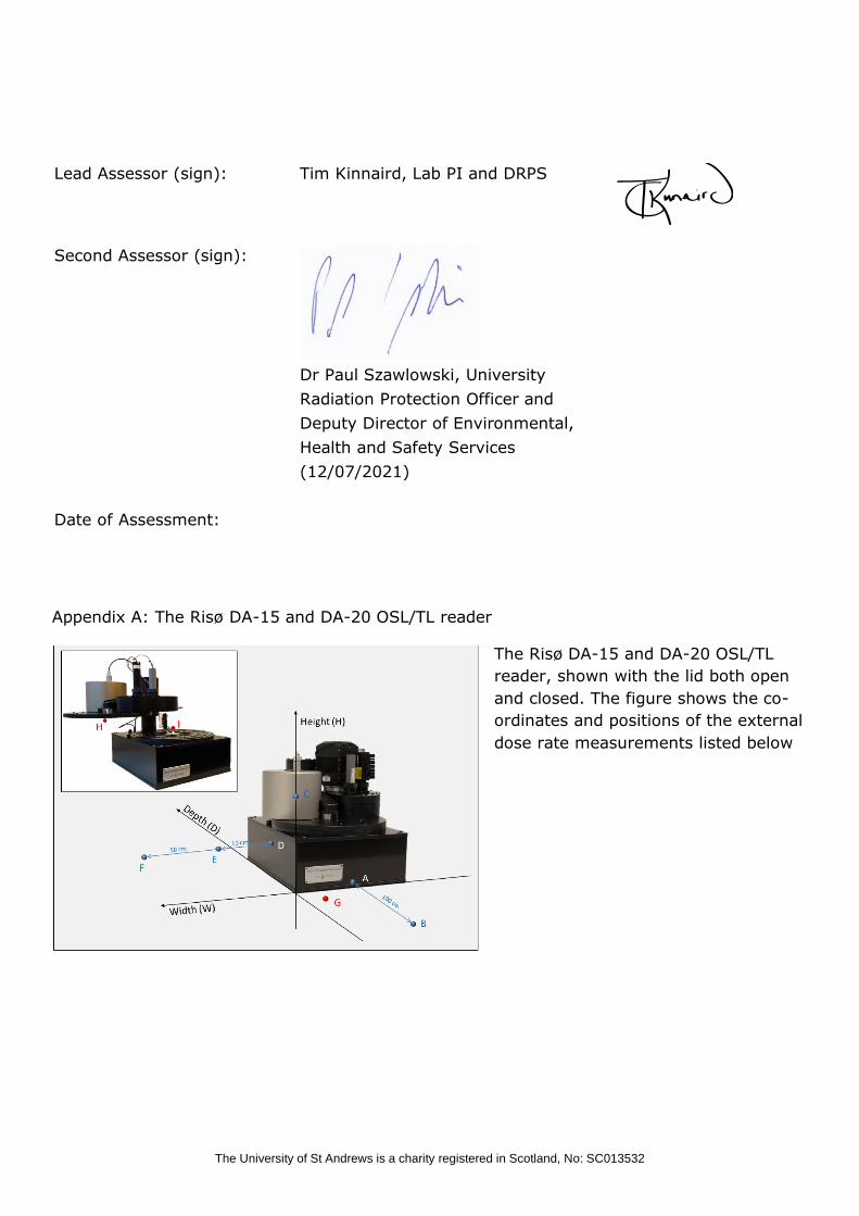
Appendix A: The Risø DA-15 and DA-20 OSL/TL reader
The Risø DA-15 and DA-20 OSL/TL
reader, shown with the lid both open
and closed. The figure shows the co-
ordinates and positions of the external
dose rate measurements listed below
Lead Assessor (sign): Tim Kinnaird, Lab PI and DRPS
Second Assessor (sign):
Dr Paul Szawlowski, University
Radiation Protection Officer and
Deputy Director of Environmental,
Health and Safety Services
(12/07/2021)
Date of Assessment:

The University of St Andrews is a charity registered in Scotland, No: SC013532
External dose rate measurements
in µSv/h for a 1.48Gbq 90Sr/90Y
beta source loaded in the Risø
beta irradiator. The position of
each measurement is given in cm
relative to the coordinate system
shown above. ‘On’: the source is
activated; ‘Off’ the source is
inactivated (in safe position)

The University of St Andrews is a charity registered in Scotland, No: SC013532
Appendix B:
Failures related to malfunctions and their consequences. Below, is a list of different failures
related to possible malfunctions, the consequence, and solution.
1. The user attempts to open the lid during an irradiation
Consequence: The lid cannot open while an irradiation is in progress. When the irradiation
command has been completed AND the source is in safe position, the lid will open. Solution:
Close the lid and restart the sequence
2. The lid has not been closed completely
Consequence: An irradiation cannot be initiated unless the lid is completely closed. Solution:
Close the lid
3. Loss of pneumatic air supply to the irradiator not during irradiation
Consequence: Next time the irradiation command is issued there will be insucient pressure to
rotate the source. An error message will appear on the PC screen and the sequence stopped.
Solution: Restore the pneumatic air supply
4. Loss of pneumatic air supply to the irradiator during irradiation
Consequence: The irradiator will automatically and immediately return to the ‘off’
(default) position. An error message will appear on the PC screen and the sequence stopped.
Solution: Restore the pneumatic air supply
5. Loss of power to the Reader during irradiation
Consequence: The irradiator will automatically and immediately return to the ‘off’
(default) position. Solution: Restore power to the Reader
6. Loss of power to the Controller during irradiation
Consequence: The irradiator will automatically close and immediately return to the ‘off’
(default) position. Solution: Restore power to the Controller
7. Loss of power to the user PC during irradiation
Consequence: The irradiator will automatically terminate after 20 s (USB connection) or 5
min (RS-232 connection) since the power loss occurred. Solution: Restore power to the user
PC

The University of St Andrews is a charity registered in Scotland, No: SC013532
8. The status LED is not on (i.e. neither green nor red)
Consequence: The user cannot check if an irradiation is in progress via the status LED (but
can do so on the irradiation indicator on the front display of the Controller or by the white
mark on the visible face of the eccentric wheel). Solution: Contact DTU Physics
9. The status LED is continuously red
Consequence: The user cannot check if an irradiation is in progress via the status LED (but
can do so on the irradiation indicator on the front display of the Controller or by the white
mark on the visible face of the eccentric wheel. The system cannot be operated. Solution:
Contact DTU Physics
10. The status LED is continuously green
Consequence: The user cannot check if an irradiation is in progress via the status LED (but
can do so on the irradiation indicator on the front display of the Controller or by the white
mark on the visible face of the eccentric wheel. Solution: Contact DTU Physics
11. Mechanical failure (e.g. of the rack gear) during irradiation
Consequence: The source cannot return to safe position. The status LED is continuously red
and the white mark on the face of the eccentric wheel is visible. Solution: Contact DTU
Physics immediately. Do NOT attempt to open the lid of the Reader.
Emergency situations
In the event of fire the source would automatically return to its safe position when the plastic
tubes providing the pressure to activate the source melts. The source is encased in an
aluminium support, which is in turn enclosed in a brass casing. The aluminium support will
oxidize between 500 and 650 °C, but the brass casing will not become unstable until >900
°C. The source is constructed to ISO standard 2919 - Classication C.43342, which species a
minimum temperature of 400 °C, before the source encapsulation becomes unstable. In
summary, it is very likely that the source will remainin the housing for all fire temperatures
up to 900 °C.

The University of St Andrews is a charity registered in Scotland, No: SC013532
Appendix B RADIATION CONTROLLED AREA AND EQUIPMENT HANDOVER FORM
Part 1: School/unit – Handover of Controlled Area and Equipment to Company
Representative
SITE: CONTROLLED AREA / ROOM:
COMPANY CARRYING OUT WORK:
REASON FOR HANDOVER:
IDENTIFY KNOWN HAZARDS WITH CONTROLLED ARE OR EQUIPMENT:
As an authorised representative of the School/Unit I hereby
hand over the controlled area and equipment as
above. Information has been exchanged to enable
appropriate risk assessment to be made.
Company: As an authorised, and suitably trained,
representative of the company, I accept responsibility
for the controlled area and equipment. I will work in
compliance with my employer’s procedures and
Local Rules.
School/Unit
Representative:
Signature: Company
Representative:
Signature:
Date: Time: Date: Time:
Part 2: COMPANY REPRESENTATIVE – Handover of Controlled Area and
Equipment to School/Unit
Please tick all applicable categories of work carried out. See visit / service report for full
details.
Category of Work Details
Routine Service
Fault Diagnosis / Repair
Installation of Part(s)
Upgrade / Modification Hardware / Software
Incident Response
RPA Inspection
Exposure Protocol Changes
Other
Could this work have implications for radiation safety of
image quality? NO / YES
If “Yes”, tick one or more boxes below that apply. Please refer to the visit / service report for
full details.
Shielding Interlocks / Exposure
termination
Safety features / warning
devices
Beam quality / filtration /
grid
Collimation / alignment /
field sizes Detector dose / input dose
1. Equipment is OPERATIONAL following work as indicated above and detailed on the
visit / service report.
2. Equipment is PARTIALLY OPERATIONAL, but limitations may exist, please refer to
visit / service report.
3. Equipment is NOT OPERATIONAL and MUST NOT BE USED.
Part 3: School/Unit – Returning Equipment to Use
I confirm that I have been authorised as a competent practice representative
I confirm that the above Company has provided information and that I have reviewed
the associated service report (if applicable) and appropriate checks have been
carried out in accordance with my employer’s procedures
1. I am satisfied that the equipment is in a satisfactory condition for use.
2. I am NOT satisfied that the equipment is satisfactory for use.
Reason:
Actions taken:

The University of St Andrews is a charity registered in Scotland, No: SC013532
School/Unit
Representative:
Signature: Company
Representative:
Signature:
Date: Time: Date: Time:
Version number
Purpose / changes Document status
Author of changes, role and school / unit
Date
v1.0 New Document Approved Dr Paul Szawlowski
12/07/2021


![RISK ASSESSMENT [ASSESSMENT]](https://static.fdocuments.in/doc/165x107/6212412fca52115ed803cf10/risk-assessment-assessment.jpg)