
Risk Assessment and Management for the Eagles...
43
Risk Assessment and Management for the Eagles Nest Tunnels, Route 8 Highway Ian McFeat – Smith Director IMS Tunnel Consultancy Ltd
Transcript of Risk Assessment and Management for the Eagles...

Risk Assessment and Management for the Eagles Nest Tunnels,
Route 8 Highway
Ian McFeat – SmithDirector IMS Tunnel Consultancy Ltd
Risk Assessment and Management for the Eagles Nest Tunnels
• Project Overview
• Key Risks for the Construction of 2kms of Twin Bore Cavern SizedTunnels
• Blasting Constraints for Tunnelling below Multiple WSD Facilities at Butterfly Valley
• Temporary Support Systems
• Prediction and Management of Water Inflows Close to Kowloon Group of Reservoirs
• Risk Assessment and Management Plan in Accordance with the New Code of Practice for Tunnelling
• Minimising Risks for Rock Tunnelling
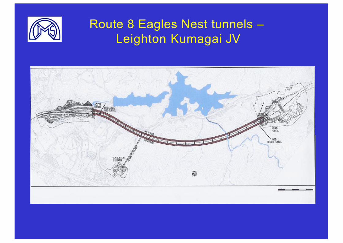
Route 8 Eagles Nest tunnels –Leighton Kumagai JV
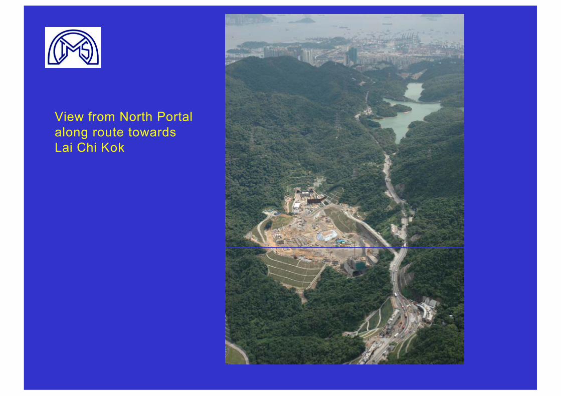
View from North Portal along route towards Lai Chi Kok
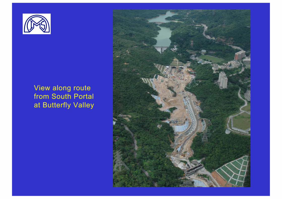
View along route from South Portal at Butterfly Valley
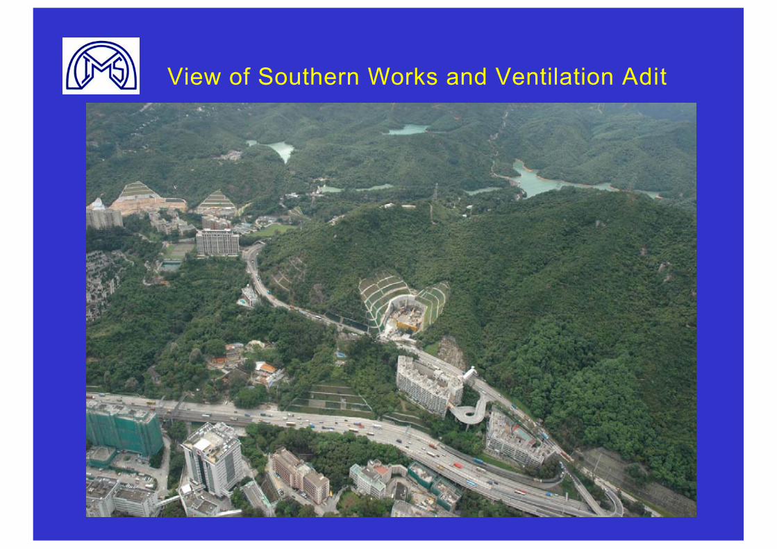
View of Southern Works and Ventilation Adit
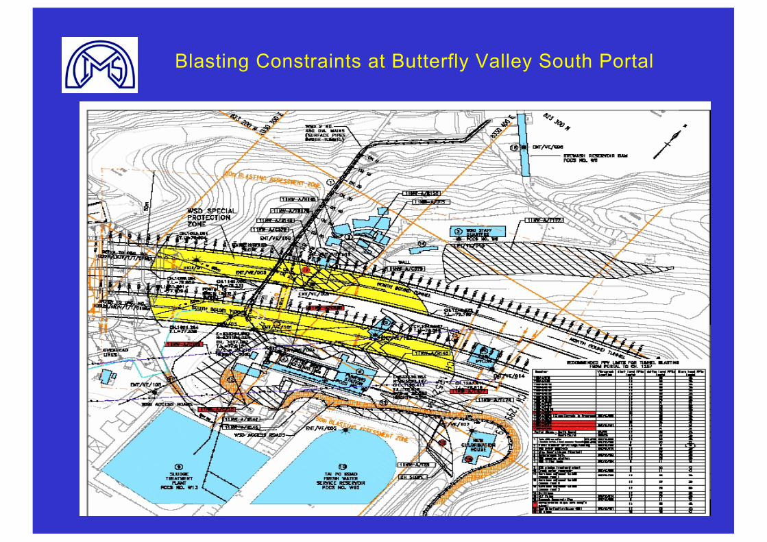
Blasting Constraints at Butterfly Valley South Portal
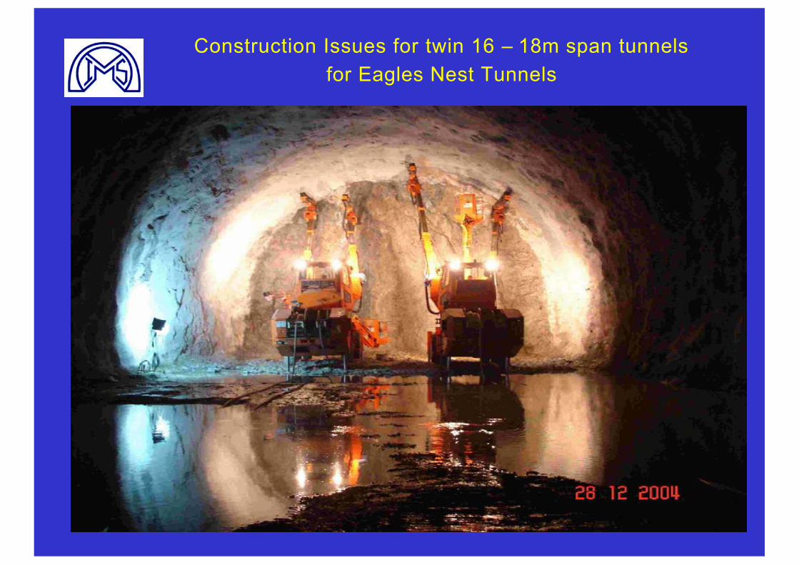
Construction Issues for twin 16 – 18m span tunnels for Eagles Nest Tunnels
Rock Classification for Selection and Design of Temporary
Support Systems
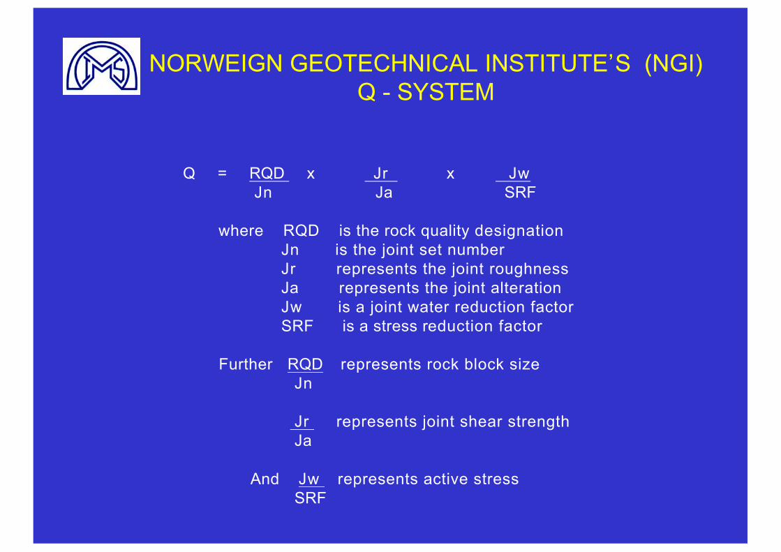
NORWEIGN GEOTECHNICAL INSTITUTE’S (NGI) Q - SYSTEM
Q = RQD x Jr x JwJn Ja SRF
where RQD is the rock quality designationJn is the joint set numberJr represents the joint roughnessJa represents the joint alterationJw is a joint water reduction factorSRF is a stress reduction factor
Further RQD represents rock block sizeJn
Jr represents joint shear strengthJa
And Jw represents active stressSRF
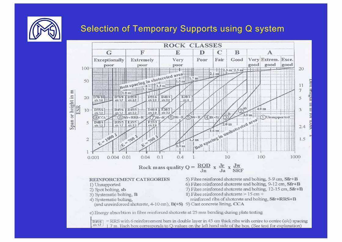
Selection of Temporary Supports using Q system

‘The problem is mathematics is black and white but the real world is grey’ – Albert Einstein
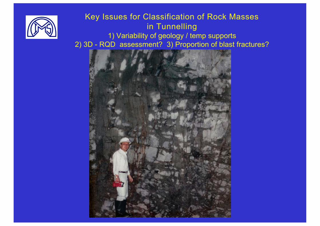
Key Issues for Classification of Rock Masses in Tunnelling
1) Variability of geology / temp supports 2) 3D - RQD assessment? 3) Proportion of blast fractures?
Are geotechnical engineers thinking for themselves -
or simply following the pack ?
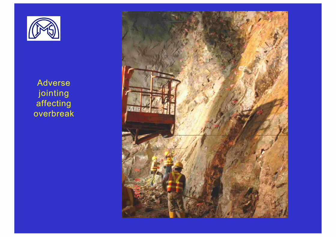
Adversejointing
affectingoverbreak
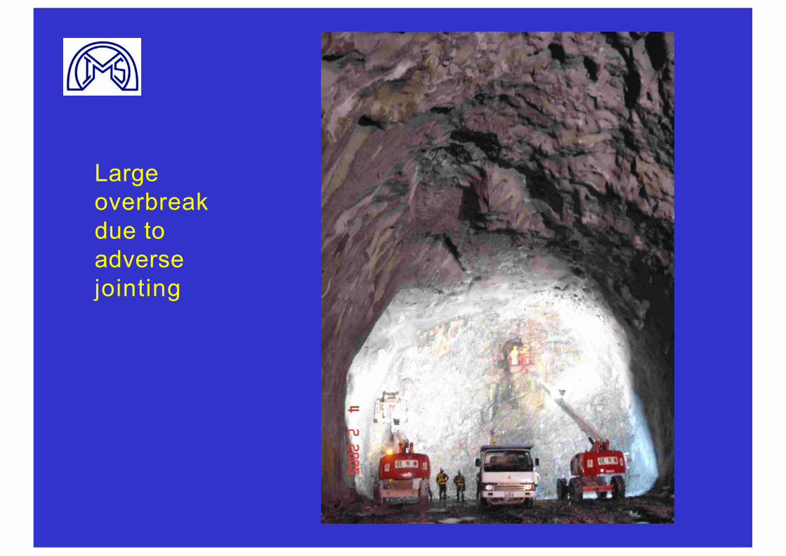
Largeoverbreakdue to adversejointing
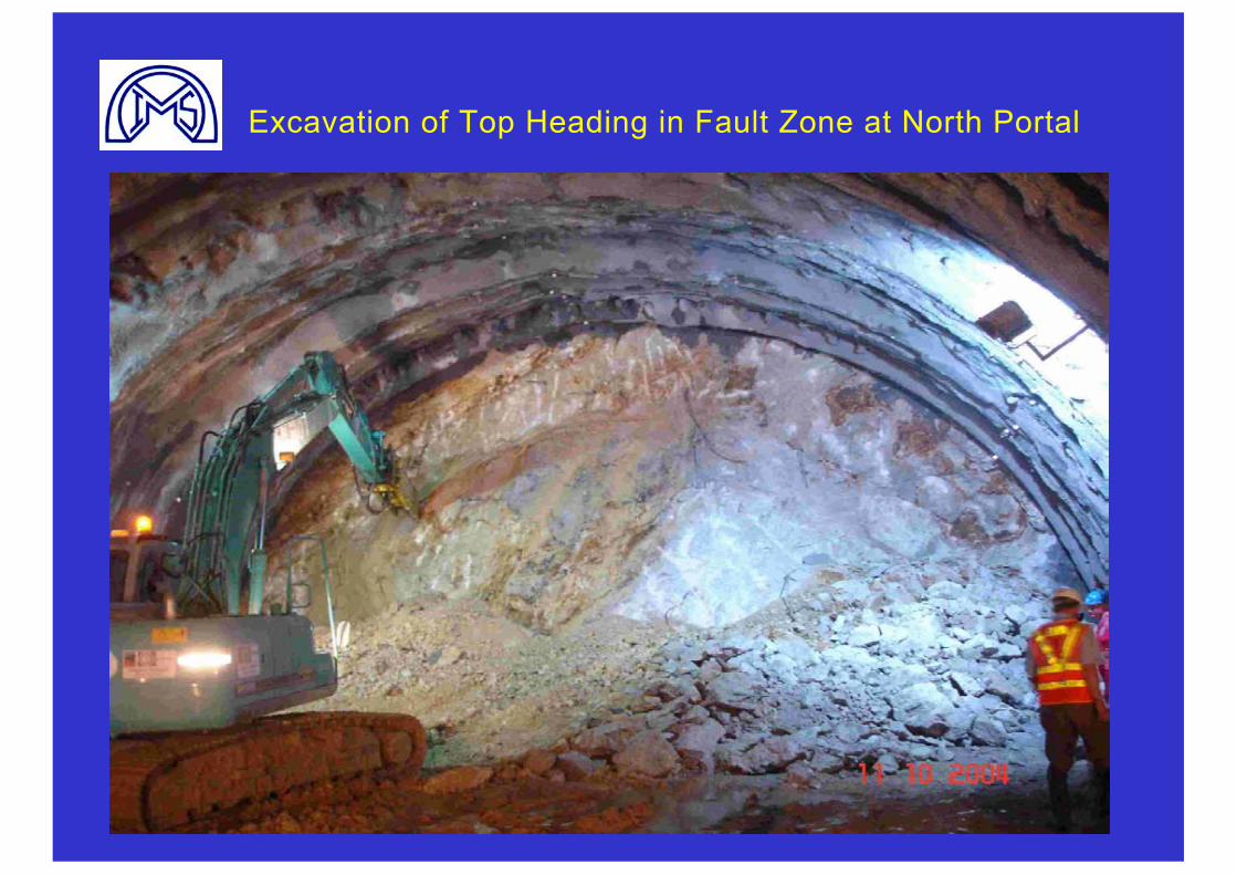
Excavation of Top Heading in Fault Zone at North Portal
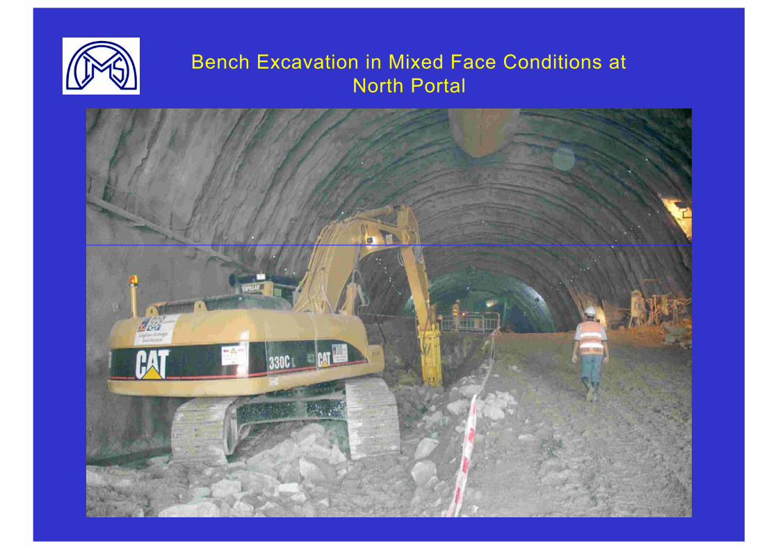
Bench Excavation in Mixed Face Conditions at North Portal
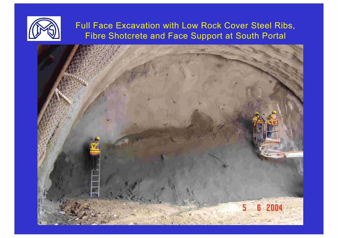
Full Face Excavation with Low Rock Cover Steel Ribs, Fibre Shotcrete and Face Support at South Portal
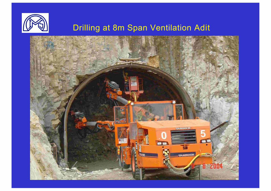
Drilling at 8m Span Ventilation Adit
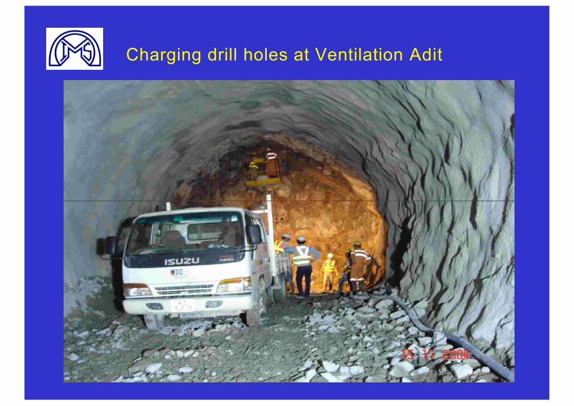
Charging drill holes at Ventilation Adit
Management and Prediction of Water Inflows in Rock Tunnelling
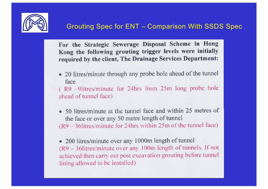
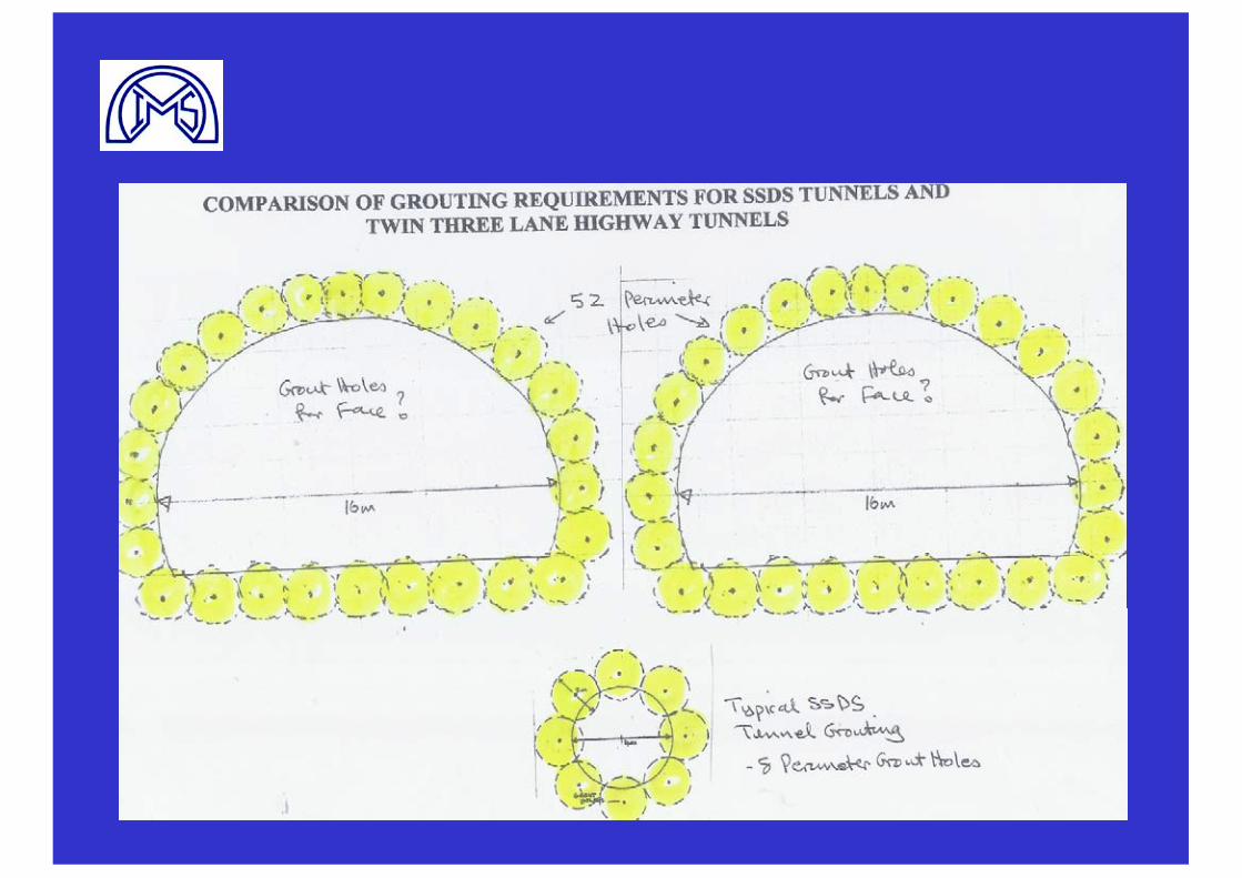
Grouting Spec for ENT – Comparison With SSDS Spec
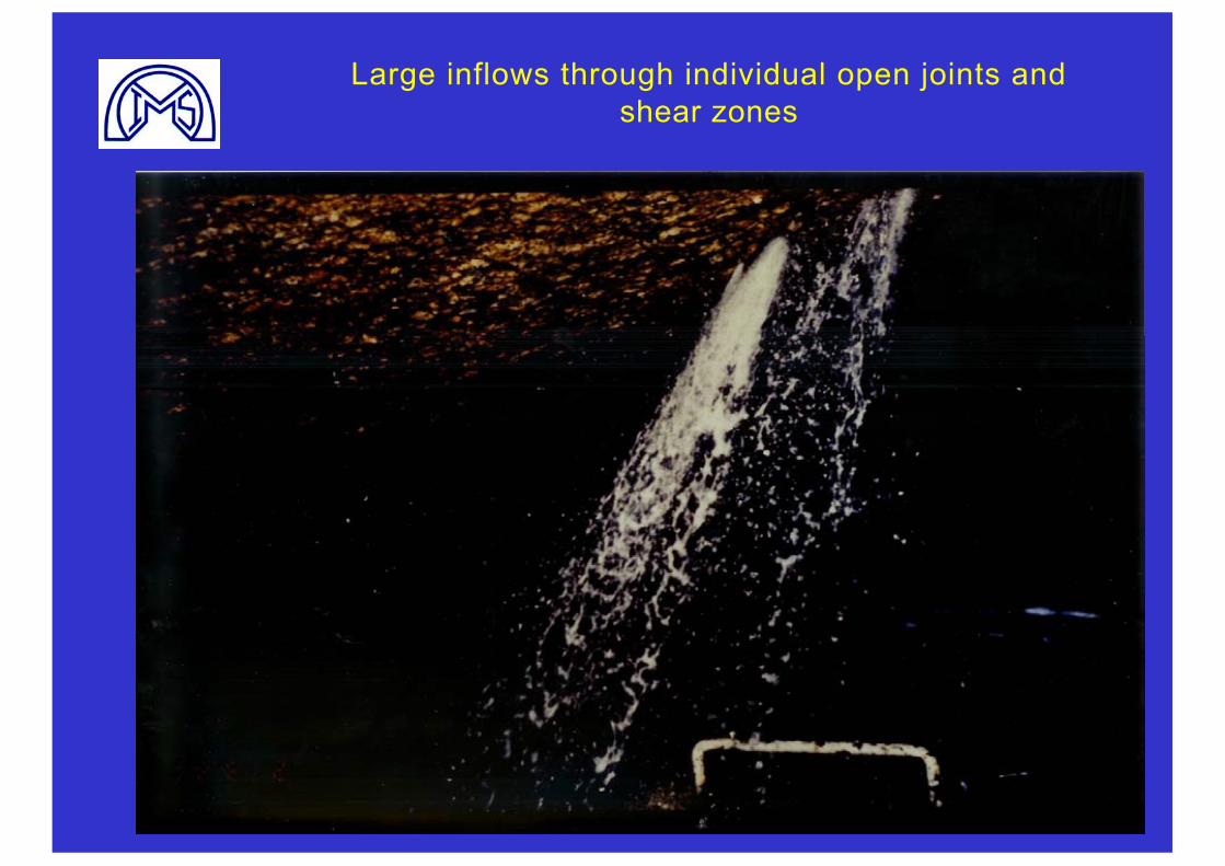
Large inflows through individual open joints and shear zones
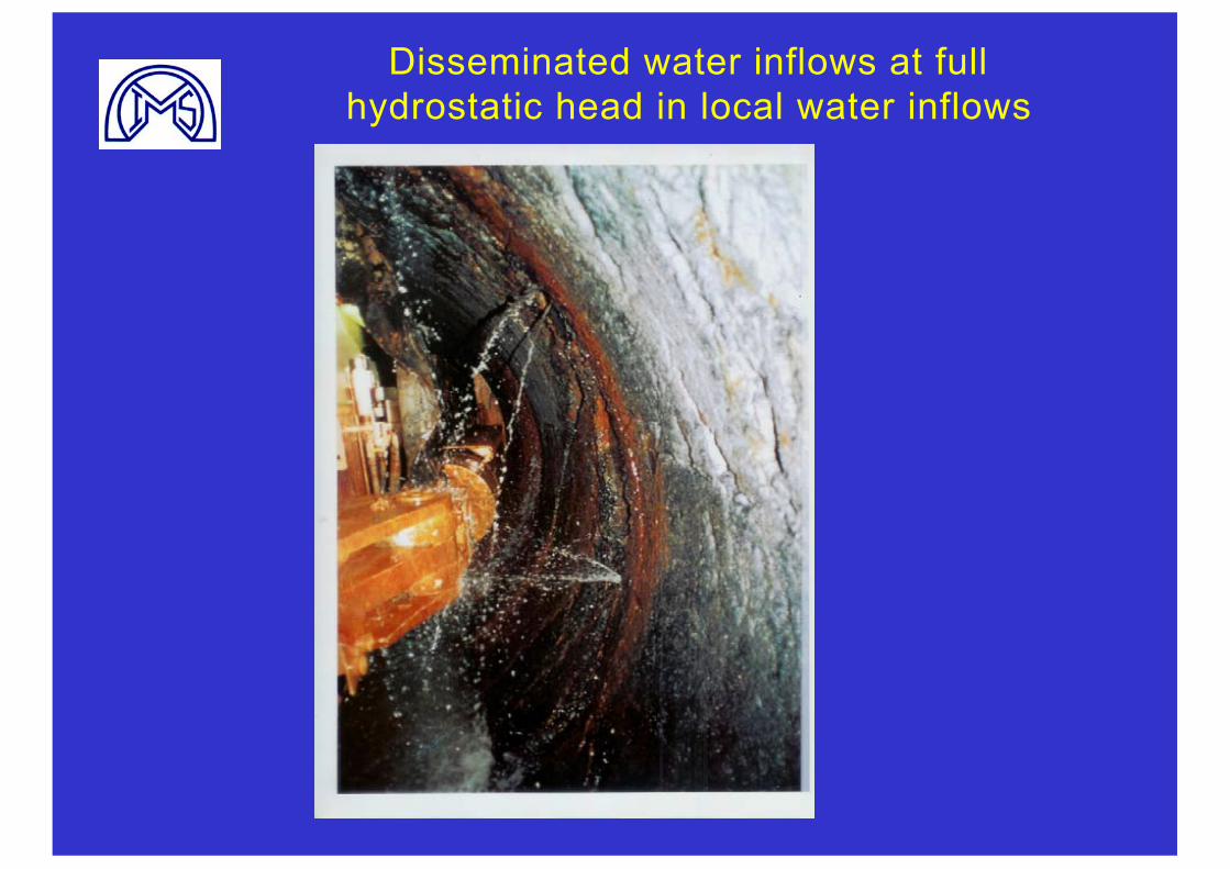
Disseminated water inflows at full hydrostatic head in local water inflows
PREDICTION OF WATER INFLOWS INTO ROCK TUNNELS IN HONG KONG
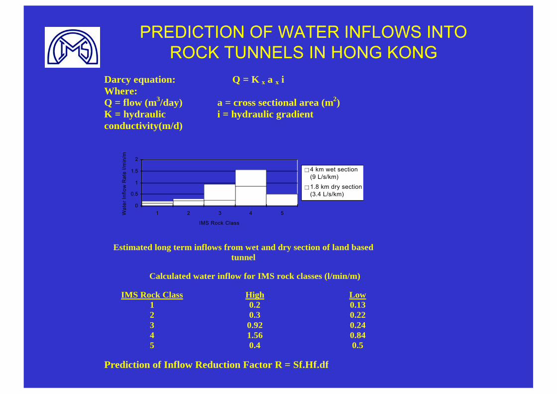
Darcy equation: Q = K x a x iWhere:Q = flow (m3/day)K = hydraulicconductivity(m/d)
a = cross sectional area (m2)i = hydraulic gradient
0
0.5
1
1.5
2
1 2 3 4 5
IMS Rock Class
Wat
er In
flow
Rat
e l/m
in/m
4 km wet section(9 L/s/km)1.8 km dry section(3.4 L/s/km)
Estimated long term inflows from wet and dry section of land based tunnel
Calculated water inflow for IMS rock classes (l/min/m)
IMS Rock Class High Low1 0.2 0.132 0.3 0.223 0.92 0.244 1.56 0.845 0.4 0.5
Prediction of Inflow Reduction Factor R = Sf.Hf.df
PREDICTION OF WATER INFLOWS INTO ROCK TUNNELS IN HONG KONG
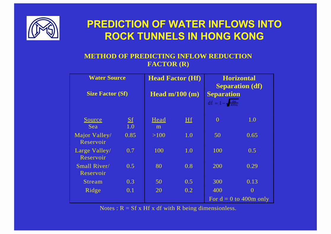
METHOD OF PREDICTING INFLOW REDUCTION FACTOR (R)
Water Source Head Factor (Hf) HorizontalSeparation (df)
Size Factor (Sf) Head m/100 (m) Separationdf dm
m1 400
SourceSea
Sf1.0
Headm
Hf 0 1.0
Major Valley/ Reservoir
0.85 >100 1.0 50 0.65
Large Valley/ Reservoir
0.7 100 1.0 100 0.5
Small River/ Reservoir
0.5 80 0.8 200 0.29
Stream 0.3 50 0.5 300 0.13
Ridge 0.1 20 0.2 400 0
For d = 0 to 400m only
Notes : R = Sf x Hf x df with R being dimensionless.
PREDICTION OF WATER INFLOWS INTO ROCK TUNNELS IN HONG KONG
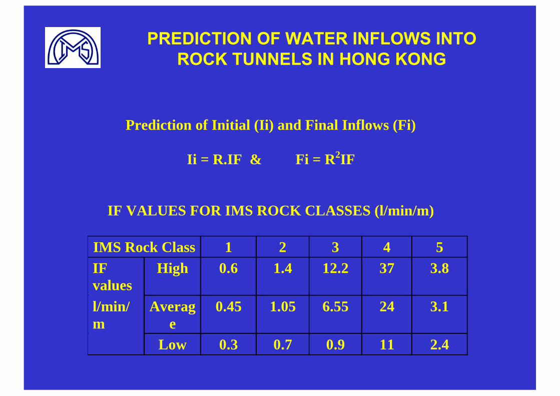
Prediction of Initial (Ii) and Final Inflows (Fi)
Ii = R.IF & Fi = R2IF
IF VALUES FOR IMS ROCK CLASSES (l/min/m)
IMS Rock Class 1 2 3 4 5IFvalues
High 0.6 1.4 12.2 37 3.8
l/min/m
Average
0.45 1.05 6.55 24 3.1
Low 0.3 0.7 0.9 11 2.4
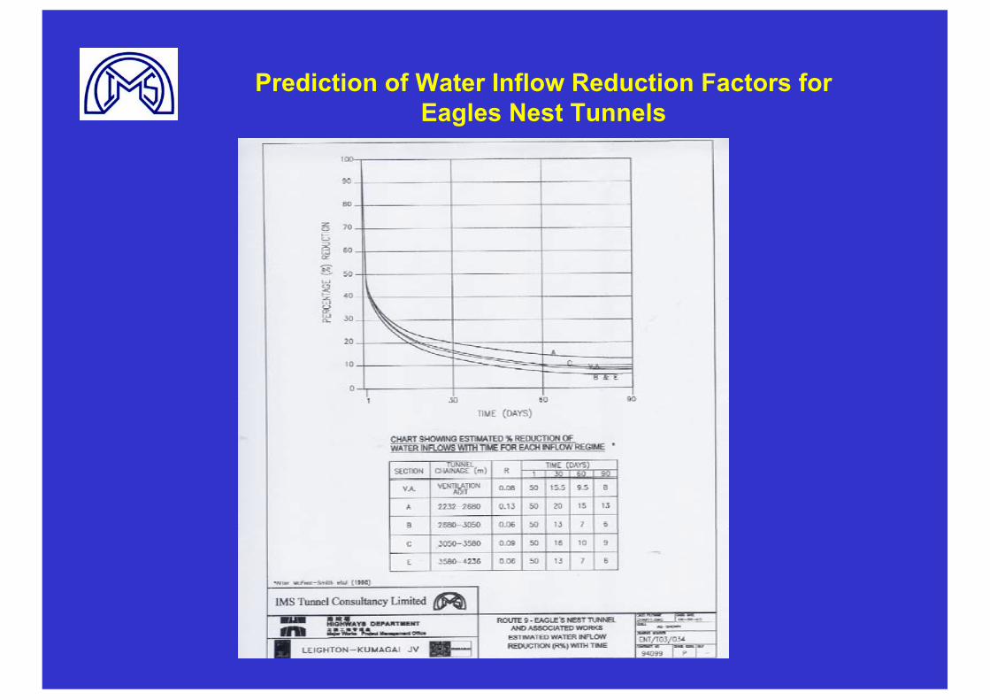
Prediction of Water Inflow Reduction Factors for Eagles Nest Tunnels
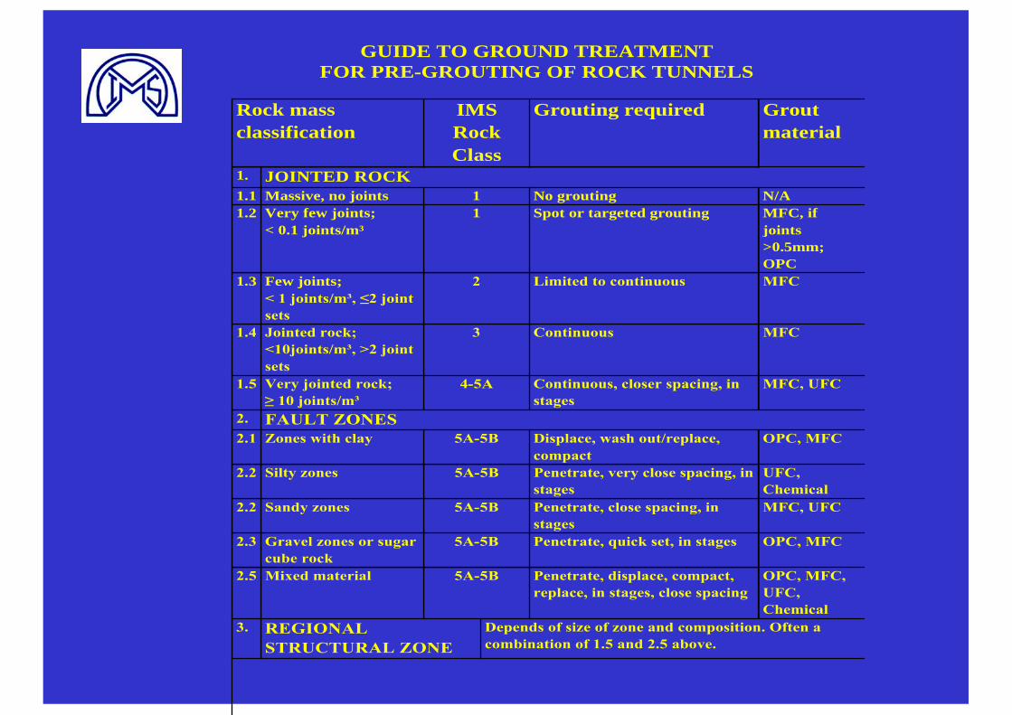
GUIDE TO GROUND TREATMENT FOR PRE-GROUTING OF ROCK TUNNELS
Rock mass classification
IMSRockClass
Grouting required Groutmaterial
1. JOINTED ROCK1.1 Massive, no joints 1 No grouting N/A1.2 Very few joints;
< 0.1 joints/m³1 Spot or targeted grouting MFC, if
joints>0.5mm;OPC
1.3 Few joints;< 1 joints/m³, ≤2 joint sets
2 Limited to continuous MFC
1.4 Jointed rock;<10joints/m³, >2 joint sets
3 Continuous MFC
1.5 Very jointed rock;≥ 10 joints/m³
4-5A Continuous, closer spacing, in stages
MFC, UFC
2. FAULT ZONES2.1 Zones with clay 5A-5B Displace, wash out/replace,
compactOPC, MFC
2.2 Silty zones 5A-5B Penetrate, very close spacing, in stages
UFC,Chemical
2.2 Sandy zones 5A-5B Penetrate, close spacing, in stages
MFC, UFC
2.3 Gravel zones or sugar cube rock
5A-5B Penetrate, quick set, in stages OPC, MFC
2.5 Mixed material 5A-5B Penetrate, displace, compact, replace, in stages, close spacing
OPC, MFC, UFC,Chemical
3. REGIONALSTRUCTURAL ZONE
Depends of size of zone and composition. Often a combination of 1.5 and 2.5 above.
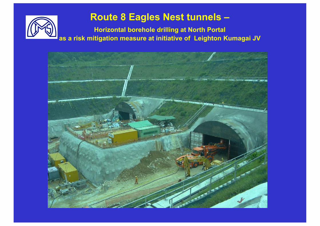
Route 8 Eagles Nest tunnels –Horizontal borehole drilling at North Portal
as a risk mitigation measure at initiative of Leighton Kumagai JV
Route 8 Eagles Nest tunnels–Contractual Issues and Risk Management
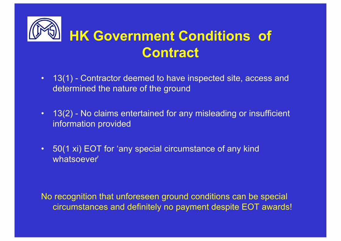
HK Government Conditions of Contract
• 13(1) - Contractor deemed to have inspected site, access and determined the nature of the ground
• 13(2) - No claims entertained for any misleading or insufficient information provided
• 50(1 xi) EOT for ‘any special circumstance of any kind whatsoever’
No recognition that unforeseen ground conditions can be special circumstances and definitely no payment despite EOT awards!
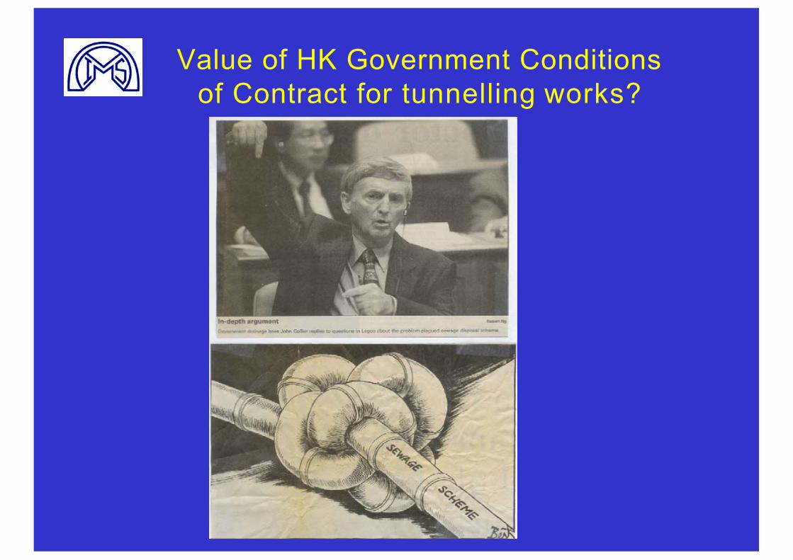
Value of HK Government Conditionsof Contract for tunnelling works?
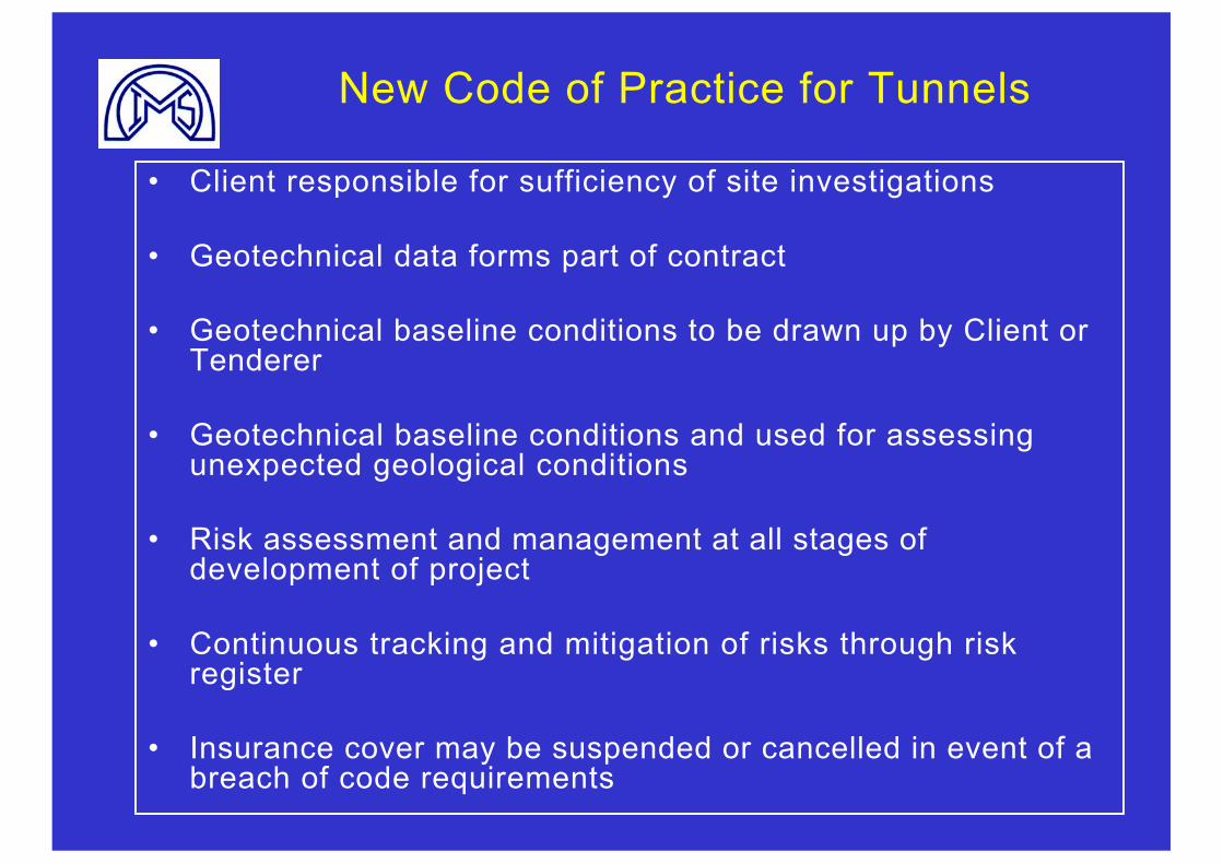
New Code of Practice for Tunnels
• Client responsible for sufficiency of site investigations
• Geotechnical data forms part of contract
• Geotechnical baseline conditions to be drawn up by Client or Tenderer
• Geotechnical baseline conditions and used for assessing unexpected geological conditions
• Risk assessment and management at all stages of development of project
• Continuous tracking and mitigation of risks through risk register
• Insurance cover may be suspended or cancelled in event of a breach of code requirements
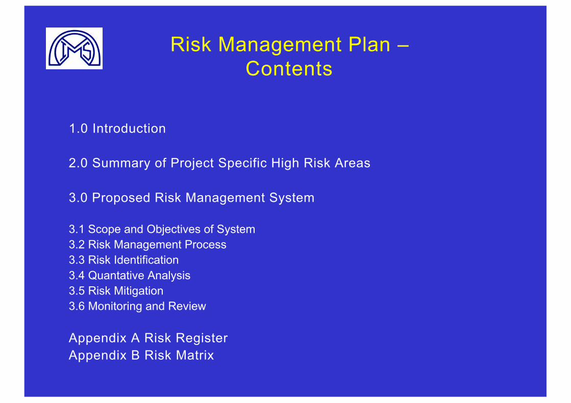
Risk Management Plan –Contents
1.0 Introduction
2.0 Summary of Project Specific High Risk Areas
3.0 Proposed Risk Management System
3.1 Scope and Objectives of System 3.2 Risk Management Process3.3 Risk Identification3.4 Quantative Analysis3.5 Risk Mitigation3.6 Monitoring and Review
Appendix A Risk RegisterAppendix B Risk Matrix
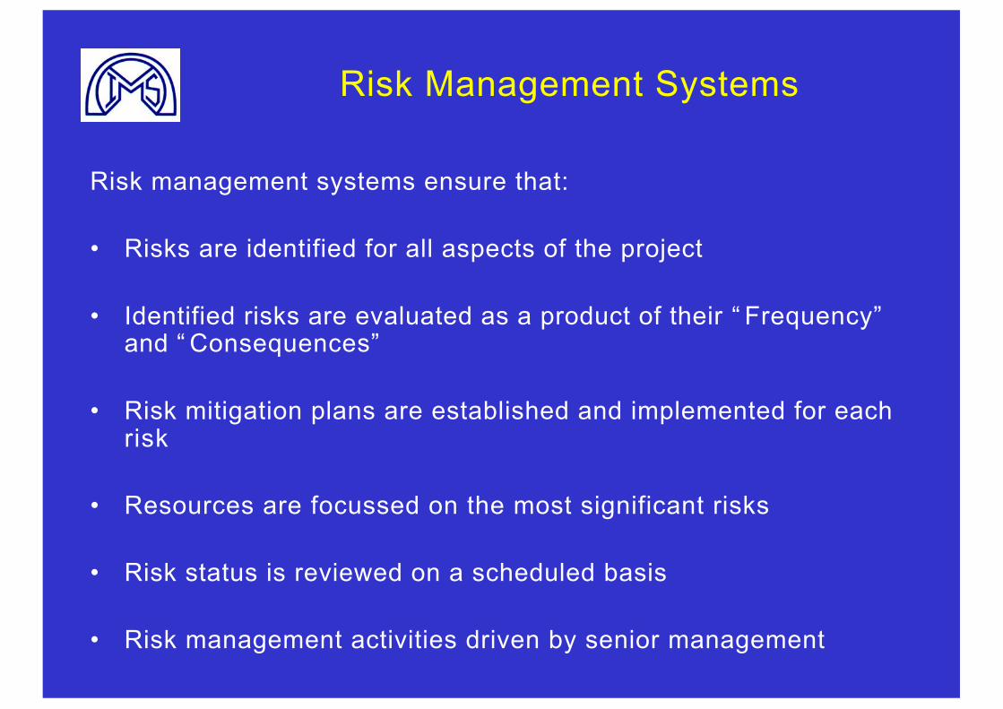
Risk Management Systems
Risk management systems ensure that:
• Risks are identified for all aspects of the project
• Identified risks are evaluated as a product of their “ Frequency”and “ Consequences”
• Risk mitigation plans are established and implemented for each risk
• Resources are focussed on the most significant risks
• Risk status is reviewed on a scheduled basis
• Risk management activities driven by senior management
Route 8 Eagles Nest tunnels–Risk Mitigation Measures
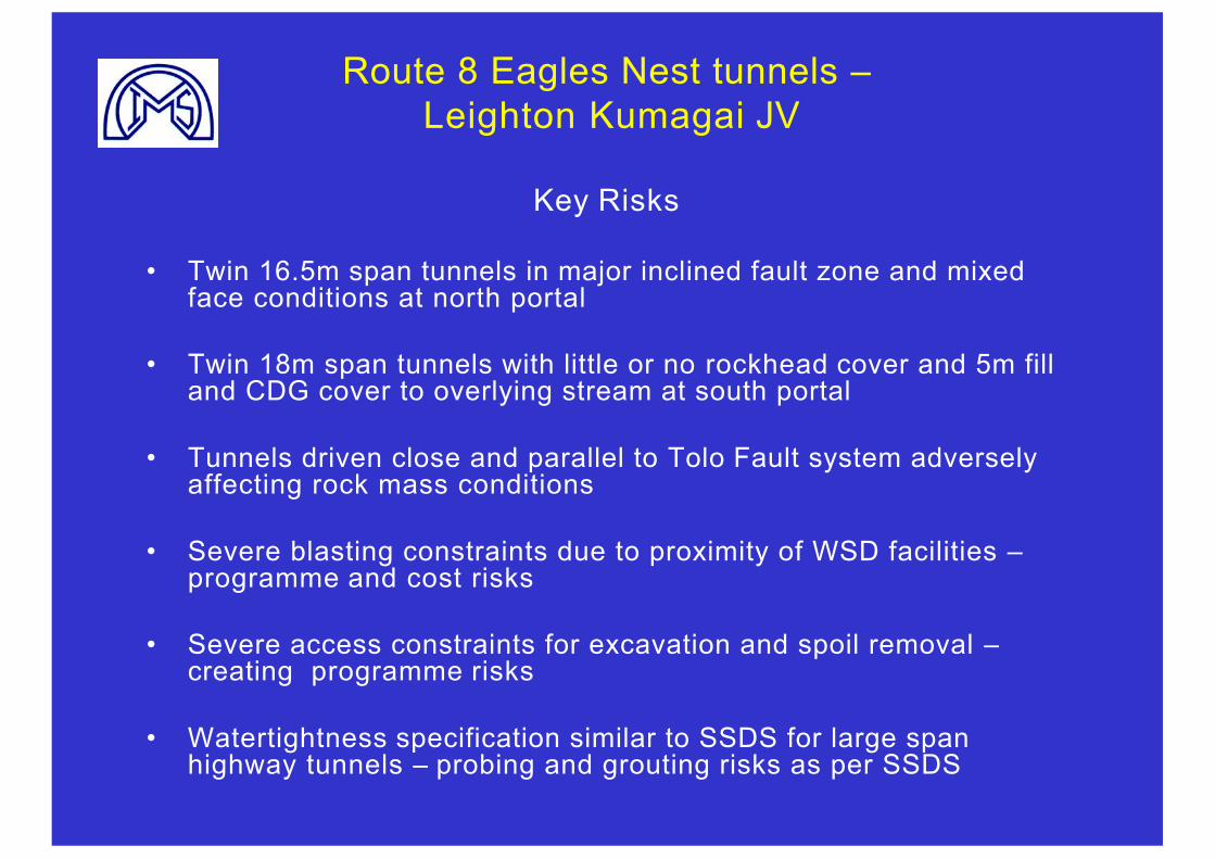
Route 8 Eagles Nest tunnels –Leighton Kumagai JV
Key Risks
• Twin 16.5m span tunnels in major inclined fault zone and mixed face conditions at north portal
• Twin 18m span tunnels with little or no rockhead cover and 5m fill and CDG cover to overlying stream at south portal
• Tunnels driven close and parallel to Tolo Fault system adversely affecting rock mass conditions
• Severe blasting constraints due to proximity of WSD facilities –programme and cost risks
• Severe access constraints for excavation and spoil removal –creating programme risks
• Watertightness specification similar to SSDS for large span highway tunnels – probing and grouting risks as per SSDS
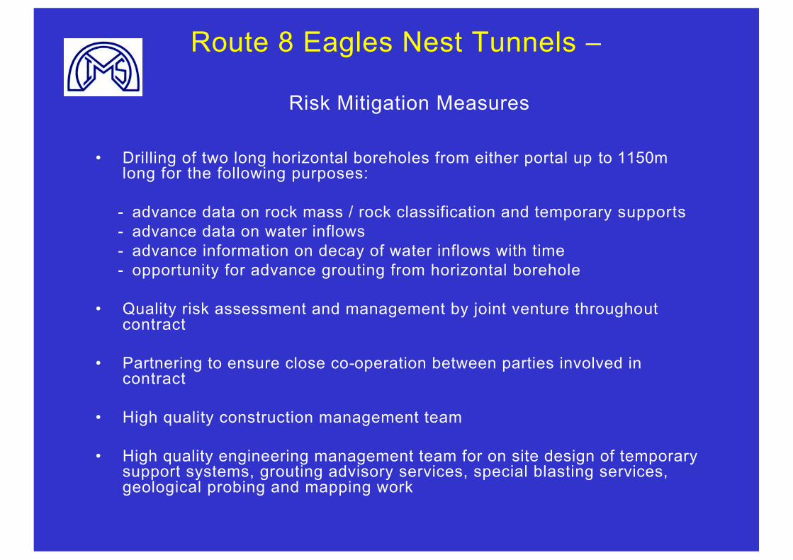
Route 8 Eagles Nest Tunnels –
• Drilling of two long horizontal boreholes from either portal up to 1150m long for the following purposes:
- advance data on rock mass / rock classification and temporary supports- advance data on water inflows- advance information on decay of water inflows with time- opportunity for advance grouting from horizontal borehole
• Quality risk assessment and management by joint venture throughoutcontract
• Partnering to ensure close co-operation between parties involved in contract
• High quality construction management team
• High quality engineering management team for on site design of temporarysupport systems, grouting advisory services, special blasting services,geological probing and mapping work
Risk Mitigation Measures
Risk Management Systems need to:-
• Ensure impartial identification and mitigation of risks particularly when such measures are expensive and time consuming
• To be developed further to provide a structured approach to the evaluation of the overall project risk on a universal basis for financing and insuring purposes.
Conclusion: Minimising Risksfor Tunnelling Projects
• Reduce uncertainty and risk by investing in well targeted site investigations
• Planning - seek specialist advice and second opinions, particularly on risks, opportunities and programmes
• Encourage technical innovation and alternative designs/approaches from contractors
• Adopt a positive attitude towards partnering – focus on openness, co-operation and fair payment
• Ensure that real engineering risk assessment and management is implemented and driven by senior management
• Consider risk sharing and re-measurement contracts