Risk Analysis Virtual Environment New Release: Version 2
12
Issue 32 December 2020 Risk Analysis Virtual Environment New Release: Version 2.0 Table of Contents • Risk Analysis Virtual Environment New Release: Version 2.0 . . . . . . . . . . . . . . . . . . . . . . . . . . . . . . . . . . . . 1 • Risk-Informed Access/Delay Timeline Development. . . . . . . . . . . . . . . . . . . . . . . . . . . . . . . . . . . . . . . . . 3 • Integrated Risk Assessment for Digital Instrumentation and Control Systems . . . . . . . . . . . . . . . . . . . . . . . . 4 • Interdigital Capacitance Sensor for Cable Insulation Test and Monitoring: A Nondestructive Method to Assess Aging and Degradation . . . . . . . . . . . . . . . . . . . . . . . . . . . . . . . . . . . . . . . . . . . . . . . . . . . . 6 • Lessons Learned for Modernizing Nuclear Power Plants from the Development of the Zumwalt Class Destroyer . . . . 8 • Hydrogen Production Safety at Nuclear Power Plants . . . . . . . . . . . . . . . . . . . . . . . . . . . . . . . . . . . . . . . . 10 • Recent LWRS Program Reports . . . . . . . . . . . . . . . . . . . . . . . . . . . . . . . . . . . . . . . . . . . . . . . . . . . . . . 12 T he Risk Analysis and Virtual ENviroment (RAVEN) team recently released version 2.0 of the RAVEN software. This software is important to sustaining the existing fleet because it is designed to analyze safety, risk, uncertainty, maintenance, testing, and asset costs Continued on next page of current reactors to support proactive management approaches. This important update in the RAVEN software series represents an important step in its development, Andrea Alfonsi, Cristian Rabiti, Diego Mandelli, Paul W. Talbot, Congjian Wang, Joshua J. Cogliati, Mohammad G. Abdo, Curtis L. Smith, Shannon M. Bragg-Sitton Risk-Informed Systems Analysis Pathway
Transcript of Risk Analysis Virtual Environment New Release: Version 2
I s s u e 3 2D e c e m b e r 2 0 2 0
Risk Analysis Virtual Environment New Release: Version 2.0
Table of Contents• Risk Analysis Virtual Environment New Release: Version 2.0 . . . . . . . . . . . . . . . . . . . . . . . . . . . . . . . . . . . . 1• Risk-Informed Access/Delay Timeline Development . . . . . . . . . . . . . . . . . . . . . . . . . . . . . . . . . . . . . . . . . 3• Integrated Risk Assessment for Digital Instrumentation and Control Systems . . . . . . . . . . . . . . . . . . . . . . . . 4• Interdigital Capacitance Sensor for Cable Insulation Test and Monitoring: A Nondestructive Method
to Assess Aging and Degradation . . . . . . . . . . . . . . . . . . . . . . . . . . . . . . . . . . . . . . . . . . . . . . . . . . . . 6• Lessons Learned for Modernizing Nuclear Power Plants from the Development of the Zumwalt Class Destroyer . . . . 8• Hydrogen Production Safety at Nuclear Power Plants . . . . . . . . . . . . . . . . . . . . . . . . . . . . . . . . . . . . . . . .10• Recent LWRS Program Reports . . . . . . . . . . . . . . . . . . . . . . . . . . . . . . . . . . . . . . . . . . . . . . . . . . . . . .12
The Risk Analysis and Virtual ENviroment (RAVEN) team recently released version 2.0 of the RAVEN software. This software is important to sustaining
the existing fleet because it is designed to analyze safety, risk, uncertainty, maintenance, testing, and asset costs Continued on next page
of current reactors to support proactive management approaches. This important update in the RAVEN software series represents an important step in its development,
Andrea Alfonsi, Cristian Rabiti, Diego Mandelli, Paul W. Talbot, Congjian Wang, Joshua J. Cogliati, Mohammad G. Abdo, Curtis L. Smith, Shannon M. Bragg-Sitton
Risk-Informed Systems Analysis Pathway

2 L W R S N E W S L E T T E R L W R S N E W S L E T T E R 3
Figure 1. RAVEN capabilities.
deployment, and consolidation of advanced capabilities for the probabilistic risk assessment (PRA), uncertainty quantification (UQ), data analysis, and machine learning (ML) communities, as observed in Figure 1.
The development of the RAVEN software has been supported by the Nuclear Energy Advanced Modeling and Simulation (NEAMS), the Light Water Reactor Sustainability (LWRS), and the Nuclear Energy Enabling Technologies Crosscutting Technology Development Integrated Energy System programs.
RAVEN provides a full and comprehensive set of capabilities to build analysis workflows based on state-of-the-art and advanced UQ, PRA, optimization, and ML techniques. The primary objectives of the software is to assist users to: (1) improve the performance of their physical design; (2) estimate the likelihood of undesired outcomes (risk analysis); (3) identify main parameters and events affecting the behavior of the model and their impact; and (4) construct analysis flows combining multiple physical models and analysis procedures.
RAVEN Version 2.0RAVEN 2.0 features improved capabilities, specifically performance enhancements, and new user applications via new RAVEN plugins. The main additions and features include:
• Performance and Parallelization – Deployed a new system for optimizing the use of complex code. This new system starts up almost instantaneously.
• Parallelization – Replaced the “Parallel Python” system with the modern and powerful RAY library (https://docs.ray.io). RAY enables high performance computing massive parallelism reducing the parallel overhead resulting in improved scalability.
• Optimization – Developed a new optimization system with support for customizable interfaces, that enables: (1) a flexible code interface for ease in developing optimization algorithms (both internally and externally); and (2) support for probability distributions (e.g., risk-weighted and robust optimization). The new system allows for a much easier and quicker development of complex optimization approaches for designing and modifying complex systems.
• Surrogate Models – Deployed an interface with the Google supported library TensorFlow (https://www.tensorflow.org/). In addition, several improvements of the RAVEN synthetic time series generator have been developed (e.g., the generation of correlated multi signals with unbiased sampling for the synthetic time series generation).
• Post Processing and Data Analysis – RAVEN 2.0 has the following new post-processing capabilities:– Risk Assessment: Developed a new post-processor aimed
to import/load/use minimal cut-sets generated by an external PRA code (e.g., SAPHIRE).
Continued from previous page – Reliability Analysis: Added the option to compute the bounding error of the limit surface (maximum error on the computed probability of failure).
– Economic Analysis: Developed a “Pareto Frontier” algorithm for the identification of the points lying on a boundary in a cost-value space.
Plugins and Code CouplingThe RAVEN software has always been characterized by high “reusability” of the available algorithms and methods for deploying different use cases. RAVEN allows for the creation of plugins—software components that can be either imported by RAVEN as an additional toolbox or can use RAVEN as a calculation engine. In RAVEN 2.0, three new plugins have been released:
• LOGOS: Provides computational capabilities to optimize plant resources such as maintenance optimization and optimal component replacement schedule by using state-of-the-art discrete optimization methods.
• SR2ML: Provides sets of components and maintenance reliability models for quantification. These models can be used to determine an optimal system maintenance posture.
• SRAW: Provides sets of advanced workflows and methods to be applied to plant health and asset management. These methods focus on maintenance and replacement optimization and system reliability/unavailability.
In addition to the significant code enhancements, the documentation and training material has also been updated. The open source RAVEN 2.0 can be downloaded from: https://github.com/idaholab/raven/releases/tag/RAVENv2.0. https://raven.inl.gov: Version 2.0.
Data MiningOptimization
SensitivityAnalysis
ModelCalibration
UncertaintyQuanti�cation
ProbabilisticRisk Analysis

2 L W R S N E W S L E T T E R L W R S N E W S L E T T E R 3
Physical security systems rely on three main elements for protection: detection, delay, and
response. Performance and reliability of these systems are tested, but due to the costs with constructing and testing delay barriers, security experts are often forced to work with small datasets that are not well suited to traditional frequentist statistical methods. To provide better insight into overall system performance, the LWRS Program is investigating methods through SNL that leverage Bayesian methods to better integrate subject matter expert (SME) analysis with these small test datasets. This will provide a more holistic view of delay performance, including state-of-knowledge uncertainty.
Historically, delay timelines consist of a set of individual tasks with their associated times—informed by data when feasible and informed by SME judgement when not. Tasks are defined by a single-time data point for the task to be completed. In practice, these tasks have a range of times that can be described by a probability distribution. By shifting from a single-time data point for each task and moving to a probability distribution, Monte Carlo sampling from each task distribution can be used to estimate: (1) the distribution of task times in which the full timeline could plausibly be completed; and (2) the probability that a timeline could be completed given that unrecoverable failures may occur.
This new approach shifts the focus from finding ways to address the shortest potential adversary timeline to a broader view of security that allows the user to gain a deeper understanding of where modifications to the physical security system will have the most impact on reducing overall security risk. Specifically, timelines for a variety of pathways can be developed using these methods. Sensitivity analysis can be used to identify areas where additional delay barriers will provide the greatest effect on overall system performance.
When developing the timelines, Bayesian statistics can be used to formalize how SME judgement can be supplemented by small datasets in a way that is explainable and defensible.
An early demonstration of the output of this capability can be seen in Figure 2. For this example, SNL demonstrated the method by utilizing three sets of SMEs to generate timelines. Additionally, one of the SME groups collected
performance test data for select tasks within the timeline. By compiling this data using Bayesian methods, the team produced probability distributions for the time duration of the full path, as well as the likelihood of success.
These probability distributions can also be used in conjunction with other tools for evaluating system performance, such as DANTE [1], AVERT [2], or Simajin/VANGUARD [3]. This new risk-informed approach provides more realistic quantification of scenarios than previous methods and results in higher fidelity simulations of the full physical security system, including detection and response. As this method develops, the team hopes to implement tools to aid security experts in developing timelines that can be used to support risk-informed decision making and improve the overall security at nuclear facilities.
References1. Sandia National Laboratories developed physical security
modeling software, https://www.osti.gov/servlets/purl/1431716.
2. ARES Security Corp. developed physical security modeling software, https://aressecuritycorp.com/avert.
3. Rhino Corps. developed physical security modeling software, https://www.rhinocorps.com/products/.
Risk-Informed Access/Delay Timeline Development
Figure 2. Example distributions for (left) timeline duration probability and (right) probability of adversary success.
Dusty M. Brooks and Andrew D. Thompson Physical Security Pathway
0 0
0.2
0.4
0.6
0.8
1.0
0.1
0.2
0.3
0.4
0.5
0.6
Exce
edan
ce Pr
obab
ility
Time (min) Probability of Adversary Success
Cum
ulat
ive Pr
obab
ility0.7
0.8
0.9
1.0
SME 1SME 2SME 3MeanMean fromBayesianAnalysis
SME 1SME 2SME 3Mean

4 L W R S N E W S L E T T E R L W R S N E W S L E T T E R 5
Risk-Informed Systems Analysis Pathway researchers, along with industry collaborators, are developing an integrated risk assessment approach to evaluate
digital instrumentation and control (I&C) systems. This approach considers common cause failures (CCFs) and plant transient responses to provide the technical basis supporting effective, licensable, and secure digital I&C technologies for upgrades to existing nuclear power plants. This technical basis is instructive for nuclear vendors and utilities to effectively lower the costs associated with digital compliance and speed-up industry advances by: (1) defining an integrated risk-informed analysis approach for digital I&C upgrades including hazard analysis, reliability analysis, and consequence analysis; (2) applying systematic and risk-informed tools to address CCFs and quantify failure probabilities for digital I&C technologies; (3) evaluating the impact of digital failures at the component-level,
system-level, and plant-level; and (4) providing insights and suggestions on designs to manage the risks to support the development, licensing, and deployment of digital I&C technologies to nuclear power plants.
Risk Assessment for Digital I&C Systems – An Integrated ApproachDigital I&C upgrades must be cost-effective and meet current licensing and qualification requirements for these systems. An integrated multi-disciplinary approach, defined as Risk Assessment for Digital I&C (RADIC), as displayed in Figure 3, supports this strategy. RADIC has three key parts—hazard analysis, reliability analysis, and consequence analysis.
Hazard analysis focuses on identifying both software and hardware failures and building models (i.e., fault trees).
Integrated Risk Assessment for Digital Instrumentation and Control Systems
Figure 3. Schematic of the Risk Assessment for Digital I&C (RADIC).
Han Bao, Hongbin Zhang, and Curtis Smith Risk-Informed Systems Analysis Pathway
Digital I&C Systems
Suggestions to reduce risks(e.g., eliminating root faults and triggers of CCFs,
increasing reliability of important components
Acceptance CriteriaAre the digital failures acceptable at individual
level, system level or lant level?
Consequence Analysis Risk AnalysisHazard Analysis Reliability Analysis
Application
Risk Assessment
Redesign
Yes
No
• Identify hazards• Estimate probabilities• Analyze consequences
Risk Evaluation
• Compare risk analysis results with speci�c risk acceptance criteria

4 L W R S N E W S L E T T E R L W R S N E W S L E T T E R 5
The acceptance criterion for hazard analysis is whether the individual digital failure leads to the loss of system function. In previous PRAs for analog systems, hardware failures were the focus. In this research, Nancy Leaveson, a researcher at Massachusetts Institute of Technology, used a Systems-Theoretic Process Analysis method, to identify potential software failures. The integration of software failures into the existing hardware fault tree in RADIC is further developed using the Hazard and Consequence Analysis for Digital Systems (HAZCADS) method jointly developed by the Electric Power Research Institute (EPRI) and Sandia National Laboratories (SNL). The reliability analysis quantifies the integrated fault trees and building event trees to represent the consequences of digital system failures.
A Case Study on a Representative Digital Safety SystemCurrently, the RADIC approach is being demonstrated on representative digital safety systems including the reactor trip system and Engineered Safety Features Actuation Systems (ESFASs). The key outcomes are an integrated fault
tree that includes both hardware and software failures and ways to identify potential hazards that may make the digital system fail. To characterize this, a detailed hardware representation of the digital ESFAS was developed as shown in Figure 4. Next, a fault tree of hardware failures was developed for system failure, followed by using a modified systematic hazard analysis approach that includes software failures.
Researchers are using these models to characterize the strengths and weakness of the digital I&C system and provide recommendations to system designers and plant operators/owners to efficiently reduce system vulnerabilities. By integrating hazard analysis, reliability analysis, and consequence analysis together, this risk assessment strategy aims to: (1) help system designers and engineers to systematically address digital-based CCFs and quantitatively analyze their effects on digital-system vulnerability and key plant responses; (2) improve existing PRA models for the industry by identifying and evaluating the risk associated with digital I&C technologies; and (3) provide risk insights to address the licensing challenges facing digital I&C upgrades.
Figure 4. Detailed hardware representation of the digital ESFAS.

6 L W R S N E W S L E T T E R L W R S N E W S L E T T E R 7
Degradation of installed electrical cable within nuclear power plants is
known to occur as a function of age and operating environment. With more than 1,000 km of power, control, and instrumentation cables typically found in a plant, complete replacement could be a severe cost burden. Methods are therefore needed to nondestructively assess aging and degradation of cable materials to assess their performance.
There are a number of nondestructive approaches to assess cable insulation [1]. Bulk and distributed tests, applied from the cable ends, provide an overall cable condition assessment (e.g., withstand resistance, Tan-Delta, dielectric spectroscopy). Distributed tests (e.g., partial discharge, time-domain, frequency-domain, and joint time-frequency domain reflectometry) also identify potential damage location information for follow-up by local tests. Local tests include visual inspection, thermographic infrared inspection, Fourier-transform infrared spectroscopy, near infrared, indenter modulus, and interdigital capacitance (IDC) [2]. IDC is the only local test that directly evaluates electrical characteristics of insulation, arguably the most relevant feature, and is applicable to cables without shield, foil, or semiconductor isolation between the IDC sensor and the insulation to be tested. This constraint still leaves a large population of cables that can be tested.
Frequently, the external jacket of a cable is significantly
degraded while the underlying insulation is good. LWRS Program researchers at Pacific Northwest National Laboratory (PNNL) have extended the IDC test to evaluate insulation through an intact jacket, significantly extending the number of cables that can be assessed. By exploiting depths of field of the measurement with wide and narrow sensor tine spacing, insulation condition can be inferred through a jacket. This is the only known test that can assess the
insulation condition through a polymer jacket and adds to the appeal of an IDC measurement approach.
Motivated by the need to inspect wire insulation in aircraft, spacecraft, and nuclear power plants, single-sided access capacitive sensors whose two electrodes conform to the cylindrical surface of the insulated wire have been developed [3] to infer permittivity of the wire insulation from measured sensor capacitance. The cable IDC test consists of two electrodes, with fork-like tines interspersed and separated by a small gap, printed on one side of a flexible substrate that can be conformed to the surface of a cylindrical cable, as observed in Figure 5.
The penetration depth of the dynamic electromagnetic field—commonly known as the skin depth—is defined as the depth at which the field magnitude falls to approximately 37% of its surface value. In a low-loss (dielectric) material like cable insulation, the depth of field
S.W. (Bill) Glass and Leo S. Fifield Materials Research Pathway
Interdigital Capacitance Sensor for Cable Insulation Test and Monitoring: A Nondestructive Method to Assess Aging and Degradation
Figure 5. (a) Unjacketed cable cross section with IDC; (b) jacketed cross section, and (c) orthogonal view of IDC.
Substrate g
w
δ
Interdigital Electrode
IDC SensorTines
Insulation(a) (b) (c)
CentralConductor
Jacket

6 L W R S N E W S L E T T E R L W R S N E W S L E T T E R 7
was found to be approximately linearly equal to the tine gap. This is important for the dual tine IDC sensor to assess the insulation condition beneath a polymer jacket, as observed in Figure 6.
A set of ethylene-propylene rubber insulated cables with a chlorinated polyethylene jacket were thermally aged at 140°C to produce a range of age-related permittivity values for IDC capacitance and dissipation factor measurements, as observed in Figure 7. The cables were aged and measured using both a wide and narrow tine IDC used to infer the condition of the insulation through the jacket. Jackets were removed on half of each sample and inferred condition of the insulation verified through direct measurement. Measurement versus prediction is plotted
in Figure 8, with an observed correlation R2 value of 0.98 (where a perfect R2 correlation = 1.0).
ConclusionsVarious forms of IDC sensors can either be used to manually test local cable conditions or as permanently installed sensors to measure cable jacket and insulation conditions. PNNL advancement has expanded applicability of IDC insulation measurement to include unshielded jacketed cables.
Dual gap IDC sensors are confirmed to be able to sense the insulation condition beneath a polymer jacket and, moreover, the IDC is the only known way to assess the insulation condition through the jacket. PNNL has filed a patent for this approach and is exploring commercial partnerships to exploit IDC technology for actionable field measurements.
References1. Glass, SW; LS Fifield; G Dib; JR Tedeschi; AM Jones; and
TS Hartman. 2015. State of the Art Assessment of NDE Techniques for Aging Cable Management in Nuclear Power Plants FY2015. Pacific Northwest National Laboratory, Richland, WA, USA.
2. Glass, SW; LS Fifield; TS Hartman. 2016. Evaluation of Localized Cable Test Methods for Nuclear Power Plant Cable Aging Management Programs. Pacific Northwest National Laboratory, Richland, WA, USA.
3. Chen, T; N Bowler, 2012. “Analysis of a capacitive sensor for the evaluation of circular cylinders with a conductive core.” Measurement Science and Technology 23 (4):045102. doi: 10.1088/0957 0233/23/4/045102.
Figure 6. Finite element simulation of field penetration depth (red) as a function of tine (yellow) gap (upper right – tight;
lower left-medium, lower right-wide tine gap.
Figure 7. Pink EPR insulation; chlorinated polyethylene jacket aged samples with jacket removed from half of the sample.
Figure 8. Measured vs. predicted dissipation factor of insulation based on measurements through jacket.
Unaged
Jacket-Outside
Jacket-Inside
Jacket
Insulation
7d
12d
14d
21d
28d
35d
Pred
icted
from
/thro
ugh j
acke
t
Measured on Insulation
R2 = 0.98
00
0.05
0.1
0.15
0.2
0.05 0.1 0.15 0.2
100 KHz Dissipation Factor
8 L W R S N E W S L E T T E R L W R S N E W S L E T T E R 9
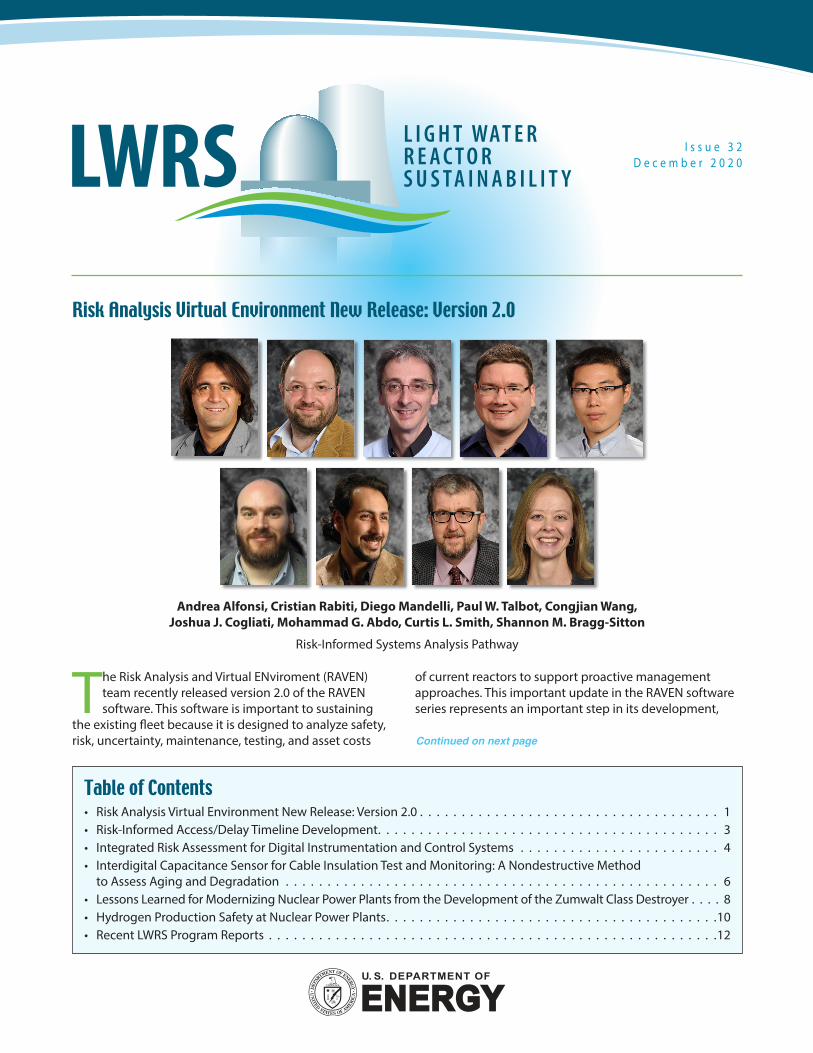
LWRS Program researchers have been collaborating with research colleagues from the U.S. Navy to use macro-ergonomics to help the U.S. nuclear industry
proactively address future operational uncertainties. Continuous improvement of nuclear energy operations depends on the effective introduction of modern technologies—automation, advanced human-system interface concepts, remote sensing technologies, drones—and new approaches to management and operations that can effectively leverage these capabilities. Concepts and practices such as the virtual organization and integrated operations are needed, and macro-ergonomic concepts are essential to the strategic decision-making processes needed for successful plant modernization and organizational restructuring.
For virtually all commercial nuclear power plants, operations and maintenance (O&M) costs are significant contributors to the costs of plant ownership. The U.S. Navy found itself in a very similar situation in the late 1990s, experiencing similar O&M concerns, which if not addressed could affect future operational readiness.
The Navy pursued a radically new vision to replace traditionally crew-heavy platforms, a process that eventually led to the design and deployment of the USS Zumwalt class of destroyers—the Zumwalt, (seen in Figure 9), is the Navy’s first ‘optimally manned’ surface combatant of its size. The Zumwalt was also the first of its kind to rely heavily on the performance of automated systems and significantly transformed organizational concepts.
Recently, LWRS Program researchers at Idaho National Laboratory (INL) organized and participated in four virtual conferences with U.S. Navy researchers, designers, and training personnel who were directly involved in the Zumwalt design process. The goal of these discussions was to explore lessons-learned from the latter that could
benefit approaches to similar efforts within the nuclear energy industry.
The Zumwalt was a highly complex systems engineering effort, many of whose features resemble those encountered by the nuclear industry:
• Safety-critical system – U.S. Navy warships are inherently safety-critical both in terms of the risk of the overall mission and in the potential risks to the personal safety and well-being of sailors and others. Improving system safety and reliability are also generally viewed as key strategic warfighting advantages and objectives.
• High reliance on automation and remote sensing – The significant reduction in crew size from legacy destroyers to the Zumwalt (from approximately 350 to the Zumwalt’s current crew size of approximately 140) without sacrifice of safety or operational capability meant that enormous amounts of ‘human workload’ had to be replaced with automated and expert systems— as well as remote sensing technologies for inspection and damage control.
• Concern with operational/life cycle costs – A significant factor underlying the Zumwalt’s design was a desire by the U.S. Navy to control the operational and life cycle costs associated with its surface warfare fleet. According to a Government Accountability Office report (GAO-03-520), a major driver of these costs is staffing. Therefore, through significant use of automation and integrated operations, the U.S. Navy sought to design a ship that could be a more cost-effective replacement of its legacy class.
• Desire to leverage emerging technologies to replace human workload and, improve safety and performance – The emergence of new expert systems and automated technologies at the turn of the 21st
Lessons Learned for Modernizing Nuclear Power Plants from the Development of the Zumwalt Class Destroyer
Jeffrey C. Joe Plant Modernization Pathway
James A. Pharmer Naval Air Warfare Center
Training Systems Division
Lawrence J. Hettinger Lawrence J.
Hettinger PhD, LLC

8 L W R S N E W S L E T T E R L W R S N E W S L E T T E R 9
Figure 9. USS Zumwalt. (US Navy photo)
century was a significant driver in the U.S. Navy’s decision to explore the design and development of a highly automated ship.
• Multiple stakeholders – Significant government presence: The Zumwalt’s design incorporated inputs from over 1,000 sailors during its design as one means of ensuring a ‘sailor-centric’ design. Additionally, inputs from across the breadth of the systems engineering team – which included multiple corporations and U.S. Navy agencies – were continually solicited and incorporated into the ship’s final design.
Many of the lessons learned from the Zumwalt experience merit serious consideration by the nuclear industry, particularly in light of the many compelling similarities between the two situations. Some of the major takeaways from our discussions were as follows:
• Organizational and cultural factors play a critical role in all levels of system design, and effectively managing their influence throughout the modernization process is vital. The Zumwalt design team approached the issue by including over 1,000 active duty sailors in the requirements generation, design, and test processes. “Making sure everyone is heard” was a key objective, particularly the ultimate end users—the sailors.
• In situations in which functions currently performed by humans are expected to instead be performed by
technology, it is vital to verify that technical systems are able to do just that. While this change adds a supervisory role to the human, it is nevertheless critical to demonstrate that the human workload that is ‘removed’ with fewer personnel on staff has been effectively ‘replaced’ by an enabling technology and associated new processes and procedures.
• Human-in-the-loop testing and concepts of operations exercises are particularly helpful in identifying all manner of human-systems integration issues, ranging from those associated with the design of individual and shared human-systems interfaces to those related to the viability of novel organizational and operational concepts.
The Zumwalt design process was intended to address many similar issues and opportunities currently confronting the nuclear power industry. Faced with a need to reduce O&M costs, the U.S. Navy pursued a highly novel, culturally disruptive design process that was heavily reliant on automation, remote sensing, and other state-of-the-art technologies. The design process itself involved significant user input and a broad, human-systems integration focus that helped to counteract the effects of traditional systems engineering stove piping. These techniques and principles are at the core of the macro-ergonomic approaches that can also be used in transformative efforts in the nuclear industry.

1 0 L W R S N E W S L E T T E R L W R S N E W S L E T T E R 1 1
Technical and economic assessments for hydrogen and hydrogen-user industries were completed by the LWRS Program in 2019, which built upon previous
accomplishments of the NE Program for Crosscutting Technologies Development and the Department of Energy Office of Energy Efficiency and Renewable Energy’s Fuel Cell Technology Office. These efforts have focused on large energy consumers in the U.S. that incorporate hydrogen mainly for fuel-cell vehicles, hydrotreatment of petroleum fuels, and production of ammonia-based fertilizers and steel [1]. The studies have shown nuclear power plants can competitively provide the energy required to produce hydrogen and other valuable chemicals and products. These analyses indicate that hydrogen plants tied to or integrated into a light water reactor will be competitive with natural-gas reforming. As such, several large energy companies are realizing this is an important step to reducing greenhouse-gas emissions. Many nuclear power plants could be employed in this market [2].
The Flexible Plant Operation and Generation (FPOG) Pathway
is conducting research to identify and bound the hazards of connecting a high-temperature electrolysis plant to a nuclear power plant. Figure 10 illustrates the connection of a nuclear power plant to a steam electrolysis plant. The steam is generated by a heat delivery loop that picks up thermal energy from a steam bypass line (or slip stream) that is positioned just ahead of the high-pressure steam turbine. The slip stream returns condensate back into the main condenser. A secondary heat transfer loop delivers thermal energy to a non-nuclear steam generator that feeds the electrolysis plant.
Risk Information Used in DesignThe FPOG Pathway has developed thermal hydraulic models for the thermal energy extraction and delivery systems. A full-scope nuclear power plant simulator has also been modified to include the steam slip stream and thermal energy delivery loop. The design of the heat extraction system has been made in consultation with industry experts at EPRI. Through a series of sensitivity studies, the research team was able to identify
Hydrogen Production Safety at Nuclear Power Plants
Figure 10. Thermal and electrical energy dispatch to high-temperature electrolysis plant.
Kurt G. Vedros and Cristian Rabiti Flexible Plant Operation and Generation Pathway
Austin Glover Sandia National Laboratories
1 0 L W R S N E W S L E T T E R L W R S N E W S L E T T E R 1 1
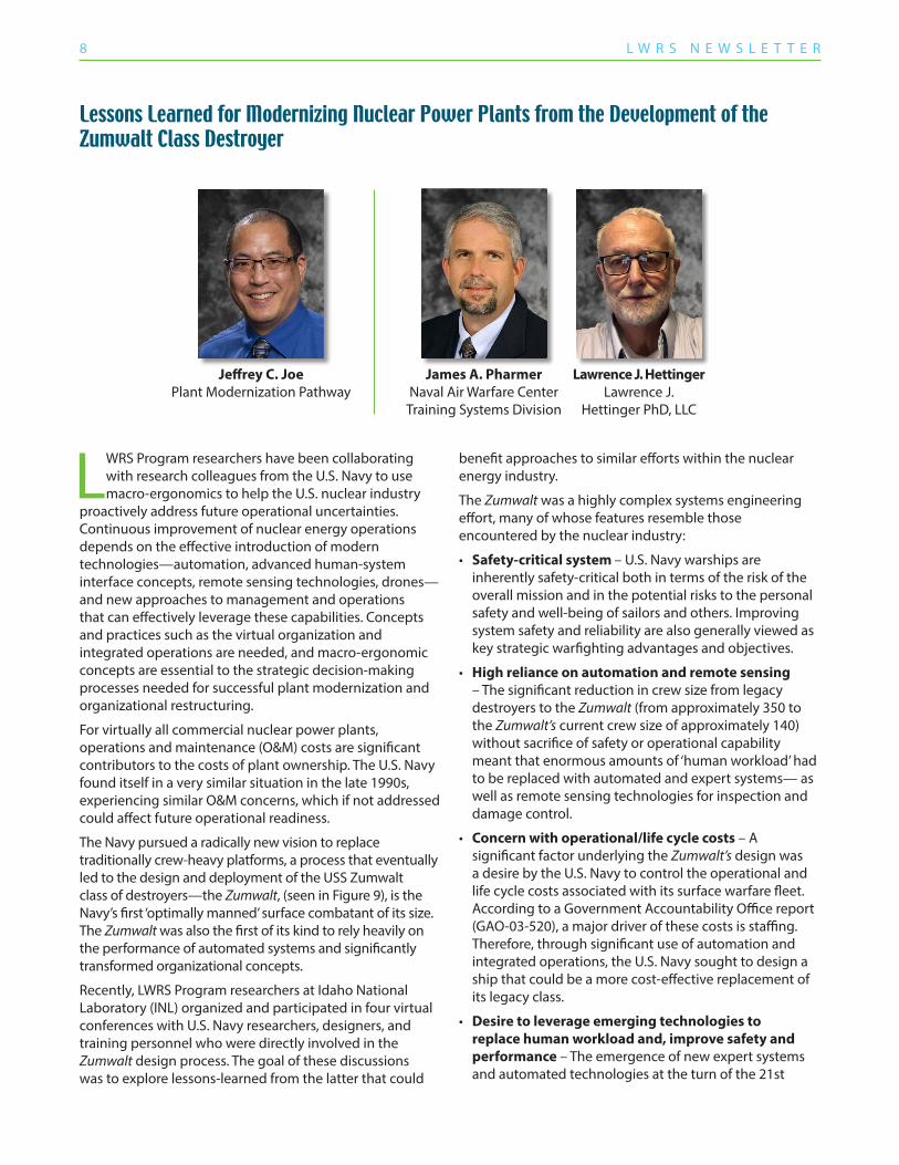
Figure 11. Overpressure at 1 km distance showing the MCA.
a preferred location for the steam bypass location and an upper rate of steam extraction that would not impact normal operation of the nuclear power plant. This provided a starting basis for a study of new risks introduced by the systems. Fault trees were developed for potential accident-initiating events, such as a steam rupture, a hydrogen leak, or a catastrophic detonation of a large volume of hydrogen in the vicinity of the nuclear power plant. A detonation could propagate a pressure wave that damages the plant’s reactor containment walls, power systems, and other critical infrastructure and services.
Detailed Hazard Analysis and ModelingThe likelihood and consequences of an initiating event on the reactor are being evaluated and used to update a PRA for a representative pressurized water reactor. The risks associated with the hydrogen plant have been assessed by hydrogen and fire experts at SNL, where a blast code with representative industry hydrogen leakage rate information was used for the pipes and components of the hydrogen plant to calculate overpressure event frequency and consequences for various nuclear power plant targets. The “maximum credible accident” (MCA), which is a measure of the accident event that is used to determine the vulnerability of specific targets, was calculated for a range of hydrogen plant leakage rates based on building containment assumptions and hydrogen-air mixture detonation types (e.g., a flame jet or a cloud detonation). Figure 11 plots the calculated overpressure curve at 1 km distance versus the amount of hydrogen detonated, along with the position of the MCA. The analysis found that only the switchyard components have a significant probability of failure based on the MCA value. None of the other critical targets in the nuclear power plant have fragility to the overpressure produced by the detonation. The result of this analysis indicates that it may be possible to position the hydrogen plant closer to the nuclear power plant, thereby saving money on the pipeline and decreasing thermal losses—all without compromising plant safety. This would also increase the dynamic response of the system, which would allow the nuclear/hydrogen plant to ramp-up
and ramp-down to send power as needed to the electricity grid to provide spinning or non-spinning reserve capacity. An evaluation of the safety effects relative to the separation distance from the nuclear power plant is now underway.
LicensingThe results of a preliminary PRA and hazardous analysis performed in 2019 indicate either U.S. Nuclear Regulatory Guide RG 1.174 [3] or Code of Federal Regulations 10 CFR 50.59 [4] could be workable approaches to licensing nuclear power plant operations that supply process heat to a hydrogen plant. An overall core damage frequency change was within the acceptable limits of the RG 1.174 pathway. However, based on an initial conservative design of the thermal hydraulic system, the frequency of transients adversely affected two “design basis accidents” by a percentage that was unacceptable for license provisions under 10 CFR 50.59. A more thorough design of the thermal energy extraction systems is now underway, which will likely reduce the frequency of system transients to a point that 10 CFR 50.59 can also be exercised for licensing FPOG.
References1. Evaluation of nonelectric Market Options for a Light-water
Reactor in the Midwest, INL/EXT-19-55090, Rev. 0, August 2019, and Preliminary Outlook on Markets for Integrated Energy Systems, INL/EXT-19-55913, Rev. 0, September 2019.
2. Light Water Reactor Sustainability Program Integrated Program Plan, INL-EXT-11-23452, Rev 8, May 2020.
3. U.S. Nuclear Regulatory Commission Regulatory Guide 1.174, An Approach for Using Probabilistic Risk Assessment in Risk-Informed Decision on Plant-Specific Changes to the Licensing Basis, August 2009, https://www.nrc.gov/docs/ML1009/ML100910006.pdf.
4. U.S. Code of Federal Regulations, § 50.59 Changes, Tests and Experiments, https://www.nrc.gov/reading-rm/doc-collections/cfr/part050/part050-0059.html.
Released Hydrogen Quantity (kg)
0.00 10 20 30 40 50
0.1
0.2
0.3
0.4
0.5
0.6
0.7
0.8
Over
pres
sure
at 1
km (p
si)Overpressure vs. DistanceMCA

10-GA50624-32
To submit information or suggestions, contact Cathy J. Barnard at [email protected].
Editor: Gordon Holt Designer: David Combs
Recent LWRS Program Reports
(Click on the report title to download the document.)
Materials Research Pathway• A Hybrid AI/ML and Computational Mechanics Based Approach for
Time-Series State and Fatigue Life Estimation of Nuclear Reactor Components
• Analysis of Deformation Localization Mechanisms in Highly Irradiated Austenitic Stainless Steel via In Situ Techniques
• Assessment of Grizzly Capabilities for Reactor Pressure Vessels and Reinforced Concrete Structures
• Cable Nondestructive Examination Online Monitoring for Nuclear Power Plants
• Evaluation of Critical Parameters to Model Stress Corrosion Crack Initiation in Alloy 600 and Alloy 182 in PWR Primary Water
• Intermediate-Term Thermal Aging Effect Evaluation for Grade 92 and 316L at the LWR Relevant Temperature
• Potential Life Extension Strategies for In-Service Degraded Cables
• Quantifying Micro-Galvanic Corrosion in Stainless Steels Activated by Post-Yielding Microstructures
• Sequential Versus Simultaneous Aging of XLPE and EPDM Nuclear Cable Insulation Subjected to Elevated Temperature and Gamma Radiation
Plant Modernization Pathway• An Applied Strategy for Using Empirical and Hybrid Models in Online
Monitoring
• Analysis and Planning Framework for Nuclear Plant Transformation
• Business Case Analysis for Digital, Safety-Related Instrumentation & Control System Modernizations
• Concept for Integrated Multi-Modal Online Piping Monitoring System along with Data Fusion and Advanced Data Analytical Algorithms using High-Resolution Fiber Optics Sensors
• Concrete Structure Health Monitoring Using Vibro-acoustic Testing and Machine Learning
• Hybrid Modeling of a Circulating Water Pump Motor
• Industry Engagement on Integrated Operations for Nuclear
• Markov Process to Evaluate the Value Proposition of a Risk-Informed Predictive Maintenance Strategy
• Report on the Use and Function of the Integrated Operations Capability Analysis Platform and the LWRS Innovation Portal
• Safety-Related Instrumentation & Control Pilot Upgrade Initial Scoping Phase Implementation Report and Lessons Learned
• Towards a Deeper Understanding of Automation Transparency in the Operation of Nuclear Plants
Risk-Informed Systems Analysis Pathway• Assessment of Verification and Validation Status – EMRALD and HUNTER
• Development and Application of a Risk Analysis Toolkit for Plant Resources Optimization
• Development of RELAP5-3D Modeling of Reactor Core Isolation Cooling (RCIC) System
• Fire Risk Investigation in 3D (FRI3D) Software and Process for Integrated Fire Modeling
• Integration of Data Analytics with Plant System Health Program
• R&D Roadmap to Enhance Industry Legacy Probabilistic Risk Assessment Methods and Tools
• Redundancy-guided System-theoretic Hazard and Reliability Analysis of Safety-related Digital Instrumentation and Control Systems in Nuclear Power Plants
• RISA Plant Reload Process Optimization: Development of Design Basis Accident Methods for Plant Reload License Optimization
• Risk-Informed ATF and FLEX Analysis for an Enhanced Resilient BWR Under Design-Basis and Beyond-Design-Basis Accidents
• Risk-informed Multi-Physics Best-Estimate Plus Uncertainties (BEPU) Application Development of RELAP5-3D Perturbation Model
• Terry Turbopump Expanded Operating Band Modeling and Simulation Efforts in Fiscal Year 2020 – Progress Report
Flexible Plant Operation & Generation Pathway• Flexible Plant Operation and Generation Probabilistic Risk Assessment
of a Light Water Reactor Coupled with a High-Temperature Electrolysis Hydrogen Production Plant
• Markets and Economics for Thermal Power Extraction from Nuclear Power Plants for Industrial Processes
• Preliminary Human-System Evaluation of Thermal Power Dispatch Concept of Operations
• Techno-Economic Analysis of Synthetic Fuels Pathways Integrated with Light Water Reactors
Physical Security Pathway• Economic Analysis of Physical Security at Nuclear Power Plants Security
at Nuclear Power Plants
• Integration of FLEX Equipment and Operator Actions in Plant Force-On-Force Models with Dynamic Risk Assessment
• Methodology and Application of Physical Security Effectiveness Based on Dynamic Force-on-Force Modeling