Rising Roadblockers.pdf · 1.1.22 Proximity Switch: ... 1.1.23 Loop Detector: This detector is used...
29
Transcript of Rising Roadblockers.pdf · 1.1.22 Proximity Switch: ... 1.1.23 Loop Detector: This detector is used...

���������� ������������
��������������� ��������������
�����������������������
�������������������������
�������������� �������

1
INDEX Page
1. GENERAL INFORMATION .......................................................................... .3
2. SYSTEM COMPONENTS ............................................................................. .5
2.1 Construction and Foundation ..................................................................................... .5
2.2 Control Cabinet ......................................................................................................... 12
2.3 Electrical and Electronics Components ......................................................................... 13
2.4 Hydraulic Units .......................................................................................................... 18
3. OPERATION INSTRUCTIONS .................................................................... 20
3.1 Taking the Road Blocker into Operation ............................................................................... 20
3.2 Operation of the Road Blocker .................................................................................... 22
4. MAINTENANCE .......................................................................................... 23
5. PRACTICAL TROUBLESHOOTING PROCEDURES ...................................... 24
6. HOW TO PUMP MANUALLY ....................................................................... 25
7. CE DECLERATION ...................................................................................... 26
8. ISO14001:2004 CERTIFICATE ............................................................................. 27
9. ISO9001:2008 CERTIFICATE ................................................................................ 28
�������������� �������

2
SYSTEM
SPECIFICATIONS
and
DATASHEET
�������������� �������

3
1. GENERAL INFORMATION
Road blockers are designed especially for entrance points which have a threat of vehicle
attack or for the ones that have high security requirements. If there is a threat of vehicle attack in
addition to the control of vehicle access in high security applications, hydraulic road blockers are the
unique solution and the most secure systems. Even though the attack is from high tonnage vehicles
with high speeds, it’s not possible for the vehicle to keep on moving because of the damage given to
front, wheels and the bottom of the vehicle.
Drive unit is hydraulic, but in case of power failure road blocker can be lowered or lifted
manually with the help of manual hand pumps and valves. With the help of PLC controlled electronics,
raise/lower function can be achieved by every kind of card readers, biometric readers like fingerprint
or hand shape, radio control, on/off key switch etc. Besides, safety accessories like photocells,
inductive loop detectors, flashing lights or red/green lights can be integrated to the system.
Picture 1. General View of Road blocker
1- Hydraulic Road blocker
2- Control Cabinet
3- Security Photocell(optional)
4- Red/Green LED Lights (30cm diameter,
on 2,5m height steel post.)
5- Flashing Lights (optional)
Picture 2. STOP Writing.
OPTIMA can write STOP onto HRR in every language .
�������������� �������
4
1.1 Standard features in HRR 4080
1.1.1 Height when raised: 800 mm
1.1.2 Width: 4000 mm
1.1.3 Weight (approximately): 1100-1600 kg
1.1.4 Depth of concrete pit (approximately): 1045 mm
1.1.5 Width of concrete pit (approximately): 1365 mm
1.1.6 Length of concrete pit (approximately): 2935 mm
1.1.7 Environmental durability: 3 times red oxide paint, 3 times painted yellow & red
stripes (‘STOP’ warning in the front)
1.1.8 Strength: Designed to K12 standards.
(Finite element analysis available upon request.) Any vehicle moving with 80Km/hour and
7.5 tons of weight, will be stopped and destroyed.
1.1.9 Axle Load : 50 tons
1.1.10 Structure : Heavy duty
1.1.11 Top Plate : Plain, painted to yellow with black stripes.
1.1.12 Type of Steel : S235/RAEX250-Quality 37 minimum
1.1.13 Red/green LED Traffic light: Available, 30cm diameter, steel post 2,5m
height and electrostatic ally powder coated to RAL 7032 (Optional)
1.1.14 Hinges : Heavy duty HARDENED AND OR STAINLES Steel AISI 303 Quality for
hydraulic cylinder connections and moving part of the blocker..
1.1.15 Bearing : Bronze
1.1.16 Power : 380 V, 3 Phase, 50-60 Hz
1.1.17 Power Failure : Manuel hand pump
1.1.18 Raise lower time : 4 seconds, in emergency 1.5 seconds.
1.1.19 Alarm : PLC programmable, sound and light.
1.1.20 Desktop keyboard : Raise, Lower, Emergency Stop, Key Operated, ‘Keyboard
in use’ light indicator.
1.1.21 Extra I/O at the PLC : Enough I/O’s to connect any card reader, arm barrier,
extra override keyboard etc. later on.
1.1.22 Proximity Switch: Available to sense the position of the blocker.
1.1.23 Loop Detector: This detector is used for safety
1.1.24 Uninterrupted Power Supply (UPS): To supply the power needed by the
electronic components for a limited time
1.1.25 Cooler/Heater: Standard
1.1.26 Cabinet: IP 55 with continuous ventilation.
1.1.27 Power : 4 KW, 1500 rpm
1.1.28 Environmental conditions : -20 °C and +75 °C, %100 non-condensing
humidity.
�������������� �������

5
Optional Accessories (In addition to the ones listed in ‘Standard Features’ section)
1. Flashing lights
2. Radio control receiver, transmitter and antenna
3. Safety photocell, stand and casing
4. Submersible Pump
5. Card Reader System
6. Uninterrupted Power Supply (UPS) to raise/lower the road blocker for a period of time in
case of no electricity.
2. SYSTEM COMPONENTS
2.1 Construction and Foundation
Main mechanical elements forming the construction are heavy duty, 12 mm anti-skid / plain
top plate, blocking construction and the frame consisting of 100 mm I, U and 100x100x3 mm box
beams. It’s made of steel S235JR / RAEX 250 – quality 37 at least. This sophisticated mechanical
design enables the road blocker to withstand 50 tons of axle loads, besides, in case of crash, linkage
bars transmit the impact directly to the foundation, therefore help to protect mechanism. A cushioned
cylinder powers the road blocker up as it pivots on multi-sealed bearings. The hinges are made of
hardened and stainless steel. Parts forming the drive unit, namely, piston, piston rod, reservoir,
solenoid or manual valves, pump, motor, etc. are very precisely manufactured so that they can stand
harsh environmental conditions. All the parts are hot dip galvanized (60 micrometers) / Rust-
Prevention (Epoxy Coated) painted in order to prevent rusting. Additionally the parts which stand
above the ground level are yellow-black painted.The hydraulic rising road blocker will be installed in
reinforced concrete foundation by M12 anchors.
�������������� �������
6
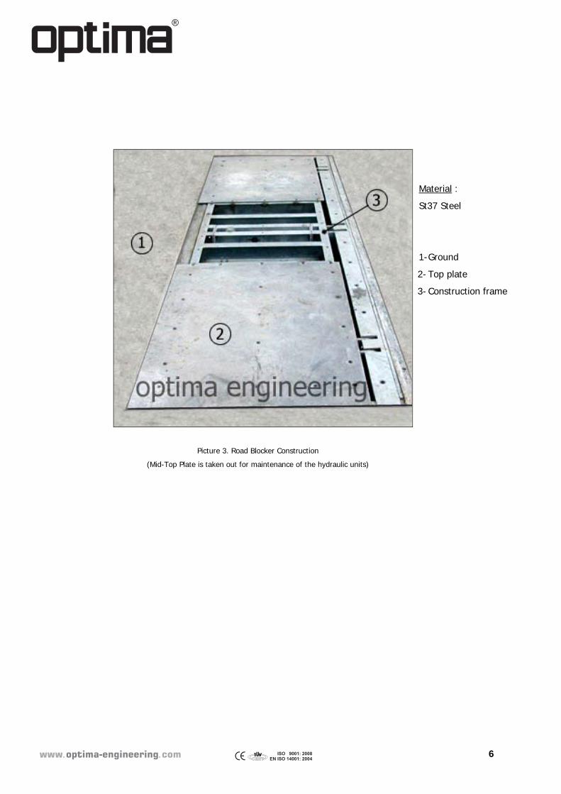
Picture 3. Road Blocker Construction
(Mid-Top Plate is taken out for maintenance of the hydraulic units)
Material :
St37 Steel
1- Ground
2- Top plate
3- Construction frame
�������������� �������
7
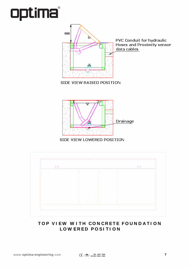
TOP VIEW W ITH CONCRETE FOUNDATION LOW ERED POSITION
�������������� �������
8
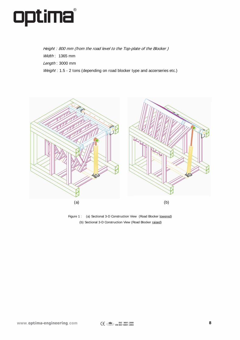
Height : 800 mm (from the road level to the Top-plate of the Blocker )
Width : 1365 mm
Length : 3000 mm
Weight : 1.5 - 2 tons (depending on road blocker type and accerseries etc.)
(a) (b)
Figure 1 : (a) Sectional 3-D Construction View (Road Blocker lowered)
(b) Sectional 3-D Construction View (Road Blocker raised)
�������������� �������

9
Figure 2 : (c) 3-D Construction View (Road Blocker closed)
Figure 3 : (d) 3-D Construction View - Front (Road Blocker raised)
�������������� �������

10
(e)
Figure 4 : (e) 3-D Construction - Isometric (Road Blocker raised)
�������������� �������

11
Sample Concrete Foundation Dimensions
SECTION A-ASECTION B-B
B
B
AA
4535
4035
3935
1965
1595
1365
150
200
190110
1365120
180
1357
1965
150
600
Ø200
100
25050
393550250
1357
200
100
600
Ø150 Ø1001877,5 180 1877,5
4535HIGH : 12 mm
DRENAIGE%3 SLOPE
HOSE INPUT
Figure 5. Road Blocker Concrete Foundation View
Depth : 1045 mm
Width : 1365 mm
Length : 4535
Wall thickness : 300 mm
Customer ‘must’ request a layout drawing for each project from the manufacturer as dimension may
vary in every application.
Fig.6 Road blocker electrical drawing
�������������� ������� �������������� �������

12
2.2 Control Cabinet
Material:
2 mm thick sheet metal (electrogalvanized, RAL 7032 electrostatically(epoxy) powder coated
and furnaced) for water-resistant outdoor applications.
2.5 mm thick sheet metal (electrogalvanized, RAL 7032 electrostatically(epoxy) powder coated
and furnaced) for inside hydraulic and electric group carriages
Dimensions : 120(h) cm x 115(w) cm x 75(L) cm (Cabinet may be manufactured in different dimensions according to requirements) The cabinet is fitted with espagnolet fastening and half europrofile cylinder.
Picture 4. Control Cabinet Views
1- Cabinet Side Cover 4- Open/Close Handle and Lock with Key 2- Air Circulation Opening with filter 5- Gasket 3- Cabinet Front Cover 6- Plate
�������������� �������

13
2.3 Electrical and Electronics Components
Control electronics utilized in hydraulic road blocker is PLC controlled. Raise/lower function can
be achieved by every kind of card readers, biometric readers like fingerprint or hand shape, radio
control, on/off switches or key switches etc. Besides, safety accessories like inductive loop detectors,
photocells, flashing lights or red/green lights can be integrated to control electronics very easily.
Power requirement of the hydraulic road blocker is 380 V 50~60 Hz.
Pic.5. Cabinet Control Panel Pic.6. Desktop Control Panel
1 Emergency Stop Stops the operation of the road blocker in case of emergency. If
pressed, the road blocker is locked and no comment could be given.
In order to return to the normal mode of operation, turn the button
clockwise until the switch releases itself
2 Phase R Shows the operation of the first phase cable of the three phases 380
VAC. If it does not light, no voltage on the first cable of the three
phases 380 VAC on the terminal and maintenance is needed.
3 Phase S Shows the operation of the second phase cable of the three phases
380 VAC. If it does not light, no voltage on the second cable of the
three phases 380 VAC on the terminal and maintenance is needed.
4 Phase T Shows the operation of the third phase cable of the three phases 380
VAC. If it does not light, no voltage on the third cable of the three
phases 380 VAC on the terminal and maintenance is needed.
5 Auto Up Raises the road blocker automatically. It is enough to push the
button ONCE in order to operate the road blocker from Cabinet
�������������� �������

14
Control Panel. No other comment could be given until the process is
accomplished.
6 Auto Down Lowers the road blocker automatically. It is enough to push the
Button ONCE in order to operate the road blocker from Cabinet
Control Panel.No other comment could be given until the process is
Accomplished.
7 Auto Down Lowers the road blocker automatically. It is enough to push the
button ONCE in order to operate the road blocker from Cabinet
Control Panel. No other comment could be given until the process is
accomplished.
8 Auto Up Raises the road blocker automatically. It is enough to push the
button ONCE in order to operate the road blocker from Desktop
(Override/Guard House) Control Panel. No other comment could be
given until the process is accomplished.
9 Emergency Stop Stops the operation of the road blocker in case of emergency. If
pressed, the road blocker is locked and no comment could be given.
In order to return to the normal mode of operation, turn the button
clockwise until the switch releases itself.
10 Local Enabled Shows that current Desktop (Override/Guard House) Control Panel is
in charge for the operation of the road blocker if this light in ON.
11 Keyboard: Off/On Depending on the priority of the Control Panel, this switch changes
the operating Control Panel. The priority is Override Desktop Panel,
Guard House Desktop Panel and Cabinet Control Panel from the most
prior to the least prior respectively.
�������������� �������

15
Picture 7. Electrical Components
1 Cabinet Control Panel Explained in the previous pages.
2 Main Fuse For the whole system.
3 Power Supply Output Fuse
4 +24VDC For the 24 VDC on the system
5 Phase Control Relay If the connection of phase cables is false, Lamp (As
side picture) will light on the Phase
Control Relay. If the connection of
phase cables is true, Lamp won’t light.
During the connection of the phase
cables, please be carefull. Relay. If the
connection of phase cables is true, Lamp
won’t light. During the connection of
the phase cables, please be carefull.
�������������� �������

16
6 Thermic Magnetic Switch Motor safety switch. If a problem occurs in the oil pump inside
the road blocker, the switch becomes 0 (zero) and cuts the
energy of the oil pump motor to be available for the
maintenance.
7 Contactor Drives the motor
8 PLC 24 VDC, Password protected, programmable software PLC
operated PLC card user interface. 12 inputs and 8 outputs are
used. For the further additions and modifications of the
system, 4 inputs and 2 outputs is available. (Total 16 input/10
Output).
9 Relay Group PLC output protection relays.
A- Motor
B- Solenoid Valf (up)
C- Solenoid Valf (down)
D- Traffic Lamp
E- Flashing Lamp
10 +24 VDC
11 GND
12 Loop Dedector For Safety
13 Therminal Goup Connects electric (energy) connection of the whole system.
A- 3 Phase 380 VAC input
B- Motor input/output
C- Drainage Pump Output
D- Flashor Lamp Output
E- +24 VDC
F- Solenoid Valve Output
G- Keyboard Input
H- Proximity Sensor Input
I- Traffic Light Output
J- Loop Detector Antenna Input
14 Power Supply AC/DC Converter. If the energy is supplied to the system from
three phases 220/380 VAC, this device changes the voltage to
24 VDC in order to supply power to some of the components
in the system.
�������������� �������

17
1 2 3 4 5 6 7 8 9 10 11 12 13 14 15 16 17 18 19 20 21 22 23 24 25 26 27 28 29 30 31 32 33 34 35 36 37 38 39 40 41 42 43 44 45
I1 I3 I4 I5 I6 I7 I8 I9 IA IB IC -- +
Q1 Q2 Q3 Q4 Q5 Q6 Q7 Q8
T1 T2 T3 T1 T2 T3
L1 L2 L3 L1 L2 L3L1 L2 L3
T1 T2 T3
STOP START
MOTORTHERMIC CONTACTOR CONTACTOR
MOTOR HEATER
LC1D09M7 LC1D09M7
L1 L2L3
14
12
A2 A1
11
14 14 14 14
12 12 12 12
A2 A2 A2 A2A1 A1 A1 A1
11 11 11 11
R
ELA
Y
R
EL
AY
R
EL
AY
R
EL
AY
R
EL
AY
1114 12
F1 F2 F3 F4 F5
14
12
A2 A1
11
R
EL
AY
14
12
A2 A1
11
R
EL
AY
A1
A2
A1
A2
L N -V +V
PLC SR2A201BD
LOOPDETECTOR
RD
RD RD
RD RD
BK
BK
BK
BK BK
L1 L2 L3
R S T MP
TERMINAL BLOCKS
INPUT POWER (380V 3 )
STP
R
STP
R
STP
R
STP
R
STP
R
STP
R
STP
R
STP
R
STP
R
STP
R
STP
R
STP
R
STP
R
STP
R
STP
R
MOTOR
HYDRAULICMOTOR
U V W
DRAINAGEPUMP
HEATER
OILCOOLERFAN SOLENOID
UP DOWN
KEYBOARD(INTERNALVIEW)
CONNECTIONDIAGRAM
AUTOUP
AUTODN
EM.STOP
PROXIMITYSENSOR
BR BL BK
RED
GREEN
TRAFFICLIGHT
LOOPANTENNA
CABINETFAN
BG
BG
BG BG
BG
BG BG
BG
BG
BG
BG
BG
BG
BG BG
BG
BG BG
BG
BG
BG BG
BG
BG
BG
BG
BG
BGBL BL
BL
BL
BL
BL
BLRD
RD
RD RD
BK
BK
BK
BK
BK BK
3015
60
45
HEATERTHERMOSTAT
P
HA
SE
R
EL
AY
BG
BG
BG BG
BG
BG BG
RD
BG
BG
APC
UPS
INPUT
OUTPUT
ACCU.UP
KEY.SWITCH ACCU.
DN
PRESSURESWITCH
SOLENOID
ACCUMULATORSOLENOID
28 29 30 31 32 33 34 35
24VDCPOWERSUPPLY
6.5A
100
-120
VAC
4A 2
00-2
40VA
C
50
/60
Hz
SP-320-24
+V ADJ
DC ADJ+24V 14.6A
BR Y/G
BL
BR Y/G
BL
Fig.7 Electrical Connection Drawing
�������������� �������

18
2.4 Hydraulic Components
There are two pumps in the hydraulic system: Electric motor coupled gear pump (17 cc) and
manual operated hand pump. The first one is the default used pump in the system. The hand pump is
installed in case there is no power the gear pump does not work. When the direction control valves
are in tandem positions, the oil is pumped back to the reservoir through the pressure relief valve.
The oil level in the hydraulic system could be checked with the help of the “Oil Level Gauge”
and oil could be added through “Oil Reservoir Plug”.
Picture 8. Hydraulic Group
1 Electric Motor
2 Oil Reservoir Plug (to fill the tank)
3 Manometer
4 Direction Control Valve
5 Aluminium Block (For hose connection)
6 Manuel Hand Pump
7 Oil Dirtiness Gauge
8 Oil Level and Temperature Gauge
9 Tank
10 Oil Evacuation Plug
�������������� �������

19
OPERATION and
MAINTENANCE
�������������� �������

20
3. OPERATION INSTRUCTIONS
3.1 Taking the Road Blocker Into Operation 1. Open the control cabinet. Meanwhile unscrew the 4 pcs of holding rings from the roadblocker’ s top plate.
Figure : 9/1 Figure : 9/2
Figure : 9/3 Figure : 9/4
Figure : 9/5
�������������� �������

21
2. Connect the hoses coming from the hydraulic cylinder with the hydraulic system in the
cabinet.
3. If there is a Drainage Pump in the Road Blocker System, connect the electric power cable
to the terminal.
4. If there is a Red/Green Traffic Light in the Road Blocker System, connect the electric
power cable of the Red/Green Traffic Light to the terminal.
5. If there is a Loop Detector in the Road Blocker System, connect the antenna cables of the
Loop dedector to the terminal.
6. If there are Radio control receiver, transmitter and antenna in the Road Blocker System,
connect the electric power cable of it to the terminal.
7. If there are Safety photocell, stand and casing in the Road Blocker System, connect the
electric power and data cables of Safety Photocell to the terminal.
8. If there is a Card Reader System in the Road Blocker System, connect the electric power
and data cables of Card Reader System to the terminal.
9. Make sure that fuses on the Cabinet Panel (Picture 7 No:2, No:3) are ON (upward
position).
10. Make sure the emergency stop buttons on the Cabinet Control Panel and Guard House
Desktop Panel (Picture 5 No: 1; Picture 6 No: 9) are not pressed.
11. Initially, there will be no oil in the hydraulic system, therefore fill the oil reservoir with
Shell Thellus 46 or equivalent. Check oil level from the gauge (Picture 8, No: 8) on the
oil reservoir (Picture 8, No: 9). It must show ‘ full ’ .
12. Make sure that Motor safety switch on the Cabinet Panel (Picture 7, No: 4) are ON.
13. Connect the three phase 380 VAC cables to the terminal.( Picture 7, Item 13-A)
14. Make sure that all three phase check lights (Phase R, Phase S, Phase T) on the Cabinet
Control Panel (Picture 5, No: 2, 3, 4) are ON.
�������������� �������

22
3.2 Operation of the Road Blocker
Depending on the position of the Local/Remote Switch on the Override Desktop Panel and
Guard House Desktop Panel, either Override Desktop Panel or Guard House Desktop Panel or Cabinet
Control Panel could control the Road Blocker. For each Road Blocker, only ONE panel could be in
charge, i.e. two panels could not operate the road blocker at the same time.
Case 1) The Guard House Desktop Control Panel is in Charge: If the Local/Remote Switch of
the.Desktop Control Panel is on the “Enable” position (switch is heading to the RIGHT) the
“Local Enabled Light” on the Guard House Desktop Control Panel becomes ON which
means that the Guard House Desktop Control Panel is in charge and Cabinet Control Panel
could not operate the Road Blocker.
Case 2) The Cabinet Control Panel is in Charge: If the Local/Remote Switch of the Desktop
Control Panel is on the ‘Disable’ position (switch is heading to the LEFT), the Cabinet Control
Panel is in charge.
For each case, the operation of the road blocker is as follows:
Raising of the Road blocker is done automatically. In order to raise it automatically, push
“Auto Up” button (Picture 5 No: 5, Picture 6 No: 8) ONCE.
Lowering of the Road blocker is done automatically. In order to raise it automatically, push
“Auto Down” button (Picture 5 No: 6, Picture 6 No: 7) ONCE.
Unless a successive command is sent, the motor will stop in 4 seconds.
Depending on the customer desire, “DEAD-MAN BUTTON” could be added to the system. In
that case, in order to raise and lower the road blocker, either automatically or manually,
Guard House Desktop Control Panel and the dead-man button MUST be pushed at the same
time; otherwise the road blocker could not be operated from the guard house. This function is
added to the system in order to prevent the road blocker from being operated by people other
than the guard staff in case of emergency.
Depending on the customer desire, inductive loop detector(s) could be added to the system.
These devices work on the “PULSE ON EXIT” or ‘SAFETY LATCH’ principle, i.e. when the
vehicle leaves the loop detectors magnetic area, it sends the PLC controller a pulse in order to
inform it about the vehicle’s position or it sends a signal as long as there is a vehicle on the
loop antenna. According to the design of the control logic, the road blocker could be raised
and lowered automatically even without using the desktop panels.
�������������� �������
23
Depending on the customer desire, card reader system could be added to the system.
According to the design of the control logic, the road blocker could be raised and lowered
automatically even without using the desktop panels with the help of the pulse sent by the
card reader system.
4. MAINTENANCE
Oil Check
Oil Used: Shell Thellus 46 or equivalent
First oil change to be made after 500 working hours, next changes to be made after every
5000 working hours.
Filters Check
Filters to be changed at every oil change.
Oil Leakage Check
System to be eye-controlled for oil leakage once in every 3 months.
Piston to be eye-controlled if there is any leakage once a year.
Pressure Check
Manometer pressure values must be checked at every leakage control to see if there is
any deviation from the values stated by the manufacturer.
Maintenance Staff
All system controls to be made by qualified technical staff only.
Only original equipment manufactured or recommended by the manufacturer to be used
at repair and/or maintenance procedures.
�������������� �������

24
5. PRACTICAL TROUBLESHOOTING PROCEDURES
If there is no movement observed after pressing auto or manual raise/lower buttons;
Make sure the emergency stop buttons on the Cabinet Control Panel and Guard
House Desktop Panel (Picture 5 No: 1; Picture 6 No: 9) are not pressed.
Make sure that fuses on the Cabinet Panel (Picture 7, No: 2and 3) are ON (upward
position).
Make sure that Motor safety switch on the Cabinet Panel (Picture 7, No: 4) are ON.
Make sure that all three phase check lights (Phase R, Phase S, Phase T) on the
Cabinet Control Panel (Picture 5, No: 4, 5, 6) are ON.
If there are unexpected behaviors in system, quickly stop the system by pressing one of
the emergency stop buttons on the Cabinet Control Panel, Override Desktop Panel and
Guard House Desktop Panel (Picture 5 No: 1; Picture 6 No: 9).
In case of power failure, road blocker could ONLY be controlled by the cabinet control
panel due to the battery in the cabinet supplies the needed power for the electronics and
in case of the battery power shortage, the hand pump is used to raise/lower the road
blocker manually.
�������������� �������

25
6. HOW TO PUMP MANUALLY
Insert manual pump arm into the slot and pump manually (Figure 13).
Push the pressure direction rod to the right side of direction control valve for
raising and to the left side of direction control valve for lowering as shown in the
picture.
Pump the system manually by hand as shown in the pictures.
Figure 13-A.Raising Position
Figure 13-A.Lowering Position
**If the system is not still running after all these controls, please contact with the
manufacturer.
�������������� �������

26
DECLARATION OF CONFORMITY FOR MACHINES (DIRECTIVE 98 / 37 EEC, ATTACHMENT II , PART B)
Manufacturer: OPTİMA MÜHENDİSLİK LİMİTED ŞİRKETİ KERESTECİLER SANAYİ SİTESİ 3. CADDE NO:8 SARAY 06980 KAZAN / ANKARA/ TÜRKİYE Declares that the products,
HRR SERIES HYDRAULIC RISING ROADBLOCKERS HRB SERIES HYDRAULIC RISING BOLLARDS HDAB SERIES HYDRAULIC DROP ARM BARRIERS
are constructed to be incorporated in a machine or to be assembled with other machinery to construct a machine considered modified by the directive 98 / 37 EEC are in confirmity with the regulations of the following EEC directives.
Directive 98 / 37 EEC directive for machines Directive 73 / 23 EEC and directive 93 / 68 EEC low voltage Directive 89 / 336 EEC and directive 92 / 31 EEC and directive 93 / 68 EEC
electromagnetic compatibility. And also are in confirmity with the following national standards.
- TS – EN 292-1 / January 1996 Standard - TS – EN 292-2 / January 1996 Standard - TS – EN 563 / April 1997 Standard - TS – EN 418 / November 1995 Standard - TS – EN 60204-3-1 / December 1995 Standard - TS – EN 50082-1 / April 1995 Standard - TS – EN 50082-2 / February 1998 Standard - TS – EN 60000-4-2 / April 1997 Standard
4 April 2001 Ankara İsmail Tamer ÜLGEN TURKEY President Mechanical Engineer, B. Sc.
GUARANTEE CERTIFICATE
The product that you have bought is under guarantee for any kind of manufacturing and material defects for 1 (one) year from
the beginning of the bill date. Installation and usage damages are out of guarantee.
OPTIMA ENGINEERING Co.Ltd.

27

28