Riscv Spec
32
The RISC-V Instruction Set Manual Volume I: Base User-Level ISA Version 1.0 Andrew Waterman, Yunsup Lee, David Patterson, Krste Asanovi´ c CS Division, EECS Department, University of California, Berkeley {waterman|yunsup|pattrsn|krste}@eecs.berkeley.edu August 22, 2011 1 Introduction RISC-V is a new instruction set architecture (ISA) designed to support computer architecture research and education. Our goals in defining RISC-V include: • Provide a realistic but open ISA that captures important details of commercial general- purpose ISA designs and that is suitable for direct hardware implementation. • Provide a small but complete base ISA that avoids “over-architecting” for a particular mi- croarchitecture style (e.g., microcoded, in-order, decoupled, out-of-order) or implementation technology (e.g., full-custom, ASIC, FPGA), but which allows efficient implementation in any of these. • Support both 32-bit and 64-bit address space variants for applications, operating system kernels, and hardware implementations. • Support highly-parallel multicore or manycore implementations, including heterogeneous mul- tiprocessors. • Support an efficient dense instruction encoding with variable-length instructions, improving performance and reducing energy and code size. • Support the revised 2008 IEEE 754 floating-point standard. • Be fully virtualizable. • Be simple to subset for educational purposes and to reduce complexity of bringing up new implementations. • Support experimentation with user-level ISA extensions and specialized variants. • Support independent experimentation with new supervisor-level ISA designs. This manual is structured into two volumes. This volume covers the base user-level ISA design and provides examples of possible ISA extensions. The second volume provides examples of supervisor- level ISA design. This manual represents only a snapshot of the RISC-V ISA, which is still under active development; some aspects of the instruction set may change in future revisions. Commentary on our design decisions is formatted as in this paragraph, and can be skipped if the reader is only interested in the specification itself. The name RISC-V was chosen to represent the fifth major RISC ISA design from UC Berkeley (RISC-I, RISC-II, SOAR, and SPUR were the first four). We also pun on the use of the Roman numeral “V” to signify “variations” and “vectors”, as support for a range of architecture research, including various data-parallel accelerators, is an explicit goal of the ISA design. Our intent is to provide a long-lived open ISA with significant infrastructure support, includ- ing documentation, compiler tool chains, operating system ports, reference SAME simulators, cycle-accurate FAME-7 FPGA simulators, high-performance FPGA computers, efficient ASIC
Transcript of Riscv Spec

The RISC-V Instruction Set ManualVolume I: Base User-Level ISA
Version 1.0
Andrew Waterman, Yunsup Lee, David Patterson, Krste AsanovicCS Division, EECS Department, University of California, Berkeley{waterman|yunsup|pattrsn|krste}@eecs.berkeley.edu
August 22, 2011
1 Introduction
RISC-V is a new instruction set architecture (ISA) designed to support computer architectureresearch and education. Our goals in defining RISC-V include:
• Provide a realistic but open ISA that captures important details of commercial general-purpose ISA designs and that is suitable for direct hardware implementation.
• Provide a small but complete base ISA that avoids “over-architecting” for a particular mi-croarchitecture style (e.g., microcoded, in-order, decoupled, out-of-order) or implementationtechnology (e.g., full-custom, ASIC, FPGA), but which allows efficient implementation in anyof these.
• Support both 32-bit and 64-bit address space variants for applications, operating systemkernels, and hardware implementations.
• Support highly-parallel multicore or manycore implementations, including heterogeneous mul-tiprocessors.
• Support an efficient dense instruction encoding with variable-length instructions, improvingperformance and reducing energy and code size.
• Support the revised 2008 IEEE 754 floating-point standard.
• Be fully virtualizable.
• Be simple to subset for educational purposes and to reduce complexity of bringing up newimplementations.
• Support experimentation with user-level ISA extensions and specialized variants.
• Support independent experimentation with new supervisor-level ISA designs.
This manual is structured into two volumes. This volume covers the base user-level ISA design andprovides examples of possible ISA extensions. The second volume provides examples of supervisor-level ISA design. This manual represents only a snapshot of the RISC-V ISA, which is still underactive development; some aspects of the instruction set may change in future revisions.
Commentary on our design decisions is formatted as in this paragraph, and can be skipped if thereader is only interested in the specification itself. The name RISC-V was chosen to representthe fifth major RISC ISA design from UC Berkeley (RISC-I, RISC-II, SOAR, and SPUR werethe first four). We also pun on the use of the Roman numeral “V” to signify “variations”and “vectors”, as support for a range of architecture research, including various data-parallelaccelerators, is an explicit goal of the ISA design.
Our intent is to provide a long-lived open ISA with significant infrastructure support, includ-ing documentation, compiler tool chains, operating system ports, reference SAME simulators,cycle-accurate FAME-7 FPGA simulators, high-performance FPGA computers, efficient ASIC
2 RISC-V Specification
implementations of various target platform designs, configurable processor generators, architec-ture test suites, and teaching materials. Initial versions of all of these have been developed orare under active development. This material is to be made available under open licenses (eithermodified BSD or GPL/LGPL).
2 Base User-Level ISA
This section defines the standard base user-level ISA, which has two variants, RV32 and RV64,providing 32-bit or 64-bit user-level address spaces respectively. Hardware implementations andoperating systems might provide only one or both of RV32 and RV64 for user programs. The ISAmay be subset by a hardware implementation, but opcode traps and software emulation must thenbe used to implement functionality not provided by hardware. The base ISA may be extended withnew instructions, but the base instructions cannot be redefined. Several standard extensions havebeen defined and are described in subsequent sections.
Although 64-bit address spaces are a requirement for larger systems, we believe 32-bit addressspaces will remain adequate for many embedded and client devices for decades to come and willbe desirable to lower memory traffic and energy consumption. In addition, 32-bit address spacesare sufficient for educational purposes.
2.1 Base Programmers’ Model
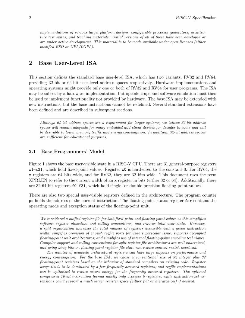
Figure 1 shows the base user-visible state in a RISC-V CPU. There are 31 general-purpose registersx1–x31, which hold fixed-point values. Register x0 is hardwired to the constant 0. For RV64, thex registers are 64 bits wide, and for RV32, they are 32 bits wide. This document uses the termXPRLEN to refer to the current width of an x register in bits (either 32 or 64). Additionally, thereare 32 64-bit registers f0–f31, which hold single- or double-precision floating-point values.
There are also two special user-visible registers defined in the architecture. The program counterpc holds the address of the current instruction. The floating-point status register fsr contains theoperating mode and exception status of the floating-point unit.
We considered a unified register file for both fixed-point and floating-point values as this simplifiessoftware register allocation and calling conventions, and reduces total user state. However,a split organization increases the total number of registers accessible with a given instructionwidth, simplfies provision of enough regfile ports for wide superscalar issue, supports decoupledfloating-point unit architectures, and simplifies use of internal floating-point encoding techniques.Compiler support and calling conventions for split register file architectures are well understood,and using dirty bits on floating-point register file state can reduce context-switch overhead.
The number of available architectural registers can have large impacts on performance andenergy consumption. For the base ISA, we chose a conventional size of 32 integer plus 32floating-point registers based on the behavior of standard compilers on existing code. Registerusage tends to be dominated by a few frequently accessed registers, and regfile implementationscan be optimized to reduce access energy for the frequently accessed registers. The optionalcompressed 16-bit instruction format mostly only accesses 8 registers, while instruction-set ex-tensions could support a much larger register space (either flat or hierarchical) if desired.

Copyright (c) 2010, 2011, The Regents of the University of California. All rights reserved. 3
XPRLEN-1 0 63 0
x0 / zero f0
x1 / ra f1
x2 f2
x3 f3
x4 f4
x5 f5
x6 f6
x7 f7
x8 f8
x9 f9
x10 f10
x11 f11
x12 f12
x13 f13
x14 f14
x15 f15
x16 f16
x17 f17
x18 f18
x19 f19
x20 f20
x21 f21
x22 f22
x23 f23
x24 f24
x25 f25
x26 f26
x27 f27
x28 f28
x29 f29
x30 f30
x31 f31
XPRLEN 64XPRLEN-1 0 31 0
pc fsr
XPRLEN 32
Figure 1: RISC-V base user-level programmer state.
4 RISC-V Specification
2.2 Instruction Length Encoding
The base RISC-V ISA has fixed-length 32-bit instructions that must be naturally aligned on 32-bit boundaries. However, the RISC-V encoding scheme is designed to support ISA extensionswith variable-length instructions, where each instruction can be any number of 16-bit instructionparcels in length and parcels are naturally aligned on 16-bit boundaries. A standard compressedISA extension described in the following section reduces code size by providing compressed 16-bitinstructions and relaxes the alignment constraints to allow all instructions (16 bit and 32 bit) tobe aligned on any 16-bit boundary to improve code density.
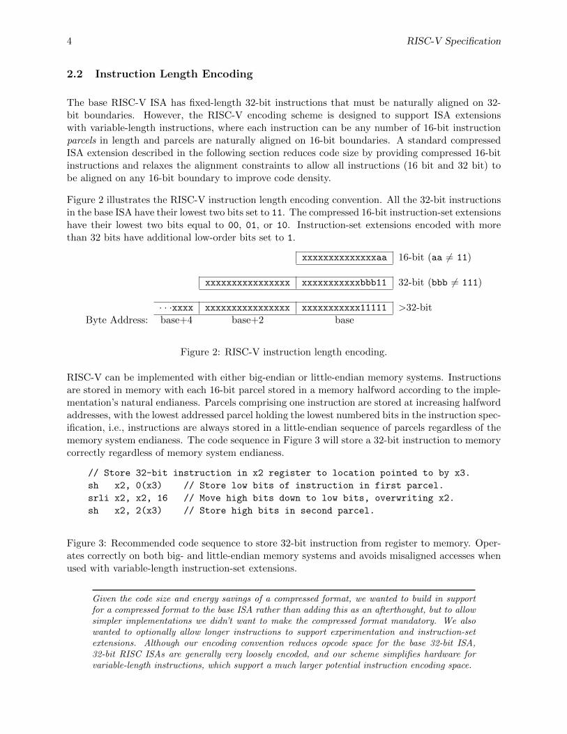
Figure 2 illustrates the RISC-V instruction length encoding convention. All the 32-bit instructionsin the base ISA have their lowest two bits set to 11. The compressed 16-bit instruction-set extensionshave their lowest two bits equal to 00, 01, or 10. Instruction-set extensions encoded with morethan 32 bits have additional low-order bits set to 1.
xxxxxxxxxxxxxxaa 16-bit (aa 6= 11)
xxxxxxxxxxxxxxxx xxxxxxxxxxxbbb11 32-bit (bbb 6= 111)
· · ·xxxx xxxxxxxxxxxxxxxx xxxxxxxxxxx11111 >32-bitByte Address: base+4 base+2 base
Figure 2: RISC-V instruction length encoding.
RISC-V can be implemented with either big-endian or little-endian memory systems. Instructionsare stored in memory with each 16-bit parcel stored in a memory halfword according to the imple-mentation’s natural endianess. Parcels comprising one instruction are stored at increasing halfwordaddresses, with the lowest addressed parcel holding the lowest numbered bits in the instruction spec-ification, i.e., instructions are always stored in a little-endian sequence of parcels regardless of thememory system endianess. The code sequence in Figure 3 will store a 32-bit instruction to memorycorrectly regardless of memory system endianess.
// Store 32-bit instruction in x2 register to location pointed to by x3.
sh x2, 0(x3) // Store low bits of instruction in first parcel.
srli x2, x2, 16 // Move high bits down to low bits, overwriting x2.
sh x2, 2(x3) // Store high bits in second parcel.
Figure 3: Recommended code sequence to store 32-bit instruction from register to memory. Oper-ates correctly on both big- and little-endian memory systems and avoids misaligned accesses whenused with variable-length instruction-set extensions.
Given the code size and energy savings of a compressed format, we wanted to build in supportfor a compressed format to the base ISA rather than adding this as an afterthought, but to allowsimpler implementations we didn’t want to make the compressed format mandatory. We alsowanted to optionally allow longer instructions to support experimentation and instruction-setextensions. Although our encoding convention reduces opcode space for the base 32-bit ISA,32-bit RISC ISAs are generally very loosely encoded, and our scheme simplifies hardware forvariable-length instructions, which support a much larger potential instruction encoding space.
Copyright (c) 2010, 2011, The Regents of the University of California. All rights reserved. 5
A base implementation need only hold the most-significant 30 bits in instruction caches (a6.25% saving). On instruction cache refills, any instructions encountered with either low bit clearshould be recoded into trap instructions before storing in the cache to preserve illegal instructiontrap behavior.
We have to fix the order in which parcels are stored in memory, independent of memorysystem endianess, to ensure that the length-encoding bits always appear first in halfword addressorder. This allows the length of a variable-length instruction to be quickly determined by aninstruction fetch unit by examining only the first few bits of the first 16-bit instruction parcel.The parcel ordering could have been fixed to be either big-endian (most-significant parcel first) orlittle-endian (least-significant parcel first). We chose to fix the parcel order to be little-endian, aslittle-endian systems are currently dominant commercially (all x86 systems; iOS, Android, andWindows for ARM). Once we had decided to fix on a little-endian instruction parcel ordering,this naturally led to placing the length-encoding bits in the LSB positions of the instructionformat to avoid breaking up opcode fields.
2.3 Base Instruction Formats
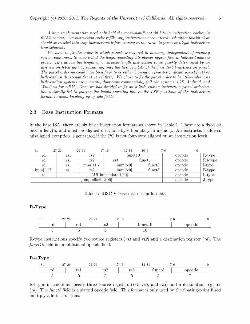
In the base ISA, there are six basic instruction formats as shown in Table 1. These are a fixed 32bits in length, and must be aligned on a four-byte boundary in memory. An instruction addressmisaligned exception is generated if the PC is not four-byte aligned on an instruction fetch.
31 27 26 22 21 17 16 12 11 10 9 7 6 0
rd rs1 rs2 funct10 opcode R-typerd rs1 rs2 rs3 funct5 opcode R4-typerd rs1 imm[11:7] imm[6:0] funct3 opcode I-type
imm[11:7] rs1 rs2 imm[6:0] funct3 opcode B-typerd LUI immediate[19:0] opcode L-type
jump offset [24:0] opcode J-type
Table 1: RISC-V base instruction formats.
R-Type
31 27 26 22 21 17 16 7 6 0
rd rs1 rs2 funct10 opcode
5 5 5 10 7
R-type instructions specify two source registers (rs1 and rs2) and a destination register (rd). Thefunct10 field is an additional opcode field.
R4-Type
31 27 26 22 21 17 16 12 11 7 6 0
rd rs1 rs2 rs3 funct5 opcode
5 5 5 5 5 7
R4-type instructions specify three source registers (rs1, rs2, and rs3) and a destination register(rd). The funct5 field is a second opcode field. This format is only used by the floating-point fusedmultiply-add instructions.
6 RISC-V Specification
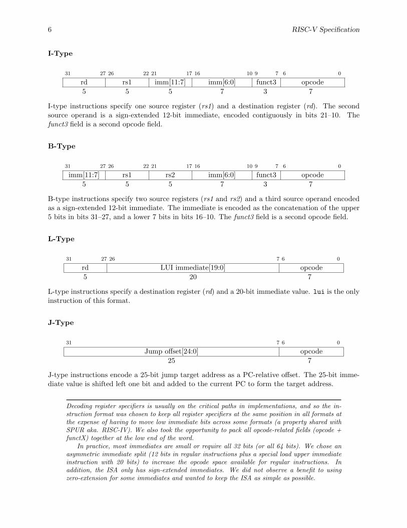
I-Type
31 27 26 22 21 17 16 10 9 7 6 0
rd rs1 imm[11:7] imm[6:0] funct3 opcode
5 5 5 7 3 7
I-type instructions specify one source register (rs1) and a destination register (rd). The secondsource operand is a sign-extended 12-bit immediate, encoded contiguously in bits 21–10. Thefunct3 field is a second opcode field.
B-Type
31 27 26 22 21 17 16 10 9 7 6 0
imm[11:7] rs1 rs2 imm[6:0] funct3 opcode
5 5 5 7 3 7
B-type instructions specify two source registers (rs1 and rs2) and a third source operand encodedas a sign-extended 12-bit immediate. The immediate is encoded as the concatenation of the upper5 bits in bits 31–27, and a lower 7 bits in bits 16–10. The funct3 field is a second opcode field.
L-Type
31 27 26 7 6 0
rd LUI immediate[19:0] opcode
5 20 7
L-type instructions specify a destination register (rd) and a 20-bit immediate value. lui is the onlyinstruction of this format.
J-Type
31 7 6 0
Jump offset[24:0] opcode
25 7
J-type instructions encode a 25-bit jump target address as a PC-relative offset. The 25-bit imme-diate value is shifted left one bit and added to the current PC to form the target address.
Decoding register specifiers is usually on the critical paths in implementations, and so the in-struction format was chosen to keep all register specifiers at the same position in all formats atthe expense of having to move low immediate bits across some formats (a property shared withSPUR aka. RISC-IV). We also took the opportunity to pack all opcode-related fields (opcode +functX) together at the low end of the word.
In practice, most immediates are small or require all 32 bits (or all 64 bits). We chose anasymmetric immediate split (12 bits in regular instructions plus a special load upper immediateinstruction with 20 bits) to increase the opcode space available for regular instructions. Inaddition, the ISA only has sign-extended immediates. We did not observe a benefit to usingzero-extension for some immediates and wanted to keep the ISA as simple as possible.

Copyright (c) 2010, 2011, The Regents of the University of California. All rights reserved. 7
Major Opcode Map
Table 2 shows a map of the major opcodes for the base ISA.
inst[4:2] 000 001 010 011 100 101 110 111inst[6:5] (> 32)
00 LOAD LOAD-FP OP-IMM OP-IMM-3201 STORE STORE-FP AMO MISC-MEM OP LUI OP-3210 MADD MSUB NMSUB NMADD OP-FP11 BRANCH J JALR JAL SYSTEM
Table 2: RISC-V base opcode map, inst[1:0]=11

8 RISC-V Specification
2.4 Load and Store Instructions
RISC-V provides a byte-addressed user memory address space and is a load-store architecture,where only load and store instructions access memory and arithmetic instructions only operate onCPU registers. The memory system can be either big-endian or little-endian depending on theimplementation. Byte addresses are 64 bits wide for RV64, and 32 bits wide for RV32.
31 27 26 22 21 17 16 10 9 7 6 0
rd rs1 imm[11:7] imm[6:0] funct3 opcode
5 5 5 7 3 7dest base offset[11:0] width LOADdest base offset[11:0] width LOAD-FP
31 27 26 22 21 17 16 10 9 7 6 0
imm[11:7] rs1 rs2 imm[6:0] funct3 opcode
5 5 5 7 3 7offset[11:7] base src offset[6:0] width STOREoffset[11:7] base src offset[6:0] width STORE-FP
Load and store instructions transfer a value between the registers and memory. Loads are encodedin the I-type format, and stores are B-type. The effective byte address is obtained by addingregister rs1 to the sign-extended immediate. Loads write to register rd a value in memory. Storeswrite to memory the value in register rs2.
The LD instruction loads a 64-bit value from memory into register rd for RV64. LD is illegal forRV32. The LW instruction loads a 32-bit value from memory for RV32, and sign-extends thisto 64 bits before storing it in register rd for RV64. The LWU instruction, on the other hand,zero-extends the 32-bit value from memory for RV64, but is illegal for RV32. LH and LHU aredefined analogously for 16-bit values, as are LB and LBU for 8-bit values. The SD, SW, SH, andSB instructions store 64-bit, 32-bit, 16-bit, and 8-bit values in register rd to memory, with SD onlybeing valid for RV64.
The FLD instruction loads a 64-bit double-precision floating-point value from memory into floating-point register rd, and the FLW instruction loads a 32-bit single-precision floating-point value. FSDand FSW store double- and single-precision values, respectively, from floating-point registers tomemory.
For best performance, the effective address for all loads and stores should be naturally aligned foreach data type (i.e., on an eight-byte boundary for 64-bit accesses, a four-byte boundary for 32-bitaccesses, and a two-byte boundary for 16-bit accesses). The base ISA supports misaligned accesses,but these might run extremely slowly depending on the implementation. Furthermore, naturallyaligned loads and stores are guaranteed to execute atomically, whereas misaligned loads and storesmight not, and hence require additional synchronization to ensure atomicity.
Misaligned accesses are occasionally required when porting legacy code, and are essential for goodperformance on many applications when using any form of packed SIMD extension. Our ratio-nale for supporting misaligned accesses via the regular load and store instructions is to simplify

Copyright (c) 2010, 2011, The Regents of the University of California. All rights reserved. 9
the addition of misaligned hardware support. One option would have been to disallow misalignedaccesses in the base ISA and then provide some separate ISA support for misaligned accesses,either special instructions to help software handle misaligned accesses or a new hardware ad-dressing mode for misaligned accesses. Special instructions are difficult to use, complicate theISA, and often add new processor state (e.g., SPARC VIS align address offset register) or com-plicate access to existing processor state (e.g., MIPS LWL/LWR partial register writes). Inaddition, for loop-oriented packed SIMD code, the extra overhead when operands are misalignedmotivates software to provide multiple forms of loop depending on operand alignment, whichcomplicates code generation and adds to startup overhead. New misaligned hardware addressingmodes take considerable space in the instruction encoding or require very simplified addressingmodes (e.g., register indirect only).
We do not mandate atomicity for misaligned accesses so simple implementations can justuse a machine trap and software handler to handle misaligned accesses. If hardware misalignedsupport is provided, software can exploit this by simply using regular load and store instruc-tions. Hardware can automatically optimize accesses depending on whether runtime addressesare aligned.
Atomic Memory Operation Instructions
31 27 26 22 21 17 16 10 9 7 6 0
rd rs1 rs2 funct7 funct3 opcode
5 5 5 7 3 7dest addr src operation width AMO
The atomic memory operation (AMO) instructions perform read-modify-write operations for mul-tiprocessor synchronization and are encoded with an R-type instruction format. These AMO in-structions atomically load a data value from the address in rs1, place the value into register rd,apply a binary operator to the loaded value and the value in rs2, then store the result back to theaddress in rs1. AMOs can either operate on 32-bit or 64-bit words in memory. For RV64, 32-bitAMOs always sign-extend the value placed in rd. The address held in rs1 must be naturally alignedto the size of the operand (i.e., eight-byte aligned for 64-bit words and four-byte aligned for 32-bitwords). If the address is not naturally aligned, a misaligned address trap will be generated.
The operations supported are integer add, logical AND, logical OR, swap, and signed and unsignedinteger maximum and minimum.
Even uniprocessor systems need atomic instructions to support operating systems. We selectedfetch-and-op style synchronization primitives for the base ISA as they guarantee forward progressunlike compare-and-swap (CAS) or load-linked/store-conditional (LLSC) constructs, and scalebetter to highly parallel systems. CAS or LLSC could help in the implementation of lock-freedata structures, but CAS suffers from the ABA problem and would require a new integer in-struction format to support three source operands (address, compare value, swap value) as wellas a different memory system message format. LLSC can avoid the ABA problem but is moresusceptible to livelock, and implementations usually impose strict constraints or prohibit accessto other memory locations while a reservation is held.
In general, a multi-word atomic primitive is desirable but there is still considerable debateabout what form this should take. Our current thoughts are to include a small limited-capacitytransactional memory buffer along the lines of the original transactional memory proposals.
A simple microarchitecture can implement AMOs by locking a private cache line for theduration. More complex implementations might also implement AMOs at memory controllers,and can optimize away fetching the original value when the destination is x0.

10 RISC-V Specification
2.5 Integer Computational Instructions
Integer computational instructions are either encoded as register-immediate operations using theI-type format or as register-register operations using the R-type format. The destination is reg-ister rd for both register-immediate and register-register instructions. No integer computationalinstructions cause arithmetic traps.
Most integer instructions operate on XPRLEN bits of values held in the fixed-point register file.Additional instruction variants are provided to manipulate 32-bit values in RV64. These are in-dicated with a ‘W’ suffix to the opcode; they ignore the upper 32 bits of their inputs and alwaysproduce 32-bit signed values, i.e. bits XPRLEN-1 through 31 are equal. These instructions causean illegal instruction trap in RV32.
Integer Register-Immediate Instructions
31 27 26 22 21 17 16 10 9 7 6 0
rd rs1 imm[11:7] imm[6:0] funct3 opcode
5 5 5 7 3 7dest src immediate[11:0] ADDI/SLTI[U] OP-IMMdest src immediate[11:0] ANDI/ORI/XORI OP-IMMdest src immediate[11:0] ADDIW OP-IMM-32
ADDI and ADDIW add the sign-extended 12-bit immediate to register rs1. ADDIW is an RV64-only instruction that produces the proper sign-extension of a 32-bit result. Note, ADDIW rd, rs1,0 writes the sign-extension of the lower 32 bits of register rs1 into register rd.
SLTI (set less than immediate) places the value 1 in register rd if register rs1 is less than thesign-extended immediate when both are treated as signed numbers, else 0 is written to rd. SLTIUis similar but compares the values as unsigned numbers.
ANDI, ORI, XORI are logical operations that perform bit-wise AND, OR, and XOR on registerrs1 and the sign-extended 12-bit immediate and place the result in rd. Note, XORI rd, rs1, -1performs a logical inversion (NOT) of register rs1.
31 27 26 22 21 16 15 14 10 9 7 6 0
rd rs1 imm[11:6] imm[5] imm[4:0] funct3 opcode
5 5 6 1 5 3 7dest src SRA/SRL shamt[5] shamt[4:0] SRxI OP-IMMdest src SRA/SRL 0 shamt[4:0] SRxIW OP-IMM-32dest src 0 shamt[5] shamt[4:0] SLLI OP-IMMdest src 0 0 shamt[4:0] SLLIW OP-IMM-32
Shifts by a constant are also encoded as a specialization of the I-type format. The operand to beshifted is in rs1, and the shift amount is encoded in the lower 6 bits of the immediate field for RV64,and in the lower 5 bits for RV32. The shift type is encoded in the upper bits of the immediate field.

Copyright (c) 2010, 2011, The Regents of the University of California. All rights reserved. 11
SLLI is a logical left shift (zeros are shifted into the lower bits); SRLI is a logical right shift (zerosare shifted into the upper bits); and SRAI is an arithmetic right shift (the original sign bit is copiedinto the vacated upper bits). In RV32, SLLI, SRLI, and SRAI generate an illegal instruction trapif imm[5] 6= 0.
SLLIW, SRLIW, and SRAIW are RV64-only instructions that are analogously defined but operateon 32-bit values and produce signed 32-bit results. SLLIW, SRLIW, and SRAIW generate an illegalinstruction trap if imm[5] 6= 0.
31 27 26 7 6 0
rd immediate[19:0] opcode
5 20 7dest 20-bit upper immediate LUI
LUI (load upper immediate) is used to build 32-bit constants. LUI shifts the 20-bit immediate left12 bits, filling in the vacated bits with zeros, then places the result in register rd. For RV64, the32-bit result is sign-extended to 64 bits.
Integer Register-Register Operations
RISC-V defines several arithmetic R-type operations. All operations read the rs1 and rs2 registersas source operands and write the result into register rd. The funct field selects the type of operation.
31 27 26 22 21 17 16 7 6 0
rd rs1 rs2 funct10 opcode
5 5 5 10 7dest src1 src2 ADD/SUB/SLT/SLTU OPdest src1 src2 AND/OR/XOR OPdest src1 src2 SLL/SRL/SRA OPdest src1 src2 ADDW/SUBW OP-32dest src1 src2 SLLW/SRLW/SRAW OP-32
ADD and SUB perform addition and subtraction respectively. SLT and SLTU perform signed andunsigned compares respectively, writing 1 to rd if rs1 < rs2, 0 otherwise. AND, OR, and XORperform bitwise logical operations.
ADDW and SUBW are RV64-only instructions that are defined analogously to ADD and SUB butoperate on 32-bit values and produce signed 32-bit results.
SLL, SRL, and SRA perform logical left, logical right, and arithmetic right shifts on the valuein register rs1 by the shift amount held in register rs2. In RV64, only the low 6 bits of rs2 areconsidered for the shift amount. Similarly for RV32, only the low 5 bits of rs2 are considered.
SLLW, SRLW, and SRAW are RV64-only instructions that are analogously defined but operate on32-bit values and produce signed 32-bit results. The shift amount is given by rs2[4:0].

12 RISC-V Specification
31 27 26 22 21 17 16 7 6 0
rd rs1 rs2 funct10 opcode
5 5 5 10 7dest src1 src2 MUL/MULH[[S]U] OPdest dividend divisor DIV[U]/REM[U] OPdest src1 src2 MUL[U]W OP-32dest dividend divisor DIV[U]W/REM[U]W OP-32
MUL performs an XPRLEN-bit×XPRLEN-bit multiplication and places the lower XPRLEN bitsin the destination register. MULH, MULHU, and MULHSU perform the same multiplication but re-turn the upper XPRLEN bits of the full 2×XPRLEN-bit product, for signed×signed, unsigned×unsigned,and signed×unsigned multiplication respectively. If both the high and low bits of the same productare required, then the recommended code sequence is: MULH[[S]U] rdh, rs1, rs2; MUL rdl, rs1,rs2 (source register specifiers must be in same order and rdh cannot be the same as rs1 or rs2).Microarchitectures can then fuse these into a single multiply operation instead of performing twoseparate multiplies.
MULW is an RV64-only instruction that multiplies the lower 32 bits of the source registers, placingthe sign-extension of the lower 32 bits of the result into the destination register. MUL can be usedto obtain the upper 32 bits of the 64-bit product, but signed arguments must be proper 32-bitsigned values, whereas unsigned arguments must have their upper 32 bits clear.
DIV and DIVU perform signed and unsigned integer division of XPRLEN bits by XPRLEN bits.REM and REMU provide the remainder of the corresponding division operation. If both the quo-tient and remainder are required from the same division, the recommended code sequence is: DIV[U]rdq, rs1, rs2; REM[U] rdr, rs1, rs2 (rdq cannot be the same as rs1 or rs2). Microarchitectures canthen fuse these into a single divide operation instead of performing two separate divides.
DIVW and DIVUW are RV64-only instructions that divide the lower 32 bits rs1 by the lower 32bits of rs2, treating them as signed and unsigned integers respectively, placing the 32-bit quotientin rd. REMW and REMUW are RV64-only instructions that provide the corresponding signed andunsigned remainder operations respectively.
The quotient of division by 0 has all bits set, i.e. 2XPRLEN − 1 for unsigned division or −1 forsigned division. The remainder of division by 0 equals the dividend. Signed division overflow occursonly when the most-negative integer, −(2XPRLEN−1), is divided by −1. The quotient of signeddivision overflow is equal to the dividend, and the remainder is 0.

Copyright (c) 2010, 2011, The Regents of the University of California. All rights reserved. 13
2.6 Control Transfer Instructions
RISC-V provides two types of control transfer instructions: unconditional jumps and conditionalbranches. Control transfer instructions in RISC-V do not have architecturally visible delay slots.
Unconditional Jumps
Absolute jumps (J) and jump and link (JAL) instructions use the J-type format. The 25-bit jumptarget offset is sign-extended and shifted left one bit to form a byte offset, then added to the pc toform the jump target address. Jumps can therefore target a ±32 MB range. JAL stores the addressof the instruction following the jump (pc+4) into register x1.
31 7 6 0
Jump offset[24:0] opcode
25 7target offset J/JAL
The indirect jump instruction JALR (jump and link register) uses the I-type encoding. It has threevariants that are functionally identical but provide hints to the implementation: JALR.C is usedto call subroutines; JALR.R is used to return from subroutines; and JALR.J is used for indirectjumps. The target address is obtained by sign-extending the 12-bit immediate then adding it tothe address contained in register rs1. The address of the instruction following the jump (pc+4) iswritten to register rd. Register x0 can be used as the destination if the result is not required.
The JALR major opcode is also used to encode the RDNPC instruction, which writes the addressof the following instruction (pc+4) to register rd without changing control flow.
31 27 26 22 21 17 16 10 9 7 6 0
rd rs1 imm[11:7] imm[6:0] funct3 opcode
5 5 5 7 3 7dest base offset[11:7] offset[6:0] C/R/J JALRdest 0 0 0 RDNPC JALR
The unconditional jump instructions all use PC-relative addressing to help support position-independent code. The JALR instruction was defined to enable a two-instruction sequence tojump anywhere in a 32-bit address range. A LUI instruction can first load rs1 with the upper20 bits of a target address, then JALR can add in the lower bits.
Note that the JALR instruction does not shift the 12-bit immediate by one bit, unlike theconditional branch instructions. This is to allow the same linker relocation format to be usedfor JALR as for global loads and stores. For implementations with dedicated branch targetaddress adders, this is only a minor inconvenience, as some of the immediate field is alreadyin a different position than for conditional branches. For implementations that use the execute-stage adders to perform jump target arithmetic, this reuses the same datapath required for loadaddress calculations.
The JALR hints are used to guide an implementation’s instruction-fetch predictors, indicat-ing whether JALR instructions should push (C), pop (R), or not touch (J/RDNPC) a return-address stack.

14 RISC-V Specification
Conditional Branches
All branch instructions use the B-type encoding. The 12-bit immediate is sign-extended, shiftedleft one bit, then added to the current pc to give the target address.
31 27 26 22 21 17 16 10 9 7 6 0
imm[11:7] rs1 rs2 imm[6:0] funct3 opcode
5 5 5 7 3 7offset[11:7] src1 src2 offset[6:0] BEQ/BNE BRANCHoffset[11:7] src1 src2 offset[6:0] BLT[U] BRANCHoffset[11:7] src1 src2 offset[6:0] BGE[U] BRANCH
Branch instructions compare two registers. BEQ and BNE take the branch if registers rs1 and rs2are equal or unequal respectively. BLT and BLTU take the branch if rs1 is less than rs2, usingsigned and unsigned comparison respectively. BGE and BGEU take the branch if rs1 is greaterthan or equal to rs2, using signed and unsigned comparison respectively. Note, BGT, BGTU,BLE, and BLEU can be synthesized by reversing the operands to BLT, BLTU, BGE, and BGEU,respectively.
Software should be optimized such that the sequential code path is the most common path, withless-frequently-taken code paths placed out of line. Software should also assume that backwardbranches will be predicted taken and forward branches as not-taken, at least the first time they areencountered. Dynamic predictors should quickly learn any predictable branch behavior.
The conditional branches were designed to include arithmetic comparison operations betweentwo registers, rather than use condition codes (x86, ARM, SPARC, PowerPC), or to only com-pare one register against zero (Alpha, MIPS), or two registers only for equality (MIPS). Thisdesign was motivated by the observation that a combined compare-and-branch instruction fitsinto a regular pipeline, avoids additional condition code state or use of a temporary register,and reduces static code size and dynamic instruction fetch traffic. Another point is that com-parisons against zero require non-trivial circuit delay (especially after the move to static logic inadvanced processes) and so are almost as expensive as arithmetic magnitude compares. Anotheradvantage of a fused compare-and-branch instruction is that branches are observed earlier in thefront-end instruction stream, and so can be predicted earlier. There is perhaps an advantageto a design with condition codes in the case where multiple branches can be taken based on thesame condition codes, but we believe this case to be relatively rare.
We considered but did not include static branch hints in the instruction encoding. Thesecan reduce the pressure on dynamic predictors, but require more instruction encoding space andsoftware profiling for best results.
We considered but did not include conditional moves or predicated instructions, which caneffectively replace unpredictable short forward branches. Conditional move and predicated in-structions cause complications in out-of-order microarchitectures, due to the need to copy theoriginal value of the destination architectural register into the renamed destination physicalregister if the predicate is false, adding an implicit third source operand. Predicates also addadditional user state and require additional instruction encoding space.

Copyright (c) 2010, 2011, The Regents of the University of California. All rights reserved. 15
2.7 Floating-Point Instructions
The base RISC-V ISA provides both single- and double-precision floating-point computationalinstructions compliant with the IEEE 754-2008 floating-point arithmetic standard. Most floating-point instructions operate on values in the 32-entry floating-point register file. Floating-point loadand store instructions transfer floating-point values between registers and memory, as describedin Section 2.4. Instructions to transfer values to and from the fixed-point register file are alsoprovided.
Floating-Point Status Register
32 8 7 5 4 3 2 1 0
0 Rounding Mode Accrued Exceptions
NV DZ OF UF NX24 3 1 1 1 1 1
Figure 4: Floating-point status register.
The fsr register is a 32-bit read/write register that selects the dynamic rounding mode for floating-point arithmetic operations and holds the accrued exception flags. The fsr is read and writtenwith the MFFSR and MTFSR floating-point instructions, described below.
Floating-point operations use either a static rounding mode encoded in the instruction, or a dynamicrounding mode held in the Rounding Mode field and encoded as shown in Table 3. If the RoundingMode field is set to an invalid value (101–111), any subsequent attempt to execute a floating-pointoperation with a dynamic rounding mode will cause an illegal instruction trap. Some instructionsare never affected by rounding mode, and should have their rm field set to RNE (000).
Rounding Mode Mnemonic Meaning000 RNE Round to Nearest, ties to Even001 RTZ Round toward Zero010 RDN Round Down (towards −∞)011 RUP Round Up (towards +∞)100 RMM Round to Nearest, ties to Max Magnitude
101–111 Invalid.
Table 3: Rounding Mode field encoding.
The accrued exception flags indicate the exception conditions that have arisen on any floating-pointarithmetic instruction since the field was last reset by software, as shown in Table 4.
NaN Generation and Propagation
If a floating-point operation on non-NaN inputs is invalid, e.g.√−1.0, the result is the canonical
NaN: the sign bit is 0, and the fraction and exponent have all bits set. As the MSB of the significand(aka. the quiet bit) is set, the canonical NaN is quiet.

16 RISC-V Specification
Flag Mnemonic Flag MeaningNV Invalid OperationDZ Divide by ZeroOF OverflowUF UnderflowNX Inexact
Table 4: Current and accrued exception flag encoding.
With the exception of the FMIN and FMAX operations, if a floating-point operation has at leastone signaling NaN input, the first such input (rs1, rs2, or rs3, in that order) is returned with itsquiet bit set. Otherwise, if a floating-point operation has at least one quiet NaN input, the firstsuch input is returned.
For FMIN and FMAX, if at least one input is a signaling NaN, the first such input is returned withits quiet bit set. If both inputs are quiet NaNs, the first input is returned. If just one input is aquiet NaN, the non-NaN input is returned.
If a NaN value is converted to a larger floating-point type, the significand of the input becomesthe MSBs of the significand of the output; the LSBs are cleared. If a NaN value is converted to asmaller floating-point type, the LSBs of the significand are discarded. In both cases, the quiet bitof the output is set, even for signaling NaN inputs.
Floating-Point Computational Instructions
Floating-point arithmetic instructions with one or two source operands use the R-type format withthe OP-FP major opcode. FADD.fmt, FSUB.fmt, FMUL.fmt, and FDIV.fmt perform floating-pointaddition, subtraction, multiplication, and division, respectively, between rs1 and rs2, writing theresult to rd. FMIN.fmt and FMAX.fmt write, respectively, the smaller or larger of rs1 and rs2 tord. FSQRT.fmt computes the square root of rs1 and writes the result to rd. The fmt field encodesthe datatype of the operands and destination: S for single-precision or D for double-precision.
All floating-point operations that perform rounding can select the rounding mode statically usingthe rm field with the same encoding as shown in Table 3. A value of 111 in the instruction’s rmfield selects the dynamic rounding mode held in the fsr. Any attempt to execute a floating-pointoperation that performs rounding with an invalid value for rm, or with dynamic rounding and aninvalid value for rm in the fsr, will cause an illegal instruction trap.
31 27 26 22 21 17 16 12 11 9 8 7 6 0
rd rs1 rs2 funct rm fmt opcode
5 5 5 5 3 2 7dest src1 src2 FADD/FSUB RM S/D OP-FPdest src1 src2 FMUL/FDIV RM S/D OP-FPdest src1 src2 FMIN/FMAX 000 S/D OP-FPdest src 0 FSQRT RM S/D OP-FP
Floating-point fused multiply-add instructions are encoded as R4-type instructions and multiply

Copyright (c) 2010, 2011, The Regents of the University of California. All rights reserved. 17
the values in rs1 and rs2, optionally negate the result, then add or subtract the value in rs3to or from that result. FMADD.fmt computes rs1×rs2+rs3; FMSUB.fmt computes rs1×rs2-rs3;FNMSUB.fmt computes -(rs1×rs2-rs3); and FNMADD.fmt computes -(rs1×rs2+rs3).
31 27 26 22 21 17 16 12 11 9 8 7 6 0
rd rs1 rs2 rs3 rm fmt opcode
5 5 5 5 3 2 7dest src1 src2 src3 RM S/D F[N]MADD/F[N]MSUB
The 2-bit floating-point format field fmt is encoded as shown in Table 5.
fmt field Mnemonic Meaning00 S 32-bit single-precision01 D 64-bit double-precision10 - reserved11 - reserved
Table 5: Format field encoding.

18 RISC-V Specification
Floating-Point Conversion and Move Instructions
Floating-point-to-integer and integer-to-floating-point conversion instructions are encoded in theOP-FP major opcode space. The fmt field encodes the datatype of the lone floating-point operand.FCVT.W.fmt or FCVT.L.fmt converts a floating-point number in floating-point register rs1 to asigned 32-bit or 64-bit integer, respectively, in fixed-point register rd. FCVT.fmt.W or FCVT.fmt.Lconverts a 32-bit or 64-bit signed integer, respectively, in fixed-point register rs1 into a floating-point number in floating-point register rd. FCVT.WU.fmt, FCVT.LU.fmt, FCVT.fmt.WU, andFCVT.fmt.LU variants convert to or from unsigned integer values. FCVT.L[U].fmt and FCVT.fmt.L[U]are illegal in RV32.
All floating-point to integer and integer to floating-point conversion instructions round accordingto the rm field. Note FCVT.D.W[U] always produces an exact result and is unaffected by roundingmode. A floating-point register can be initialized to floating-point positive zero using FCVT.fmt.Wrd, x0, which will never raise any exceptions.
31 27 26 22 21 17 16 12 11 9 8 7 6 0
rd rs1 rs2 funct rm fmt opcode
5 5 5 5 3 2 7dest src 0 FCVT.W[U].fmt RM S/D OP-FPdest src 0 FCVT.fmt.W[U] RM S/D OP-FPdest src 0 FCVT.L[U].fmt RM S/D OP-FPdest src 0 FCVT.fmt.L[U] RM S/D OP-FP
The double-precision to single-precision and single-precision to double-precision conversion instruc-tions, FCVT.S.D and FCVT.D.S, are encoded in the OP-FP major opcode space and both thesource and destination are floating-point registers. The fmt field encodes the datatype of the result.FCVT.S.D rounds according to the RM field; FCVT.D.S will never round.
31 27 26 22 21 17 16 12 11 9 8 7 6 0
rd rs1 rs2 funct rm fmt opcode
5 5 5 5 3 2 7dest src 0 FCVT.S.D RM S OP-FPdest src 0 FCVT.D.S RM D OP-FP
Floating-point to floating-point sign-injection instructions, FSGNJ.fmt, FSGNJN.fmt, and FS-GNJX.fmt, produce a result that takes all bits except the sign bit from rs1. For FSGNJ, theresult’s sign bit is rs2’s sign bit; for FSGNJN, the result’s sign bit is the opposite of rs2’s sign bit;and for FSGNJX, the sign bit is the XOR of the sign bits of rs1 and rs2. Sign-injection instructionsdo not set floating-point exception flags. Note, FSGNJ rx, ry, ry moves ry to rx; FSGNJN rx, ry,ry moves the the negation of ry to rx; and FSGNJX rx, ry, ry moves the absolute value of ry to rx.
31 27 26 22 21 17 16 12 11 9 8 7 6 0
rd rs1 rs2 funct rm fmt opcode
5 5 5 5 3 2 7dest src1 src2 FSGNJ[N] 000 S/D OP-FPdest src1 src2 FSGNJX 000 S/D OP-FP

Copyright (c) 2010, 2011, The Regents of the University of California. All rights reserved. 19
Instructions are provided to move bit patterns between the floating-point and fixed-point registers.MFTX.S moves the single-precision value in floating-point register rs2 represented in IEEE 754-2008 encoding to the lower 32 bits of fixed-point register rd. For RV64, the higher 32 bits of thedestination register are filled with copies of the floating-point number’s sign bit. MXTF.S movesthe single-precision value encoded in IEEE 754-2008 standard encoding from the lower 32 bitsof fixed-point register rs1 to the floating-point register rd. MFTX.D and MXTF.D are definedanalogously for double-precision values in RV64, but are illegal in RV32. RV32 can use stores andloads to transfer double-precision values between fixed-point and floating-point registers.
31 27 26 22 21 17 16 12 11 9 8 7 6 0
rd rs1 rs2 funct rm fmt opcode
5 5 5 5 3 2 7dest 0 src MFTX.fmt 000 S/D OP-FPdest src 0 MXTF.fmt 000 S/D OP-FP
The Floating-point Status Register fsr can be read and written with the MFFSR and MTFSRinstructions. MFFSR copies fsr into fixed-point register rd. MTFSR writes fsr with the value infixed-point register rs1, and also copies the original value of fsr into fixed-point register rd.
31 27 26 22 21 17 16 12 11 9 8 7 6 0
rd rs1 rs2 funct rm fmt opcode
5 5 5 5 3 2 7dest 0 0 MFFSR 000 S OP-FPdest src 0 MTFSR 000 S OP-FP
Floating-Point Compare Instructions
Floating-point compare instructions perform the specified comparison (equal, less than, or less thanor equal) between floating-point registers rs1 and rs2 and record the boolean result in fixed-pointregister rd.
31 27 26 22 21 17 16 12 11 9 8 7 6 0
rd rs1 rs2 funct rm fmt opcode
5 5 5 5 3 2 7dest src1 src2 FEQ/FLT/FLE.fmt 000 S/D OP-FP
The base floating-point ISA was defined so as to allow implementations to employ an internalrecoding of the floating-point format in registers to simplify handling of subnormal values andpossibly to reduce functional unit latency. To this end, the base ISA avoids representing integervalues in the floating-point registers by defining conversion and comparison operations that readand write the fixed-point register file directly. This also removes many of the common cases whereexplicit moves between integer and floating-point registers are required, reducing instruction countand critical paths for common mixed-format code sequences.
We require implementations to return the standard-mandated default values in the case ofexceptional conditions, without any further intervention on the part of user-level software (unlike
20 RISC-V Specification
the Alpha ISA floating-point trap barriers). We believe full hardware handling of exceptionalcases will become more common, and so wish to avoid complicating the user-level ISA to optimizeother approaches.
As allowed by the standard, we do not support traps on floating-point exceptions in the baseISA, but instead require explicit checks of the flags in software. We are contemplating additionof a branch controlled directly by the contents of the floating-point accrued exception flags tosupport fast user-level exception handling.
The desire to support IEEE 754-2008 requires the addition of the three-source-operands fusedmultiply-add instructions, and the fifth rounding mode.
The C99 language standard mandates the provision of a dynamic rounding mode register.The MTFSR instruction was defined to both read and write the floating-point status register
to allow rapid save and restore of floating-point context. The operation MTFSR x0, rd will savethe accrued exception flags and rounding mode in fixed-point register rd, then clear the flags.
Copyright (c) 2010, 2011, The Regents of the University of California. All rights reserved. 21
2.8 Memory Model
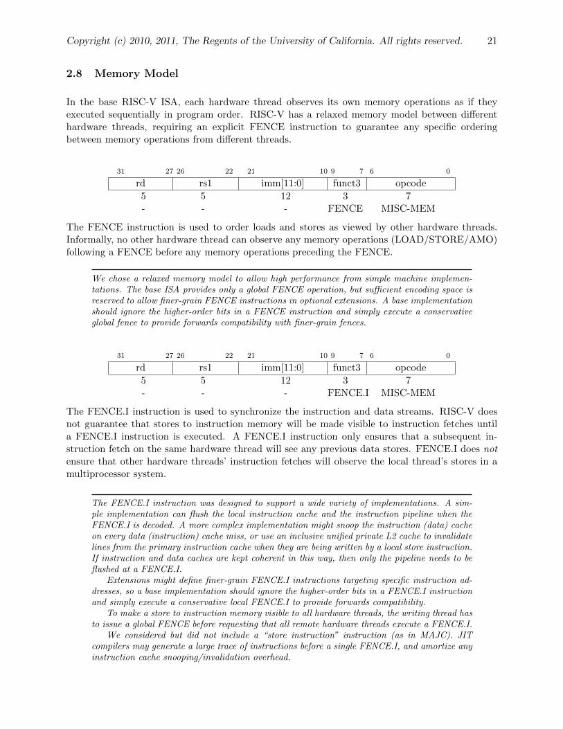
In the base RISC-V ISA, each hardware thread observes its own memory operations as if theyexecuted sequentially in program order. RISC-V has a relaxed memory model between differenthardware threads, requiring an explicit FENCE instruction to guarantee any specific orderingbetween memory operations from different threads.
31 27 26 22 21 10 9 7 6 0
rd rs1 imm[11:0] funct3 opcode
5 5 12 3 7- - - FENCE MISC-MEM
The FENCE instruction is used to order loads and stores as viewed by other hardware threads.Informally, no other hardware thread can observe any memory operations (LOAD/STORE/AMO)following a FENCE before any memory operations preceding the FENCE.
We chose a relaxed memory model to allow high performance from simple machine implemen-tations. The base ISA provides only a global FENCE operation, but sufficient encoding space isreserved to allow finer-grain FENCE instructions in optional extensions. A base implementationshould ignore the higher-order bits in a FENCE instruction and simply execute a conservativeglobal fence to provide forwards compatibility with finer-grain fences.
31 27 26 22 21 10 9 7 6 0
rd rs1 imm[11:0] funct3 opcode
5 5 12 3 7- - - FENCE.I MISC-MEM
The FENCE.I instruction is used to synchronize the instruction and data streams. RISC-V doesnot guarantee that stores to instruction memory will be made visible to instruction fetches untila FENCE.I instruction is executed. A FENCE.I instruction only ensures that a subsequent in-struction fetch on the same hardware thread will see any previous data stores. FENCE.I does notensure that other hardware threads’ instruction fetches will observe the local thread’s stores in amultiprocessor system.
The FENCE.I instruction was designed to support a wide variety of implementations. A sim-ple implementation can flush the local instruction cache and the instruction pipeline when theFENCE.I is decoded. A more complex implementation might snoop the instruction (data) cacheon every data (instruction) cache miss, or use an inclusive unified private L2 cache to invalidatelines from the primary instruction cache when they are being written by a local store instruction.If instruction and data caches are kept coherent in this way, then only the pipeline needs to beflushed at a FENCE.I.
Extensions might define finer-grain FENCE.I instructions targeting specific instruction ad-dresses, so a base implementation should ignore the higher-order bits in a FENCE.I instructionand simply execute a conservative local FENCE.I to provide forwards compatibility.
To make a store to instruction memory visible to all hardware threads, the writing thread hasto issue a global FENCE before requesting that all remote hardware threads execute a FENCE.I.
We considered but did not include a “store instruction” instruction (as in MAJC). JITcompilers may generate a large trace of instructions before a single FENCE.I, and amortize anyinstruction cache snooping/invalidation overhead.

22 RISC-V Specification
2.9 System Instructions
SYSTEM instructions are used to access system functionality that might require privileged accessand are encoded as an R-type instruction.
The SYSTEM instructions are defined to allow simpler implementations to always trap to asingle software exception handler. More sophisticated implementations might execute more ofeach system instruction in hardware.
SYSCALL and BREAK
31 27 26 22 21 17 16 7 6 0
rd rs1 rs2 funct10 opcode
5 5 5 10 70 0 0 SYSCALL SYSTEM0 0 0 BREAK SYSTEM
The SYSCALL instruction is used to make a request to an operating system environment. TheABI for the operating system will define how parameters for the OS request are passed, but usuallythese will be in defined locations in the fixed-point register file.
The BREAK instruction is used by debuggers to cause control to be transferred back to the de-bugging environment.

Copyright (c) 2010, 2011, The Regents of the University of California. All rights reserved. 23
Timers and Counters
31 27 26 22 21 17 16 7 6 0
rd rs1 rs2 funct10 opcode
5 5 5 10 7dest 0 0 RDCYCLE SYSTEMdest 0 0 RDTIME SYSTEMdest 0 0 RDINSTRET SYSTEM
The RDCYCLE instruction writes fixed-point register dest with a count of the number of clockcycles executed by the processor on which the hardware thread is running from an arbitrary starttime in the past. In RV32, this returns a 32-bit unsigned integer value that will wrap around whenthe count value overflows (modulo arithmetic). In RV64, this will return a 64-bit unsigned integervalue, which will never overflow. The rate at which the cycle counter advances will depend on theimplementation and operating environment. The software environment should provide a means todetermine the current rate (cycles/second) at which the cycle counter is incrementing.
The RDTIME instruction writes fixed-point register dest with an integer value corresponding tothe wall-clock real time that has passed from an arbitrary start time in the past. In RV32, thisreturns a 32-bit unsigned integer value that will wrap around when the time value overflows (moduloarithmetic). In RV64, this will return a 64-bit unsigned integer value, which should never overflow.The software environment should provide a means of determining the period of the real-time counter(seconds/tick). The period must be constant and should be no greater than 100 ns (at least 10 MHzrate). For RV32, the real-time clock period should be no shorter than 10 ns to allow periods ofup to 4 seconds to be measured simply. The real-time clocks of all hardware threads in a singleuser application should be synchronized to within one tick of the real-time clock. The environmentshould provide a means to determine the accuracy of the clock.
The RDINSTRET instruction writes fixed-point register dest with the number of instructions retiredby this hardware thread from some arbitrary start point in the past. In RV32, this returns anunsigned 32-bit integer value that will wrap around when the count overflows. In RV64, thisreturns an unsigned 64-bit integer value that will never overflow.
We mandate these basic counters be provided in all implementations as they are essential forbasic performance analysis, adaptive and dynamic optimization, and to allow an application towork with real-time streams. Additional counters should be provided to help diagnose performanceproblems and these should be made accessible from user-level application code with low overhead.
In some applications, it is important to be able to read multiple counters at the same instantin time. When run under a multitasking environment, a user thread can suffer a context switchwhile attempting to read the counters. One solution is for the user thread to read the real-timecounter before and after reading the other counters to determine if a context switch occured inthe middle of the sequence, in which case the reads can be retried. We considered adding outputlatches to allow a user thread to snapshot the counter values atomically, but this would increasethe size of the user context especially for implementations with a richer set of counters.
24 RISC-V Specification
3 Compressed Instruction Set Extension
The RISC-V compressed instruction set extension reduces static and dynamic code size by addingshort 16-bit instruction encodings for common integer operations. The compressed instructionencodings can be added to both RV64 and RV32, forming RVC64 and RVC32 respectively.
The RVC64 and RVC32 ISAs allow 16-bit instructions to be freely intermixed with the 32-bit baseinstructions, with the latter now able to start on any 16-bit boundary. All of the 16-bit instructionscan be expanded into one or more of the base RISC-V instructions.
The RVC ISAs are still under development, but we expect a 25–30% reduction in static anddynamic code size.

Copyright (c) 2010, 2011, The Regents of the University of California. All rights reserved. 25
31 27 26 22 21 17 16 15 14 12 11 10 9 8 7 6 0
jump target opcode J-typerd LUI-immediate opcode LUI-typerd rs1 imm[11:7] imm[6:0] funct3 opcode I-type
imm[11:7] rs1 rs2 imm[6:0] funct3 opcode B-typerd rs1 rs2 funct10 opcode R-typerd rs1 rs2 rs3 funct5 opcode R4-type
Unimplemented Instruction
Control Transfer Instructionsimm25 1100111 J imm25imm25 1101111 JAL imm25
imm12hi rs1 rs2 imm12lo 000 1100011 BEQ rs1,rs2,imm12imm12hi rs1 rs2 imm12lo 001 1100011 BNE rs1,rs2,imm12imm12hi rs1 rs2 imm12lo 100 1100011 BLT rs1,rs2,imm12imm12hi rs1 rs2 imm12lo 101 1100011 BGE rs1,rs2,imm12imm12hi rs1 rs2 imm12lo 110 1100011 BLTU rs1,rs2,imm12imm12hi rs1 rs2 imm12lo 111 1100011 BGEU rs1,rs2,imm12
rd rs1 imm12 000 1101011 JALR.C rd,rs1,imm12rd rs1 imm12 001 1101011 JALR.R rd,rs1,imm12rd rs1 imm12 010 1101011 JALR.J rd,rs1,imm12rd 00000 000000000000 100 1101011 RDNPC rd
Memory Instructionsrd rs1 imm12 000 0000011 LB rd,rs1,imm12rd rs1 imm12 001 0000011 LH rd,rs1,imm12rd rs1 imm12 010 0000011 LW rd,rs1,imm12rd rs1 imm12 011 0000011 LD rd,rs1,imm12rd rs1 imm12 100 0000011 LBU rd,rs1,imm12rd rs1 imm12 101 0000011 LHU rd,rs1,imm12rd rs1 imm12 110 0000011 LWU rd,rs1,imm12
imm12hi rs1 rs2 imm12lo 000 0100011 SB rs1,rs2,imm12imm12hi rs1 rs2 imm12lo 001 0100011 SH rs1,rs2,imm12imm12hi rs1 rs2 imm12lo 010 0100011 SW rs1,rs2,imm12imm12hi rs1 rs2 imm12lo 011 0100011 SD rs1,rs2,imm12
Atomic Memory Instructionsrd rs1 rs2 0000000 010 0101011 AMOADD.W rd,rs1,rs2rd rs1 rs2 0000001 010 0101011 AMOSWAP.W rd,rs1,rs2rd rs1 rs2 0000010 010 0101011 AMOAND.W rd,rs1,rs2rd rs1 rs2 0000011 010 0101011 AMOOR.W rd,rs1,rs2rd rs1 rs2 0000100 010 0101011 AMOMIN.W rd,rs1,rs2rd rs1 rs2 0000101 010 0101011 AMOMAX.W rd,rs1,rs2rd rs1 rs2 0000110 010 0101011 AMOMINU.W rd,rs1,rs2rd rs1 rs2 0000111 010 0101011 AMOMAXU.W rd,rs1,rs2rd rs1 rs2 0000000 011 0101011 AMOADD.D rd,rs1,rs2rd rs1 rs2 0000001 011 0101011 AMOSWAP.D rd,rs1,rs2rd rs1 rs2 0000010 011 0101011 AMOAND.D rd,rs1,rs2rd rs1 rs2 0000011 011 0101011 AMOOR.D rd,rs1,rs2rd rs1 rs2 0000100 011 0101011 AMOMIN.D rd,rs1,rs2rd rs1 rs2 0000101 011 0101011 AMOMAX.D rd,rs1,rs2rd rs1 rs2 0000110 011 0101011 AMOMINU.D rd,rs1,rs2rd rs1 rs2 0000111 011 0101011 AMOMAXU.D rd,rs1,rs2
26 RISC-V Specification
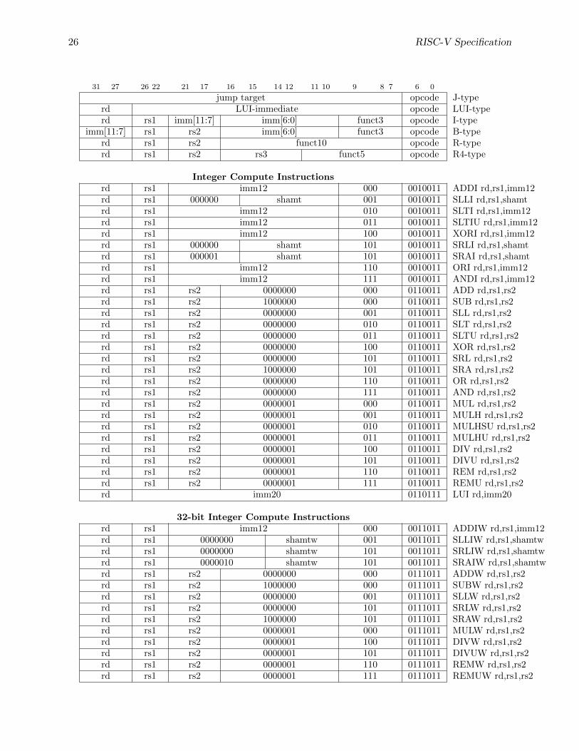
31 27 26 22 21 17 16 15 14 12 11 10 9 8 7 6 0
jump target opcode J-typerd LUI-immediate opcode LUI-typerd rs1 imm[11:7] imm[6:0] funct3 opcode I-type
imm[11:7] rs1 rs2 imm[6:0] funct3 opcode B-typerd rs1 rs2 funct10 opcode R-typerd rs1 rs2 rs3 funct5 opcode R4-type
Integer Compute Instructionsrd rs1 imm12 000 0010011 ADDI rd,rs1,imm12rd rs1 000000 shamt 001 0010011 SLLI rd,rs1,shamtrd rs1 imm12 010 0010011 SLTI rd,rs1,imm12rd rs1 imm12 011 0010011 SLTIU rd,rs1,imm12rd rs1 imm12 100 0010011 XORI rd,rs1,imm12rd rs1 000000 shamt 101 0010011 SRLI rd,rs1,shamtrd rs1 000001 shamt 101 0010011 SRAI rd,rs1,shamtrd rs1 imm12 110 0010011 ORI rd,rs1,imm12rd rs1 imm12 111 0010011 ANDI rd,rs1,imm12rd rs1 rs2 0000000 000 0110011 ADD rd,rs1,rs2rd rs1 rs2 1000000 000 0110011 SUB rd,rs1,rs2rd rs1 rs2 0000000 001 0110011 SLL rd,rs1,rs2rd rs1 rs2 0000000 010 0110011 SLT rd,rs1,rs2rd rs1 rs2 0000000 011 0110011 SLTU rd,rs1,rs2rd rs1 rs2 0000000 100 0110011 XOR rd,rs1,rs2rd rs1 rs2 0000000 101 0110011 SRL rd,rs1,rs2rd rs1 rs2 1000000 101 0110011 SRA rd,rs1,rs2rd rs1 rs2 0000000 110 0110011 OR rd,rs1,rs2rd rs1 rs2 0000000 111 0110011 AND rd,rs1,rs2rd rs1 rs2 0000001 000 0110011 MUL rd,rs1,rs2rd rs1 rs2 0000001 001 0110011 MULH rd,rs1,rs2rd rs1 rs2 0000001 010 0110011 MULHSU rd,rs1,rs2rd rs1 rs2 0000001 011 0110011 MULHU rd,rs1,rs2rd rs1 rs2 0000001 100 0110011 DIV rd,rs1,rs2rd rs1 rs2 0000001 101 0110011 DIVU rd,rs1,rs2rd rs1 rs2 0000001 110 0110011 REM rd,rs1,rs2rd rs1 rs2 0000001 111 0110011 REMU rd,rs1,rs2rd imm20 0110111 LUI rd,imm20
32-bit Integer Compute Instructionsrd rs1 imm12 000 0011011 ADDIW rd,rs1,imm12rd rs1 0000000 shamtw 001 0011011 SLLIW rd,rs1,shamtwrd rs1 0000000 shamtw 101 0011011 SRLIW rd,rs1,shamtwrd rs1 0000010 shamtw 101 0011011 SRAIW rd,rs1,shamtwrd rs1 rs2 0000000 000 0111011 ADDW rd,rs1,rs2rd rs1 rs2 1000000 000 0111011 SUBW rd,rs1,rs2rd rs1 rs2 0000000 001 0111011 SLLW rd,rs1,rs2rd rs1 rs2 0000000 101 0111011 SRLW rd,rs1,rs2rd rs1 rs2 1000000 101 0111011 SRAW rd,rs1,rs2rd rs1 rs2 0000001 000 0111011 MULW rd,rs1,rs2rd rs1 rs2 0000001 100 0111011 DIVW rd,rs1,rs2rd rs1 rs2 0000001 101 0111011 DIVUW rd,rs1,rs2rd rs1 rs2 0000001 110 0111011 REMW rd,rs1,rs2rd rs1 rs2 0000001 111 0111011 REMUW rd,rs1,rs2

Copyright (c) 2010, 2011, The Regents of the University of California. All rights reserved. 27
31 27 26 22 21 17 16 15 14 12 11 10 9 8 7 6 0
jump target opcode J-typerd LUI-immediate opcode LUI-typerd rs1 imm[11:7] imm[6:0] funct3 opcode I-type
imm[11:7] rs1 rs2 imm[6:0] funct3 opcode B-typerd rs1 rs2 funct10 opcode R-typerd rs1 rs2 rs3 funct5 opcode R4-type
Floating-Point Memory Instructionsrd rs1 imm12 010 0000111 FLW rd,rs1,imm12rd rs1 imm12 011 0000111 FLD rd,rs1,imm12
imm12hi rs1 rs2 imm12lo 010 0100111 FSW rs1,rs2,imm12imm12hi rs1 rs2 imm12lo 011 0100111 FSD rs1,rs2,imm12
Floating-Point Compute Instructionsrd rs1 rs2 00000 rm 00 1010011 FADD.S rd,rs1,rs2[,rm]rd rs1 rs2 00001 rm 00 1010011 FSUB.S rd,rs1,rs2[,rm]rd rs1 rs2 00010 rm 00 1010011 FMUL.S rd,rs1,rs2[,rm]rd rs1 rs2 00011 rm 00 1010011 FDIV.S rd,rs1,rs2[,rm]rd rs1 00000 00100 rm 00 1010011 FSQRT.S rd,rs1[,rm]rd rs1 rs2 11000 000 00 1010011 FMIN.S rd,rs1,rs2rd rs1 rs2 11001 000 00 1010011 FMAX.S rd,rs1,rs2rd rs1 rs2 00000 rm 01 1010011 FADD.D rd,rs1,rs2[,rm]rd rs1 rs2 00001 rm 01 1010011 FSUB.D rd,rs1,rs2[,rm]rd rs1 rs2 00010 rm 01 1010011 FMUL.D rd,rs1,rs2[,rm]rd rs1 rs2 00011 rm 01 1010011 FDIV.D rd,rs1,rs2[,rm]rd rs1 00000 00100 rm 01 1010011 FSQRT.D rd,rs1[,rm]rd rs1 rs2 11000 000 01 1010011 FMIN.D rd,rs1,rs2rd rs1 rs2 11001 000 01 1010011 FMAX.D rd,rs1,rs2rd rs1 rs2 rs3 rm 00 1000011 FMADD.S rd,rs1,rs2,rs3[,rm]rd rs1 rs2 rs3 rm 00 1000111 FMSUB.S rd,rs1,rs2,rs3[,rm]rd rs1 rs2 rs3 rm 00 1001011 FNMSUB.S rd,rs1,rs2,rs3[,rm]rd rs1 rs2 rs3 rm 00 1001111 FNMADD.S rd,rs1,rs2,rs3[,rm]rd rs1 rs2 rs3 rm 01 1000011 FMADD.D rd,rs1,rs2,rs3[,rm]rd rs1 rs2 rs3 rm 01 1000111 FMSUB.D rd,rs1,rs2,rs3[,rm]rd rs1 rs2 rs3 rm 01 1001011 FNMSUB.D rd,rs1,rs2,rs3[,rm]rd rs1 rs2 rs3 rm 01 1001111 FNMADD.D rd,rs1,rs2,rs3[,rm]

28 RISC-V Specification
31 27 26 22 21 17 16 15 14 12 11 10 9 8 7 6 0
jump target opcode J-typerd LUI-immediate opcode LUI-typerd rs1 imm[11:7] imm[6:0] funct3 opcode I-type
imm[11:7] rs1 rs2 imm[6:0] funct3 opcode B-typerd rs1 rs2 funct10 opcode R-typerd rs1 rs2 rs3 funct5 opcode R4-type
Floating-Point Move & Conversion Instructionsrd rs1 rs2 00101 000 00 1010011 FSGNJ.S rd,rs1,rs2rd rs1 rs2 00110 000 00 1010011 FSGNJN.S rd,rs1,rs2rd rs1 rs2 00111 000 00 1010011 FSGNJX.S rd,rs1,rs2rd rs1 rs2 00101 000 01 1010011 FSGNJ.D rd,rs1,rs2rd rs1 rs2 00110 000 01 1010011 FSGNJN.D rd,rs1,rs2rd rs1 rs2 00111 000 01 1010011 FSGNJX.D rd,rs1,rs2rd rs1 00000 10001 rm 00 1010011 FCVT.S.D rd,rs1[,rm]rd rs1 00000 10000 rm 01 1010011 FCVT.D.S rd,rs1[,rm]
Integer to Floating-Point Move & Conversion Instructionsrd rs1 00000 01100 rm 00 1010011 FCVT.S.L rd,rs1[,rm]rd rs1 00000 01101 rm 00 1010011 FCVT.S.LU rd,rs1[,rm]rd rs1 00000 01110 rm 00 1010011 FCVT.S.W rd,rs1[,rm]rd rs1 00000 01111 rm 00 1010011 FCVT.S.WU rd,rs1[,rm]rd rs1 00000 01100 rm 01 1010011 FCVT.D.L rd,rs1[,rm]rd rs1 00000 01101 rm 01 1010011 FCVT.D.LU rd,rs1[,rm]rd rs1 00000 01110 rm 01 1010011 FCVT.D.W rd,rs1[,rm]rd rs1 00000 01111 rm 01 1010011 FCVT.D.WU rd,rs1[,rm]rd rs1 00000 11110 000 00 1010011 MXTF.S rd,rs1rd rs1 00000 11110 000 01 1010011 MXTF.D rd,rs1rd rs1 00000 11111 000 00 1010011 MTFSR rd,rs1
Floating-Point to Integer Move & Conversion Instructionsrd rs1 00000 01000 rm 00 1010011 FCVT.L.S rd,rs1[,rm]rd rs1 00000 01001 rm 00 1010011 FCVT.LU.S rd,rs1[,rm]rd rs1 00000 01010 rm 00 1010011 FCVT.W.S rd,rs1[,rm]rd rs1 00000 01011 rm 00 1010011 FCVT.WU.S rd,rs1[,rm]rd rs1 00000 01000 rm 01 1010011 FCVT.L.D rd,rs1[,rm]rd rs1 00000 01001 rm 01 1010011 FCVT.LU.D rd,rs1[,rm]rd rs1 00000 01010 rm 01 1010011 FCVT.W.D rd,rs1[,rm]rd rs1 00000 01011 rm 01 1010011 FCVT.WU.D rd,rs1[,rm]rd 00000 rs2 11100 000 00 1010011 MFTX.S rd,rs2rd 00000 rs2 11100 000 01 1010011 MFTX.D rd,rs2rd 00000 00000 11101 000 00 1010011 MFFSR rd

Copyright (c) 2010, 2011, The Regents of the University of California. All rights reserved. 29
31 27 26 22 21 17 16 15 14 12 11 10 9 8 7 6 0
jump target opcode J-typerd LUI-immediate opcode LUI-typerd rs1 imm[11:7] imm[6:0] funct3 opcode I-type
imm[11:7] rs1 rs2 imm[6:0] funct3 opcode B-typerd rs1 rs2 funct10 opcode R-typerd rs1 rs2 rs3 funct5 opcode R4-type
Floating-Point Compare Instructionsrd rs1 rs2 10101 000 00 1010011 FEQ.S rd,rs1,rs2rd rs1 rs2 10110 000 00 1010011 FLT.S rd,rs1,rs2rd rs1 rs2 10111 000 00 1010011 FLE.S rd,rs1,rs2rd rs1 rs2 10101 000 01 1010011 FEQ.D rd,rs1,rs2rd rs1 rs2 10110 000 01 1010011 FLT.D rd,rs1,rs2rd rs1 rs2 10111 000 01 1010011 FLE.D rd,rs1,rs2
Miscellaneous Memory Instructionsrd rs1 imm12 001 0101111 FENCE.I rd,rs1,imm12rd rs1 imm12 010 0101111 FENCE rd,rs1,imm12
System Instructions00000 00000 00000 0000000 000 1110111 SYSCALL00000 00000 00000 0000000 001 1110111 BREAK
rd 00000 00000 0000000 100 1110111 RDCYCLE rdrd 00000 00000 0000001 100 1110111 RDTIME rdrd 00000 00000 0000010 100 1110111 RDINSTRET rd
Table 6: Instruction listing for RISC-V

30 RISC-V Specification
4 Floating-Point Extensions
This section describes the optional 128-bit binary floating-point instructions, and how we wouldintend to support the decimal floating-point arithmetic defined in the IEEE 754-2008 standard.
4.1 Quad-Precision Binary Floating-Point Extension
The 128-bit or quad-precision binary floating-point extensions are built upon the base floating-pointinstructions, and are only available as an extension to RV[C]64. The floating-point registers arenow extended to hold either a single, double, or quad-precision floating-point value.
A new supported format is added to the format field of most instructions, as shown in Table 7.
fmt field Mnemonic Meaning00 S 32-bit single-precision01 D 64-bit double-precision10 - reserved11 Q 128-bit quad-precisionn
Table 7: Format field encoding.
The following instructions support the quad-precision format: FADD/FSUB, FMUL/FDIV, FSQRT,F[N]MADD/F[N]MSUB, FCVT.fmt.W[U], FCVT.W[U].fmt, FCVT.fmt.L[U], FCVT.L[U].fmt, FS-GNJ[N], FSGNX, and FEQ/FLT/FLE.
New floating-point to floating-point conversion instructions FCVT.S.Q, FCVT.Q.S, FCVT.D.Q,FCVT.Q.D are added.
MFTX.Q and MXTF.Q instructions are not provided, so quad-precision bit patterns must be movedto the integer registers via memory.
New 128-bit variants of LOAD-FP and STORE-FP instructions are added, encoded with a newvalue for the width field.
4.2 Decimal Floating-Point Extension
The existing floating-point registers can be used to hold 64-bit and 128-bit decimal floating-pointvalues, with the existing floating-point load and store instructions used to move values to and frommemory.
Due to the large opcode space required by the fused multiply-add instructions, the decimal floating-point instruction extension requires a 48-bit instruction encoding.
Copyright (c) 2010, 2011, The Regents of the University of California. All rights reserved. 31
5 Packed-SIMD Extensions
In this section, we outline how a packed-SIMD extension could be added to RISC-V (any of RV[C]64or RV[C]32).
A packed-SIMD extension will have some fixed register width of 64 bits, 128 bits, or larger. Theseregisters will be overlaid on the RISC-V floating-point registers. Each register can be treatedas N×64-bit, 2N×32-bit, 4N×16-bit, or 8N×8-bit packed variables, where N is 1 for the base64-bit floating-point ISA but can be extended up to N = 64 (4096-bit registers). Packed-SIMDinstructions operate on these packed values in FP registers.
The existing floating-point load and store instructions can be used to load and store various-sizedwords from memory. The base ISA supports 32-bit and 64-bit loads and stores, but the LOAD-FPand STORE-FP instruction encodings allow up to 8 different widths to be encoded (32, 64, 128,256, 512, 1024, 2048, 4096). When used with packed-SIMD operations, it is desirable to supportnon-naturally aligned loads and stores in hardware.
Simple packed-SIMD extensions might fit in unused 32-bit instruction opcodes, but more extensivepacked-SIMD extensions will likely require a 48-bit instruction encoding.
It is natural to use the floating-point registers for packed-SIMD values rather than the integerregisters (PA-RISC and Alpha packed-SIMD extensions) as this frees the integer registers forcontrol and address values and leads naturally to a decoupled integer/floating-point unit hardwaredesign. The floating-point load and store instruction encodings also have space to handle widerpacked-SIMD registers.
Reusing the floating-point registers for packed-SIMD values does make it more difficult touse a recoded internal format for floating-point values.
32 RISC-V Specification
6 History and Acknowledgements
The RISC-V ISA and instruction set manual builds up several earlier projects. Several aspects ofthe supervisor-level machine and the overall format of the manual date back to the T0 (Torrent-0)vector microprocessor project at UC Berkeley and ICSI, begun in 1992. T0 was a vector processorbased on the MIPS-II ISA, with Krste Asanovic as main architect and RTL designer, and BrianKingsbury and Bertrand Irrisou as principal VLSI implementers. David Johnson at ICSI was amajor contributor to the T0 ISA design, particularly supervisor mode, and to the manual text.John Hauser also provided considerable feedback on the T0 ISA design.
The Scale (Software-Controlled Architecture for Low Energy) project at MIT, begun in 2000, builtupon the T0 project infrastructure, refined the supervisor-level interface, and moved away from theMIPS scalar ISA by dropping the branch delay slot. Ronny Krashinsky and Christopher Battenwere the principal architects of the Scale Vector-Thread processor at MIT, while Mark Hamptonported the GCC-based compiler infrastructure and tools for Scale.
A lightly edited version of the T0 MIPS scalar processor specification (MIPS-6371) was used inteaching a new version of the MIT 6.371 Introduction to VLSI Systems class in the Fall 2002semester, with Chris Terman and Krste Asanovic as lecturers. Chris Terman contributed mostof the lab material for the class (there was no TA!). The 6.371 class evolved into the trial 6.884Complex Digital Design class at MIT, taught by Arvind and Krste Asanovic in Spring 2005, whichbecame a regular Spring class 6.375. A reduced version of the Scale MIPS-based scalar ISA, namedSMIPS, was used in 6.884/6.375. Christopher Batten was the TA for the early offerings of theseclasses and developed a considerable amount of documentation and lab material based around theSMIPS ISA. This same SMIPS lab material was adapted and enhanced by TA Yunsup Lee forthe UC Berkeley Fall 2009 CS250 VLSI Systems Design class taught by John Wawrzynek, KrsteAsanovic, and John Lazzaro.
The Maven (Malleable Array of Vector-thread ENgines) project was a second-generation vector-thread architecture, whose design was led by Christopher Batten while an Exchange Scholar atUC Berkeley starting in summer 2007. Hidetaka Aoki, a visiting industrial fellow from Hitachigave considerable feedback on the early Maven ISA and microarchitecture design. The Maveninfrastructure was based on the Scale infrastructure but the Maven ISA moved further away fromthe MIPS ISA variant defined in Scale, with a unified floating-point and integer register file. Mavenwas designed to support experimentation with alternative data-parallel accelerators. Yunsup Leewas the main implementor of the various Maven vector units, while Rimas Avizienis was the mainimplementor of the various Maven scalar units. Christopher Batten and Yunsup Lee ported GCCto work with the new Maven ISA. Christopher Celio provided the initial definition of a traditionalvector instruction set (“Flood”) variant of Maven.
Based on experience with all these previous projects, the RISC-V ISA definition was begun inSummer 2010. An initial version of the RISC-V 32-bit instruction subset was used in the UCBerkeley Fall 2010 CS250 VLSI Systems Design class. RISC-V is a clean break from the earlierMIPS-inspired designs. John Hauser contributed to the floating-point ISA definition.