
RIOduino - REV Robotics popular application for Arduino-compatible boards like the RIOduino is to...
12
REV-11-1104-UM-00 Copyright © 2014 REV Robotics, LLC 1 RIOduino USER'S MANUAL
Transcript of RIOduino - REV Robotics popular application for Arduino-compatible boards like the RIOduino is to...
REV-11-1104-UM-00 Copyright © 2014 REV Robotics, LLC 1
fg
RIOduino USER'S MANUAL

REV-11-1104-UM-00 Copyright © 2014 REV Robotics, LLC 2
TABLE OF CONTENTS
1 RIOduino OVERVIEW .............................................................................................................................................................. 3
1.1 FEATURES ..................................................................................................................................................................... 4
1.2 KIT CONTENTS .............................................................................................................................................................. 4
2 FEATURE DESCRIPTION ........................................................................................................................................................ 5
2.1 ARDUINO COMPATIBILITY ........................................................................................................................................... 5
2.2 POWER OPTIONS .......................................................................................................................................................... 5
2.2.1 VIN SOURCE REQUIREMENTS .................................................................................................................................. 5
2.2.2 POWER SOURCE SELECTION ................................................................................................................................... 5
2.2.3 POWER SUPPLY CAPABILITIES ............................................................................................................................... 6
2.3 MXP SIGNALS................................................................................................................................................................ 6
2.3.1 SHARED I2C................................................................................................................................................................ 7
2.3.2 SHARED UART ........................................................................................................................................................... 7
2.4 WS281x RGB LED STRIP CONNECTIONS .................................................................................................................... 7
2.5 MOUNTING HOLES ........................................................................................................................................................ 8
APPENDIX A SCHEMATIC ....................................................................................................................................................... 9
APPENDIX B DRAWING......................................................................................................................................................... 10
APPENDIX C BILL OF MATERIALS ....................................................................................................................................... 11
LIST OF FIGURES Figure 1-1 RIOduino ....................................................................................................................................................................... 3
Figure 2-1 MXP Signal Access ...................................................................................................................................................... 6
Figure 2-2 Connecting WS281x LED Strip to RIOduino ............................................................................................................... 8
LIST OF TABLES
Table 2-1 VIN Voltage Requirements ............................................................................................................................................. 5
Table 2-2 Automatic Power Selection Truth Table ...................................................................................................................... 5
Table 2-3 Maximum Supply Current ............................................................................................................................................. 6
Table 2-4 Shared I2C Signals ......................................................................................................................................................... 7
Table 2-5 Shared UART Signals .................................................................................................................................................... 7
Table 2-6 Recommended Mounting Screw Sizes ........................................................................................................................ 8
REV-11-1104-UM-00 Copyright © 2014 REV Robotics, LLC 3
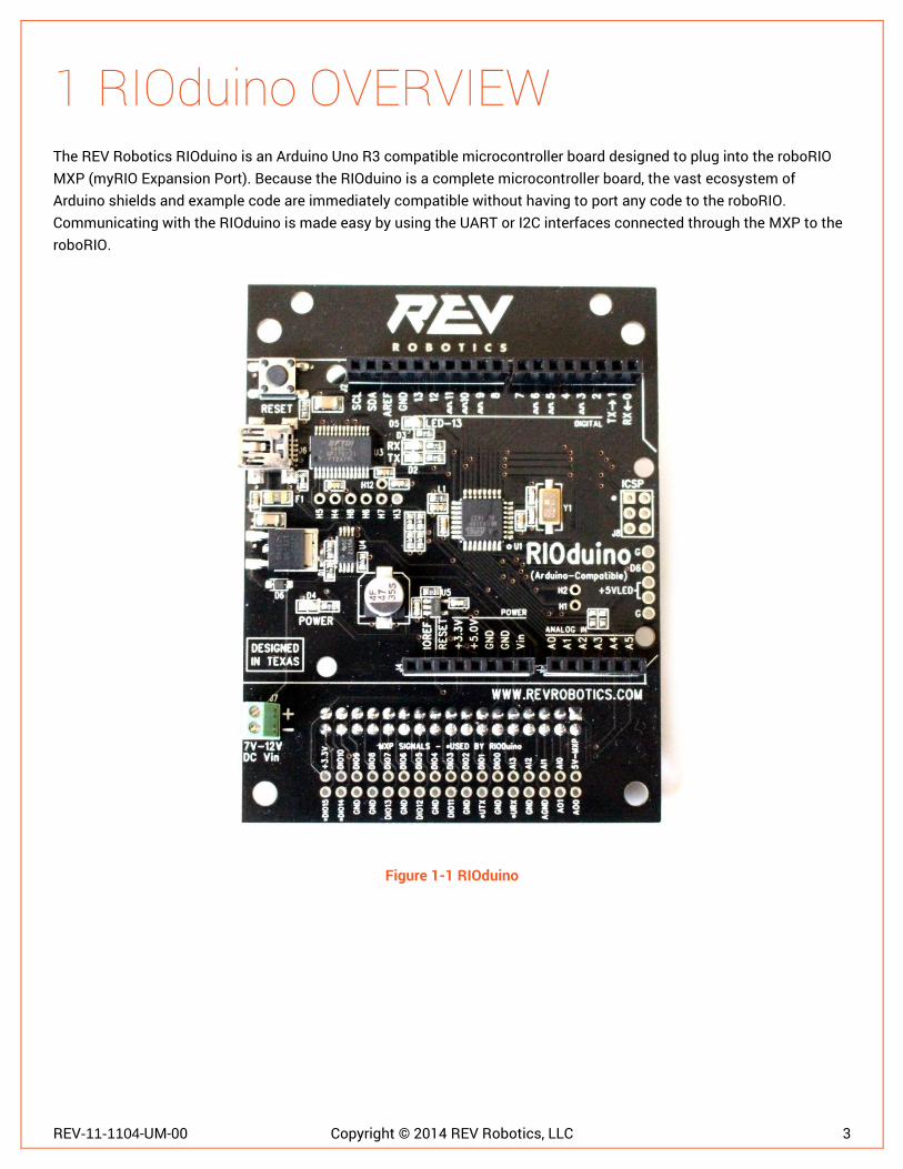
1 RIOduino OVERVIEW The REV Robotics RIOduino is an Arduino Uno R3 compatible microcontroller board designed to plug into the roboRIO MXP (myRIO Expansion Port). Because the RIOduino is a complete microcontroller board, the vast ecosystem of Arduino shields and example code are immediately compatible without having to port any code to the roboRIO. Communicating with the RIOduino is made easy by using the UART or I2C interfaces connected through the MXP to the roboRIO.
Figure 1-1 RIOduino
REV-11-1104-UM-00 Copyright © 2014 REV Robotics, LLC 4
1.1 FEATURES
The REV Robotics RIOduino includes the following features:
Arduino Uno R3 compatible microcontroller board o Compatible with virtually all Arduino Uno R3 footprint shields
3 auto-selecting power options o VIN terminal - 12.0 V (from PDP, VRM, etc.) o MXP connector - 5.0 V o USB connector - 5.0 V
Serial connections between RIOduino and roboRIO o UART (TTL levels) o I2C
All MXP signals are passed through to 0.1" header positions o 4 MXP signals are connected to the RIOduino
UART.RX UART.TX DIO14/I2CSCL DIO15/I2CSDA
o Remaining signals are pass-through only o Allows for stacking of MXP boards with provided connector
Connections for WS281x LED strips o Power externally provided
Mounting holes o 2 holes for roboRIO mounting, 4-40 x 3/16" screws o 4 Arduino footprint mounting holes, #4 sized screws o 4 holes for additional mounting options, #6 sized screws
1.2 KIT CONTENTS
The REV Robotics RIOduino comes with the following:
RIOduino USB A to mini B cable Female MXP connector 2 roboRIO mounting screws, 4-40 x 3/16"
REV-11-1104-UM-00 Copyright © 2014 REV Robotics, LLC 5
2 FEATURE DESCRIPTION The REV Robotics RIOduino is designed to seamlessly integrate the vast Arduino ecosystem into the FIRST Robotics Competition control system. This section describes these RIOduino features in detail.
2.1 ARDUINO COMPATIBILITY
The RIOduino is compatible with the latest Arduino UNO R3 footprint. It features an Atmel ATmega328 8-bit microcontroller and can be programmed over USB using the Arduino integrated development environment (IDE). Each board comes with the Arduino bootloader preprogrammed on the ATmega328. Please see the RIOduino Getting Started Guide at www.revrobotics.com/product/rioduino for instructions on how to program the RIOduino for the first time.
For more information on the Arduino UNO R3, the Arduino IDE, compatible shields, and access to the vast Arduino community, please visit arduino.cc.
2.2 POWER OPTIONS
The RIOduino can be powered from one of three power sources: the VIN terminal, MXP connector, or USB connector. It can also supply power to connected circuitry and shields.
2.2.1 V I N SOURCE REQUIREMENTS When powering the RIOduino from either the VIN pin (J4.8) or the VIN screw terminal (J7) please ensure the voltage meets the input requirements outlined in Table 2-1.
Table 2-1 VIN Voltage Requirements
MIN TYP MAX VIN 7.0 V - 12.0 V
If VIN drops below 7.0 V the on-board regulator is at risk of browning out and resetting the RIOduino. If VIN is higher than 12.0 V, the on-board regulator can overheat and be damaged.
2.2.2 POWER SOURCE SELECTION Circuitry on the RIOduino automatically selects the best source for power with the priority given first to the VIN terminal, then the MXP connector, and then the USB connector. Table 2-2 shows the truth table behind the power source selection.
Table 2-2 Automatic Power Selection Truth Table
VIN > 2.7 V1 VMXP > VUSB Selected Source
No No USB Yes MXP
Yes X VIN 1. Note that VIN must be 7.0 V - 12.0 V for the RIOduino to
operate properly, however a VIN greater than 2.7 V will force the selection of VIN as the input source. Please see 2.2.1 VIN SOURCE REQUIREMENTS for more information.

REV-11-1104-UM-00 Copyright © 2014 REV Robotics, LLC 6
The power selection scheme makes it possible to program and debug over USB without removing the RIOduino from the system.
2.2.3 POWER SUPPLY CAPABILITIES The RIOduino can supply both 5.0V and 3.3V to connected circuitry and shields. Table 2-3 lists the maximum current capabilities for each supply depending on the RIOduino power source.
Table 2-3 Maximum Supply Current
Power Source USB MXP VIN 3.3 V Rail - IMAX 50 mA 1.5 A2 50 mA 5.0 V Rail - IMAX
1 500 mA 1.0 A 1.0 A
1. These are the absolute maximums for the 5.0 V rail current. The actual available current will less and will depend on the 3.3 V rail current and any on-board current draw (including the microcontroller).
2. This is the maximum output current for the roboRIO 3.3 V rail. The actual available current depends on any other devices connected to the roboRIO 3.3V rail.
When powered by the MXP connector, the on-board 3.3 V regulator (U5) is put into a shutdown mode and 3.3 V power is provided by the roboRIO. Pin 8 on the MXP connector (J1) is connected to the pin (U5.3) and is tied to ground once it is connected to the matching pin 8 on the roboRIO MXP.
2.3 MXP SIGNALS
All MXP signals are routed to 2x17 0.1" spaced grid of holes along the bottom edge of the board, see Figure 2-1.
Figure 2-1 MXP Signal Access
The included female MXP connector can be soldered to these holes and used in tandem with the REV Robotics MXP Extension Cable (REV-1-1118) to stack an additional MXP board like the REV More Board (REV-11-1100).
Both I2C and UART are connected between the roboRIO and the RIOduino providing the means to communicate between the two.

REV-11-1104-UM-00 Copyright © 2014 REV Robotics, LLC 7
2.3.1 SHARED I2C Table 2-4 shows which signals are shared for I2C.
Table 2-4 Shared I2C Signals
RIOduino Signal RIOduino Shield Pin MXP Pin MXP Signal AD4/SDA J3.5 J1.34 DIO15/I2CSDA AD5/SCL J3.6 J1.32 DIO14/I2CSCL
As with any I2C bus, pull-up resistors are required for both SCL and SDA. To keep AD4 and AD5 free for analog use, the RIOduino has two unpopulated positions (R12, R13) for 2.2 kΩ 0603 surface mount resistors. When used with the roboRIO, these external resistors are not needed because the roboRIO has internal pull-up resistors. For other applications, these resistors can be added. Please see APPENDIX A SCHEMATIC and APPENDIX B DRAWING for the schematic and component placement drawing.
2.3.2 SHARED UART Table 2-5 shows which signals are shared for UART.
Table 2-5 Shared UART Signals
RIOduino Signal RIOduino Shield Pin MXP Pin MXP Signal IO0/RX J5.1 J1.14 UART.TX IO1/TX J5.2 J1.10 UART.RX
CAUTION The UART signals are at TTL levels. Do not connect directly to a RS-232 serial port without an RS-232 to TTL converter.
The UART on the ATmega328 is connected to both the MXP connector and the on-board USB to Serial converter through 1 kΩ resistors. These resistors prevent either the roboRIO or the USB to Serial converter from forcibly driving the bus when another UART device is connected through the shield headers.
2.4 WS281x RGB LED STRIP CONNECTIONS
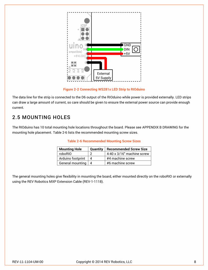
A popular application for Arduino-compatible boards like the RIOduino is to control addressable RGB LED strips like the WS2811 and WS2812 based strips. The RIOduino includes five plated-through holes that make it easy to connect one of these strips and its external power source. Figure 2-2 shows how to wire a WS281x LED strip with an external 5V supply.
REV-11-1104-UM-00 Copyright © 2014 REV Robotics, LLC 8
Figure 2-2 Connecting WS281x LED Strip to RIOduino
The data line for the strip is connected to the D6 output of the RIOduino while power is provided externally. LED strips can draw a large amount of current, so care should be given to ensure the external power source can provide enough current.
2.5 MOUNTING HOLES
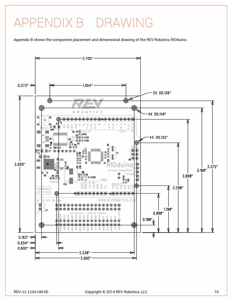
The RIOduino has 10 total mounting hole locations throughout the board. Please see APPENDIX B DRAWING for the mounting hole placement. Table 2-6 lists the recommended mounting screw sizes.
Table 2-6 Recommended Mounting Screw Sizes
Mounting Hole Quantity Recommended Screw Size roboRIO 2 4-40 x 3/16" machine screw Arduino footprint 4 #4 machine screw General mounting 4 #6 machine screw
The general mounting holes give flexibility in mounting the board, either mounted directly on the roboRIO or externally using the REV Robotics MXP Extension Cable (REV-1-1118).
REV-11-1104-UM-00 Copyright © 2014 REV Robotics, LLC 9
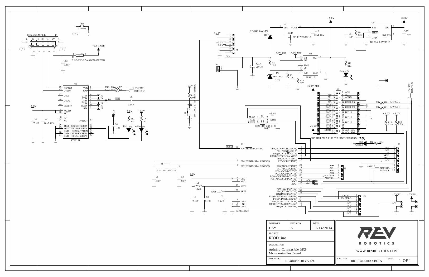
APPENDIX A SCHEMATIC Appendix A shows the schematic for the REV Robotics RIOduino.
RR-RIODUINO-BD-A
Microcontroller Board
Arduino Compatible MXP
WWW.REVROBOTICS.COM
PROJECT
DESCRIPTION
FILENAME
DESIGNER
REVISION
DATE
PART NO.
SHEET
1
1
OF
RIOduino-RevA.sch
11/14/2014
A
RIODuino
DAY
29
PC6(RESET/PCINT14)
7
PB6(PCINT6/XTAL1/TOSC1)
8
PB7(PCINT7/XTAL2/TOSC2)
18
AVCC
4
VCC
6
VCC
20
AREF
3
GND
5
GND
21
GND
12
PB0(PCINT0/CLKO/ICP1)
13
PB1(PCINT1/OC1A)
14
PB2(PCINT2/SS/OC1B)
15
PB3(PCINT3/OC2A/MOSI)
16
PB4(PCINT4/MISO)
17
PB5(SCK/PCINT5)
23
PC0(ADC0/PCINT8)
24
PC1(ADC1/PCINT9)
25
PC2(ADC2/PCINT10)
26
PC3(ADC3/PCINT11)
27
PC4(ADC4/SDA/PCINT12)
28
PC5(ADC5/SCL/PCINT13)
19
ADC6
22
ADC7
30
PD0(RXD/PCINT16)
31
PD1(TXD/PCINT17)
32
PD2(INT0/PCINT18)
1
PD3(PCINT19/OC2B/INT1)
2
PD4(PCINT20/XCK/T0)
9
PD5(PCINT21/OC0B/T1)
10
PD6(PCINT22/OC0A/AIN0)
11
PD7(PCINT23/AIN1)
U1
ATMEGA328
16
USBDM
15
USBDP
27
OSCI
28
OSCO
19
RESET#
20
VCC
4
VCCIO
17
3V3OUT
26
TEST
25
AGND
7
GND
18
GND
21
GND
1
TXD
5
RXD
11
CTS#
3
RTS#
2
DTR#
9
DSR#
10
DCD#
6
RI#
8
NC
24
NC
23
CBUS0/TXLED#
22
CBUS1/RXLED#
13
CBUS2/TXDEN
14
CBUS3/PWREN#
12
CBUS4/SLEEP#
U3
FT232RL
1
3
5
7
9
11
13
15
17
19
21
23
25
27
29
31
33
2
4
6
8
10
12
14
16
18
20
22
24
26
28
30
32
34
J1
CON-HDR-2X17-0100-THS-DBCOGJ254DS34
1
2
3
4
5
6
7
8
9
10
J2
1
2
3
4
5
6
J3
1
2
3
4
5
6
7
8
J4
1
2
3
4
5
6
7
8
J5
L1
10uH
C1
0.1uF
C2
0.1uF
C3
0.1uF
Y1
ECS-160-20-3X-TR
C4
20pF
C5
20pF
R1
10K
C6
0.1uF
H1
H2
3
VIN
4
VOUT
1
GND
U2
AP1117ID50G-13
1
STAT
2
D0
3
D1
4
ILIM
8
IN1
7
OUT
6
IN2
5
GND
U4
TPS2115
D1
MM5Z4V7
4.7V
R4
3K
R3
10K
1
2
F1
FUSE-PTC-0.5A-0ZCA0050FF2G
1
5V
2
D-
3
D+
4
ID
5
G
6
7
9
8
J6
CON-USB-MINI-B
C7
10uF 16V
C8
1uF
D2
Yellow
R2
1K
D3
Red
R5
1K
R6
0 OHMS
H3
H4
R7
1K
R8
1K
H5
H6
H7
H8
C9
0.1uF
H12
1
VIN
2
GND
3
SHDN
5
VOUT
4
BYPASS
U5
TC1014-3.3VCT713
C10
1uF
C11
1uF
C12
10uF 16V
R9
10K
R10
1K
R11
1K
R12
2.2K
R13
2.2K
C13
0.1uF
+
C14
47uF
D4
Green
R14
1K
D5
Green
R15
1K
1
2
3
4
5
6
J8
CON-HDR-2X3-0100
OMIT
R16
400
D6
SD101AW-TP
1
3
2
4
S1
SW
-TACT-P
TS645SM
43SM
TR92
1
2
J7
IO8
IO9
SS
MOSI
MISO
SCK
AD0
AD1
AD2
AD3
AD4/SDA
AD5/SCL
AREF
+5.0V
+5.0V
RESET
AREF
AD6
AD7
+5.0V
+3.3V
+5.0V
+5.0V
VIN
+5.0V_MXP
+5.0V_USB
DTR
+5.0V
+5.0V
+5.0V_USB
IO0/RX-I
IO1/TX-O
TXD
RXD
+5.0V
+5.0V_MXP
+3.3V
+3.3V
AD5/SCL
AD4/SDA
IO0/RX-I
IO1/TX-O
IO2
IO3
IO4
IO5
IO6
IO7
UART.RX
UART.TX
IO1/TX-O
IO0/RX-I
+5.0V
+5.0V
AO0
AO1
AGND
DIO11
DIO12
DIO13
AD5/SCL
AD4/SDA
AI0
AI1
AI2
AI3
DIO0
DIO1
DIO2
DIO3
DIO4
DIO5
DIO6
DIO7
DIO8
DIO9
DIO10
+5.0V
MISO
SCK
MOSI
RESET
IO1/T
X-O
IO0/R
X-I
+5VLED
IO6
+5VLED
REV-11-1104-UM-00 Copyright © 2014 REV Robotics, LLC 10
APPENDIX B DRAWING Appendix B shows the component placement and dimensional drawing of the REV Robotics RIOduino.

REV-11-1104-UM-00 Copyright © 2014 REV Robotics, LLC 11
APPENDIX C BILL OF MATERIALS Appendix C shows the bill of materials for the REV Robotics RIOduino.
RIOduino Bill of Materials
Item Ref Qty Description Mfg Part Number
1 C1-3 C6 C9 C13 6 CAP CER 0.1UF 50V Y5V 0603 Samsung CL10F104ZB8NNNC
2 C14 1 CAP ALUM 47UF 25V 20% SMD Nichicon UWT1E470MCL6GS
3 C4-5 2 CAP CER 20PF 50V 5% NP0 0603 Samsung CL10C200JB8NCNC
4 C7 C12 2 CAP CER 10UF 16V Y5V 1206 Samsung CL31F106ZOHNNNE
5 C8 C10-11 3 CAP CER 1UF 25V 10% X5R 0603 Murata GRM188R61E105KA12D
6 D1 1 DIODE ZENER 4.7V 200MW SOD523F Fairchild MM5Z4V7
7 D2 1 LED CHIPLED 588NM YLW 0805 SMD OSRAM LY R976-PS-36
8 D3 1 LED CHIPLED 645NM RED DIFF 0805 OSRAM LH R974-LP-1
9 D4-5 2 LED CHIPLED 570NM GREEN 0805 SMD OSRAM LG R971-KN-1
10 D6 1 DIODE SCHOTTKY 40V SOD323 MCC SD101CWS-TP
11 F1 1 PTC RESTTBLE 0.50A 8V CHIP 1206 Bel 0ZCA0050FF2G
12 J1 1 2x17-Pin Female Box Header, 0.1", Keyed Xiamen DBCOGJ254DS34
13 J2 1 CONN FEMALE 10POS .1" SMD TIN Sullins PPTC101LFBN-RC
14 J3 1 CONN FEMALE 6POS .1" SMD TIN Sullins PPTC061LFBN-RC
15 J4-5 2 CONN FEMALE 8POS .1" SMD TIN Sullins PPTC081LFBN-RC
16 J6 1 CONN MINI USB RCPT RA TYPE B SMD EDAC 690-005-299-043
17 J7 1 CONN TERM BLOCK 2.54MM 2POS PCB On Shore OSTVN02A150
18 L1 1 INDUCTOR MULTILAYER 10000NH 0603 Abracon AIML-0603-100K-T
19 R1 R3 R9 3 RES 10K OHM 1/10W 5% 0603 SMD Rohm MCR03ERTJ103
21 R16 1 RES 470 OHM 1/10W 5% 0603 SMD Rohm MCR03ERTJ471
22 R2 R5 R7-8 R10-11 R14-15 8 RES 1.0K OHM 1/10W 5% 0603 SMD Yageo RC0603JR-071KL
23 R4 1 RES 3K OHM 1/10W 5% 0603 SMD Rohm MCR03ERTJ302
24 R6 1 RES 0.0 OHM 1/10W JUMP 0603 Samsung RC1608J000CS
25 SW1 1 SWITCH TACTILE SPST-NO 0.05A 12V C&K PTS645SM43SMTR92 LFS
26 U1 1 IC MCU 8BIT 32KB FLASH 32TQFP Atmel ATMEGA328-AU
27 U2 1 IC REG LDO 5V 1A TO252-3 Diodes Inc. AP1117ID50G-13
28 U3 1 IC USB FS SERIAL UART 28-SSOP FTDI FT232RL-REEL
29 U4 1 C OR CTRLR SRC SELECT 8TSSOP Texas Instruments
TPS2115APWR
30 U5 1 IC REG LDO 3.3V 50MA SOT23-5 Microchip TC1014-3.3VCT713
31 Y1 1 CRYSTAL 16MHZ 20PF SMD ECS ECS-160-20-3X-TR
32 PCB1 1 RIOduino Rev. A PCB, 2-layer, 1 oz REV Robotics RR-RIODUINO-BD-A
Do not populate list
20 R12-13 2 RES 2.2K OHM 1/10W 5% 0603 SMD Rohm MCR03ERTJ222