Rinnai TanklessWater Heater Training Program Level I ... · Product Features: Rinnai Circ-Logic....
55
Rinnai TanklessWater Heater Training Program Level I Product Knowledge
Transcript of Rinnai TanklessWater Heater Training Program Level I ... · Product Features: Rinnai Circ-Logic....

Rinnai Tankless Water Heater
Training Program
Level I
Product Knowledge
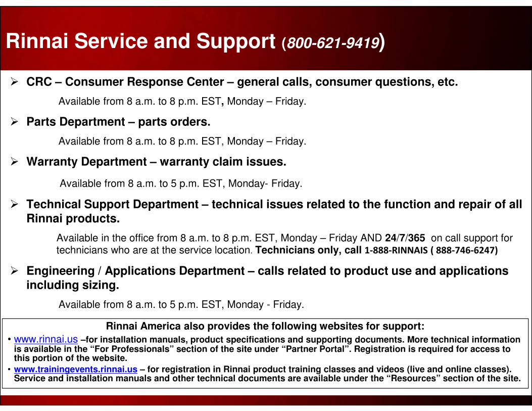
Rinnai Service and Support (800-621-9419)
� CRC – Consumer Response Center – general calls, consumer questions, etc.
Available from 8 a.m. to 8 p.m. EST, Monday – Friday.
� Parts Department – parts orders.
Available from 8 a.m. to 8 p.m. EST, Monday – Friday.
� Warranty Department – warranty claim issues.
Available from 8 a.m. to 5 p.m. EST, Monday- Friday.
� Technical Support Department – technical issues related to the function and repair of all Rinnai products.
Available in the office from 8 a.m. to 8 p.m. EST, Monday – Friday AND 24/7/365 on call support for technicians who are at the service location. Technicians only, call 1-888-RINNAIS ( 888-746-6247)
� Engineering / Applications Department – calls related to product use and applications including sizing.
Available from 8 a.m. to 5 p.m. EST, Monday - Friday.
Rinnai America also provides the following websites for support:
• www.rinnai.us –for installation manuals, product specifications and supporting documents. More technical information is available in the “For Professionals” section of the site under “Partner Portal”. Registration is required for access to this portion of the website.
• www.trainingevents.rinnai.us – for registration in Rinnai product training classes and videos (live and online classes). Service and installation manuals and other technical documents are available under the “Resources” section of the site.
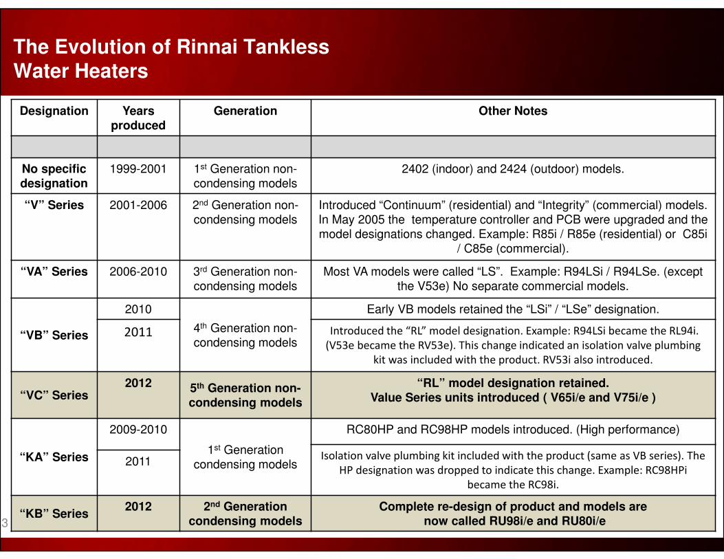
Designation Yearsproduced
Generation Other Notes
No specific designation
1999-2001 1st Generation non-condensing models
2402 (indoor) and 2424 (outdoor) models.
“V” Series 2001-2006 2nd Generation non-condensing models
Introduced “Continuum” (residential) and “Integrity” (commercial) models. In May 2005 the temperature controller and PCB were upgraded and the model designations changed. Example: R85i / R85e (residential) or C85i
/ C85e (commercial).
“VA” Series 2006-2010 3rd Generation non-condensing models
Most VA models were called “LS”. Example: R94LSi / R94LSe. (except the V53e) No separate commercial models.
“VB” Series
2010
4th Generation non-condensing models
Early VB models retained the “LSi” / “LSe” designation.
2011 Introduced the “RL” model designation. Example: R94LSi became the RL94i.
(V53e became the RV53e). This change indicated an isolation valve plumbing
kit was included with the product. RV53i also introduced.
“VC” Series2012 5th Generation non-
condensing models
“RL” model designation retained. Value Series units introduced ( V65i/e and V75i/e )
“KA” Series
2009-2010
1st Generation condensing models
RC80HP and RC98HP models introduced. (High performance)
Isolation valve plumbing kit included with the product (same as VB series). The
HP designation was dropped to indicate this change. Example: RC98HPi
became the RC98i.
2011
“KB” Series2012 2nd Generation
condensing modelsComplete re-design of product and models are
now called RU98i/e and RU80i/e
The Evolution of Rinnai Tankless Water Heaters
3
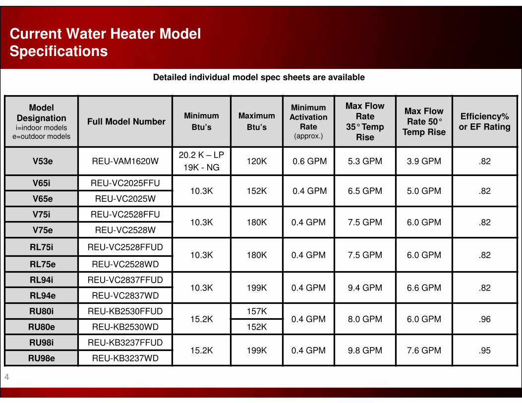
Model Designationi=indoor models
e=outdoor models
Full Model NumberMinimum
Btu’s
Maximum
Btu’s
Minimum Activation
Rate(approx.)
Max Flow Rate
35°Temp Rise
Max Flow Rate 50°
Temp Rise
Efficiency% or EF Rating
V53e REU-VAM1620W20.2 K – LP
19K - NG120K 0.6 GPM 5.3 GPM 3.9 GPM .82
V65i REU-VC2025FFU10.3K 152K 0.4 GPM 6.5 GPM 5.0 GPM .82
V65e REU-VC2025W
V75i REU-VC2528FFU10.3K 180K 0.4 GPM 7.5 GPM 6.0 GPM .82
V75e REU-VC2528W
RL75i REU-VC2528FFUD10.3K 180K 0.4 GPM 7.5 GPM 6.0 GPM .82
RL75e REU-VC2528WD
RL94i REU-VC2837FFUD10.3K 199K 0.4 GPM 9.4 GPM 6.6 GPM .82
RL94e REU-VC2837WD
RU80i REU-KB2530FFUD15.2K
157K0.4 GPM 8.0 GPM 6.0 GPM .96
RU80e REU-KB2530WD 152K
RU98i REU-KB3237FFUD15.2K 199K 0.4 GPM 9.8 GPM 7.6 GPM .95
RU98e REU-KB3237WD
Detailed individual model spec sheets are available
Current Water Heater Model Specifications
4

PRODUCT
FEATURES
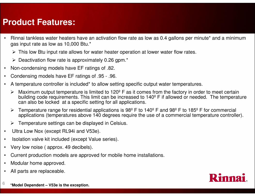
• Rinnai tankless water heaters have an activation flow rate as low as 0.4 gallons per minute* and a minimum
gas input rate as low as 10,000 Btu.*
� This low Btu input rate allows for water heater operation at lower water flow rates.
� Deactivation flow rate is approximately 0.26 gpm.*
• Non-condensing models have EF ratings of .82.
• Condensing models have EF ratings of .95 - .96.
• A temperature controller is included* to allow setting specific output water temperatures.
� Maximum output temperature is limited to 120º F as it comes from the factory in order to meet certain building code requirements. This limit can be increased to 140º F if allowed or needed. The temperature can also be locked at a specific setting for all applications.
� Temperature range for residential applications is 98º F to 140º F and 98º F to 185º F for commercial applications (temperatures above 140 degrees require the use of a commercial temperature controller).
� Temperature settings can be displayed in Celsius.
• Ultra Low Nox (except RL94i and V53e).
• Isolation valve kit included (except Value series).
• Very low noise ( approx. 49 decibels).
• Current production models are approved for mobile home installations.
• Modular home approved.
• All parts are replaceable.
*Model Dependent – V53e is the exception.
Product Features:
6

• Low voltage temperature controllers (12 VDC).
• Child / function lock capability on current models.
• Flame rod(s) validates presence of flame or indicates flame failure.
• Over heat bi-metal sensor(s).
• Integrated boiling protection.
• Heat exchanger thermal fuses.
• Leak detection with Luxury and Ultra Series internal units.
• Built-in freeze protection to -22º F for indoor units and -4º F for outdoor units (must have gas and electricity).
� A drain down kit can be obtained to protect the unit from freezing in case of electrical failure or inadequate gas supply—non-condensing models only.
• Combustion fan senses blocked intake or exhaust flue.
• Direct electronic ignition (no standing pilot).
• PC Board is protected by a glass fuse (fuse size will vary by model).
• Main components are monitored by the circuit board and will post an error code if a failure is detected.
Product Features / Safety Devices:
7
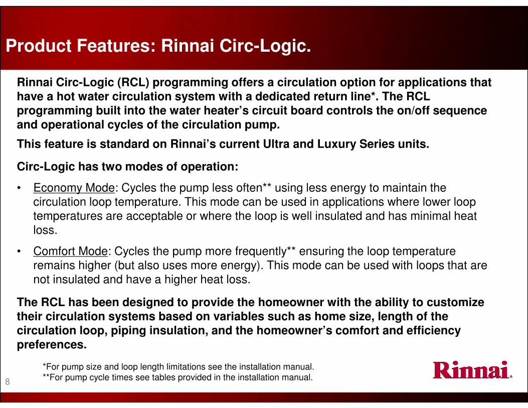
Product Features: Rinnai Circ-Logic.
Rinnai Circ-Logic (RCL) programming offers a circulation option for applications that have a hot water circulation system with a dedicated return line*. The RCL programming built into the water heater’s circuit board controls the on/off sequence and operational cycles of the circulation pump.
This feature is standard on Rinnai’s current Ultra and Luxury Series units.
*For pump size and loop length limitations see the installation manual.
**For pump cycle times see tables provided in the installation manual.
Circ-Logic has two modes of operation:
• Economy Mode: Cycles the pump less often** using less energy to maintain the circulation loop temperature. This mode can be used in applications where lower loop temperatures are acceptable or where the loop is well insulated and has minimal heat loss.
• Comfort Mode: Cycles the pump more frequently** ensuring the loop temperature remains higher (but also uses more energy). This mode can be used with loops that are not insulated and have a higher heat loss.
The RCL has been designed to provide the homeowner with the ability to customize their circulation systems based on variables such as home size, length of the circulation loop, piping insulation, and the homeowner’s comfort and efficiency preferences.
8
TANKLESS
WATER HEATER
SIZING
AND SEQUENCE
OF OPERATION

U.S. AVERAGE GROUND WATER TEMPERATURES
EXAMPLE: A home located in the St. Louis MO area....
Rinnai Tankless Water Heater’s temperature is set to 120°°°°
Subtract the incoming water temperature from the water heater’s set temperature to determine the ∆T: 120⁰ - 57⁰ = 63⁰
Delta T (∆T) is the difference between the incoming water temperature and the water heater’s set point temperature. The maximum flow rate available from a tankless water heater will depend on the Delta T.
What is Delta T ( ∆T )?
The average ground water temperature is 57°
10

The maximum flow rate for any given Delta T for a particular Rinnai water heater can be determined
using the flow chart for that model. The maximum flow rate can be found where the Delta T intersects
the flow curve on the chart.
� Example from the previous page: Incoming water = 57⁰ , Set-Point temperature = 120⁰, Delta T =63⁰
Maximum flow
rates can vary as
water temperatures
fluctuate throughout
the year.
Maximum Flow Rate:The tankless water heater’s priority is to provide hot water at the set temperature. The water heater may need to regulate or limit flow in order to maintain the selected output temperature.
Example #1: With a ∆T of 63º the
maximum flow rate would be 5.2 gpm
63
• In the first example, with a Delta T of 63⁰ F, the maximum flow rate is 5.2 GPM.
• In the second example if the incoming water was as warm as 80⁰F the Delta T would be 40⁰ F and the maxinum
flow rate would climb to 8.0 GPM.
• The installer will need to determine if these flow rates will be sufficient to meet the needs of the home or
business. If not, a larger unit or multiple units may be required.
40
Example #2: If the incoming water is 80°°°°
the ∆T would be 40º and the maximum flow
rate would be 8.0 gpm
Rinnai RL94 flow
curve illustrated
here.
11
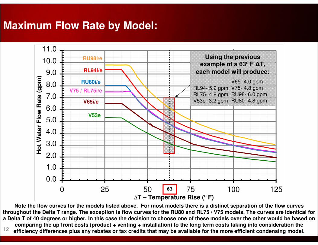
Note the flow curves for the models listed above. For most models there is a distinct separation of the flow curves throughout the Delta T range. The exception is flow curves for the RU80 and RL75 / V75 models. The curves are identical for a Delta T of 40 degrees or higher. In this case the decision to choose one of these models over the other would be based on
comparing the up front costs (product + venting + installation) to the long term costs taking into consideration the efficiency differences plus any rebates or tax credits that may be available for the more efficient condensing model.
Maximum Flow Rate by Model:
0.0
1.0
2.0
3.0
4.0
5.0
6.0
7.0
8.0
9.0
10.0
11.0
0 25 50 75 100 125∆T – Temperature Rise (⁰ F)
Ho
t W
ate
r F
low
Rate
(g
pm
)
RU98i/e
RL94i/e
V75 / RL75i/e
63
Using the previous example of a 63⁰ F ∆T,
each model will produce:
RL94- 5.2 gpmRL75- 4.8 gpm
V53e- 3.2 gpm
V53e
RU80i/e V65- 4.0 gpm
V75- 4.8 gpmRU98- 6.0 gpmRU80- 4.8 gpmV65i/e
12
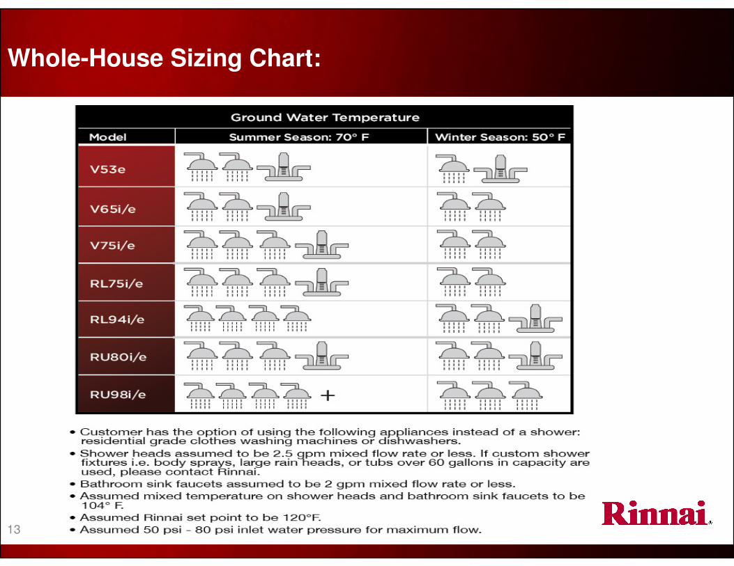
Whole-House Sizing Chart:
13
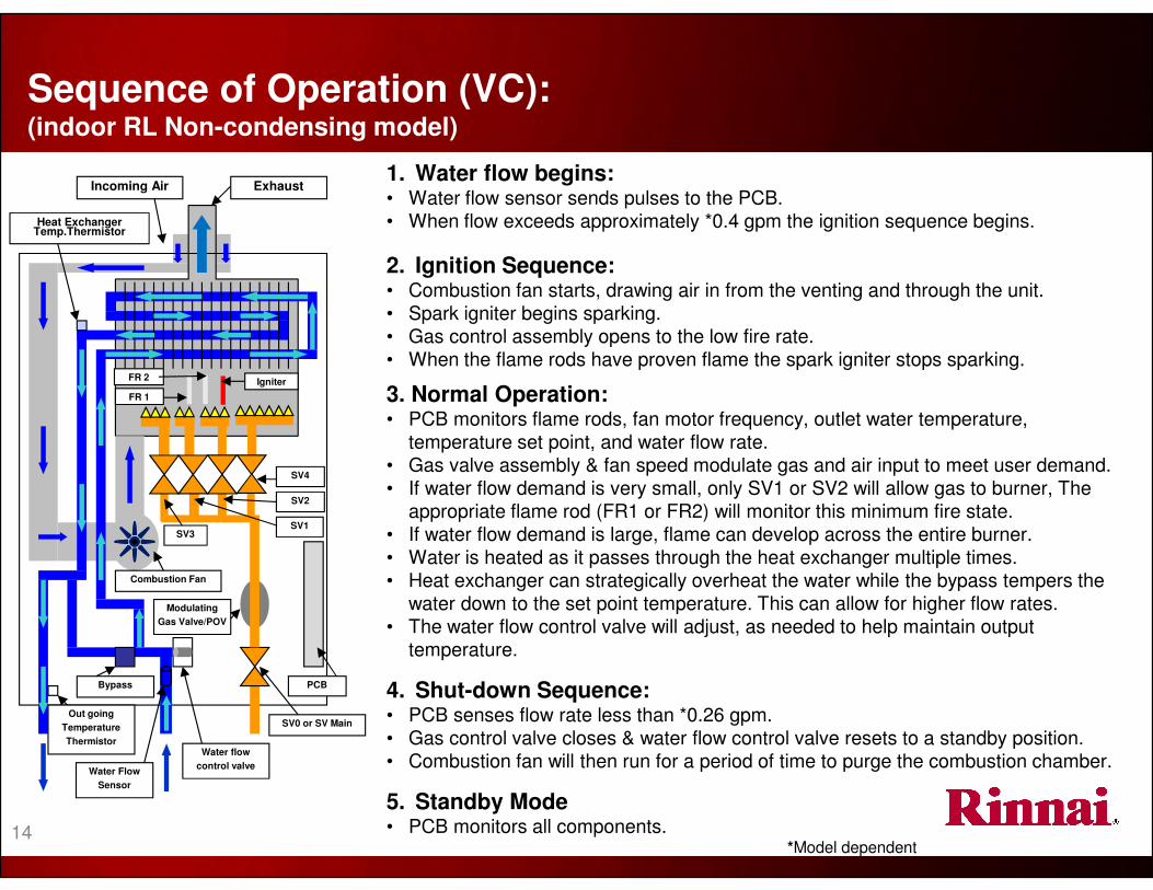
1. Water flow begins:• Water flow sensor sends pulses to the PCB.• When flow exceeds approximately *0.4 gpm the ignition sequence begins.
2. Ignition Sequence:• Combustion fan starts, drawing air in from the venting and through the unit.
• Spark igniter begins sparking. • Gas control assembly opens to the low fire rate.• When the flame rods have proven flame the spark igniter stops sparking.
3. Normal Operation:• PCB monitors flame rods, fan motor frequency, outlet water temperature,
temperature set point, and water flow rate.• Gas valve assembly & fan speed modulate gas and air input to meet user demand.• If water flow demand is very small, only SV1 or SV2 will allow gas to burner, The
appropriate flame rod (FR1 or FR2) will monitor this minimum fire state.• If water flow demand is large, flame can develop across the entire burner.• Water is heated as it passes through the heat exchanger multiple times.• Heat exchanger can strategically overheat the water while the bypass tempers the
water down to the set point temperature. This can allow for higher flow rates.• The water flow control valve will adjust, as needed to help maintain output
temperature.
4. Shut-down Sequence:• PCB senses flow rate less than *0.26 gpm. • Gas control valve closes & water flow control valve resets to a standby position.• Combustion fan will then run for a period of time to purge the combustion chamber.
5. Standby Mode• PCB monitors all components.
*Model dependent
Water Flow
Sensor
PCB
Combustion Fan
Igniter
SV4
SV0 or SV Main
Modulating
Gas Valve/POV
Water flow
control valve
Out going
Temperature
Thermistor
Incoming Air Exhaust
Heat Exchanger Temp.Thermistor
Bypass
Sequence of Operation (VC): (indoor RL Non-condensing model)
FR 2
FR 1
SV2
SV1SV3
14
TANKLESS WATER HEATER
INSTALLATION
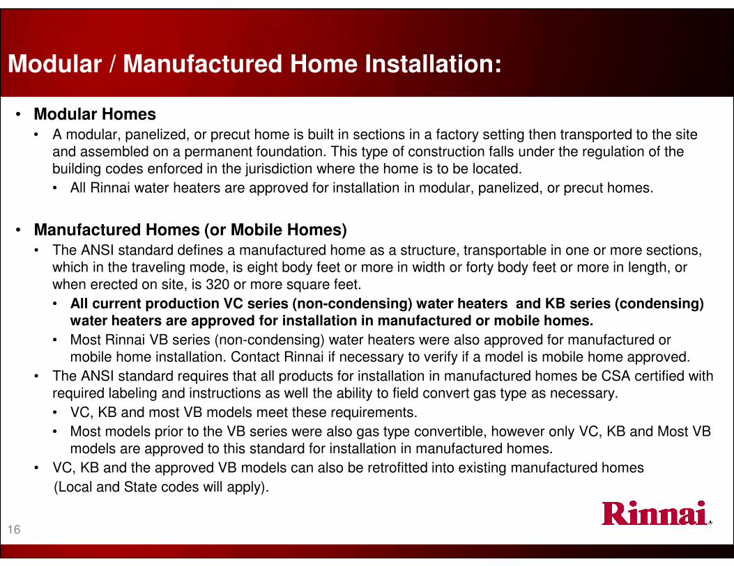
• Modular Homes• A modular, panelized, or precut home is built in sections in a factory setting then transported to the site
and assembled on a permanent foundation. This type of construction falls under the regulation of the
building codes enforced in the jurisdiction where the home is to be located.
• All Rinnai water heaters are approved for installation in modular, panelized, or precut homes.
• Manufactured Homes (or Mobile Homes)• The ANSI standard defines a manufactured home as a structure, transportable in one or more sections,
which in the traveling mode, is eight body feet or more in width or forty body feet or more in length, or
when erected on site, is 320 or more square feet.
• All current production VC series (non-condensing) water heaters and KB series (condensing) water heaters are approved for installation in manufactured or mobile homes.
• Most Rinnai VB series (non-condensing) water heaters were also approved for manufactured or
mobile home installation. Contact Rinnai if necessary to verify if a model is mobile home approved.
• The ANSI standard requires that all products for installation in manufactured homes be CSA certified with
required labeling and instructions as well the ability to field convert gas type as necessary.
• VC, KB and most VB models meet these requirements.
• Most models prior to the VB series were also gas type convertible, however only VC, KB and Most VB
models are approved to this standard for installation in manufactured homes.
• VC, KB and the approved VB models can also be retrofitted into existing manufactured homes
(Local and State codes will apply).
Modular / Manufactured Home Installation:
16

• Rinnai tankless water heaters can be used in both residential and commercial applications.
� except the Value Series, They are not to be used in commercial applications.
• Rinnai tankless water heaters are manufactured for either natural gas or propane.
• Indoor models must be installed within the confines of a structure. This includes carports and crawlspaces.
• Outdoor models must be installed outside.
• Residential installations are potable water applications in single family dwellings with a maximum water temperature setting of 140ºF.
• Commercial installations are potable water applications for restaurants, schools, hotels, car washes, coin laundries, assisted living facilities, etc. Hydronic applications are also defined as commercial installations.
• For commercial applications requiring water temperatures over 140º F, the optional MCC-91 temperature controller allows a maximum water temperature setting of 160º F (on the V53, V65, V75 and RL75 models) or a maximum setting of 185º F (on the RU80, RU98 and RL94 models).
Product Installation, Key Points:(All current Rinnai models)
DO NOT use Rinnai water heaters in any application involving chemically treated
water, (i.e. chlorinated pool water, hot tubs, etc,)17

It is important to ensure the following incoming sources fall within specifications:
• Electricity –
• A properly polarized and grounded 120 VAC, 60 Hz power supply is required (temperature
controllers operate on 12 VDC. This voltage is supplied by the water heater main circuit board).
• Water –
• Pipe sizing and incoming water pressure must meet each model’s requirements as stated in the installation manual and, water quality must meet the EPA’s National Secondary Drinking Standards.
• Gas –
• Adequate gas pressure and volume (gas line sizing) must be verified for proper operation.
• Venting (air) –• Only the vent components that are certified and listed with the water heater model must be installed. The venting must be installed to specifications and proper clearances must be maintained.
� All national, state, and local codes must be followed.
Installation Requirements:(All current models)
18
19
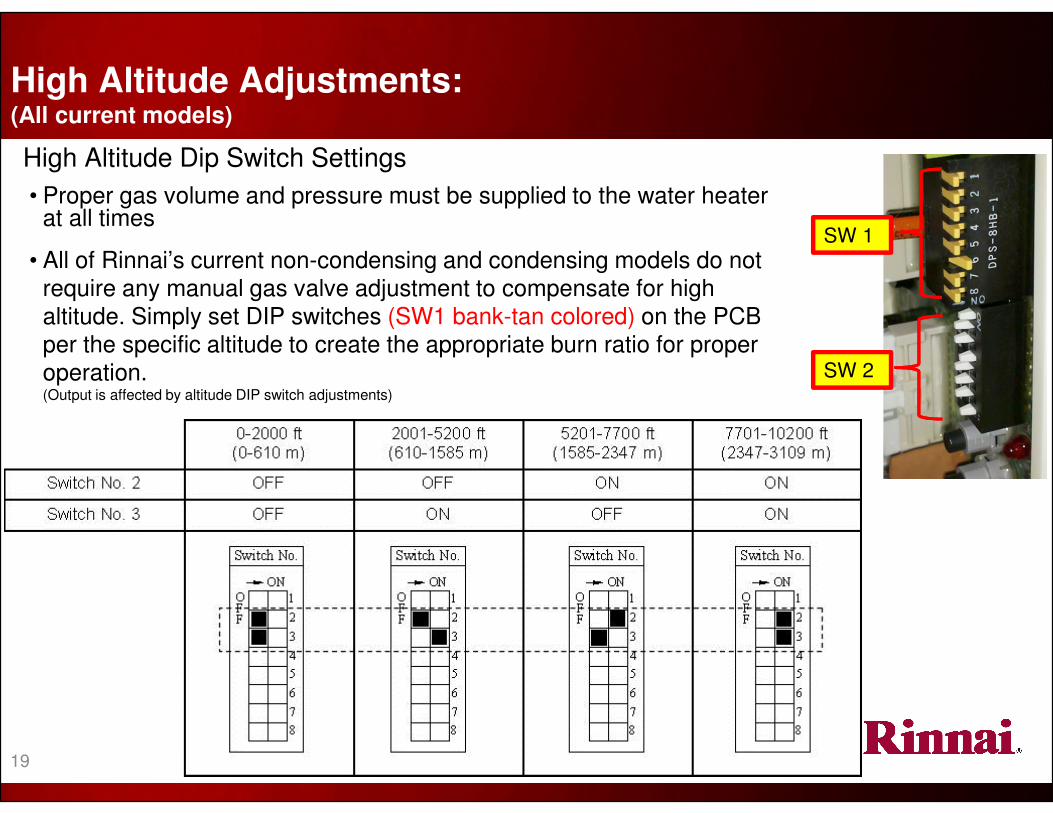
High Altitude Adjustments: (All current models)
High Altitude Dip Switch Settings
• Proper gas volume and pressure must be supplied to the water heater at all times
• All of Rinnai’s current non-condensing and condensing models do not require any manual gas valve adjustment to compensate for high altitude. Simply set DIP switches (SW1 bank-tan colored) on the PCB per the specific altitude to create the appropriate burn ratio for proper operation. (Output is affected by altitude DIP switch adjustments)
SW 1
SW 2

Tankless Valve Kit:
• Rinnai recommends the use of an isolation valve kit when connecting the water lines to the water heater.
• All RL94, RL75, RU98, and RU80 models now include Webstone Isolation Valve kits!
• This kit includes hot and cold water shut-off valves, hot and cold water drain valves, and an ANSI approved pressure relief valve.
• This kit meets all individual states’ lead-free standards.
• Use of this kit will allowflushing of the heat exchanger as well as aid in servicing and troubleshooting.
• This kit is not included withthe Value Series models.20

VENTING
REQUIREMENTS• It is imperative to ensure proper vent guidelines are followed.
• Ensure non-condensing and condensing guidelines are understood.
• Do not mix venting components between non-condensing and condensing models as dangerous conditions could occur!
! WARNING
Improper installation of vent system and components, or failure to follow all installation
instructions, can result in property damage or serious injury

• The above listed models use a concentric venting system which allows zero clearance from combustibles.
• These models are equipped with a female vent connection at the top of the water heater. Therefore, an appliance adaptor is NOT needed.
• These models also come equipped with an integrated condensation collector in the vent connector assembly.
The exhaust exits the appliance and the
structure from the center pipe
Fresh air enters
the appliance and
structure from the
outer pipe
This is a balanced flue system. The
incoming air keeps the outer pipe cool,
allowing zero clearance for the venting
system.
• Rinnai tankless water heaters are direct vent appliances and therefore are certified and listed with the vent system. Only vent components that are certified and listed with the water heater model should be used. Refer to the following table:
Listed and Tested Vent Products for the V65i, V75i, RL75i, and RL94i indoor models.
Manufacturer Product
Rinnai/Ubbink Rolux Vent System (available from Rinnai)
Heat-Fab Saf-T Vent SC system
Metal-Fab Corr/Guard Vent/Air Intake System
Intake / Exhaust Guidelines:For V53, V65, V75, RL75, and RL94 indoor models only
22

23
Vent Length Calculator – Indoor models:
= 6 Feet
= 3 Feet
• If the equivalency is greater than 21 feet, move DIP switch #1 on the PCB (bank of eight tan
colored) to the OFF position. (this switch is shipped in the ON position)
• Comply with all vent guidelines – refer to vent manufacturer and installation instructions.
• The water heater’s maximum water flow capacity will be reduced slightly when DIP switch no. 1 is OFF.
Add the total length of
all vent pipe and the
equivalency of all bends:
3’ (termination)
+3’ (bend)
+2’ (extension)
+3’ (bend)
+2’ (extension)
13 foot equivalency
S
w
i
t
c
h
N
u
m
b
e
r
→ ONO
F
F
1
2
3
4
5
6
7
8
Vent Length Example
2 feet
2 feet
3 feet
45°°°° bend = 3 feet
45°°°° bend = 3 feet
In this example, DIP switch #1
would remain in the ON position
• The maximum vent length for Non-condensing models is 41 equivalent feet.
• When calculating the equivalent vent length, each 90⁰ elbow is equal to 6 feet and each
45⁰ is equal to 3 feet.

2
4
Temperature Controllers
25
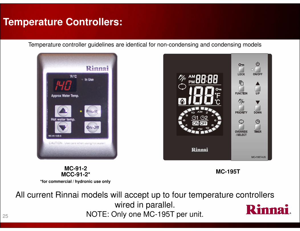
Temperature Controllers:
MC-91-2MCC-91-2*
*for commercial / hydronic use only
All current Rinnai models will accept up to four temperature controllers
wired in parallel. NOTE: Only one MC-195T per unit.
Temperature controller guidelines are identical for non-condensing and condensing models
MC-195T

When multiple controllers are
installed, the priority button
allows each to individually set
temperature output of the water
heater. The priority indicator
reports which controller has
control.
Indicates the selected
water temperature.
Diagnostic Codes flash if
operator intervention is
required.
ON/OFF BUTTONMODEL NUMBER
IN USE INDICATOR
Indicates that the unit is in
operation
TEMPERATURE INDICATION
THERMOSTAT
Increases or decreases the
desired water temperature
PRIORITY BUTTON & INDICATOR
MC-91-2/MCC-91-2 Temperature Controls:
26
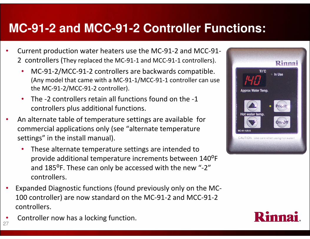
• Current production water heaters use the MC-91-2 and MCC-91-
2 controllers (They replaced the MC-91-1 and MCC-91-1 controllers).
• MC-91-2/MCC-91-2 controllers are backwards compatible. (Any model that came with a MC-91-1/MCC-91-1 controller can use
the MC-91-2/MCC-91-2 controller).
• The -2 controllers retain all functions found on the -1
controllers plus additional functions.
• An alternate table of temperature settings are available for
commercial applications only (see “alternate temperature
settings” in the install manual).
• These alternate temperature settings are intended to
provide additional temperature increments between 140⁰F
and 185⁰F. These can only be accessed with the new “-2”
controllers.
• Expanded Diagnostic functions (found previously only on the MC-
100 controller) are now standard on the MC-91-2 and MCC-91-2
controllers.
• Controller now has a locking function.
MC-91-2 and MCC-91-2 Controller Functions:
27

6/11/2014
Standard and Alternate Temperature Settings:
Standard Temperature Setting Range
Fahrenheit F° 98 100 102 104 106 108 110 115 120 125
*
130
*
135
*
140
*
150
**
160
**
185
**
Celsius C° 37 38 39 40 41 42 43 46 49 52 54 57 60 66 71 85
* Default maximum temperature is 120ºF. Temperature settings of 125ºF to 140ºF are available by setting
switch #6 to the ON position on SW1 (upper set of switches).
** Temperatures above 140ºF will require the use of a MCC-91 controller. When a MCC-91 controller is
connected, the higher temperatures will be available on all controllers in the same system.
Maximum temperature on some models will be limited to 160ºF.
Alternate Temperature Setting Range
Fahrenheit F° 110 115 120 125 130 135 140 145
*
150
*
155
*
160
*
165
*
170
*
175
*
180
*
185
*
Celsius C° 43 46 49 52 54 57 60 63 66 68 71 74 77 79 82 85
*Alternate temperature settings are available with MCC-91-2 controllers only.
Alternate temperature settings are for commercial applications only.
To select the alternate temperature settings, set dip switches #2 and #3 to the on position on SW2 (second or
lower set of switches).
NOTE: When alternate temperature settings are used, the minimum temperature setting will be 110ºF.
Alternate Settings
28
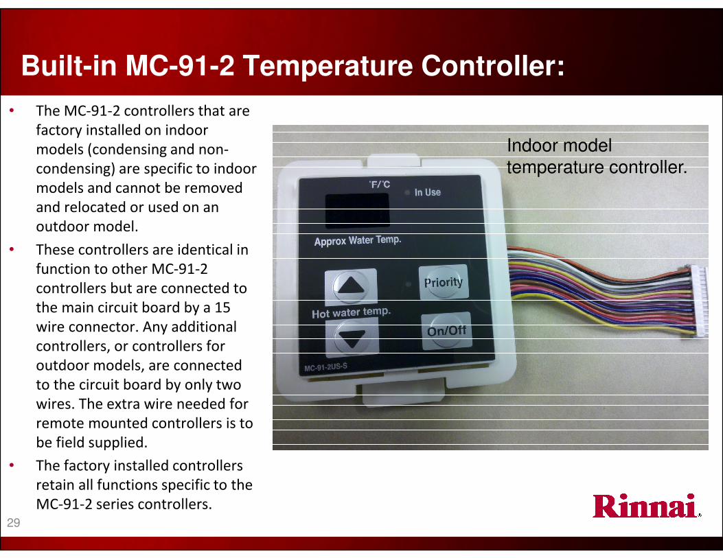
• The MC-91-2 controllers that are
factory installed on indoor
models (condensing and non-
condensing) are specific to indoor
models and cannot be removed
and relocated or used on an
outdoor model.
• These controllers are identical in
function to other MC-91-2
controllers but are connected to
the main circuit board by a 15
wire connector. Any additional
controllers, or controllers for
outdoor models, are connected
to the circuit board by only two
wires. The extra wire needed for
remote mounted controllers is to
be field supplied.
• The factory installed controllers
retain all functions specific to the
MC-91-2 series controllers.
Built-in MC-91-2 Temperature Controller:
Indoor model
temperature controller.
29
MC-195T Circulation Timer / Controller:
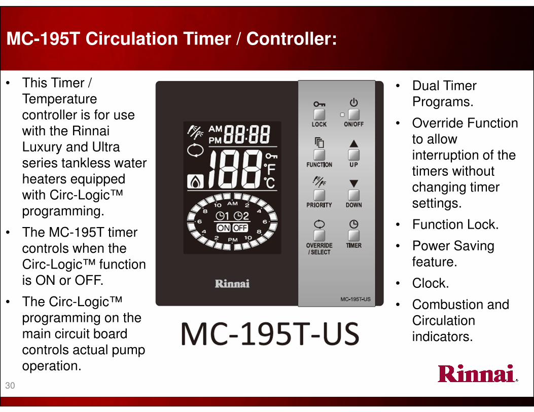
• This Timer /
Temperature controller is for use with the Rinnai
Luxury and Ultra series tankless water
heaters equipped
with Circ-Logic™
programming.
• The MC-195T timer
controls when the
Circ-Logic™ function is ON or OFF.
• The Circ-Logic™ programming on the
main circuit board controls actual pump
operation.
• Dual Timer
Programs.
• Override Function to allow
interruption of the timers without
changing timer
settings.
• Function Lock.
• Power Saving
feature.
• Clock.
• Combustion and Circulation
indicators.
30
31
Temperature Controllers (continued):
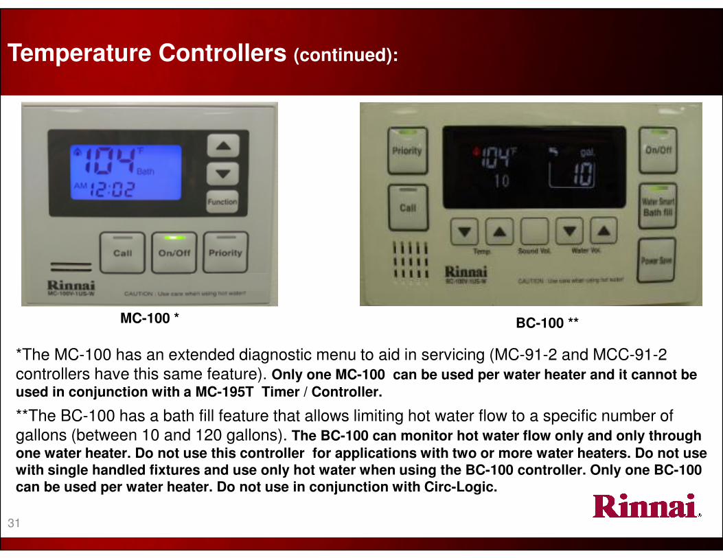
MC-100 * BC-100 **
*The MC-100 has an extended diagnostic menu to aid in servicing (MC-91-2 and MCC-91-2 controllers have this same feature). Only one MC-100 can be used per water heater and it cannot be
used in conjunction with a MC-195T Timer / Controller.
**The BC-100 has a bath fill feature that allows limiting hot water flow to a specific number of gallons (between 10 and 120 gallons). The BC-100 can monitor hot water flow only and only through
one water heater. Do not use this controller for applications with two or more water heaters. Do not use with single handled fixtures and use only hot water when using the BC-100 controller. Only one BC-100 can be used per water heater. Do not use in conjunction with Circ-Logic.

3
2
32
• All water heaters* manufactured in July, 2008 or later have the following temperature adjustment feature:
� Maximum default temperature setting of 120⁰F (49º C).
Temperature Controller Range:(for all current Rinnai Water Heaters)
S
w
i
t
c
h
N
u
m
b
e
r
→ ON
O
F
F
1
2
3
4
5
6
7
8
• Meets the requirements of
various local codes.
• Enhances the safety of
users, especially children.
• Temperature settings
between 125ºF and 140ºF
(52º - 60ºC) are available by
setting DIP switch 6 to the
ON position in the SW1
bank of 8 (upper set) DIP
switches.
*The V53e does come with a temperature controller. This model can be set at 120⁰ or 140⁰ by a dip switch setting. If a MC-91 controller
is connected it will not default at a
max of 120º. These models will max
at 140º. DIP switch 6 is allocated for
another use.

Warranty

[1] Period of coverage is reduced to 3 years from date of purchase when used as a circulating water heater within a hot water circulation loop where the water heater is in series with a circulation system and where all circulating water flows through the water heater and where an on-demand circulation system is not incorporated.
• Note: The warranty for a condensing model heat exchanger used in a circulation system which is controlled through an aquastat / thermostat, or timer, or an on-demand system is 12 years for residential applications.
• Heat exchanger warranty for the Value series is 10 years but will increase to 12 years if a isolation valve kit is installed.
• If a Rinnai water heater is used in a commercial application, the commercial warranty will apply. Exception: V53,V65, and V75 models are not approved for commercial applications.
[2] Period of coverage is reduced to 5 years from date of purchase if the Rinnai water heater temperature setting exceeds 160ºF (71⁰C).
[3] Labor coverage is extended to 5 years in residential applications and 2 years in commercial applications if the product is registered within 30 days (registration not required in California and Quebec) and/or if the other conditions above in the Residential and Commercial applications are satisfied.
� Warranty covers any defects in materials or workmanship when the product is installed and operated according to Rinnai written installation instructions
� Warranty applies only to products that are installed per local and/or state codes. Improper installation may void the warranty.
� Warranty doesn’t cover failure due to accident, abuse, misuse, alteration, misapplication, force majeure, improper installation,maintenance, or service, inadequate water quality, scale buildup, or freeze damage
� There is no warranty coverage on product installed in a closed loop application commonly associated with space heating only applications.
� This warranty does not cover any product used in an application that uses chemically treated water such as a pool or spa heater.
� The integrated controller on indoor models has a 1 year warranty on parts.
Item
Period of coverage (from date of purchase)
Residential ApplicationsBoth residential water heating and
space heating applicationsCommercial Applications
Heat Exchanger 12 years (10 years Value Series) [1] [2] 10 years [1] [2] 5 years [1]
Other parts and components 5 years [1] 5 years [1] 5 years [1]
Reasonable Labor 1 year [3] 1 year [3] 1 year [3]
Warranty: (see owner’s manual for complete warranty guidelines)*
34
Rinnai Condensing
Water Heater
Differences
The following slides highlight some of the operation and installation differences plus some of the similarities
between condensing water heaters as compared to non-condensing models.
Please read the installation manual that comes with each product for more specific information.

DIFFERENCES:
• Energy Factor rating as high as .96 (model dependent).
• Higher EF ratings could qualify for rebates and/or tax incentives.
• Integrated condensation trap—no need to address condensation in the vent system.
� Draining direct to a drain system is permitted but a neutralizer may be required (check with local codes).
• Listed vent systems are different than Rinnai’s non-condensing water heaters.
• Stainless steel secondary heat exchanger (primary heat exchanger is copper).
SIMILARITIES:
• Energy Star Qualified—Eligible for various utility and tax incentives.
• Activation flow rate of 0.4 GPM.
• Deactivation flow rate of 0.26 GPM.
• Current Rinnai temperature controllers are used with the condensing series.
� Diagnostic codes are displayed on the controller.
• Venting clearances and equivalencies are similar to Rinnai’s non-condensing water heaters.
• Rinnai condensing water heaters are approved for installations up to 10,200 feet.
� The same altitude setting procedures exist for condensing models.
Condensing Model Product Features:Similarities and differences compared to Rinnai’s non-condensing products
36

• When combustion occurs, there will always be some
level of heat loss in the form of hot exhaust exiting the
appliance through the vent system.
• The efficiency of a gas-fired appliance is measured by
how much heat is actually transferred to the heating
medium (water, air, etc) and how much is lost through
the vent system.
(2) 165K Btu are transferred into
the water
(3) Approximately 34K Btu escape through the exhaust
This heat exchanger is
83% efficient.165K ÷÷÷÷ 199K = .83
• Condensing appliances capture extra heat (or
latent heat) before it escapes into the vent
system and transfers it, in the case of a water
heater, into the water being heated.
• Capturing this extra heat cools the exhaust
gasses below the dew point. Below the dew
point any water vapor in the exhaust turns to
liquid (condenses). This condensate
combines with other combustion by-products
to form an acid solution. Condensing
appliances are designed to properly drain this
condensation.
(3) 165K Btu are transferred in the
primary heat exchanger
(4) 189K Btu are transferred into
the water
(2) 24K Btu are transferred in the secondary (or latent)
heat exchanger
(5) Approximately 10K Btu escape through the
exhaust
(1) 199K Btu of gas enter the
heat exchanger
Non-condensing Water Heater
Condensing Water Heater
Condensing Technology:
This heat exchanger is 95% efficient. (24K +
165K) ÷÷÷÷ 199K = .95
(1) 199K Btu of gas enter the heat exchanger
37
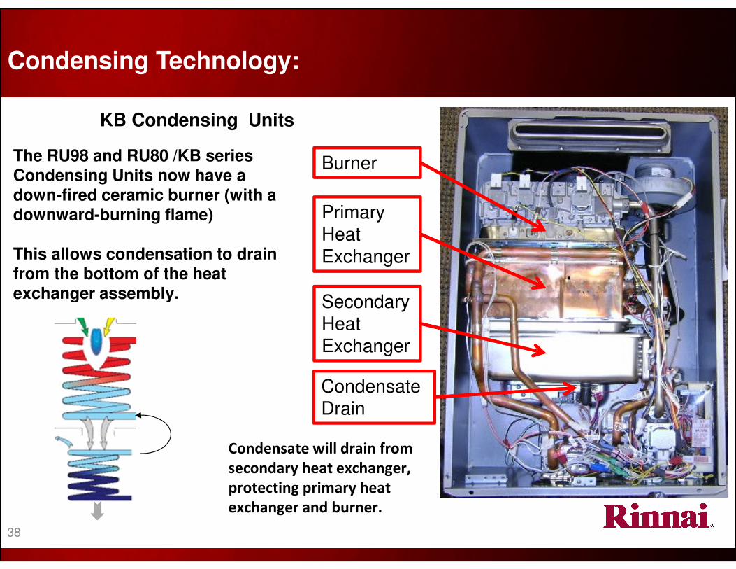
The RU98 and RU80 /KB series Condensing Units now have a down-fired ceramic burner (with a downward-burning flame)
This allows condensation to drain from the bottom of the heat exchanger assembly.
Condensate will drain from
secondary heat exchanger,
protecting primary heat
exchanger and burner.
KB Condensing Units
Condensing Technology:
Burner
Primary Heat
Exchanger
Secondary
Heat
Exchanger
Condensate
Drain
38
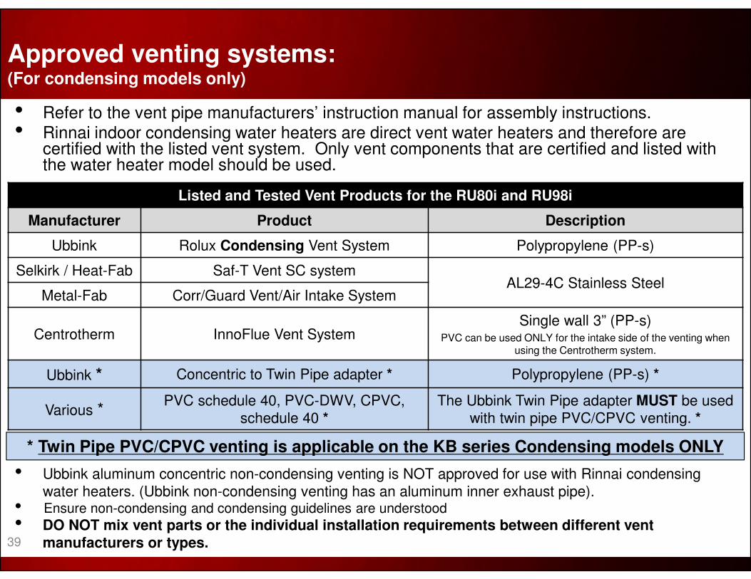
• Refer to the vent pipe manufacturers’ instruction manual for assembly instructions.• Rinnai indoor condensing water heaters are direct vent water heaters and therefore are
certified with the listed vent system. Only vent components that are certified and listed with the water heater model should be used.
Listed and Tested Vent Products for the RU80i and RU98i
Manufacturer Product Description
Ubbink Rolux Condensing Vent System Polypropylene (PP-s)
Selkirk / Heat-Fab Saf-T Vent SC systemAL29-4C Stainless Steel
Metal-Fab Corr/Guard Vent/Air Intake System
Centrotherm InnoFlue Vent SystemSingle wall 3” (PP-s)
PVC can be used ONLY for the intake side of the venting when using the Centrotherm system.
Ubbink * Concentric to Twin Pipe adapter * Polypropylene (PP-s) *
Various *PVC schedule 40, PVC-DWV, CPVC,
schedule 40 *The Ubbink Twin Pipe adapter MUST be used
with twin pipe PVC/CPVC venting. *
• Ubbink aluminum concentric non-condensing venting is NOT approved for use with Rinnai condensing
water heaters. (Ubbink non-condensing venting has an aluminum inner exhaust pipe). • Ensure non-condensing and condensing guidelines are understood
• DO NOT mix vent parts or the individual installation requirements between different vent manufacturers or types.
Approved venting systems:(For condensing models only)
* Twin Pipe PVC/CPVC venting is applicable on the KB series Condensing models ONLY
39

40
Warning label on each individual vent piece.
Condensing Concentric Venting Parts:(For Condensing models only)
When purchasing or using Rinnai/Ubbink venting, ensure the proper vent material is used.
• The shipping box for the Rinnai/Ubbink polypropylene (PP-s) venting will have an asterisk on the part number label and the label description will read “Condensing”.
• Each Rinnai/Ubbink PP-s condensing vent component will have an orange/green warning Label on the outer/intake pipe and an orange/black label on the inner/exhaust pipe (inside label may be difficult to see).
Inside pipe
Outside pipe
Labeling on shipping box.
Product descriptionAsterisk for condensing venting

Additional Rinnai Water
Heating Options
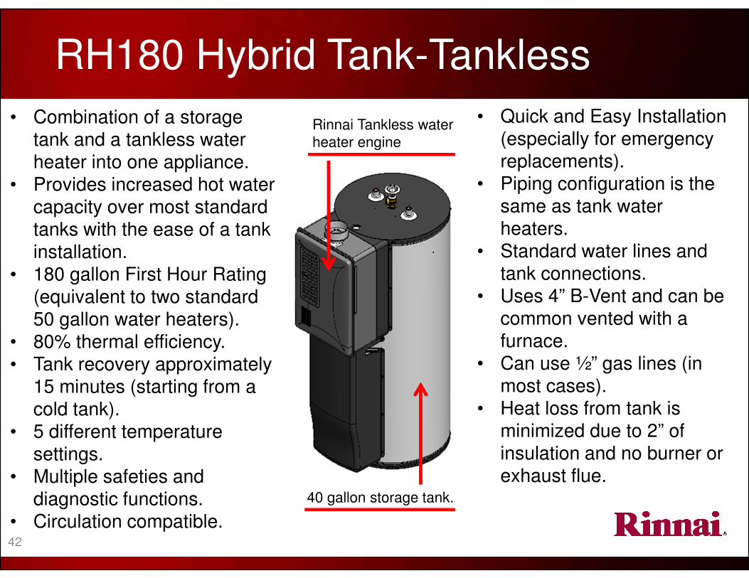
RH180 Hybrid Tank-Tankless
Rinnai Tankless water
heater engine
40 gallon storage tank.
• Quick and Easy Installation
(especially for emergency replacements).
• Piping configuration is the
same as tank water heaters.
• Standard water lines and
tank connections.
• Uses 4” B-Vent and can be common vented with a
furnace.
• Can use ½” gas lines (in most cases).
• Heat loss from tank is
minimized due to 2” of insulation and no burner or
exhaust flue.
• Combination of a storage
tank and a tankless water heater into one appliance.
• Provides increased hot water capacity over most standard tanks with the ease of a tank installation.
• 180 gallon First Hour Rating
(equivalent to two standard 50 gallon water heaters).
• 80% thermal efficiency.
• Tank recovery approximately 15 minutes (starting from a
cold tank).
• 5 different temperature settings.
• Multiple safeties and diagnostic functions.
• Circulation compatible. 42
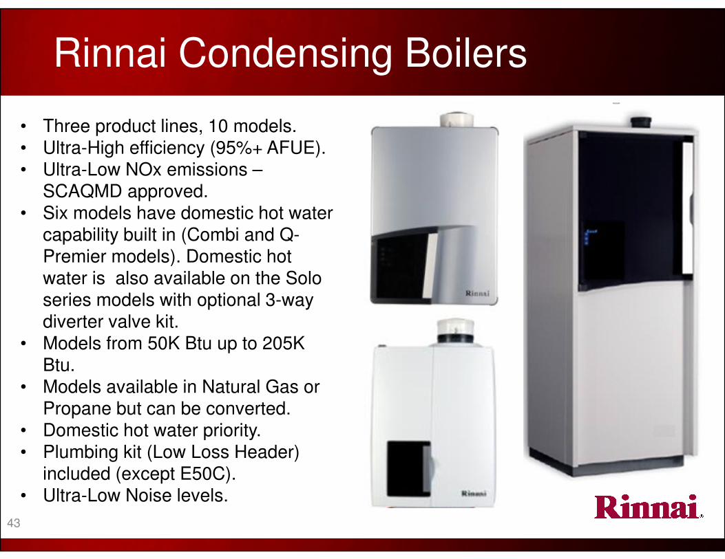
Rinnai Condensing Boilers
• Three product lines, 10 models.
• Ultra-High efficiency (95%+ AFUE).• Ultra-Low NOx emissions –
SCAQMD approved. • Six models have domestic hot water
capability built in (Combi and Q-
Premier models). Domestic hot
water is also available on the Solo series models with optional 3-way
diverter valve kit.
• Models from 50K Btu up to 205K Btu.
• Models available in Natural Gas or
Propane but can be converted. • Domestic hot water priority.
• Plumbing kit (Low Loss Header) included (except E50C).
• Ultra-Low Noise levels.
43

MANUFACTURER
ACCESSORIES

Condensation Neutralizer Kit:
Features and Benefits• Raises pH before discharging condensate into drain
• Clear Capsule – Easy to identify need for new media
• For Condensing Boilers and Condensing Water Heaters• Can mount vertically and horizontally
• Fast and simple installation
• Refillable – Easy and inexpensive
• Capacity 1.6 Gallons/Hour (6.06 liters/hour)
P/N 804000074 P/N 809000114
45

Domestic Priority Switch (DPS) / Maintenance Indication Switch:
This switch is intended to be installed in a Rinnai tankless water heater when connected to one of the following products or systems…………
• The switch can be used when a Rinnai tanklesswater heater is used in conjunction with a Rinnai or other branded hydronic air handler. The switch provides for domestic hot water priority and will turn the air handler off during high domestic hot water demands and allow it to come back on when the demand is reduced.
• The switch can also be used to connect a Rinnai water heater to a simple building management system. The switch will signal the building management system if an error code causes the water heater to shut down (it indicates only that a water heater is not operating, not what the actual fault code is).
The switch is a volt-free Normally Open (NO) / Normally Closed
(NC) switch.
P/N 103000037
46
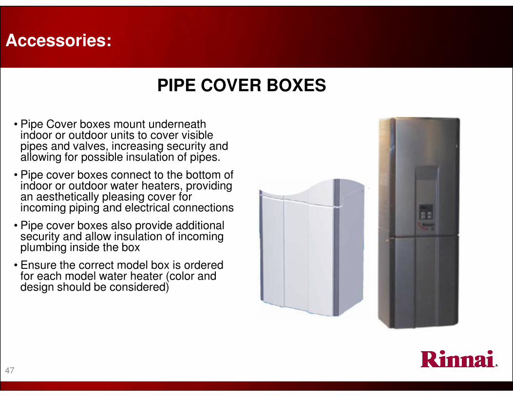
PIPE COVER BOXES
• Pipe Cover boxes mount underneath indoor or outdoor units to cover visible pipes and valves, increasing security and allowing for possible insulation of pipes.
• Pipe cover boxes connect to the bottom of indoor or outdoor water heaters, providing an aesthetically pleasing cover for incoming piping and electrical connections
• Pipe cover boxes also provide additional security and allow insulation of incoming plumbing inside the box
• Ensure the correct model box is ordered for each model water heater (color and design should be considered)
Accessories:
47
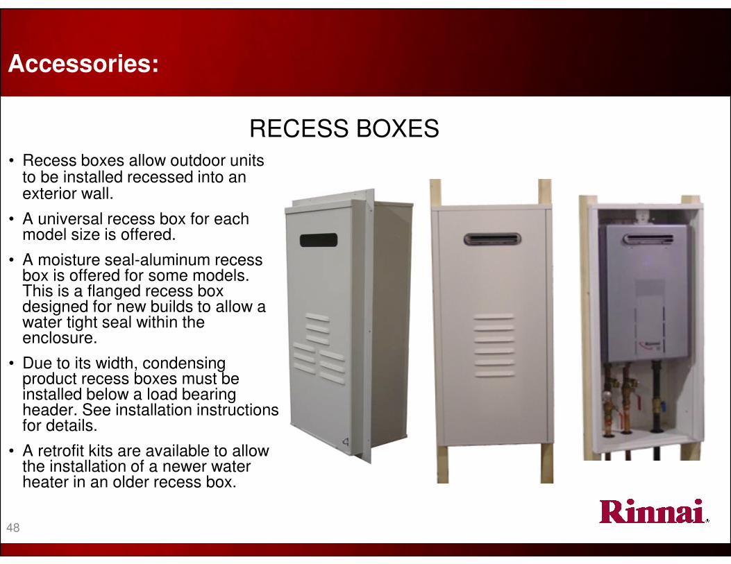
RECESS BOXES• Recess boxes allow outdoor units
to be installed recessed into an exterior wall.
• A universal recess box for each model size is offered.
• A moisture seal-aluminum recess box is offered for some models. This is a flanged recess box designed for new builds to allow a water tight seal within the enclosure.
• Due to its width, condensing product recess boxes must be installed below a load bearing header. See installation instructions for details.
• A retrofit kits are available to allow the installation of a newer water heater in an older recess box.
Accessories:
48

49
Recess / Pipe Cover Compatibility Parts List
PIPE COVER / RECESS BOX COMPATIBILITY
Model Pipe Cover Boxes Recess Boxes
V53e PC-20-W RGB-20U
V65e and V75e PCD03-EWV RGB-25U-C
R75LSe / RL75e
PCD03-SM2
RGB-25U or
RGB-25U-MSAL
MSAL=Moisture Seal AluminumR94LSe / RL94e
R98LSe or R98LSe ASME PC-32-S RGB-32-W
RC80e PCD07-SMBottom plate sold separately-PCD07-SM-BP
RGB-CWTHRC98e
RL75e and RL94e (VA,VB,VC) PCD03-SM2 RGB-25U-C
RU80e or RU98e (KB series) PCD07-SM RGB-CTWH-2
V65i and V75i PCD03-EWV
Not Applicable
R75LSi / RL75i PCD03-SM2(use PCD03-SM for 2009 models or earlier)R94LSi / RL94i
R98LSi or R98LSi ASME PC-32-S
RC80i / RU80i PCD07-SM
Bottom plate sold separately-PCD07-SM-BPRC98i / RU98i
The below chart shows applicable part numbers for each model:

Multiple unit installations
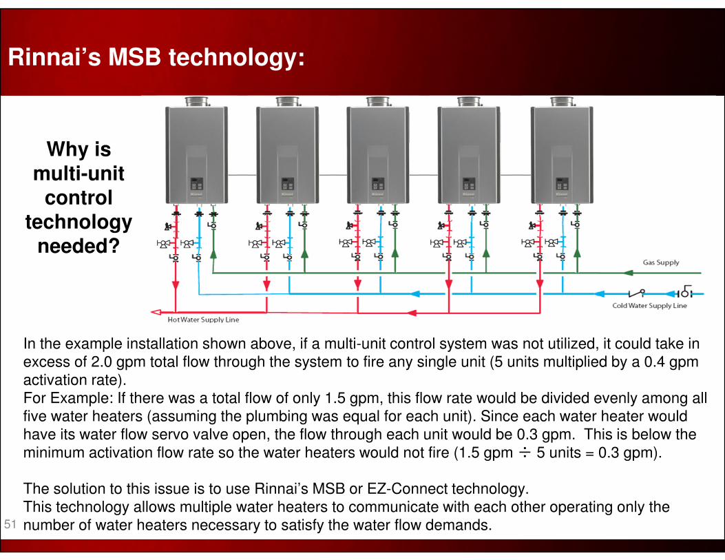
Why is multi-unit
control technology
needed?
In the example installation shown above, if a multi-unit control system was not utilized, it could take in excess of 2.0 gpm total flow through the system to fire any single unit (5 units multiplied by a 0.4 gpm activation rate). For Example: If there was a total flow of only 1.5 gpm, this flow rate would be divided evenly among all five water heaters (assuming the plumbing was equal for each unit). Since each water heater would have its water flow servo valve open, the flow through each unit would be 0.3 gpm. This is below the
minimum activation flow rate so the water heaters would not fire (1.5 gpm ÷ 5 units = 0.3 gpm).
The solution to this issue is to use Rinnai’s MSB or EZ-Connect technology. This technology allows multiple water heaters to communicate with each other operating only the number of water heaters necessary to satisfy the water flow demands.
Rinnai’s MSB technology:
51

Rinnai’s MSB technology:
The main component of Rinnai’s MSB technology is
the MSB circuit board. This board can be used to link
up to 5 water heaters. The board is mounted inside one water heater and is connected to other units by a
wire harness. The basic MSB-M kit contains all parts needed to link two water heaters. Additional wire
harnesses will be needed for additional water
heaters.
Cables linking the MSB to other water heaters.
This picture illustrates how a MSB board will be installed in a VC series indoor water heater.
52
53
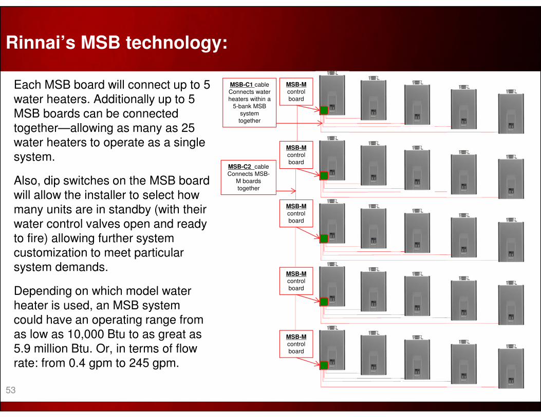
Each MSB board will connect up to 5 water heaters. Additionally up to 5 MSB boards can be connected together—allowing as many as 25 water heaters to operate as a single system.
Also, dip switches on the MSB board will allow the installer to select how many units are in standby (with their water control valves open and ready to fire) allowing further system customization to meet particular system demands.
Depending on which model water heater is used, an MSB system could have an operating range from as low as 10,000 Btu to as great as 5.9 million Btu. Or, in terms of flow rate: from 0.4 gpm to 245 gpm.
Rinnai’s MSB technology:
MSB-M
control
board
MSB-M
control
board
MSB-M
control
board
MSB-M
control
board
MSB-M
control
board
MSB-C1 cable
Connects water
heaters within a
5-bank MSB
system
together
MSB-C2 cable
Connects MSB-
M boards
together

Dip Sw 5 ON 1 unit in standby (allow for quicker activation for flow rates within the capacity of a single unit)
Dip Sw 5 OFF(default)
Both units in standby (allows for quicker delivery temperature for higher flow rates requiring both units)
For VB, VC, KA or KB series units: Dip Switch 5 in the SW2 bank of 6 (white switches) will control whether one or both units are ready to fire when in standby:
EZConnectstandby setting
NOTE: This Dip Switch will not affect systems operating with an MSA / MSB board
When connecting only two
water heaters, an MSB board is not necessary. An EZConnect cable can be
used. It connects to a special harness on the
primary water heater and to
the PCB on the secondary
unit (see pictures). Three or more water heaters will
require the use of an MSB
system.
EZ-Connect Connection
EZConnectConnection
EZConnect® – Connecting (only) two water heaters:
54
This concludes the Rinnai
Tankless Water Heater Training Program
Level I - Product Knowledge
101101, 2/2014