RINGFEDER Products are available from MARYLAND … the applicable machining tolerance for the shaft...
44
LOCKING ELEMENTS TM LOCKING ASSEMBLIES TM SHRINK DISCS ® W-300-2 RINGFEDER ® KEYLESS SHAFT/HUB CONNECTIONS RINGFEDER Products are available from MARYLAND METRICS P.O. Box 261 Owings Mills, MD 21117 USA email: [email protected] web: http://mdmetric.com phones: (410)358-3130 (800)638-1830 faxes: (410)358-3142 (800)872-9329
Transcript of RINGFEDER Products are available from MARYLAND … the applicable machining tolerance for the shaft...
LOCKING ELEMENTSTM
LOCKING ASSEMBLIESTM
SHRINK DISCS®
W-300-2
RINGFEDER®
KEYLESS SHAFT/HUBCONNECTIONS
RINGFEDER Products are available from MARYLAND METRICSP.O. Box 261 Owings Mills, MD 21117 USA email: [email protected] web: http://mdmetric.com
phones: (410)358-3130 (800)638-1830 faxes: (410)358-3142 (800)872-9329

2 Catalog W-300-2
1 Ringfeder CorporationCatalog W-300-1Shaft-Hub Locking Devices
Ringfeder® unique frictional, keyless shaft-hub locking devices provide an easilyadjustable and releasable mechanical shrink-fit. They offer all the advantages ofshrink-fits – without the problems. Torque or axial loads are transmitted by radialclamping pressures and friction between the functional surfaces of the locking device,shaft and hub.
Working PrincipleRingfeder® shaft-hub locking devices are based on the inclined plane or taper princi-ple. Clamping forces generated by torqued up locking screws are translated into pre-determined contact pressures so as to create mechanical shrink-fit connections.
ApplicationsRingfeder® frictional shaft-hub locking devices have successfully solved shaft-hubconnection problems involving:Gears Rolls CamsLevers Winches SprocketsFlanges Couplings Brake drumsSheaves Flywheels Hand wheelsClutches Fan wheels Worm gearsBevel gears Helical gears Mixer shaftsCrane wheels Bucket wheels Pump impellersTurbine rotors Conveyer pulleys Ship propellersWindmill propellers Rock-cutting heads Shaft-mounted gear units
Advantages• Elimination of keys, keyways or splines and associated fitting costs• Completely tight fit around shaft – no backlash• Impervious to reversing, dynamic or shock loads• Transmission of high torques and axial loads
Benefits• Reduced machining costs• Easy installation, assembly and disassembly• Easy axial and angular adjustments and timing
RINGFEDER Products are available from MARYLAND METRICSP.O. Box 261 Owings Mills, MD 21117 USA email: [email protected] web: http://mdmetric.com
phones: (410)358-3130 (800)638-1830 faxes: (410)358-3142 (800)872-9329
3Catalog W-300-2
2
3
4
5
6
7
910
7a
8
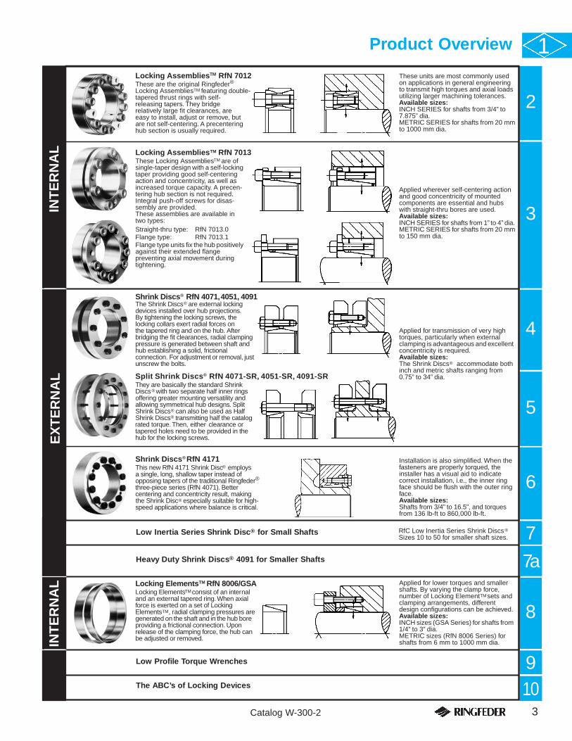
Locking Assemblies RfN 7012These are the original Ringfeder® Locking Assemblies featuring double-tapered thrust rings with self-releasing tapers. They bridge relatively large fit clearances, are easy to install, adjust or remove, but are not self-centering. A precentering hub section is usually required.
These units are most commonly used on applications in general engineering to transmit high torques and axial loads utilizing larger machining tolerances.Available sizes:INCH SERIES for shafts from 3/4” to 7.875” dia.METRIC SERIES for shafts from 20 mm to 1000 mm dia.
Locking Assemblies RfN 7013These Locking Assemblies are of single-taper design with a self-locking taper providing good self-centering action and concentricity, as well as increased torque capacity. A precen-tering hub section is not required. Integral push-off screws for disas-sembly are provided.These assemblies are available in two types:Straight-thru type: RfN 7013.0Flange type: RfN 7013.1Flange type units fix the hub positively against their extended flange preventing axial movement during tightening.
Applied wherever self-centering action and good concentricity of mounted components are essential and hubs with straight-thru bores are used.Available sizes:INCH SERIES for shafts from 1” to 4” dia.METRIC SERIES for shafts from 20 mm to 150 mm dia.
INT
ER
NA
LTM
TM
TM
TM
Applied for lower torques and smaller shafts. By varying the clamp force, number of Locking Element sets and clamping arrangements, different design configurations can be achieved.Available sizes:INCH sizes (GSA Series) for shafts from 1/4” to 3” dia.METRIC sizes (RfN 8006 Series) for shafts from 6 mm to 1000 mm dia.
Locking Elements RfN 8006/GSALocking Elements consist of an internal and an external tapered ring. When axial force is exerted on a set of Locking Elements , radial clamping pressures are generated on the shaft and in the hub boreproviding a frictional connection. Upon release of the clamping force, the hub can be adjusted or removed.IN
TE
RN
AL TM
TM
TM
TM
RfC Low Inertia Series Shrink Discs Sizes 10 to 50 for smaller shaft sizes.
®
Shrink Discs RfN 4071, 4051, 4091The Shrink Discs are external locking devices installed over hub projections. By tightening the locking screws, the locking collars exert radial forces on the tapered ring and on the hub. After bridging the fit clearances, radial clamping pressure is generated between shaft and hub establishing a solid, frictional connection. For adjustment or removal, just unscrew the bolts.
Applied for transmission of very high torques, particularly when external clamping is advantageous and excellent concentricity is required.Available sizes:The Shrink Discs accommodate both inch and metric shafts ranging from 0.75” to 34” dia.
RfC Low Inertia Series Shrink Discs Sizes 10 to 50 for smaller shaft sizes.
Installation is also simplified. When the fasteners are properly torqued, the installer has a visual aid to indicate correct installation, i.e., the inner ring face should be flush with the outer ring face.Available sizes: Shafts from 3/4” to 16.5”, and torques from 136 lb-ft to 860,000 lb-ft.
Split Shrink Discs RfN 4071-SR, 4051-SR, 4091-SRThey are basically the standard Shrink Discs with two separate half inner ringsoffering greater mounting versatility and allowing symmetrical hub designs. Split Shrink Discs can also be used as Half Shrink Discs transmitting half the catalog rated torque. Then, either clearance or tapered holes need to be provided in the hub for the locking screws.
Shrink Discs RfN 4171This new RfN 4171 Shrink Disc employs a single, long, shallow taper instead of opposing tapers of the traditional Ringfeder®three-piece series (RfN 4071). Better centering and concentricity result, making the Shrink Disc especially suitable for high-speed applications where balance is critical.
,
EX
TE
RN
AL
®
®
®
®
®
®
®
®
®
®
®
Product Overview 1
Low Inertia Series Shrink Disc® for Small Shafts
Low Profile Torque Wrenches
The ABC’s of Locking Devices
Heavy Duty Shrink Discs® 4091 for Smaller Shafts

4 Catalog W-300-2
2 Ringfeder®
Locking AssembliesTM
RfN 7012 & RfN 7012-IN
Ringfeder® Locking AssembliesTM are completely self-contained, frictional shaft-hub locking devices. Designed to generate an easily adjustable and releasable mechanical shrink-fit, they have been used successfully for many years in heavy-duty applications to transmit high torques and dynamic loads and to provide timingand releasability.
Application Examples
Fig. 1: Drive PulleyDrive pulley with 280 mm dia. (11.024”)Locking AssembliesTM and bend pulleywith 95 mm dia. (3.740”) LockingAssembliesTM.
Fig. 3: GearsGears fitted with RfN 7012Locking AssembliesTM.
Fig. 2: Lower Band WheelsLower band wheels of a twin band sawfastened with 7” RfN 7012-IN LockingAssembliesTM.
Fig. 4: SprocketsInput shaft for 750 HP draw works showingapplications of Locking AssembliesTM andadaptor flanges.
Fig. 7: Cutter HeadsCutter heads fastened with Locking AssembliesTM.
Fig. 5: DrivePulleyDrive pulley of agondola ski liftfastened with a300 x 375 RfN7012 LockingAssemblyTM.
Fig. 6: Pinion GearPinion gear and flywheel both mountedwith RfN 7012 Locking AssembliesTM.
RINGFEDER Products are available from MARYLAND METRICSP.O. Box 261 Owings Mills, MD 21117 USA email: [email protected] web: http://mdmetric.com
phones: (410)358-3130 (800)638-1830 faxes: (410)358-3142 (800)872-9329

5Catalog W-300-2
Selection Guide 21. Determine the required shaft diameter (d) or
maximum torque (Mt) to be transmitted:
Torque Mt = 5252 x HP (lb-ft)RPM
If combined torsional and axial loads are to be trans-mitted, calculate the resulting torque as follows:
Mt res = Mt2 + (Pax x d)2
≤ Mt cat24
Mt res = resultant torque to be transmittedMt = actual or maximum torque to be
transmitted (lb-ft)Pax = axial load/thrust to be transmitted (lbs)d = shaft diameter (inches)Mt cat = maximum transmissible torque (lb-ft) of
Locking AssemblyTM as specified
2. Select a Locking AssemblyTM for the shaft diameter(d) from the specification tables and verify that thecorresponding maximum transmissible torque (Mt)meets the torque requirement.If torque is the primary requirement, select the neces-sary torque (Mt) from the same specification tablesand determine the corresponding shaft diameter (d).Note: Required peak torque should never exceed specifiedtransmissible torque (Mt).
To increase transmissible torque (Mt):a. Install 2 or 3 Locking AssembliesTM in series,
increasing transmissible torque as follows:- with 2 Locking AssembliesTM: Mtrans.= 2 x Mt- with 3 Locking AssembliesTM: Mtrans.= 3 x Mt
- (see Fig. 8: Hub Layout and Fig. 9).The hub must be long enough to accommodatethe assemblies.
b. Increase screw tightening torque (MA) by up to20%. Transmissible torque (Mt) and contactpressures (p, p’) increase proportionately.
3. Determine the recommended minimum hub outsidediameter (DN) for the Locking AssemblyTM selectedfrom the specification tables or calculate the hub out-side diameter (DN) by using the following equation:
DN ≥ D x YP + C3 x p’YP - C3 x p’
Where YP = yield point of hub material (lbs/sq.in.)p’ = p x d/D (lbs/sq.in.)B = ≥ min. 2 x I (inches); see ExampleC3 = 0.6 (one locking assembly)C3 = 0.8 (2 or 3 Locking AssembliesTM in series)
4. Verify that the hub length (B) is adequate for theselected Locking AssemblyTM; see Example.
5. Check the applicable machining tolerance for theshaft and hub bore in the specification tables. A sur-face finish of 125 micro-inches for shafts and bores isgenerally adequate.
6. Determine the required Locking AssemblyTM by speci-fying the size (d x D) from Tables 1 & 2 followed bythe series number, e.g.: 100 x 145 RfN 7012.
Note: When accurate centering of the hub is required,establish a proper fit tolerance for the pilot or centering portion of the hub.
√
EXAMPLEA spur gear is to be mounted on a 3.9375” dia. shaft capable oftransmitting a peak torque of 5,750 lb-ft. The gear is made of 1040AISI steel (Y.P. 36,000 psi). Select the proper Locking AssemblyTM
and determine the required hub dimensions and proper machiningtolerances.
1. The shaft diameter is specified at 3.9375”.
2. The specification tables indicate that a 3-15/16 LockingAssemblyTM is capable of transmitting a torque (Mt) of 6,944lb-ft, more than the required amount. Select the 3-15/16Locking AssemblyTM.
3. The specification tables indicate that the selected 3-15/16Locking AssemblyTM requires a minimum hub outer diameter of8.000” based on Y.P. 36,000 psi hub material.
4. The hub length (B) should be 2 x L1. Fig. 8 indicates that L1 =1.852”. Therefore, B = 2 x 1.852” = 3.704” (minimum).
Since the gear must be concentric within .0025”, specify thefollowing fit tolerance for the pilot bore:
shaft: 3.9375/3.9365”bore: 3.9375/3.9390”
5. According to the specification tables, the machining tolerancesfor the selected Locking AssemblyTM are as follows:
shaft: +.000/-.0035”counter bore: -.000/+.0035”
However, because of the concentricity requirements for the gear,tighter tolerances are needed for the shaft and pilot bore.
The counter bore tolerances for the Locking AssemblyTM are -.0000/+.0025” (within the permissible limits and in accordancewith the fit tolerance specified in Step 4 above).
6. Order the following assembly:Size RfN Series
Metric: 100 x 145 RfN 7012Inch: 3-15/16 RfN 7012-IN
√
Fig. 8: Hub LayoutTypical layout for a Locking AssemblyTM installation.
6 Catalog W-300-2
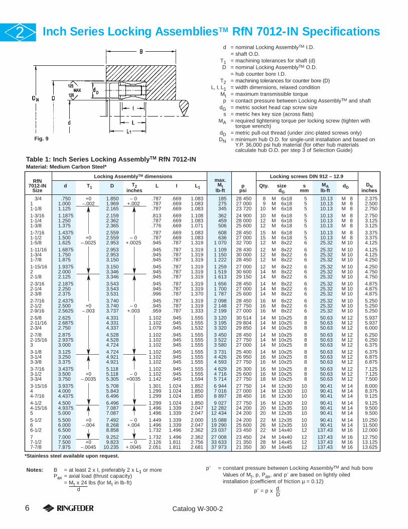
Inch Series Locking AssembliesTM RfN 7012-IN Specifications2
Notes: B = at least 2 x I, preferably 2 x L1 or morePax = axial load (thrust capacity)
= Mt x 24 lbs (for Mt in lb-ft)d
p’ = constant pressure between Locking AssemblyTM and hub boreValues of Mt, p, Pax, and p’ are based on lightly oiled installation (coefficient of friction µ = 0.12)
p’ = p x dD
1-3/4 .750 +0 1.850 – 0 .787 .669 1.083 185 28 450 8 M 6x18 5 10.13 M 8 2.3751 1.000 –.002 1.969 +.002 .787 .669 1.083 275 27 000 9 M 6x18 5 10.13 M 8 2.5001-1/8 1.125 2.165 .787 .669 1.083 345 23 720 10 M 6x18 5 10.13 M 8 2.7501-3/16 1.1875 2.159 .813 .669 1.108 362 24 900 10 M 6x18 5 10.13 M 8 2.7501-1/4 1.250 2.362 .787 .669 1.083 459 28 000 12 M 6x18 5 10.13 M 8 3.1251-3/8 1.375 2.365 .776 .669 1.071 506 25 600 12 M 6x18 5 10.13 M 8 3.1251-7/16 1.4375 2.559 .787 .669 1.083 608 28 450 15 M 6x18 5 10.13 M 8 3.3751-1/2 1.500 +0 2.559 – 0 .787 .669 1.083 636 27 000 15 M 6x18 5 10.13 M 8 3.3751-5/8 1.625 –.0025 2.953 +.0025 .945 .787 1.319 1 070 32 700 12 M 8x22 6 25.32 M 10 4.1251-11/16 1.6875 2.953 .945 .787 1.319 1 109 28 430 12 M 8x22 6 25.32 M 10 4.1251-3/4 1.750 2.953 .945 .787 1.319 1 150 30 000 12 M 8x22 6 25.32 M 10 4.1251-7/8 1.875 3.150 .945 .787 1.319 1 222 28 450 12 M 8x22 6 25.32 M 10 4.2501-15/16 1.9375 3.150 .945 .787 1.319 1 259 27 000 12 M 8x22 6 25.32 M 10 4.2502 2.000 3.346 .945 .787 1.319 1 519 30 600 14 M 8x22 6 25.32 M 10 4.7502-1/8 2.125 3.346 .945 .787 1.319 1 613 29 150 14 M 8x22 6 25.32 M 10 4.7502-3/16 2.1875 3.543 .945 .787 1.319 1 656 28 450 14 M 8x22 6 25.32 M 10 4.8752-1/4 2.250 3.543 .945 .787 1.319 1 700 27 000 14 M 8x22 6 25.32 M 10 4.8752-3/8 2.375 3.531 .996 .787 1.370 1 787 25 600 14 M 8x22 6 25.32 M 10 4.8752-7/16 2.4375 3.740 .945 .787 1.319 2 098 28 450 16 M 8x22 6 25.32 M 10 5.2502-1/2 2.500 +0 3.740 – 0 .945 .787 1.319 2 148 27 750 16 M 8x22 6 25.32 M 10 5.2502-9/16 2.5625 –.003 3.737 +.003 .959 .787 1.333 2 199 27 000 16 M 8x22 6 25.32 M 10 5.2502-5/8 2.625 4.331 1.102 .945 1.555 3 120 30 514 14 M 10x25 8 50.63 M 12 5.9372-11/16 2.6875 4.331 1.102 .945 1.555 3 195 29 804 14 M 10x25 8 50.63 M 12 5.9372-3/4 2.750 4.337 1.079 .945 1.532 3 320 29 850 14 M 10x25 8 50.63 M 12 6.0002-7/8 2.875 4.528 1.102 .945 1.555 3 450 28 450 14 M 10x25 8 50.63 M 12 6.2502-15/16 2.9375 4.528 1.102 .945 1.555 3 522 27 750 14 M 10x25 8 50.63 M 12 6.2503 3.000 4.724 1.102 .945 1.555 3 580 27 000 14 M 10x25 8 50.63 M 12 6.3753-1/8 3.125 4.724 1.102 .945 1.555 3 731 25 400 14 M 10x25 8 50.63 M 12 6.3753-1/4 3.250 4.921 1.102 .945 1.555 4 426 26 950 16 M 10x25 8 50.63 M 12 6.8753-3/8 3.375 4.921 1.102 .945 1.555 4 593 27 750 16 M 10x25 8 50.63 M 12 6.8753-7/16 3.4375 5.118 1.102 .945 1.555 4 629 26 300 16 M 10x25 8 50.63 M 12 7.1253-1/2 3.500 +0 5.118 – 0 1.102 .945 1.555 4 716 25 600 16 M 10x25 8 50.63 M 12 7.1253-3/4 3.750 –.0035 5.305 +0035 1.142 .945 1.594 5 714 27 750 18 M 10x25 8 50.63 M 12 7.5003-15/16 3.9375 5.708 1.301 1.024 1.852 6 944 27 750 14 M 12x30 10 90.41 M 14 8.0004 4.000 5.843 1.299 1.024 1.850 7 016 27 000 14 M 12x30 10 90.41 M 14 8.3754-7/16 4.4375 6.496 1.299 1.024 1.850 8 897 28 450 16 M 12x30 10 90.41 M 14 9.1254-1/2 4.500 6.496 1.299 1.024 1.850 9 027 27 750 16 M 12x30 10 90.41 M 14 9.1254-15/16 4.9375 7.087 1.496 1.339 2.047 12 282 24 200 20 M 12x35 10 90.41 M 14 9.5005 5.000 7.087 1.496 1.339 2.047 12 434 24 200 20 M 12x35 10 90.41 M 14 9.5005-1/2 5.500 +0 7.492 – 0 1.449 1.339 2.000 15 088 24 200 22 M 12x35 10 90.41 M 14 10.2506 6.000 –.004 8.268 +.004 1.496 1.339 2.047 19 290 25 600 26 M 12x35 10 90.41 M 14 11.5006-1/2 6.500 8.858 1.732 1.496 2.362 23 037 23 450 22 M 14x40 12 137.43 M 16 12.0007 7.000 9.252 1.732 1.496 2.362 27 008 23 450 24 M 14x40 12 137.43 M 16 12.7507-1/2 7.500 +0 9.823 – 0 2.126 1.811 2.756 33 633 21 350 28 M 14x45 12 137.43 M 16 13.1257-7/8 7.875 –.0045 10.235 +.0045 2.051 1.811 2.681 37 973 21 350 30 M 14x45 12 137.43 M 16 13.625
d = nominal Locking AssemblyTM I.D.= shaft O.D.
T1 = machining tolerances for shaft (d)D = nominal Locking AssemblyTM O.D.
= hub counter bore I.D.T2 = machining tolerances for counter bore (D)
L, I, L1 = width dimensions, relaxed conditionMt = maximum transmissible torquep = contact pressure between Locking AssemblyTM and shaft
dG = metric socket head cap screw sizes = metric hex key size (across flats)
MA = required tightening torque per locking screw (tighten withtorque wrench)
dD = metric pull-out thread (under zinc-plated screws only)DN = minimum hub O.D. for single-unit installation and based on
Y.P. 36,000 psi hub material (for other hub materials calculate hub O.D. per step 3 of Selection Guide)
Fig. 9
Locking AssemblyTM dimensions Locking screws DIN 912 – 12.9RfN max.
7012-IN d T1 D T2 L I L1 Mt p Qty. size s MA dD DNSize inches lb-ft psi dG mm lb-ft inches
*Stainless steel available upon request.
Table 1: Inch Series Locking AssemblyTM RfN 7012-INMaterial: Medium Carbon Steel*

7Catalog W-300-2
Metric Series Locking AssembliesTM RfN 7012 Specifications 2
Ordering ExampleSize RfN Series
Metric: 100 x 145 RfN 7012Inch: 3-15/16 RfN 7012-IN
20 x 47 .787 1.850 .787 .669 1.083 195 29 850 8 M 6x18 5 10.13 M 8 2.37522 x 47 .866 +0 1.850 – 0 .787 .669 1.083 217 27 750 8 M 6x18 5 10.13 M 8 2.37524 x 50 .945 –.002 1.969 +.002 .787 .669 1.083 260 27 750 9 M 6x18 5 10.13 M 8 2.500
25 x 50 .984 1.969 .787 .669 1.083 275 27 000 9 M 6x18 5 10.13 M 8 2.50028 x 55 1.102 2.165 .787 .669 1.083 340 26 300 9 M 6x18 5 10.13 M 8 2.75030 x 55 1.181 2.165 .787 .669 1.083 362 24 900 9 M 6x18 5 10.13 M 8 2.750
32 x 60 1.260 2.362 .787 .669 1.083 456 26 397 12 M 6x18 5 10.13 M 8 3.12535 x 60 1.378 +0 2.362 – 0 .787 .669 1.083 506 25 600 12 M 6x18 5 10.13 M 8 3.12538 x 65 1.496 –.0025 2.559 +.0025 .787 .669 1.083 630 27 628 15 M 6x18 5 10.13 M 8 3.375
40 x 65 1.575 2.559 .787 .669 1.083 665 25 600 15 M 6x18 5 10.13 M 8 3.37542 x 75 1.654 2.953 .945 .787 1.319 1 085 32 634 12 M 8x22 6 25.32 M 10 4.12545 x 75 1.772 2.953 .945 .787 1.319 1 165 29 850 12 M 8x22 6 25.32 M 10 4.125
48 x 80 1.890 3.150 .945 .787 1.319 1 230 28 428 12 M 8x22 6 25.32 M 10 4.25050 x 80 1.969 3.150 .945 .787 1.319 1 280 27 000 12 M 8x22 6 25.32 M 10 4.25055 x 85 2.165 3.346 .945 .787 1.319 1 642 28 450 14 M 8x22 6 25.32 M 10 4.750
60 x 90 2.362 3.543 .945 .787 1.319 1 787 25 600 14 M 8x22 6 25.32 M 10 4.87565 x 95 2.559 +0 3.740 – 0 .945 .787 1.319 2 199 27 000 16 M 8x22 6 25.32 M 10 5.25070 x 110 2.756 –.003 4.331 +.003 1.102 .945 1.555 3 327 29 850 14 M 10x25 8 50.63 M 12 6.000
75 x 115 2.953 4.528 1.102 .945 1.555 3 544 27 750 14 M 10x25 8 50.63 M 12 6.25080 x 120 3.150 4.724 1.102 .945 1.555 3 761 25 600 14 M 10x25 8 50.63 M 12 6.37585 x 125 3.346 4.921 1.102 .945 1.555 4 557 27 750 16 M 10x25 8 50.63 M 12 6.875
90 x 130 3.543 5.118 1.102 .945 1.555 4 774 25 600 16 M 10x25 8 50.63 M 12 7.12595 x 135 3.740 +0 5.315 – 0 1.102 .945 1.555 5 714 27 750 18 M 10x25 8 50.63 M 12 7.500
100 x 145 3.937 –.0035 5.709 +.0035 1.229 1.024 1.850 6 944 27 750 14 M 12x30 10 90.41 M 14 8.000
110 x 155 4.331 6.102 1.229 1.024 1.850 7 595 25 600 14 M 12x30 10 90.41 M 14 8.375120 x 165 4.724 6.496 1.229 1.024 1.850 9 475 26 300 16 M 12x30 10 90.41 M 14 9.125130 x 180 5.118 7.087 1.496 1.339 2.047 12 730 23 450 20 M 12x35 10 90.41 M 14 9.500
140 x 190 5.512 7.480 1.496 1.339 2.047 15 117 23 450 22 M 12x35 10 90.41 M 14 10.250150 x 200 5.906 +0 7.874 – 0 1.496 1.339 2.047 17 504 24 200 24 M 12x35 10 90.41 M 14 10.750160 x 210 6.299 –.004 8.268 +.004 1.496 1.339 2.047 20 252 24 200 26 M 12x35 10 90.41 M 14 11.500
170 x 225 6.693 8.858 1.732 1.496 2.362 23 724 22 750 22 M 14x40 12 137.43 M 16 12.000180 x 235 7.087 9.252 1.732 1.496 2.362 27 341 23 750 24 M 14x40 12 137.43 M 16 12.750190 x 250 7.480 9.843 2.047 1.811 2.677 33 633 21 350 28 M 14x45 12 137.43 M 16 13.125
200 x 260 7.874 +0 10.236 – 0 2.047 1.811 2.677 37 973 21 350 30 M 14x45 12 137.43 M 16 13.625220 x 285 8.661 –.0045 11.220 +.0045 2.205 1.969 2.913 49 184 21 350 26 M 16x50 14 213.37 M 20 15.000240 x 305 9.449 12.008 2.205 1.969 2.913 61 842 22 750 30 M 16x50 14 213.37 M 20 16.500
260 x 325 10.236 +0 12.795 – 0 2.205 1.969 2.913 75 223 23 450 34 M 16x50 14 213.37 M 20 17.750280 x 355 11.024 –.005 13.976 +.005 2.598 2.362 3.406 92 582 20 600 32 M 18x60 14 292.94 M 22 18.625300 x 375 11.811 14.764 2.598 2.362 3.406 110 665 21 350 36 M 18x60 14 292.94 M 22 20.000
320 x 405 12.598 15.945 3.071 2.835 3.957 151 893 21 350 36 M 20x70 17 419.51 M 24 21.500340 x 425 13.386 +0 16.732 – 0 3.071 2.835 3.957 162 019 20 600 36 M 20x70 17 419.51 M 24 22.250360 x 455 14.173 –.0055 17.913 +.0055 3.543 3.307 4.567 212 650 20 600 36 M 22x80 17 564.17 M 27 23.875
380 x 475 14.961 18.701 3.543 3.307 4.567 222 776 19 200 36 M 22x80 17 564.17 M 27 24.625400 x 495 15.748 19.488 3.543 3.307 4.567 232 903 18 500 36 M 22x80 17 564.17 M 27 25.250420 x 515 16.535 20.276 3.543 3.307 4.567 270 514 19 200 40 M 22x80 17 564.17 M 27 26.625
440 x 545 17.323 +0 21.457 – 0 4.016 3.780 5.118 329 102 18 500 40 M 24X90 19 723.30 M 30 27.750460 x 565 18.110 –.006 22.244 +.006 4.016 3.780 5.118 339 951 17 800 40 M 24X90 19 723.30 M 30 28.625480 x 585 18.898 23.031 4.016 3.780 5.118 372 450 17 800 42 M 24X90 19 723.30 M 30 29.625500 x 605 19.685 23.819 4.016 3.780 5.118 405 048 17 800 44 M 24X90 19 723.30 M 30 30.625
RfN Locking AssemblyTM dimensions Locking screws DIN 912 – 12.97012 max.Size d T1 D T2 L I L1 Mt p Qty. size s MA dD DNmm inches lb-ft psi dG mm lb-ft inches
*Stainless steel available upon request.For larger sizes or additional information, request catalog S76A.
Table 2: Metric Series Locking AssemblyTM RfN 7012Material: Medium Carbon Steel*
8 Catalog W-300-2
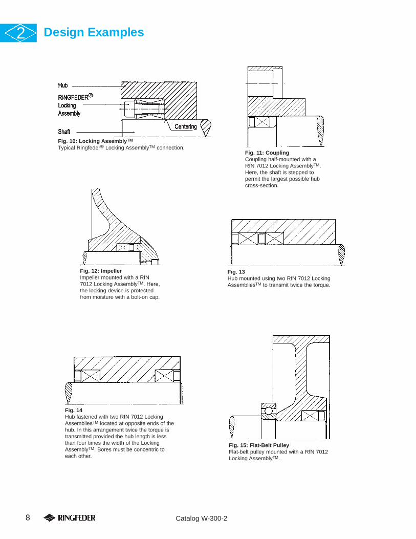
Design Examples2
Fig. 11: CouplingCoupling half-mounted with aRfN 7012 Locking AssemblyTM.Here, the shaft is stepped topermit the largest possible hubcross-section.
Fig. 12: ImpellerImpeller mounted with a RfN7012 Locking AssemblyTM. Here,the locking device is protectedfrom moisture with a bolt-on cap.
Fig. 13Hub mounted using two RfN 7012 LockingAssembliesTM to transmit twice the torque.
Fig. 15: Flat-Belt PulleyFlat-belt pulley mounted with a RfN 7012Locking AssemblyTM.
Fig. 14Hub fastened with two RfN 7012 LockingAssembliesTM located at opposite ends of thehub. In this arrangement twice the torque istransmitted provided the hub length is lessthan four times the width of the LockingAssemblyTM. Bores must be concentric to each other.
Fig. 10: Locking AssemblyTM
Typical Ringfeder® Locking AssemblyTM connection.

REMOVALRingfeder® Locking AssembliesTM are not self-locking. Theindividual rings are tapered so that the inner and outer ringsspring apart after the last screw has been loosened.1 Loosen the locking screws in several steps
following a diametrically opposite sequence. Do not remove the screws completely.
2 Remove the hub and Locking AssemblyTM from the shaft.
REMOVAL TOOL• Three pull-out bolts or threaded rods with metric thread
(dD) long enough for the specific application; see Table 3:Locking AssemblyTM Tightening Data.
INSTALLATION1. Verify that all contact surfaces, including the screw threads
and screw head bearing surfaces, are clean and lightly oiled.Note: Do NOT use Molybdenum Disulfide, “Molykote” orany other similar lubricants.
2. Slide the Locking AssemblyTM onto the shaft and into thehub bore, aligning them as required.
3. Tighten the locking screws gradually in the sequence illus-trated in Fig. 16: Tightening Sequence as follows:a) Hand-tighten 3 or 4 equally spaced locking screws until
they make contact. Align and adjust the connection.b) Hand-tighten and take up all remaining locking screws.c) Use a torque wrench to tighten the screws further to
approximately one-half the specified torque (MA).d) Using the torque wrench tighten the screws to full
tightening torque (MA).e) Verify that the screws are completely tight by applying
the specified tightening torque (MA).
NOTESa) Even tightening is best accomplished by turning each
screw in increments of approximately 90º.b) For the final pass it is recommended to set the torque
wrench by approximately 5% over the specified tighten-ing torque (MA) to compensate for any possible settling.
INSTALLATION TOOLS• Standard torque wrench with either 1/4”, 3/8”, 1/2” or 3/4”
square drive and suitable torque range; see Table 3:Locking AssemblyTM Tightening Data for specified tightening torques (MA).
• Metric hexagonal-bit socket (Fig. 17: Square Drives) fortorque wrench with suitable dimension across flats (s); seeTable 3: Locking AssemblyTM Tightening Data.
• Metric hexagonal key with across flats dimension (s).
NOTE: DO NOT USE IMPACT WRENCH!
9Catalog W-300-2
Installation and Removal Instructions 2
Since the torque is transmitted by contact pressure and frictionbetween the frictional surfaces, the condition of the contact sur-faces and the proper tightening of the locking screws are important.
Fig. 16: Tightening SequenceTightening sequence for locking screws.
Fig. 17: Square Drives1/4”, 3/8”, 1/2” or 3/4” square drive
Fig. 19: Front Thrust Ring JamsIf the front thrust ring jams, remove the three zinc-platedscrews to expose the pull-out threads (dD) of the front thrustring. Screw in suitable bolts or threaded rods and lightly tap inan outward direction to release the front thrust ring. The pull-out threads have only 3 to 5 effective threads; they are unsuit-able for strong pulling forces and should be used only toremove the Locking AssemblyTM.
20 x 47 to 40 x 65 1 to 1-1/2 10.13 14 M 6 5 1/4” M 8
42 x 75 to 65 x 95 1-5/8 to 2-9/16 25.32 35 M 8 6 1/4” M 10
70 x 110 to 95 x 135 2-3/4 to 3-3/4 50.63 70 M 10 8 3/8” M 12
100 x 145 to 160 x 210 3-15/16 to 6 90.41 125 M 12 10 3/8” M 14
170 x 225 to 200 x 260 6-1/2 to 7-7/8 137.43 190 M 14 12 1/2” M 16
220 x 285 to 260 x 325 213.37 295 M 16 14 1/2” M 20
280 x 355 to 300 x 375 292.94 405 M 18 14 1/2” M 22
320 x 405 to 340 x 425 419.51 580 M 20 17 3/4” M 24
360 x 455 to 420 x 515 564.17 780 M 22 17 3/4” M 27
440 x 545 to 1000 x 1110 723.30 1000 M 24 19 3/4” M 30
TighteningLocking AssembliesTM Torque Screw
MA Screw Size (dG) Hex Key Square Pull-Out ThreadRfN 7012 RfN 7012-IN (lb-ft) (Nm) Metric Size (s) Drive Size (dD) Metric
Metric Series Inch Series
Table 3: Locking AssemblyTM Tightening Data
Fig. 18: Rear Thrust Ring JamsIf the rear thrust ring jams, tap lightly against the screw headsto make it snap back.

10 Catalog W-300-2
3 Ringfeder®
Locking AssembliesTM
RfN 7013 & RfN 7013-IN
SELF-CENTERING SINGLE-TAPER DESIGN
Ringfeder® RfN 7013 Locking AssembliesTM are a single-taper designwith a self-locking taper. The assemblies provide good self-centeringaction and concentricity, as well as increased torque capacity. Integralpush-off screws for disassembly are provided. The assemblies are suit-able for hubs with straight-thru bores and narrow hubs. A precenteringhub section is not required.These assemblies are available in two types:• Straight-thru type: RfN 7013.0• Flange type: RfN 7013.1Flange type units fix the hub positively against their extended flange toprevent axial movement during tightening.
RfN 7013.0
RfN 7013.1
Applications and Design Examples
Fig. 20Hub mounted with a RfN 7013.0Locking AssemblyTM in a straight-thru bore.
Fig. 23Hub mounted with a RfN 7013.0Locking AssemblyTM in counterbore.
Fig. 21: Turbine RunnerTurbine runner mounted with a Locking AssemblyTM.
Fig. 24Hub mounted with a RfN 7013.1 LockingAssemblyTM flange outside the hub bore.
Fig. 22Hub mounted with a RfN 7013.1 LockingAssemblyTM with countersunk flange.
Fig. 25Typical layout for a Locking AssemblyTM installation.
RINGFEDER Products are available from MARYLAND METRICSP.O. Box 261 Owings Mills, MD 21117 USA email: [email protected] web: http://mdmetric.com
phones: (410)358-3130 (800)638-1830 faxes: (410)358-3142 (800)872-9329

11Catalog W-300-2
Selection Guide 31. Determine the required shaft diameter (d) or
maximum torque (Mt) to be transmitted:
Torque Mt = 5252 x HP (lb-ft)RPM
If combined torsional and axial loads are to be trans-mitted, calculate the resulting torque as follows:
Mt res = Mt2 + (Pax x d)2
≤ Mt cat24
Mt res = resultant torque to be transmittedMt = actual or maximum torque to be
transmitted (lb-ft)Pax = axial load/thrust to be transmitted (lbs)d = shaft diameter (inches)Mt cat = maximum transmissible torque (lb-ft) of
Locking AssemblyTM as specifiedNote: For hollow shaft applications, please consultRingfeder Corporation.
2. Select a Locking AssemblyTM for the shaft diameter(d) from the specification tables and verify that thecorresponding maximum transmissible torque (Mt)meets the torque requirement.If torque is the primary requirement, select the nec-essary torque (Mt) from the same specification tablesand determine the corresponding shaft diameter (d).Note: Required peak torque should never exceed specifiedtransmissible torque (Mt).
3. Determine the recommended minimum hub outsidediameter (DN) for the Locking AssemblyTM selectedfrom the specification tables or calculate the huboutside diameter (DN) as follows:
DN ≥ D x YP + C3 x p’YP - C3 x p’
YP = yield point of hub material (lbs/sq.in.)p’ = contact pressure (lbs/sq.in.) between Locking
AssemblyTM and hub (see Tables 4 or 5).C3 = form factor depending on hub design
(see Fig. 26, Fig. 27, or Fig. 28).
4. Determine the applicable machining tolerances forthe shaft and hub bores in Table 4 or 5. The required sur-face finish for shaft and hub bores is RMS 63 or better,but surface finishes should not be RMS 8 or less.
√√
Ordering ExampleSize RfN Series
Metric: 55 x 85 RfN 7013.0Inch: 2-1/4 RfN 7013.1-IN
Ordering ExampleSize RfN Series
Metric: 60 x 90 RfN 7013.1Inch: 2-7/8 RfN 7013.1-IN
B
L2
Db
DN
B
D
DN
L2
B
L2
D
DN
Fig. 26C3 = 0.6Hub pre-centered on shaftB (hub width) ≥ 2 x L2, b ≥ Ltot
Fig. 27C3 = 0.8Straight-thru boreB (hub width) ≥ 2 x L2
Fig. 28C3 = 1(hub width)L2 ≤ B < 2 x L2
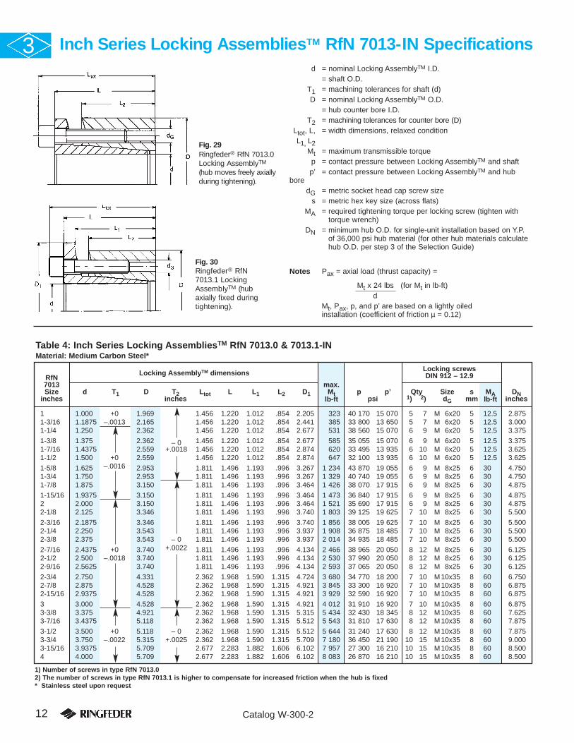
1 1.000 +0 1.969 1.456 1.220 1.012 .854 2.205 323 40 170 15 070 5 7 M 6x20 5 12.5 2.8751-3/16 1.1875 –.0013 2.165 1.456 1.220 1.012 .854 2.441 385 33 800 13 650 5 7 M 6x20 5 12.5 3.0001-1/4 1.250 2.362 1.456 1.220 1.012 .854 2.677 531 38 560 15 070 6 9 M 6x20 5 12.5 3.375
1-3/8 1.375 2.362 – 0 1.456 1.220 1.012 .854 2.677 585 35 055 15 070 6 9 M 6x20 5 12.5 3.3751-7/16 1.4375 2.559 +.0018 1.456 1.220 1.012 .854 2.874 620 33 495 13 935 6 10 M 6x20 5 12.5 3.6251-1/2 1.500 +0 2.559 1.456 1.220 1.012 .854 2.874 647 32 100 13 935 6 10 M 6x20 5 12.5 3.625
1-5/8 1.625 –.0016 2.953 1.811 1.496 1.193 .996 3.267 1 234 43 870 19 055 6 9 M 8x25 6 30 4.7501-3/4 1.750 2.953 1.811 1.496 1.193 .996 3.267 1 329 40 740 19 055 6 9 M 8x25 6 30 4.7501-7/8 1.875 3.150 1.811 1.496 1.193 .996 3.464 1 426 38 070 17 915 6 9 M 8x25 6 30 4.875
1-15/16 1.9375 3.150 1.811 1.496 1.193 .996 3.464 1 473 36 840 17 915 6 9 M 8x25 6 30 4.8752 2.000 3.150 1.811 1.496 1.193 .996 3.464 1 521 35 690 17 915 6 9 M 8x25 6 30 4.8752-1/8 2.125 3.346 1.811 1.496 1.193 .996 3.740 1 803 39 125 19 625 7 10 M 8x25 6 30 5.500
2-3/16 2.1875 3.346 1.811 1.496 1.193 .996 3.740 1 856 38 005 19 625 7 10 M 8x25 6 30 5.5002-1/4 2.250 3.543 1.811 1.496 1.193 .996 3.937 1 908 36 875 18 485 7 10 M 8x25 6 30 5.5002-3/8 2.375 3.543 – 0 1.811 1.496 1.193 .996 3.937 2 014 34 935 18 485 7 10 M 8x25 6 30 5.500
2-7/16 2.4375 +0 3.740 +.0022 1.811 1.496 1.193 .996 4.134 2 466 38 965 20 050 8 12 M 8x25 6 30 6.1252-1/2 2.500 –.0018 3.740 1.811 1.496 1.193 .996 4.134 2 530 37 990 20 050 8 12 M 8x25 6 30 6.1252-9/16 2.5625 3.740 1.811 1.496 1.193 .996 4.134 2 593 37 065 20 050 8 12 M 8x25 6 30 6.125
2-3/4 2.750 4.331 2.362 1.968 1.590 1.315 4.724 3 680 34 770 18 200 7 10 M 10x35 8 60 6.7502-7/8 2.875 4.528 2.362 1.968 1.590 1.315 4.921 3 845 33 300 16 920 7 10 M 10x35 8 60 6.8752-15/16 2.9375 4.528 2.362 1.968 1.590 1.315 4.921 3 929 32 590 16 920 7 10 M 10x35 8 60 6.875
3 3.000 4.528 2.362 1.968 1.590 1.315 4.921 4 012 31 910 16 920 7 10 M 10x35 8 60 6.8753-3/8 3.375 4.921 2.362 1.968 1.590 1.315 5.315 5 434 32 430 18 345 8 12 M 10x35 8 60 7.6253-7/16 3.4375 5.118 2.362 1.968 1.590 1.315 5.512 5 543 31 810 17 630 8 12 M 10x35 8 60 7.875
3-1/2 3.500 +0 5.118 – 0 2.362 1.968 1.590 1.315 5.512 5 644 31 240 17 630 8 12 M 10x35 8 60 7.8753-3/4 3.750 –.0022 5.315 +.0025 2.362 1.968 1.590 1.315 5.709 7 180 36 450 21 190 10 15 M 10x35 8 60 9.0003-15/16 3.9375 5.709 2.677 2.283 1.882 1.606 6.102 7 957 27 300 16 210 10 15 M 10x35 8 60 8.5004 4.000 5.709 2.677 2.283 1.882 1.606 6.102 8 083 26 870 16 210 10 15 M 10x35 8 60 8.500
12 Catalog W-300-2
Inch Series Locking AssembliesTM RfN 7013-IN Specifications3
Fig. 29Ringfeder® RfN 7013.0Locking AssemblyTM
(hub moves freely axiallyduring tightening).
Fig. 30Ringfeder® RfN7013.1 LockingAssemblyTM (hubaxially fixed duringtightening).
d = nominal Locking AssemblyTM I.D.= shaft O.D.
T1 = machining tolerances for shaft (d)D = nominal Locking AssemblyTM O.D.
= hub counter bore I.D.T2 = machining tolerances for counter bore (D)
Ltot, L, = width dimensions, relaxed conditionL1, L2
Mt = maximum transmissible torquep = contact pressure between Locking AssemblyTM and shaftp’ = contact pressure between Locking AssemblyTM and hub
boredG = metric socket head cap screw size
s = metric hex key size (across flats)MA = required tightening torque per locking screw (tighten with
torque wrench)DN = minimum hub O.D. for single-unit installation based on Y.P.
of 36,000 psi hub material (for other hub materials calculatehub O.D. per step 3 of the Selection Guide)
Notes Pax = axial load (thrust capacity) =
Mt x 24 lbs (for Mt in lb-ft) d
Mt, Pax, p, and p’ are based on a lightly oiled installation (coefficient of friction µ = 0.12)
Locking screwsRfN
Locking AssemblyTM dimensions DIN 912 – 12.97013 max.Size d T1 D T2 Ltot L L1 L2 D1 Mt p p’ Qty Size s MA DN
inches inches lb-ft psi 1) 2) dG mm lb-ft inches
Table 4: Inch Series Locking AssembliesTM RfN 7013.0 & 7013.1-INMaterial: Medium Carbon Steel*
1) Number of screws in type RfN 7013.02) The number of screws in type RfN 7013.1 is higher to compensate for increased friction when the hub is fixed* Stainless steel upon request

20x 47 .787 1.850 1.456 1.220 1.012 .854 2.086 217 40 810 12 800 4 6 M 6x20 5 12.5 2.62522x 47 .866 1.850 – 0 1.456 1.220 1.012 .854 2.086 238 36 975 12 800 4 6 M 6x20 5 12.5 2.62524x 50 .945 +0 1.969 +.0016 1.456 1.220 1.012 .854 2.205 303 42 520 15 070 5 7 M 6x20 5 12.5 2.875
25x 50 .984 –.0013 1.969 1.456 1.220 1.012 .854 2.205 318 40 810 15 070 5 7 M 6x20 5 12.5 2.87528x 55 1.102 2.165 1.456 1.220 1.012 .854 2.441 354 36 405 13 650 5 7 M 6x20 5 12.5 3.00030x 55 1.181 2.165 1.456 1.220 1.012 .854 2.441 383 33 985 13 650 5 7 M 6x20 5 12.5 3.000
32x 60 1.260 2.362 1.456 1.220 1.012 .854 2.667 535 38 250 15 070 6 9 M 6x20 5 12.5 3.37535x 60 1.378 2.362 1.456 1.220 1.012 .854 2.667 585 34 980 15 070 6 9 M 6x20 5 12.5 3.37538x 65 1.496 2.559 – 0 1.456 1.220 1.012 .854 2.874 640 32 130 13 935 6 10 M 6x20 5 12.5 3.625
40x 65 1.575 +0 2.559 +.0018 1.456 1.220 1.012 .854 2.874 680 30 575 13 935 6 10 M 6x20 5 12.5 3.62542x 75 1.654 –.0016 2.953 1.811 1.496 1.193 .996 3.267 1 250 43 085 19 055 6 9 M 8x25 6 30 4.75045x 75 1.772 2.953 1.811 1.496 1.193 .996 3.267 1 345 40 245 19 055 6 9 M 8x25 6 30 4.750
48x 80 1.890 3.150 1.811 1.496 1.193 .996 3.464 1 430 37 825 17 915 6 9 M 8x25 6 30 4.87550x 80 1.969 3.150 1.811 1.496 1.193 .996 3.464 1 497 36 260 17 915 6 9 M 8x25 6 30 4.87555x 85 2.165 3.346 1.811 1.496 1.193 .996 3.740 1 837 38 395 19 625 7 10 M 8x25 6 30 5.50060x 90 2.362 3.543 1.811 1.496 1.193 .996 3.937 2 003 35 125 18 485 7 10 M 8x25 6 30 5.500
65x 95 2.559 +0 3.740 – 0 1.811 1.496 1.193 .996 4.134 2 589 37 115 20 050 8 12 M 8x25 6 30 6.12570x110 2.756 –.0018 4.331 +.0022 2.362 1.968 1.590 1.315 4.724 3 688 34 700 18 200 7 10 M 10x35 8 60 6.75075x115 2.953 4.528 2.362 1.968 1.590 1.315 4.921 3 949 32 425 16 920 7 10 M 10x35 8 60 6.875
80x120 3.150 4.724 2.362 1.968 1.590 1.315 5.118 4 231 30 430 15 925 7 10 M 10x35 8 60 6.93785x125 3.346 4.921 2.362 1.968 1.590 1.315 5.315 5 388 32 710 18 345 8 12 M 10x35 8 60 7.62590x130 3.543 5.118 2.362 1.968 1.590 1.315 5.512 5 714 30 860 17 630 8 12 M 10x35 8 60 7.875
95x135 3.740 +0 5.315 – 0 2.362 1.968 1.590 1.315 5.709 7 160 36 545 21 190 10 15 M 10x35 8 60 9.000100x145 3.937 –.0022 5.709 +.0025 2.677 2.283 1.882 1.606 6.102 7 956 27 300 16 210 10 15 M 10x35 8 60 8.500110x155 4.331 6.102 2.677 2.283 1.882 1.606 6.496 8 751 24 885 15 215 10 15 M 10x35 8 60 8.750
120x165 4.724 6.496 2.677 2.283 1.882 1.606 6.890 11 355 27 300 17 065 12 18 M 10x35 8 60 9.875130x180 5.118 7.087 3.031 2.560 2.063 1.787 7.480 14 972 26 735 17 065 10 15 M 12x40 10 105 10.625140x190 5.512 +0 7.480 – 0 3.031 2.560 2.063 1.787 7.874 16 274 24 885 16 210 10 15 M 12x40 10 105 11.250150x200 5.906 –.0025 7.874 +.0028 3.031 2.560 2.063 1.787 8.267 20 614 27 875 18 485 12 18 M 12x40 10 105 12.375
13Catalog W-300-2
Metric RfN 7013 Specifications 3
Locking screwsRfN
Locking AssemblyTM dimensions DIN 912 – 12.97013 max.Size d T1 D T2 Ltot L L1 L2 D1 Mt p p’ Qty Size s MA DNmm inches lb-ft psi 1) 2) dG mm lb-ft inches
Table 5: Metric Series Locking AssembliesTM RfN 7013.0 & 7013.1Material: Medium Carbon Steel*
1) Number of screws in type RfN 7013.02) The number of screws in type RfN 7013.1 is higher to compensate for increased friction when the hub is fixed* Stainless steel upon request
Since the torque is transmitted by contact pressure and fric-tion between the frictional surfaces, the condition of the con-tact surfaces and the proper tightening of the locking screwsare important.INSTALLATION1. Verify that all contact surfaces, including the screw
threads and screw head bearing surfaces, are clean andlightly oiled.Note: Do NOT use Molybdenum Disulfide, “Molykote” orany other similar lubricants.
2. Slide the Locking AssemblyTM onto the shaft and intothe hub bore, aligning them as required.
3. Tighten the locking screws gradually in a diametricallyopposite sequence as follows:a) Hand-tighten 3 or 4 equally spaced locking screws
until they make contact. Align and adjust the con-nection.
b) Hand-tighten and take up all remaining lockingscrews.
c) Use a torque wrench to tighten the screws further toapproximately one-half the specified torque (MA).
d) Using the torque wrench tighten the screws to fulltightening torque (MA).
e) Verify that the screws are completely tight by apply-ing the specified tightening torque (MA).
REMOVAL1. Loosen all screws several turns.2. Remove the screw adjacent to each threaded jacking
hole and screw it into its corresponding jacking hole topress off the outer ring. This releases the connection.
3. Remove the hub and the Locking AssemblyTMfrom theshaft. Leave the screws in the jacking holes until youhave completely removed the Locking AssemblyTM fromthe hub.Disassemble and clean dirty undamaged LockingAssembliesTM before re-use.
TOOLS REQUIRED FOR ASSEMBLY AND REMOVALa) Standard torque wrench with either 1/4” or 3/8” square
drive and suitable torque range; see Table for specifiedtightening torques (MA).
b) Metric hexagonal bit socket (see Fig. 31: Square Drives)for torque wrench with suitable across flats dim. (s); seeTable 3.
NOTE: DO NOT USE IMPACT WRENCH!
Installation and Removal Instructions
Fig. 31: Square Drives1/4” or 3/8” square drive

14 Catalog W-300-2
4 Ringfeder®
Shrink Discs®
RfN 4071, RfN 4091 & RfN 4051
Shrink Discs® are used to transmit high torques, particularly whenexternal clamping is advantageous and a high degree of concen-tricity is required. Ringfeder® Shrink Discs® are self-contained andready for installation over a hub projection.
Applications Examples
Fig. 32: Apron Feeder DriveApron feeder drive; hydraulic power unit, RidleyIsland Coal Terminal.
Fig. 35: Speed ReducerShaft-mounted speed reducer fastened with aShrink Disc®.
Fig. 36: Shrink Disc®
RING-flex® torsionally rigid, backlash-free couplingsuse Ringfeder® Shrink Discs® to give a truly back-lash-free shaft to shaft coupling.
Fig. 33: GearGear mounted with a Shrink Disc®
on a straight side press.
Fig. 34: ClutchClutch of a 2,500 ton press shaft mountedwith a Shrink Disc®.
RINGFEDER Products are available from MARYLAND METRICSP.O. Box 261 Owings Mills, MD 21117 USA email: [email protected] web: http://mdmetric.com
phones: (410)358-3130 (800)638-1830 faxes: (410)358-3142 (800)872-9329

15Catalog W-300-2
4
Fig. 37: RING-flex® coupling in automotiveplant main conveyor drive.
Fig. 38: Shrink Disc® on engine flywheel couplingfor diesel driven compressor.
Fig. 41: Shrink Disc® on bull gear of punch press.
Fig. 39: Shrink Disc® on U-joint drive in sawmillequipment.
Fig. 40: Diesel engine flywheel coupling.
Fig. 43: Stepped Sleeve CouplingRigid Shrink Disc® stepped sleeve coupling.
Fig. 42: Rigid Flange Coupling
16 Catalog W-300-2
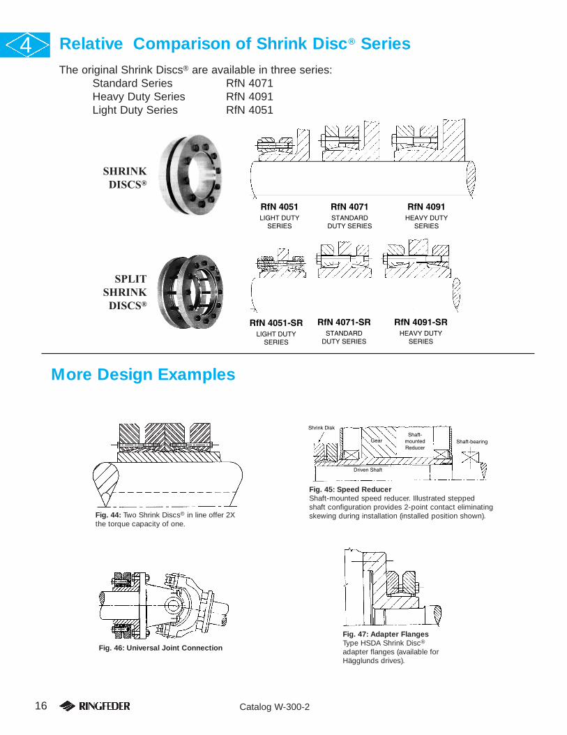
Relative Comparison of Shrink Disc® Series4
Shrink Disk
GearShaft-
mounted Reducer
Shaft-bearing
Driven Shaft
FiguType
Fig. 45: Speed ReducerShaft-mounted speed reducer. Illustrated steppedshaft configuration provides 2-point contact eliminatingskewing during installation (installed position shown).
Fig. 47: Adapter FlangesType HSDA Shrink Disc®
adapter flanges (available forHägglunds drives).
Fig. 46: Universal Joint Connection
More Design Examples
SHRINKDISCS®
RfN 4051LIGHT DUTY
SERIES
RfN 4091HEAVY DUTY
SERIES
RfN 4071STANDARD
DUTY SERIES
SPLITSHRINK
DISCS®
RfN 4051-SRLIGHT DUTY
SERIES
RfN 4091-SRHEAVY DUTY
SERIES
RfN 4071-SRSTANDARD
DUTY SERIES
The original Shrink Discs® are available in three series:Standard Series RfN 4071Heavy Duty Series RfN 4091Light Duty Series RfN 4051
Fig. 44: Two Shrink Discs® in line offer 2Xthe torque capacity of one.

17Catalog W-300-2
General Engineering Information 4
The Maximum Transmissible Torque is a function of the shaftdiameter, the coefficient of friction (µ) and the clearancebetween the shaft and hub. Torque is calculated using theequation:
Mt = P x π x dW
2x l x µ
24
P = contact pressure between shaft and hub (psi)dW = shaft diameter (inches)I = inner ring length (inches)
Coefficient of friction (µ) can vary widely depending on materialand surface finish. A well-accepted number for interference fitsthat are lightly oiled is µ=0.12. This fig. is used to determinetorque capacity listed in this catalog. If shaft and hub areassembled dry, µ=0.15 can be assumed. Tests have shown thatgrease-free connections can attain coefficients greater than 0.2.The transmissible torque is then increased proportionately.
Hub stress calculation, which determine the material require-ments for the hub, are based on multi-directional stresses. Thefollowing equation uses the “maximum distortion energy theo-ry” to calculate the maximum combined stress in the hub.
�VH = √ 1/2 {(�XH-�YH)2 + (�YH-�ZH)2 + (�ZH-�XH)2} + 3�H2
where:�VH = combined stress (psi)�XH = tangential stress (psi)�YH = radial stress (psi)�ZH = axial and bending stress (psi)�H = torsional shear stress (psi)
Individual stress components can be determined by using the Laméthick wall cylinder equations. (See Fig. 48).
Fit clearances can also affect torque capacity. Catalog valuesare calculated using maximum fit clearance. See subsequentdata tables for suggested tolerance allowances. These fits willallow easy assembly and disassembly.
If larger clearances are required, torque will be reduced propor-tionately. Also, hub stresses will increase and could exceed theyield strength of the material, causing plastic deformation.Please contact us if larger fit clearances are required.
Allowable hub O.D. tolerances and maximum radius allowedadjacent to the Shrink Disc® are given in subsequent datatables. Materials with a minimum yield point of 50,000 psi arerecommended. Because the hub is in compression, grey castirons are suitable. Other materials can be used if combinedstresses are kept below the yield point of the material. Contactour engineering department for a complete stress analysis.
Hollow shafts do not act the same as solid shafts under compressiveradial loads. Depending on the wall thickness there will be varyingamounts of elastic deformation and consequently a reduction in torquecapacity. Our engineering department can provide complete informa-tion based on your requirements.
If combined torsional and axial loads are to be transmitted,calculate the torque as follows:
Mt res = Mt2 + (Pax x d) 2
≤ Mt cat24
Mt res = resultant torque to be transmitted (lb-ft)
Mt = actual or maximum torque to be transmitted (lb-ft)
Pax = axial load-thrust to be transmitted (lbs)
dW = shaft diameter (inches)
Mt cat = max. transmissible torque (lb-ft) of Shrink DiscTM
as specified in catalog
The required surface finish for both shaft and hub projection I.D. and O.D. is RMS 125 microinches or better.
Fig. 48
√

18 Catalog W-300-2
Selection Guide4
Shrink Discs® RfN 4071 Specifications
Shrink Discs®
1 Determine the shaft diameter (dw) to be used orthe maximum torque (Mt) to be transmitted.Note: For hollow shaft applications, consultRingfeder Corporation.
2 Select a Shrink Disc® from the Table for requiredshaft dia. (dw) and verify that the correspondingmaximum transmissible torque (Mt) meets thetorque requirement.
If torque is the primary requirement, select thenecessary torque (Mt) from the same specificationtable and determine the corresponding shaftdiameter (dw).
3 Incorporate the specified dimensions of theselected Shrink Disc® and required hub into yourdesign and drawing. Indicate the specified tight-ening torque (MA) for each locking screw on the drawing.
4 Establish machining tolerances (TH, TW) for shaft,hub bore and hub outer diameter from the specifi-cation tables.
Ordering ExampleSize RfN Series
Example: 90 RfN 4071
d = nominal Shrink DiscTM I.D.= hub projection O.D.
TH = specified tolerance for hub O.D. (d)dW = shaft size range (min.- max.)TW = total allowable diametrical clearance between shaft
and hub bore (dW)Mt = maximum transmissible torqueD = Shrink DiscTM O.D.d1 = bolt circle dia.d2 = thrust ring I.D.
L, L1,L2, e = width dimensions, relaxed conditions = head dimension across flats (mm)MA = required tightening torque per locking screwd3 = 0.98 x d (for option 1)r = customer selectable (for option 2)
Pax = Mt x 24 lbs (for option 2)dW
See Detail A and Options
Allow space for torque wrench
Option 1 Option 2
Fig. 49: Shrink Disc® LayoutShrink Disc® RfN 4071
Detail A
Notes 1 Tapers and screws lubricated with Molykote GnPaste or equivalent.
2 For Series RfN 4071:Sizes 24 to 200 have a thru-drilled tapped hole.All larger sizes have a blind tapped hole.

19Catalog W-300-2
Shrink Discs® RfN 4071 Specifications, continued 4
24 .945 +0.625 077 1.97 1.417 1.024 .551 .768 .906 .315 .108 .4 6 M 5x 18 8
–.0013.827 184
30 1.181 .875 .0007 160 2.36 1.732 1.260 .630 .846 .984 .354 .108 .7 7 M 5x 18 81.024 273
36 1.417 1.062 .065 295 2.83 2.047 1.496 .709 .925 1.083 .394 .108 .9 5 M 6x 20 101.220 465
44 1.732 +0 1.250 438 3.15 2.402 1.850 .787 1.004 1.161 .433 .108 1.3 7 M 6x 20 10–.0015 1.437 660
50 1.969 1.496 693 3.54 2.756 2.087 .866 1.083 1.240 .472 .108 1.8 8 M 6x 25 101.654 1 018
55 2.165 1.654 .0013 856 3.94 2.953 2.283 .906 1.201 1.358 .512 .148 2.4 8 M 6x 25 101.890 1 387
62 2.441 1.890 1 365 4.33 3.386 2.598 .906 1.201 1.358 .512 .148 2.9 10 M 6x 25 102.047 1 770
68 2.677+0 1.969 1 475 4.53 3.386 2.835 .906 1.201 1.358 .512 .148 3.1 10 M 6x 25 10–.0018 2.362 .105 2 323
75 2.953 2.165 1 844 5.43 3.937 3.110 .984 1.280 1.496 .551 .148 3.7 7 M 8x 30 132.559 2 914
80 3.150 2.362.0019
2 360 5.71 3.937 3.307 .984 1.280 1.496 .551 .148 4.2 7 M 8x 30 132.756 3 393
90 3.543 2.559 .145 3 504 6.10 4.488 3.701 1.181 1.535 1.752 .669 .177 7.3 10 M 8x 35 13+0
2.953 5 348
100 3.937 –.00212.756 .165 5 089 6.69 4.882 4.094 1.339 1.732 1.949 .748 .197 10.4 12 M 8x 35 133.150 6 638
110 4.331 2.953 .185 5 311 7.28 5.354 4.488 1.535 1.969 2.244 .866 .217 13.0 9 M 10x 40 173.346 7 966
125 4.921 3.346 .205 8 114 8.46 6.299 5.276 1.654 2.126 2.402 .906 .236 18.3 12 M 10x 40 173.740 11 064
140 5.512 3.740 11 138 9.06 6.890 5.748 1.811 2.382 2.697 1.024 .285 22.0 10 M 12x 45 194.134 .0027 14 826
155 6.102+0 4.134 16 227 10.43 7.559 6.496 1.969 2.539 2.854 1.102 .285 33.1 12 M 12x 50 19–.0025 4.528 .225 20 653
165 6.496 4.528 22 866 11.42 8.268 6.890 2.205 2.795 3.189 1.220 .295 48.5 8 M 16x 55 244.921 28 766
175 6.890 4.921 26 554 11.81 8.661 7.283 2.205 2.795 3.198 1.220 .295 48.5 8 M 16x 55 245.315 33 192
185 7.283 5.315 38 355 12.99 9.291 7.677 2.795 3.386 3.780 1.496 .295 81.6 10 M 16x 65 245.709 45 731
195 7.677 5.512.0031 .265 47 944 13.78 9.685 8.268 2.795 3.386 3.780 1.496 .295 90.4 12 M 16x 65 24
+06.102 60 114
200 7.874 –.00285.906 54 582 13.78 9.685 8.268 2.795 3.386 3.780 1.496 .295 90.4 12 M 16x 65 246.299 63 434
220 8.661 6.299 70 072 14.57 10.630 9.055 3.465 4.094 4.488 1.850 .315 119.0 15 M 16x 80 246.693 .285 81 136
240 9.449 6.693 88 512 15.94 11.614 9.764 3.622 4.291 4.803 1.929 .335 147.7 12 M 20x 80 307.480 115 066
260 10.236 7.480 .305 120 966 16.93 12.638 10.551 4.055 4.724 5.236 2.126 .335 180.8 14 M 20x 90 308.268 151 208
280 11.024+0 8.268 160 059 18.11 13.622 11.339 4.488 5.276 5.787 2.362 .394 224.9 16 M 20x100 30–.0032 9.055 .0035 199 152
300 11.811 9.055 202 840 19.09 14.331 12.126 4.803 5.591 6.102 2.520 .394 260.1 18 M 20x100 309.646 .340 232 344
320 12.598 9.449 230 131 20.47 15.197 12.913 4.803 5.591 6.102 2.520 .394 288.8 20 M 20x100 3010.236 275 862
340 13.386 9.843 .400 287 664 22.44 16.063 13.701 5.276 6.142 6.654 2.795 .433 410.1 24 M 20x110 3010.630 339 296
350 13.780 10.630 326 019 22.83 17.008 14.094 5.512 6.378 6.890 2.874 .433 429.9 24 M 20x110 3011.220 368 800
360 14.173+0 11.024 .0040 341 509 23.23 17.008 14.488 5.512 6.378 6.890 2.874 .433 449.7 24 M 20x110 30–.0035 11.614 385 027
380 14.961 11.417 .360 418 219 25.39 18.031 15.236 5.669 6.614 7.205 2.992 .472 526.9 20 M 24x120 3612.205 485 341
390 15.354 11.811 460 262 25.98 18.425 15.630 5.669 6.614 7.205 2.992 .472 573.2 21 M 24x120 3612.598 529 597
400 15.748 12.402 494 192 26.77 18.898 16.024 5.669 6.614 7.205 2.992 .472 617.3 21 M 24x120 3612.992 548 774
420 16.535 12.992 575 328 27.17 19.843 16.811 6.457 7.402 7.992 3.386 .472 696.7 24 M 24x130 3613.780 663 840
440 17.323 13.386 .0044 594 506 29.53 20.748 17.598 6.969 7.953 8.543 3.583 .492 899.5 24 M 24x140 3614.173 .380 676 379
460 18.110 +0 14.173 737 600 30.31 21.535 18.425 6.969 7.953 8.543 3.583 .492 925.9 28 M 24x140 36–.0038 14.961 840 864
480 18.898 14.961 862 992 31.50 22.441 19.213 7.402 8.386 8.976 3.780 .492 1113.3 30 M 24x140 3615.748 966 256
500 19.685 15.748 .0048.480 967 731 33.46 23.228 20.000 7.402 8.386 9.055 3.780 .492 1267.6 24 M 27x150 4116.535 1073 208
MAlb-ft
3
3
9
9
9
9
9
9
22
22
22
22
44
44
74
74
185
185
185
185
185
185
362
362
362
362
362
362
362
362
620
620
620
620
620
620
620
922
Locking screwsShaft/Hub dimensions Shrink Disc® dimensions DIN 931 - 10.9
RfN max.4071 d TH dW TW R1max. Mt D d1 d2 I L L1 L2 e Wt. Qty Size sSize inches lb-ft inches lbs mm
Table 6: Shrink Disc® Series RfN 4071Material: Alloy Steel*
* Stainless steel available upon request.Additional information is available for Heavy Duty Series RfN 4091 and Light Duty Series RfN 4051.

20 Catalog W-300-2
Light Duty Shrink Discs® RfN 4051 Specifications4
Option 2
d = nominal Shrink Disc® I.D.= hub projection O.D.
TH = specified tolerance for hub O.D. (d)dW = shaft size range (min.- max.)TW = total allowable diametrical clearance between shaft
and hub bore (dW)Mt = maximum transmissible torqueD = Shrink Disc® O.D.d1 = bolt circle dia.d2 = thrust ring I.D.L, L1,L2, e = width dimensions, relaxed conditionPax = axial load (thrust capacity)
= Mt x 24 lbs (for Mt in lb-ft)d
s = head dimension across flats (mm)MA = required tightening torque per locking screwd3 = 0.98 x d (for Option 1)r = to be selected by customer (for Option 2)
Notes1. Tapers and screws lubricated with Molykote Gn Paste or
equivalent.2. For Series RfN 4051:
Sizes 125 to 260 have a thru-drilled tapped hole.All larger sizes have a blind tapped hole.
See Detail A and Options
Allow space for torque wrench
Fig. 50: Shrink Disc®
Detail A
Option 1
Table 7: Light Duty Shrink Disc® RfN 4051Material: Alloy Steel*
* Stainless steel available upon request.
MAlb-ft
44
44
44
74
74
74
74
74
185
185
185
185
185
185
185
362
362
362
362
362
362
362
362
362
362
Locking screwsShaft/Hub dimensions Shrink Disc® dimensions DIN 931 - 10.9
RfN max.4051 d TH dW TW R1max. Mt D d1 d2 I L L1 L2 e Wt. Qty Size sSize inches lb-ft inches lbs mm
125 4.921 3.740 7 782 7.28 6.220 5.079 1.535 2.008 2.283 .866 .236 13.2 8 M 10x 40 174.134 .0027 10 179
140 5.512 4.331 .225 10 916 8.66 6.890 5.669 1.535 2.008 2.283 .866 .236 17.6 9 M 10x 40 17+0 4.921 15 121
155 6.102 –.0025 5.118 17 702 9.65 7.559 6.260 1.535 2.008 2.283 .866 .236 22.0 11 M 10x 40 175.512 21 390
165 6.496 5.315 23 603 10.24 8.268 6.654 1.811 2.441 2.756 1.024 .315 30.9 10 M 12x 50 195.709 28 398
175 6.890 5.709 28 766 10.83 8.661 7.047 1.811 2.441 2.756 1.024 .315 35.3 11 M 12x 50 196.102 33 930
185 7.283 6.102 .0031.300 34 372 11.61 8.858 7.441 1.811 2.441 2.756 1.024 .315 44.1 12 M 12x 50 196.496 39 830
195 7.677 6.496 46 469 12.40 9.331 7.835 2.205 2.835 3.150 1.220 .315 59.5 15 M 12x 55 196.890 53 476
200 7.874+0 6.890 54 582 12.99 9.528 8.031 2.205 2.835 3.150 1.220 .315 66.1 16 M 12x 55 19–.0028 7.283 62 327
220 8.661 7.087 61 073 13.58 10.433 8.819 2.598 3.307 3.701 1.417 .354 77.2 10 M 16x 65 247.874 77 448
240 9.449 7.874.0035
.340 83 349 14.57 11.417 9.606 2.598 3.307 3.701 1.417 .354 97.0 12 M 16x 65 248.465 99 207
260 10.236 8.661 109 902 15.55 12.205 10.433 2.835 3.622 4.016 1.575 .354 105.8 14 M 16x 70 24+0
9.252 127 605
280 11.024 –.00329.055 126 130 16.73 13.110 11.220 3.307 4.094 4.488 1.811 .394 132.3 16 M 16x 75 249.843 .380 153 421
300 11.811 9.843 158 584 18.11 14.094 12.008 3.307 4.094 4.488 1.811 .394 165.3 18 M 16x 75 2410.630 188 088
320 12.598 10.630 191 776 19.49 14.882 12.795 3.307 4.173 4.567 1.890 .433 185.2 20 M 16x 75 2411.417 225 706
340 13.386 11.417 .0040 221 280 21.06 15.827 13.583 3.307 4.173 4.567 1.890 .433 220.5 21 M 16x 75 2412.008 248 571
350 13.780 11.811 .420 274 387 21.46 16.260 13.976 3.937 4.803 5.315 2.126 .433 264.6 16 M 20x 90 3012.205 295 040
360 14.173+0 11.811 265 536 21.85 16.654 14.370 3.937 4.803 5.315 2.126 .433 275.6 16 M 20x 90 30–.0035 12.598 306 104
380 14.961 12.598 320 856 23.03 17.402 15.236 4.409 5.354 5.866 2.362 .472 330.7 18 M 20x100 3012.992 344 459
390 15.354 12.992 372 488 23.43 17.795 15.630 4.409 5.354 5.866 2.362 .472 343.9 20 M 20x100 3013.780 425 595
400 15.748 13.386.0044
405 680 24.21 18.189 16.024 4.409 5.354 5.866 2.362 .472 374.8 21 M 20x100 3014.173 .460 461 738
420 16.535 13.780 426 333 24.80 19.094 16.811 4.724 5.669 6.181 2.520 .472 407.9 22 M 20x100 3014.567 483 128
440 17.323 14.567 499 355 25.98 19.882 17.598 4.724 5.669 6.181 2.520 .472 451.9 24 M 20x100 30+0
15.354 562 051
460 18.110 –.003815.354 619 584 26.97 20.748 18.425 5.197 6.220 6.732 2.795 .512 518.1 28 M 20x110 3016.142 689 656
480 18.898 16.142 .500 657 202 28.15 21.535 19.213 5.197 6.220 6.732 2.795 .512 562.2 28 M 20x110 3016.732 .0048 712 522
500 19.685 16.732 727 274 29.53 22.323 20.000 5.197 6.220 6.732 2.795 .512 628.3 30 M 20x110 3017.323 786 282

21Catalog W-300-2
Heavy Duty Shrink Discs® RfN 4091 Specifications 4
Table 8: Heavy Duty Shrink Disc® RfN 4091Material: Alloy Steel*
* Stainless steel available upon request.
125 4.921 3.346 11 064 8.46 6.299 5.079 2.165 2.559 2.874 1.102 .197 24.3 10 M 12x 50 193.740 14 752
140 5.512 3.740 .265 15 195 9.06 6.890 5.669 2.362 2.913 3.228 1.260 .276 28.7 12 M 12x 55 19+0 4.134 .0027 19 546
155 6.102 –.0025 4.134 21 095 10.43 7.795 6.457 2.598 3.150 3.465 1.378 .276 44.1 15 M 12x 60 194.528 26 849
165 6.496 4.528 30 242 11.42 8.268 6.850 2.835 3.465 3.858 1.496 .315 57.3 10 M 16x 65 244.921 .300 37 396
175 6.890 4.921 34 667 11.81 8.661 7.244 2.835 3.465 3.858 1.496 .315 63.9 10 M 16x 65 245.315 42 043
185 7.283 5.315 53 107 12.99 9.291 7.638 3.622 4.409 4.803 1.969 .394 103.6 14 M 16x 80 245.709 63 434
195 7.677 5.512.0031
55 320 13.78 9.685 7.835 3.622 4.409 4.803 1.969 .394 116.8 14 M 16x 80 246.102 .380 70 810
200 7.874+0 5.709 62 696 13.78 9.685 8.031 3.622 4.409 4.803 1.969 .394 110.2 15 M 16x 80 24–.0028 6.102 73 760
220 8.661 6.299 93 675 14.57 10.630 8.819 4.488 5.276 5.669 2.362 .394 143.3 20 M 16x 90 246.693 108 058
240 9.449 6.693 114 328 15.94 11.614 9.606 4.724 5.669 6.181 2.559 .472 191.8 15 M 20x100 307.480 146 045
260 10.236 7.480 157 109 16.93 12.638 10.433 5.354 6.299 6.811 2.835 .472 220.5 18 M 20x110 30+0
8.268 197 677
280 11.024 –.00328.268 210 216 18.11 13.622 11.220 5.827 6.772 7.283 3.071 .472 291.0 21 M 20x120 309.055 .0035 261 848
300 11.811 9.055 251 522 19.09 14.331 12.008 5.984 6.929 7.441 3.150 .472 308.6 22 M 20x120 309.646 290 614
320 12.598 9.449 278 813 20.47 15.197 12.795 6.299 7.244 7.756 3.228 .472 363.8 24 M 20x130 3010.236 332 658
340 13.386 9.843 361 055 22.44 16.535 13.583 6.929 7.874 8.465 3.622 .472 529.1 21 M 24x130 3610.630 426 333
350 13.780 10.630 .460 410 106 22.83 16.732 13.976 6.929 7.874 8.465 3.622 .472 544.5 21 M 24x130 3611.220 463 950
360 14.173+0 11.024 .0040 451 411 23.23 17.008 14.370 7.087 8.031 8.622 3.622 .472 551.1 22 M 24x140 36–.0035 11.614 508 206
380 14.961 11.417 455 837 25.39 18.031 15.236 7.087 8.031 8.622 3.622 .472 705.5 22 M 24x140 3612.205 530 334
390 15.354 11.811 522 221 25.98 18.425 15.630 7.402 8.346 8.937 3.780 .472 771.6 24 M 24x140 3612.598 600 775
400 15.748 12.402 564 264 26.77 18.898 16.024 7.402 8.346 8.937 3.780 .472 815.7 24 M 24x140 3612.992 623 272
420 16.535 12.992 736 862 27.17 19.843 16.811 8.425 9.370 9.961 4.370 .472 903.9 30 M 24x150 3613.780 840 864
440 17.323 13.386 .0044 780 381 29.53 20.748 17.638 8.819 9.921 10.591 4.528 .551 1190.5 24 M 27x170 41+0
14.173 888 070
460 18.110 –.003814.173 973 632 30.31 21.535 18.425 8.819 9.921 10.591 4.528 .551 1190.5 28 M 27x170 4114.961 1106 400
480 18.898 14.961 .540 1132 216 31.50 22.835 19.213 9.685 10.787 11.457 5.039 .551 1433.0 30 M 27x180 4115.748 1 268 672
500 19.685 15.748 1 290 800 33.46 23.622 20.000 9.685 10.787 11.457 5.039 .551 1653.5 32 M 27x180 4116.535 .0048 1 430 944
MAlb-ft
74
74
74
185
185
185
185
185
185
362
362
362
362
362
620
620
620
620
620
620
620
922
922
922
92
Locking screwsShaft/Hub dimensions Shrink Disc® dimensions DIN 931 - 10.9
RfN max.4091 d TH dW TW R1max. Mt D d1 d2 I L L1 L2 e Wt. Qty Size sSize inches lb-ft inches lbs mm
Option 2
d = nominal Shrink Disc® I.D.= hub projection O.D.
TH = specified tolerance for hub O.D. (d)dW = shaft size range (min.- max.)TW = total allowable diametrical clearance between shaft
and hub bore (dW)Mt = maximum transmissible torqueD = Shrink Disc® O.D.d1 = bolt circle dia.d2 = thrust ring I.D.L, L1, L2, e = width dimensions, relaxed conditionPax = axial load (thrust capacity)
= Mt x 24 lbs (for Mt in lb-ft)d
s = head dimension across flats (mm)MA = required tightening torque per locking screwd3 = 0.98 x d (for Option 1)r = to be selected by customer (for Option 2)
Notes1. Tapers and screws lubricated with Molykote Gn Paste or
equivalent.2. For Series RfN 4091:
Sizes 125 to 175 have a thru-drilled tapped hole.All larger sizes have a blind tapped hole.
See Detail A and Options
Allow space for torque wrench
Fig. 51: Shrink Disc®
Detail A
Option 1

22 Catalog W-300-2
Shrink Discs® on Large Diameter Shafts4
Fig. 52: Shrink Disc®
900 RfN 4091 Shrink Disc®
mounting a flange on a29.5” dia. shaft for the brakeunit of a larger verticalDarius style wind generator.
Fig. 53: Hoist Clutch SpiderGold mine hoist clutch spidermounted on a 30.0” dia. shaftrequiring a 950 RfN 4071-SRSplit Shrink Disc®.
Table 9: Extra Large Shrink Disc® RfN 4071Material: Alloy Steel
MAlb-ft
922
922
922
922
1254
1254
1254
1254
1254
1254
2028
2028
530 20.866 16.929 1 318 829 35.43 24.409 21.181 8.465 9.449 10.118 4.134 .492 1554 30 M 27x180 4117.717 .480 1 457 498
560 22.047 17.717 .0048 1 462 661 37.40 25.591 22.362 8.465 9.449 10.118 4.134 .492 1720 32 M 27x180 41+0 18.504 1 609 443
590 23.228 –.0043 18.504 1 700 168 38.58 26.969 23.622 9.252 10.433 11.102 4.528 .591 1962 36 M 27x180 4119.291 1 864 653
620 24.409 19.685 1 942 838 40.16 28.150 24.803 9.252 10.433 11.102 4.528 .591 2094 38 M 27x180 4120.472 .580 2 109 536
660 25.984 20.866 2 491 613 43.31 29.921 26.378 10.236 11.417 12.165 4.921 .591 2734 38 M 30x220 4621.654 2 701 091
700 27.559 22.047 .0054 2 774 851 47.24 31.496 27.953 10.236 11.417 12.165 4.921 .591 3351 40 M 30x220 46+0 23.228 3 107 509
750 29.528–.0049 23.622 3 271 256 48.43 33.661 30.000 11.024 12.402 13.150 5.433 .689 3616 44 M 30x220 4625.197 3 749 221
800 31.496 25.197 3 633 418 51.57 35.630 31.969 11.024 12.402 13.150 5.433 .689 4090 46 M 30x220 4626.772 .675 4 146 787
850 33.465 26.772.0060
4 213 909 52.36 37.992 33.937 12.205 13.583 14.331 5.906 .689 4409 50 M 30x250 4628.346 4 773 747
900 35.433 +028.346 4 623 277 55.12 39.961 35.906 12.205 13.583 14.331 5.906 .689 4850 52 M 30x250 46
–.005529.921 5 200 080
950 37.402 29.921 6 343 360 61.02 42.323 37.874 13.386 14.961 15.866 6.614 .787 6922 48 M 36x260 5531.496 .775 7 080 960
1000 39.370 31.496 .0067 6 949 667 63.78 44.291 39.843 13.386 14.961 15.866 6.614 .787 7496 50 M 36x260 5533.071 7 693 168
Locking screwsShaft/Hub dimensions Shrink Disc® dimensions DIN 931 - 10.9
RfN max.4071 d TH dW TW R1max. Mt D d1 d2 I L L1 L2 e Wt. Qty Size sSize inches lb-ft inches lbs mm
d = nominal Shrink Disc® I.D.= hub projection O.D.
TH = specified tolerance for hub O.D. (d)dW = shaft size range (min.- max.)TW = total allowable diametrical clearance between shaft and
hub bore (dW)Mt = maximum transmissible torqueD = Shrink Disc® O.D.d1 = bolt circle dia.d2 = thrust ring I.D.L, L1,L2,e = width dimensions, relaxed conditionPax = axial load (thrust capacity)
= Mt x 24 lbs (for Mt in lb-ft)d
s = head dimension across flats (mm)p’ = contact pressure between Locking AssemblyTM and hub
boreMA = required tightening torque per locking screwd3 = 0.98 x d (for Option 1)r = to be selected by customer (for Option 2)
Note Tapers and screws lubricated with Molykote Gn Paste or equivalent.
Ordering ExampleSize RfN Series
Example: 750 RfN 4071
Figure Shrink d
Allow space for torque wrench
See Detail A and Options
Fig. 54: Shrink Disc®
Shrink Disc® RfN 4071
Extra Large Shrink Discs® RfN 4071 Specifications
Detail A
Option 1 Option 2

23Catalog W-300-2
Installation and Removal Instructions 4
INSTALLATIONNote: Never tighten the locking screws before the shaft isinside the hub, otherwise the hub projection may bedeformed.
A. Shrink Discs® and Split Shrink Discs®
1. Remove the shipping spacers and screws, if any, provid-ed for protection during shipping.
2. Verify the lubrication of the supplied locking screw threads,screw head bearing area and tapers of the inner rings. Ifnecessary, lubricate them with a molybdenum disulfidegrease, such as Molykote Gn Paste.a) Standard Shrink Discs®
Slide Shrink Disc® over the correspondinghub projection.The hub outside diameter may be greased.
b) Split Shrink Discs®
Slide each half of the Split Shrink Disc® over the cor-responding hub projection and align them asrequired. The hub outside diameter may be greased.Insert the locking screws through the collar and webclearance holes and screw them into the oppositecollar (see Fig. 56: Split Shrink Disc®).
3. Clean and lightly oil the hub bore and shaft seat.4. Insert the shaft or slide the hub into position over the
shaft.5. Tighten 3 or 4 locking screws that are equally spaced
around the diameter to establish a parallel or perpendicu-lar position of Shrink Disc® collar(s) relative to hub web orshaft, respectively. This step properly seats the collar(s) onthe taper of the inner ring.
6. Using a torque wrench, tighten all locking screws gradu-ally and in sequence all the way around (not in a diamet-rically opposite sequence).Several passes may be required until all screws aretorqued to the specified tightening torque (MA).
7. Verify that the screws are completely tight by applyingthe specified tightening torque (MA).
The gap between the Shrink Disc® collars or betweenthe Shrink Disc® collar and the hub should be evenall the way around.
B. Half Shrink Discs® - Type HC (clearance holes in collar)
1. Remove the half Shrink Disc® (collar and inner ring) andscrews from the shipping container.
2. Verify the lubrication of the supplied locking screwthreads, screw head bearing area and tapers of the innerrings. If necessary, lubricate them with a molybdenumdisulfide grease, such as Molykote Gn Paste.
3. Slide the half Shrink Disc® (collar and inner ring) over thehub projection and position it as required. The hub out-side diameter may be greased.
4. Insert the locking screws through the collar clearanceholes and screw them into the corresponding tappedholes (see Fig. 57: Half Shrink Discs®).
5. Perform Steps A3 to A7 above.
C. Half Shrink Discs® - Type HT (threaded holes in collar)
1. Remove the half Shrink Disc® (collar and inner ring) andscrews from the shipping container.
2. Verify the lubrication of the supplied locking screwthreads, screw head bearing area and tapers of the innerrings. If necessary, lubricate them with a molybdenumdisulfide grease, such as Molykote Gn Paste.
3. Slide the half Shrink Disc® (collar and inner ring) over thehub projection and position it as required. The hub out-side diameter may be greased.
4. Insert the locking screws through the web clearanceholes and screw them into the corresponding collarholes (see Fig. 57: Half Shrink Discs®).
Note: Cast-iron webs may require hardened washersunder the fastener head. Consult Ringfeder Corporation.
5. Perform Steps A3 to A7 above.
REMOVALThe removal procedure is the same for all Shrink Disc® types.1. Gradually release the locking screws all the way around.
Begin by releasing each screw only about one-quarter of aturn to avoid jamming the collars.
Note: Do NOT remove screws completely yet. The collarmay spring off.
2. Any rust formed around the hub must first be removed.Once the screws are loose, remove the shaft or pull thehub from the shaft.
REINSTALLATIONAfter removal of an existing component, disassemble the ShrinkDisc®. Clean and inspect all parts. Reinstall the assembly begin-ning with Step 2 of the applicable section procedure above.
Hub Shaft
Shrink Disc
DO NOT GREASEShaft Seat and Hub Bore
Fig. 55: Shrink Disc®
Shaft
Split Shrink Disc
DO NOT GREASEShaft Seat and Hub
Hub
Web
Fig. 56: Split Shrink Disc®
Figure 46: HShrink Disc
Fig. 57: Half Shrink DiscsÆ®
Ringfeder® Shrink Discs®, Split Shrink Discs®, and Half Shrink Discs®
24 Catalog W-300-2
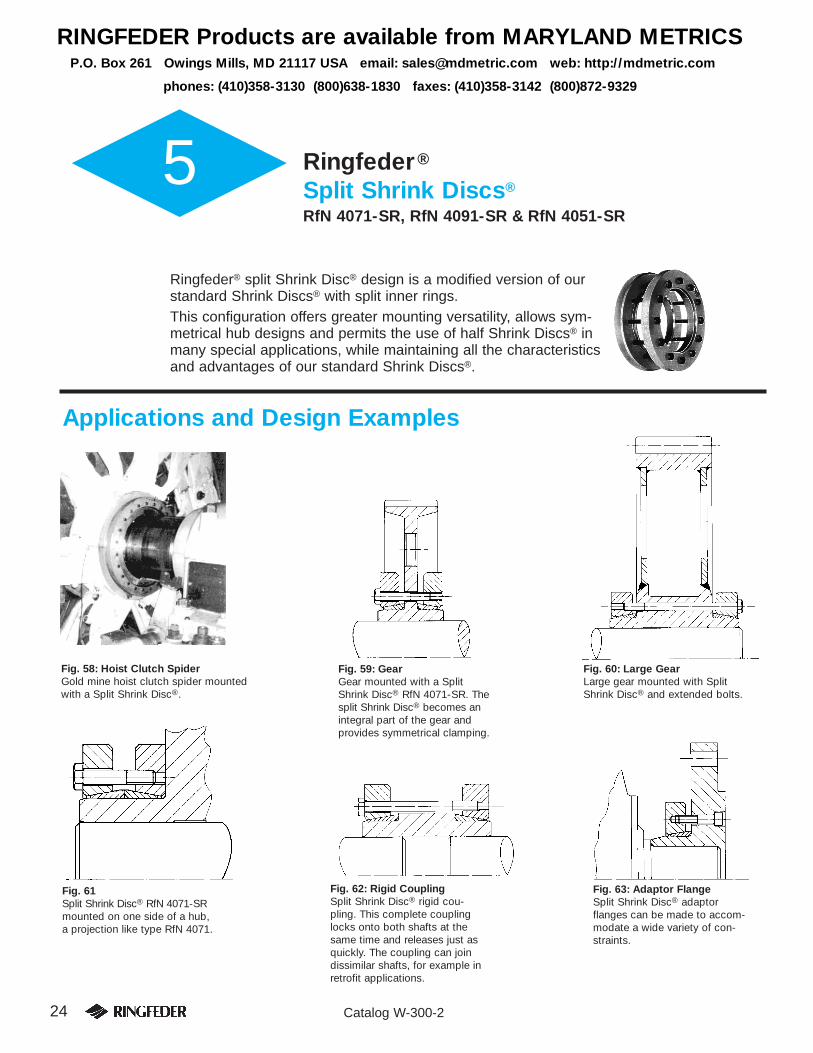
5 Ringfeder®
Split Shrink Discs®
RfN 4071-SR, RfN 4091-SR & RfN 4051-SR
Ringfeder® split Shrink Disc® design is a modified version of ourstandard Shrink Discs® with split inner rings.This configuration offers greater mounting versatility, allows sym-metrical hub designs and permits the use of half Shrink Discs® inmany special applications, while maintaining all the characteristicsand advantages of our standard Shrink Discs®.
Applications and Design Examples
Fig. 58: Hoist Clutch SpiderGold mine hoist clutch spider mountedwith a Split Shrink Disc®.
Fig. 60: Large GearLarge gear mounted with SplitShrink Disc® and extended bolts.
Fig. 61Split Shrink Disc® RfN 4071-SRmounted on one side of a hub,a projection like type RfN 4071.
Fig. 62: Rigid CouplingSplit Shrink Disc® rigid cou-pling. This complete couplinglocks onto both shafts at thesame time and releases just asquickly. The coupling can joindissimilar shafts, for example inretrofit applications.
Fig. 63: Adaptor FlangeSplit Shrink Disc® adaptorflanges can be made to accom-modate a wide variety of con-straints.
Fig. 59: GearGear mounted with a SplitShrink Disc® RfN 4071-SR. Thesplit Shrink Disc® becomes anintegral part of the gear andprovides symmetrical clamping.
RINGFEDER Products are available from MARYLAND METRICSP.O. Box 261 Owings Mills, MD 21117 USA email: [email protected] web: http://mdmetric.com
phones: (410)358-3130 (800)638-1830 faxes: (410)358-3142 (800)872-9329
25Catalog W-300-2
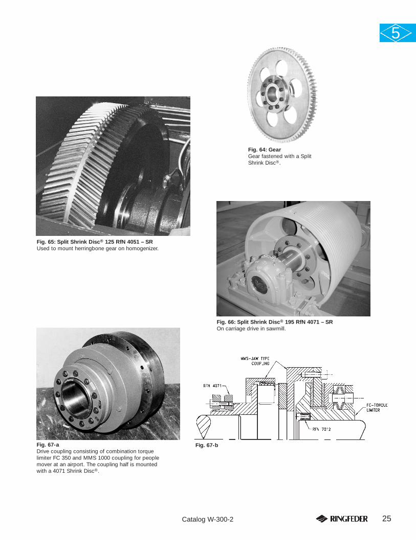
Fig. 64: GearGear fastened with a SplitShrink Disc®.
5
Fig. 65: Split Shrink Disc® 125 RfN 4051 – SRUsed to mount herringbone gear on homogenizer.
Fig. 67-aDrive coupling consisting of combination torquelimiter FC 350 and MMS 1000 coupling for peoplemover at an airport. The coupling half is mountedwith a 4071 Shrink Disc®.
Fig. 66: Split Shrink Disc® 195 RfN 4071 – SROn carriage drive in sawmill.
Fig. 67-b
26 Catalog W-300-2
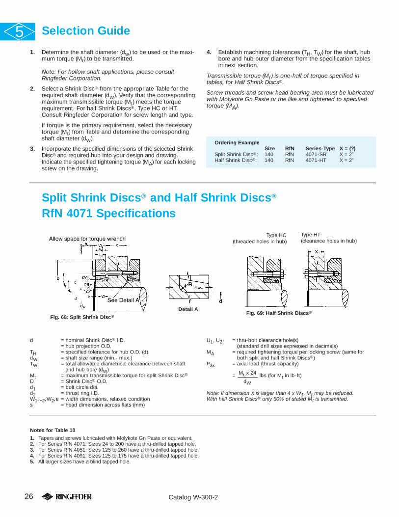
1. Determine the shaft diameter (dw) to be used or the maxi-mum torque (Mt) to be transmitted.
Note: For hollow shaft applications, please consultRingfeder Corporation.
2. Select a Shrink Disc® from the appropriate Table for therequired shaft diameter (dw). Verify that the correspondingmaximum transmissible torque (Mt) meets the torquerequirement. For half Shrink Discs®, Type HC or HT,Consult Ringfeder Corporation for screw length and type.
If torque is the primary requirement, select the necessarytorque (Mt) from Table and determine the correspondingshaft diameter (dw).
3. Incorporate the specified dimensions of the selected ShrinkDisc® and required hub into your design and drawing.Indicate the specified tightening torque (MA) for each lockingscrew on the drawing.
4. Establish machining tolerances (TH, TW) for the shaft, hubbore and hub outer diameter from the specification tablesin next section.
Transmissible torque (Mt) is one-half of torque specified intables, for Half Shrink Discs®.
Screw threads and screw head bearing area must be lubricatedwith Molykote Gn Paste or the like and tightened to specifiedtorque (MA).
Selection Guide5
Split Shrink Discs® and Half Shrink Discs®
RfN 4071 Specifications
See Detail A
Allow space for torque wrench
Fig. 68: Split Shrink Disc®Fig. 69: Half Shrink Discs®
Type HC(threaded holes in hub)
Type HT(clearance holes in hub)
Detail A
d = nominal Shrink Disc® I.D.= hub projection O.D.
TH = specified tolerance for hub O.D. (d)dW = shaft size range (min.- max.)TW = total allowable diametrical clearance between shaft
and hub bore (dW)Mt = maximum transmissible torque for split Shrink Disc®
D = Shrink Disc® O.D.d1 = bolt circle dia.d2 = thrust ring I.D.W1,L2,W2,e = width dimensions, relaxed conditions = head dimension across flats (mm)
U1, U2 = thru-bolt clearance hole(s)(standard drill sizes expressed in decimals)
MA = required tightening torque per locking screw (same forboth split and half Shrink Discs®)
Pax = axial load (thrust capacity)
= Mt x 24 lbs (for Mt in lb-ft)dW
Note: If dimension X is larger than 4 x W1, Mt may be reduced. With half Shrink Discs® only 50% of stated Mt is transmitted.
Notes for Table 10
1. Tapers and screws lubricated with Molykote Gn Paste or equivalent.2. For Series RfN 4071: Sizes 24 to 200 have a thru-drilled tapped hole.3. For Series RfN 4051: Sizes 125 to 260 have a thru-drilled tapped hole.4. For Series RfN 4091: Sizes 125 to 175 have a thru-drilled tapped hole.5. All larger sizes have a blind tapped hole.
Ordering ExampleSize RfN Series-Type X = (?)
Split Shrink Disc®: 140 RfN 4071-SR X = 2”Half Shrink Disc®: 140 RfN 4071-HT X = 2”

27Catalog W-300-2
RfN 4071-SR Specifications, continued 5
24 .945 .748 125 1.97 1.417 1.024 .354 .463 .600 .315 .108 6 M 5 8 .281 .219+0 .827 184
30 1.181 –.0013 .945 .0007 .050 221 2.36 1.732 1.260 .394 .502 .640 .354 .108 7 M 5 8 .281 .2191.024 273
36 1.417 1.102 325 2.83 2.047 1.496 .433 .541 .699 .394 .108 5 M 6 10 .328 .266
+01.220 465
44 1.732 –.00151.339 524 3.15 2.402 1.850 .492 .600 .758 .433 .108 7 M 6 10 .328 .2661.417 634
50 1.969 1.496 693 3.54 2.756 2.087 .531 .640 .797 .472 .108 8 M 6 10 .328 .2661.654 1 018
55 2.165 1.654 .0013.090 856 3.94 2.953 2.283 .551 .699 .856 .512 .148 8 M 6 10 .328 .2661.890 1 387
62 2.441 1.890 1 365 4.33 3.386 2.598 .551 .699 .856 .512 .148 10 M 6 10 .328 .266
+02.047 1 770
68 2.677 –.00181.969 1 475 4.53 3.386 2.835 .551 .699 .856 .512 .148 10 M 6 10 .328 .2662.362 2 323
75 2.953 2.165 1 844 5.43 3.937 3.110 .630 .778 .994 .551 .148 7 M 8 13 .406 .3592.559 .110 2 914
80 3.150 2.362.0019
2 360 5.71 3.937 3.307 .630 .778 .994 .551 .148 7 M 8 13 .406 .3592.756 3 393
90 3.543 2.559 3 504 6.10 4.488 3.701 .728 .906 1.122 .669 .177 10 M 8 13 .406 .359
+02.953 5 348
100 3.937 –.00212.756 .130 5 089 6.69 4.822 4.094 .807 1.004 1.220 .748 .197 12 M 8 13 .406 .3593.150 6 638
110 4.331 2.953 5 311 7.28 5.354 4.488 .906 1.122 1.398 .866 .217 9 M10 17 .500 .4383.346 7 966
125 4.921 3.346 8 114 8.46 6.299 5.276 1.024 1.260 1.535 .906 .236 12 M10 17 .500 .4383.740 11 064
140 5.512 3.740 11 138 9.06 6.890 5.748 1.102 1.388 1.703 1.024 .285 10 M12 19 .594 .5314.134 .0027 14 826
155 6.102 +0 4.134 16 227 10.43 7.559 6.496 1.181 1.467 1.781 1.102 .285 12 M12 19 .594 .531–.0025 4.528 20 653
165 6.496 4.528 22 866 11.42 8.268 6.890 1.299 1.594 1.988 1.220 .295 8 M16 24 .750 .7194.921 .190 28 766
175 6.890 4.921 26 554 11.81 8.661 7.283 1.299 1.594 1.988 1.220 .295 8 M16 24 .750 .7195.315 33 192
185 7.283 5.315 38 355 12.99 9.291 7.677 1.594 1.890 2.283 1.496 .295 10 M16 24 .750 .7195.709 45 731
195 7.677 5.512 47 944 13.78 9.685 8.268 1.594 1.890 2.283 1.496 .295 12 M16 24 .750 .719
+06.102 60 114
200 7.874 –.00285.906 .0031 54 582 13.78 9.685 8.268 1.594 1.890 2.283 1.496 .295 12 M16 24 .750 .7196.299 63 434
220 8.661 6.299 70 072 14.57 10.630 9.055 2.028 2.343 2.736 1.850 .315 15 M16 24 .750 .7196.693 81 136
240 9.449 6.693 .290 88 512 15.94 11.614 9.764 2.106 2.441 2.953 1.929 .335 12 M20 30 .906 .8757.480 115 066
260 10.236 7.480 120 966 16.93 12.638 10.551 2.323 2.657 3.169 2.126 .335 14 M20 30 .906 .875
+08.268 151 208
280 11.024 –.00328.268 160 059 18.11 13.622 11.339 2.579 2.972 3.484 2.362 .394 16 M20 30 .906 .8759.055 .0035 199 152
300 11.811 9.055 202 840 19.09 14.331 12.126 2.736 3.130 3.642 2.520 .394 18 M20 30 .906 .8759.646 232 344
320 12.598 9.449 230 131 20.47 15.197 12.913 2.736 3.130 3.642 2.520 .394 20 M20 30 .906 .87510.236 275 862
340 13.386 9.843 287 664 22.44 16.063 13.701 2.972 3.406 3.917 2.795 .433 24 M20 30 .906 .87510.630 339 296
350 13.780 10.630 .330 326 019 22.83 17.008 14.094 3.091 3.524 4.035 2.874 .433 24 M20 30 .906 .875
+011.220 368 800
360 14.173 –.003511.024 341 509 23.23 17.008 14.488 3.091 3.524 4.035 2.874 .433 24 M20 30 .906 .87511.614 .0040 385 027
380 14.961 11.417 418 219 25.39 18.031 15.236 3.169 3.642 4.232 2.992 .472 20 M24 36 1.063 1.03112.205 485 341
390 15.354 11.811 460 262 25.98 18.425 15.630 3.169 3.642 4.232 2.992 .472 21 M24 36 1.063 1.03112.598 529 597
400 15.748 12.402 494 192 26.77 18.898 16.024 3.169 3.642 4.232 2.992 .472 21 M24 36 1.063 1.03112.992 548 774
420 16.535 12.992 575 328 27.17 19.843 16.811 3.720 4.193 4.783 3.386 .472 24 M24 36 1.063 1.03113.780.0044
663 840
440 17.323 13.386 594 506 29.53 20.748 17.598 3.976 4.469 5.059 3.583 .492 24 M24 36 1.063 1.031
+014.173 676 379
460 18.110 –.003814.173 .390 737 600 30.31 21.535 18.425 3.976 4.469 5.059 3.583 .492 28 M24 36 1.063 1.03114.961 840 864
480 18.898 14.961 862 992 31.50 22.441 19.213 4.193 4.685 5.276 3.780 .492 30 M24 36 1.063 1.03115.748 966 256
500 19.685 15.748 .0048 967 731 33.46 23.228 20.000 4.193 4.685 5.354 3.780 .492 24 M27 41 1.188 1.15616.535 1 073 208
MAlb-ft
3
3
9
9
9
9
9
9
22
22
22
22
44
44
74
74
185
185
185
185
185
185
362
362
362
362
362
362
362
362
620
620
620
620
620
620
620
922
Shaft/Hub dimensions Shrink Disc® dimensions Locking screws DIN 931 - 10.9RfN max.4071 d TH dW TW R1max. Mt D d1 d2 W W1 W2 L2 e Qty Size s U1 U2Size inches lb-ft inches mm inches
Table 10: Split Shrink Disc® RfN 4071–SRMaterial: Alloy Steel*
* Stainless steel available upon request.

28 Catalog W-300-2
1
Detail ASee Detail A
Allow space for torque wrench
Fig. 70: Split Shrink Disc®
Type HC(threaded
holes in hub)
Type HT(clearance holes in hub)
d = nominal Shrink Disc® I.D.= hub projection O.D.
TH = specified tolerance for hub O.D. (d)dW = shaft size range (min.- max.)TW = total allowable diametrical clearance
between shaft and hub bore (dW)Mt = maximum transmissible torqueD = Shrink Disc® O.D.d1 = bolt circle dia.d2 = thrust ring I.D.Pax = axial load (thrust capacity)
= Mt x 24 lbs (for Mt in lb-ft)dW
Type SR
Light Duty Split Shrink Discs® RfN 4051-SR Specifications5
125 4.921 3.740 7 782 7.28 6.220 5.079 .965 1.201 1.476 .866 .236 8 M10 17 .500 .4384.134 .0027 10 179
140 5.512 4.331 10 916 8.66 6.890 5.669 .965 1.201 1.476 .866 .236 9 M10 17 .500 .4384.921 15 121
155 6.102 +0 5.118 17 702 9.65 7.559 6.260 .965 1.201 1.476 .866 .236 11 M10 17 .500 .438–.0025 5.512 21 390
165 6.496 5.315 23 603 10.24 8.268 6.654 1.102 1.417 1.732 1.024 .315 10 M12 19 .594 .5315.709 28 398
175 6.890 5.709 28 766 10.83 8.661 7.047 1.102 1.417 1.732 1.024 .315 11 M12 19 .594 .5316.102 .190 33 930
185 7.283 6.102 .0031 34 372 11.61 8.858 7.441 1.102 1.417 1.732 1.024 .315 12 M12 19 .594 .5316.496 39 830
195 7.677 6.496 46 469 12.40 9.331 7.835 1.299 1.614 1.929 1.220 .315 15 M12 19 .594 .531
+06.890 53 476
200 7.874 –.00286.890 54 582 12.99 9.528 8.031 1.299 1.614 1.929 1.220 .315 16 M12 19 .594 .5317.283 62 327
220 8.661 7.087 61 073 13.58 10.433 8.819 1.496 1.850 2.244 1.417 .354 10 M16 24 .750 .7197.874 77 448
240 9.449 7.874 83 349 14.57 11.417 9.606 1.496 1.850 2.244 1.417 .354 12 M16 24 .750 .7198.465 .0035 99 207
260 10.236 8.661 109 902 15.55 12.205 10.433 1.713 2.067 2.461 1.575 .354 14 M16 24 .750 .719
+09.252 127 605
280 11.024 –.00329.055 126 130 16.73 13.110 11.220 1.949 2.343 2.736 1.811 .394 16 M16 24 .750 .7199.843 153 421
300 11.811 9.843 158 584 18.11 14.094 12.008 1.949 2.343 2.736 1.811 .394 18 M16 24 .750 .71910.630 188 088
320 12.598 10.630 191 776 19.49 14.882 12.795 1.949 2.382 2.776 1.890 .433 20 M16 24 .750 .71911.417 .250 225 706
340 13.386 11.417 221 280 21.06 15.827 13.583 1.949 2.382 2.776 1.890 .433 21 M16 24 .750 .71912.008 .0040 248 571
350 13.780 11.811 274 387 21.46 16.260 13.976 2.264 2.697 3.209 2.126 .433 16 M20 30 .906 .875
+012.205 295 040
360 14.173 –.003511.811 265 536 21.85 16.654 14.370 2.264 2.697 3.209 2.126 .433 16 M20 30 .906 .87512.598 306 104
380 14.961 12.598 320 856 23.03 17.402 15.236 2.500 2.972 3.484 2.362 .472 18 M20 30 .906 .87512.992 344 459
390 15.354 12.992 372 488 23.43 17.795 15.630 2.598 3.071 3.583 2.362 .472 20 M20 30 .906 .87513.780 425 595
400 15.748 13.386 405 680 24.21 18.189 16.024 2.598 3.071 3.583 2.362 .472 21 M20 30 .906 .87514.173 .0044 .330 461 738
420 16.535 13.780 426 333 24.80 19.094 16.811 2.756 3.228 3.740 2.520 .472 22 M20 30 .906 .87514.567 483 128
440 17.323 14.567 499 355 25.98 19.882 17.598 2.756 3.228 3.740 2.520 .472 24 M20 30 .906 .875
+015.354 562 051
460 18.110 –.003815.354 619 584 26.97 20.748 18.425 3.091 3.602 4.114 2.795 .512 28 M20 30 .906 .87516.142 689 656
480 18.898 16.142 .390 657 202 28.15 21.535 19.213 3.091 3.602 4.114 2.795 .512 28 M20 30 .906 .87516.732 .0048 712 522
500 19.685 16.732 727 274 29.53 22.323 20.000 3.091 3.602 4.114 2.795 .512 30 M20 30 .906 .87517.323 786 282
MAlb-ft
44
44
44
74
74
74
74
74
185
185
185
185
185
185
185
362
362
362
362
362
362
362
362
362
362
Shaft/Hub dimensions Shrink Disc® dimensions Locking screws DIN 931 - 10.9RfN max.4051 d TH dW TW R1max. Mt D d1 d2 W W1 W2 L2 e Qty Size s U1 U2Size inches lb-ft inches mm inches
Table 11: Light Duty Split Shrink Disc® RfN 4051–SRMaterial: Alloy Steel*
* Stainless steel available upon request.
Fig. 71: Half Shrink Discs®
Note: If dimension X is larger than 4xW1, Mt may be reduced. With half Shrink Discs® only 50% of stated Mt is transmitted.W1, W2, e = width dimensions, relaxed conditions = head dim. across flats (mm)U1, U2 = thru-bolt clearance hole(s) (standard drill sizes
expressed in decimals)MA = required tightening torque per locking screw
(same for both split and half Shrink Discs®)
Notes 1. Tapers and screws lubricated with Molykote Gn paste or equivalent.
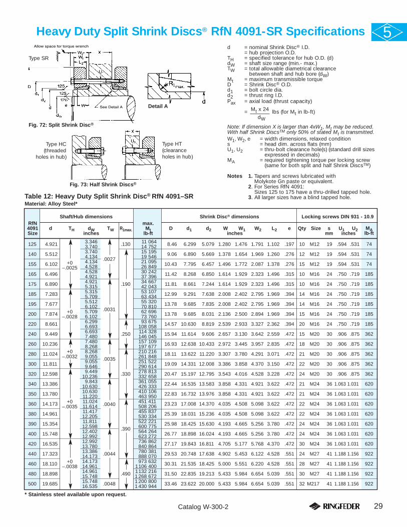
29Catalog W-300-2
Heavy Duty Split Shrink Discs® RfN 4091-SR Specifications 5
125 4.921 3.346 .130 11 064 8.46 6.299 5.079 1.280 1.476 1.791 1.102 .197 10 M12 19 .594 .5313.740 14 752
140 5.512 3.740 15 195 9.06 6.890 5.669 1.378 1.654 1.969 1.260 .276 12 M12 19 .594 .5314.134 .0027 19 546
155 6.102 +0 4.134 21 095 10.43 7.795 6.457 1.496 1.772 2.087 1.378 .276 15 M12 19 .594 .531–.0025 4.528 26 849
165 6.496 4.528 30 242 11.42 8.268 6.850 1.614 1.929 2.323 1.496 .315 10 M16 24 .750 .7194.921 37 396
175 6.890 4.921 .190 34 667 11.81 8.661 7.244 1.614 1.929 2.323 1.496 .315 10 M16 24 .750 .7195.315 42 043
185 7.283 5.315 53 107 12.99 9.291 7.638 2.008 2.402 2.795 1.969 .394 14 M16 24 .750 .7195.709 63 434
195 7.677 5.512 55 320 13.78 9.685 7.835 2.008 2.402 2.795 1.969 .394 14 M16 24 .750 .719
+06.102 70 810
200 7.874 –.00285.709 .0031 62 696 13.78 9.685 8.031 2.136 2.500 2.894 1.969 .394 15 M16 24 .750 .7196.102 73 760
220 8.661 6.299 93 675 14.57 10.630 8.819 2.539 2.933 3.327 2.362 .394 20 M16 24 .750 .7196.693 108 058
240 9.449 6.693 .250 114 328 15.94 11.614 9.606 2.657 3.130 3.642 2.559 .472 15 M20 30 .906 .8757.480 146 045
260 10.236 7.480 157 109 16.93 12.638 10.433 2.972 3.445 3.957 2.835 .472 18 M20 30 .906 .875
+08.268 197 677
280 11.024 –.00328.268 210 216 18.11 13.622 11.220 3.307 3.780 4.291 3.071 .472 21 M20 30 .906 .8759.055 .0035 261 848
300 11.811 9.055 251 522 19.09 14.331 12.008 3.386 3.858 4.370 3.150 .472 22 M20 30 .906 .8759.646 290 614
320 12.598 9.449 .330 278 813 20.47 15.197 12.795 3.543 4.016 4.528 3.228 .472 24 M20 30 .906 .87510.236 332 658
340 13.386 9.843 361 055 22.44 16.535 13.583 3.858 4.331 4.921 3.622 .472 21 M24 36 1.063 1.03110.630 426 333
350 13.780 10.630 410 106 22.83 16.732 13.976 3.858 4.331 4.921 3.622 .472 21 M24 36 1.063 1.031
+011.220 463 950
360 14.173 –.003511.024 451 411 23.23 17.008 14.370 4.035 4.508 5.098 3.622 .472 22 M24 36 1.063 1.03111.614 .0040 508 206
380 14.961 11.417 455 837 25.39 18.031 15.236 4.035 4.508 5.098 3.622 .472 22 M24 36 1.063 1.03112.205 530 334
390 15.354 11.811 522 221 25.98 18.425 15.630 4.193 4.665 5.256 3.780 .472 24 M24 36 1.063 1.03112.598 .390 600 775
400 15.748 12.402 564 264 26.77 18.898 16.024 4.193 4.665 5.256 3.780 .472 24 M24 36 1.063 1.03112.992 623 272
420 16.535 12.992 736 862 27.17 19.843 16.811 4.705 5.177 5.768 4.370 .472 30 M24 36 1.063 1.03113.780 840 864
440 17.323 13.386 .0044 780 381 29.53 20.748 17.638 4.902 5.453 6.122 4.528 .551 24 M27 41 1.188 1.156
+014.173 888 070
460 18.110 –.003814.173 973 632 30.31 21.535 18.425 5.000 5.551 6.220 4.528 .551 28 M27 41 1.188 1.15614.961 1106 400
480 18.898 14.961 .490 1132 216 31.50 22.835 19.213 5.433 5.984 6.654 5.039 .551 30 M27 41 1.188 1.15615.748 1 268 672
500 19.685 15.748 .0048 1 200 800 33.46 23.622 20.000 5.433 5.984 6.654 5.039 .551 32 M217 41 1.188 1.15616.535 1 430 944
MAlb-ft
74
74
74
185
185
185
185
185
185
362
362
362
362
362
620
620
620
620
620
620
620
922
922
922
922
Shaft/Hub dimensions Shrink Disc® dimensions Locking screws DIN 931 - 10.9RfN max.4091 d TH dW TW R1max. Mt D d1 d2 W W1 W2 L2 e Qty Size s U1 U2Size inches lb-ft inches mm inches
Table 12: Heavy Duty Split Shrink Disc® RfN 4091–SRMaterial: Alloy Steel*
* Stainless steel available upon request.
Type HC(threaded
holes in hub)
Type HT(clearance holes in hub)
d = nominal Shrink Disc® I.D.= hub projection O.D.
TH = specified tolerance for hub O.D. (d)dW = shaft size range (min.- max.)TW = total allowable diametrical clearance
between shaft and hub bore (dW)Mt = maximum transmissible torqueD = Shrink Disc® O.D.d1 = bolt circle dia.d2 = thrust ring I.D.Pax = axial load (thrust capacity)
= Mt x 24 lbs (for Mt in lb-ft)dW
Fig. 73: Half Shrink Discs®
Note: If dimension X is larger than 4xW1, Mt may be reduced. With half Shrink DiscsTM only 50% of stated Mt is transmitted.W1, W2, e = width dimensions, relaxed conditions = head dim. across flats (mm)U1, U2 = thru-bolt clearance hole(s) (standard drill sizes
expressed in decimals)MA = required tightening torque per locking screw
(same for both split and half Shrink DiscsTM)
Notes 1. Tapers and screws lubricated with Molykote Gn paste or equivalent.
2. For Series RfN 4091:Sizes 125 to 175 have a thru-drilled tapped hole.
3. All larger sizes have a blind tapped hole.
1
Detail ASee Detail A
Allow space for torque wrench
Fig. 72: Split Shrink Disc®
Type SR
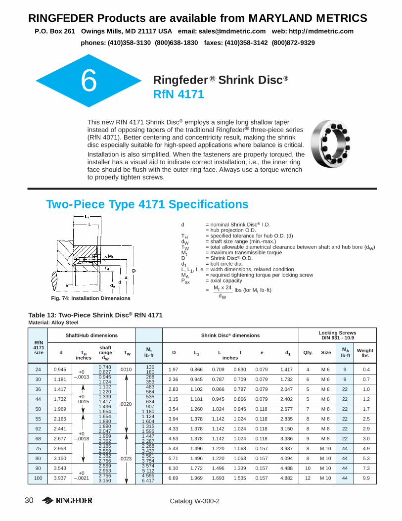
30 Catalog W-300-2
6 Ringfeder® Shrink Disc®
RfN 4171
This new RfN 4171 Shrink Disc® employs a single long shallow taperinstead of opposing tapers of the traditional Ringfeder® three-piece series(RfN 4071). Better centering and concentricity result, making the shrinkdisc especially suitable for high-speed applications where balance is critical.
Installation is also simplified. When the fasteners are properly torqued, theinstaller has a visual aid to indicate correct installation; i.e., the inner ringface should be flush with the outer ring face. Always use a torque wrenchto properly tighten screws.
Two-Piece Type 4171 Specifications
d = nominal Shrink Disc® I.D.= hub projection O.D.
TH = specified tolerance for hub O.D. (d)dW = shaft size range (min.-max.)TW = total allowable diametrical clearance between shaft and hub bore (dW)Mt = maximum transmissible torqueD = Shrink Disc® O.D.d1 = bolt circle dia.L, L1, I, e = width dimensions, relaxed conditionMA = required tightening torque per locking screwPax = axial capacity
= Mt x 24 lbs (for Mt lb-ft)dWFig. 74: Installation Dimensions
Shaft/Hub dimensions Shrink Disc® dimensions Locking ScrewsDIN 931 - 10.9
RfN4171 shaftsize d TH range TW
Mt D L1 L I e d1 Qty. SizeMA Weight
inches dWlb-ft inches lb-ft lbs
24 0.945 0.748 .0010 136 1.97 0.866 0.709 0.630 0.079 1.417 4 M 6 9 0.4+0 0.827 180
30 1.181 –.0013 0.945 288 2.36 0.945 0.787 0.709 0.079 1.732 6 M 6 9 0.71.024 353
36 1.417 1.102 483 2.83 1.102 0.866 0.787 0.079 2.047 5 M 8 22 1.01.220 584
44 1.732 +0 1.339 535 3.15 1.181 0.945 0.866 0.079 2.402 5 M 8 22 1.2–.0015 1.417 .0020 634
50 1.969 1.496 907 3.54 1.260 1.024 0.945 0.118 2.677 7 M 8 22 1.71.654 1 180
55 2.165 1.654 1 124 3.94 1.378 1.142 1.024 0.118 2.835 8 M 8 22 2.51.890 1 604
62 2.441 1.890 1 315 4.33 1.378 1.142 1.024 0.118 3.150 8 M 8 22 2.9+0 2.047 1 595
68 2.677 –.0018 1.969 1 447 4.53 1.378 1.142 1.024 0.118 3.386 9 M 8 22 3.02.362 2 287
75 2.953 2.165 2 268 5.43 1.496 1.220 1.063 0.157 3.937 8 M 10 44 4.92.559 3 437
80 3.150 2.362 2 561 5.71 1.496 1.220 1.063 0.157 4.094 8 M 10 44 5.32.756 .0023 3 754
90 3.543 2.559 3 574 6.10 1.772 1.496 1.339 0.157 4.488 10 M 10 44 7.3+0 2.953 5 112
100 3.937 –.0021 2.756 4 595 6.69 1.969 1.693 1.535 0.157 4.882 12 M 10 44 9.93.150 6 417
Table 13: Two-Piece Shrink Disc® RfN 4171Material: Alloy Steel
RINGFEDER Products are available from MARYLAND METRICSP.O. Box 261 Owings Mills, MD 21117 USA email: [email protected] web: http://mdmetric.com
phones: (410)358-3130 (800)638-1830 faxes: (410)358-3142 (800)872-9329

31Catalog W-300-2
Two-Piece Type 4171 Specifications, continued 6
Shaft/Hub dimensions Shrink Disc® dimensions Locking ScrewsDIN 931 - 10.9
RfN4171 shaftsize d TH range TW
Mt D L1 L I e d1 Qty. SizeMA Weight
inches dWlb ft inches lb ft lbs
110 4.331 +0 3.150 6 594 7.28 2.244 1.929 1.732 0.197 5.354 10 M 12 74 13.5–.0021 3.543 8 639
125 4.921 3.543 8 925 8.46 2.402 2.087 1.890 0.236 6.299 12 M 12 74 19.83.937 .0027 11 580
140 5.512 3.937 11 359 9.06 2.638 2.283 2.047 0.236 6.811 10 M 14 118 24.34.331 14 014
155 6.102 +0 4.331 15 490 10.35 2.795 2.441 2.205 0.236 7.480 12 M 14 118 34.4–.0025 4.724 19 178
165 6.496 4.724 19 915 11.42 3.071 2.677 2.402 0.276 8.031 10 M 16 184 48.55.118 23 603
175 6.890 5.118 27 291 11.81 3.071 2.677 2.362 0.315 8.425 12 M 16 184 50.75.512 32 454
185 7.283 5.512 .0031 36 511 12.99 3.740 3.346 3.031 0.315 8.819 14 M 16 184 79.45.906 43 150
200 7.784 5.906 44 994 13.78 3.740 3.346 3.031 0.315 9.449 16 M 16 184 88.2+0 6.299 52 738
220 8.661 –.0028 6.299 72 285 14.57 4.567 4.055 3.701 0.354 10.630 16 M 20 361 116.96.693 82 611
240 9.449 6.693 84 824 15.94 4.724 4.213 3.819 0.394 11.654 18 M 20 361 145.57.480 107 690
260 10.236 7.480 118 016 16.93 5.197 4.685 4.291 0.394 12.521 21 M 20 361 178.6
+08.268 .0035 147 520
280 11.024 –.00328.268 143 094 18.11 5.709 5.197 4.803 0.394 13.386 22 M 20 361 224.99.055 176 286
300 11.811 9.055 206 528 19.09 6.102 5.512 5.118 0.394 14.173 20 M 24 620 260.29.646 236 770
320 12.598 9.449 221 280 20.47 6.102 5.512 5.118 0.394 14.961 21 M 24 620 302.110.236 263 323
340 13.386 10.039 263 323 22.05 6.693 6.102 5.630 0.472 15.827 22 M 24 620 392.510.630 .0040 298 728
360 14.173 +0 11.024 331 920 23.23 6.850 6.260 5.787 0.472 16.693 24 M 24 620 445.4–.0035 11.811 387 240
380 14.961 11.811 354 048 25.00 7.087 6.417 5.866 0.551 17.638 18 M 27 922 765.112.402 396 829
390 15.354 12.205 371 013 25.00 7.087 6.417 5.866 0.551 18.031 18 M 27 922 529.212.598 396 829
400 15.748 12.402 418 957 25.59 7.480 6.811 6.260 0.551 18.701 20 M 27 922 575.312.795 446 248
420 16.535 12.795 442 560 26.38 7.874 7.205 6.614 0.591 19.488 21 M 27 922 648.313.189 .0044 473 539
440 17.323 12.992 499 355 28.35 8.268 7.598 7.008 0.591 20.394 24 M 27 922 811.413.780 569 427
460 18.110 +0 13.780 562 051 30.31 8.268 7.598 7.008 0.591 21.181 25 M 27 922 948.2–.0038 14.764 638 024
480 18.898 14.764 678 592 31.50 9.055 8.386 7.795 0.591 21.969 27 M 27 922 1133.415.748 764 154
500 19.685 15.748 .0048 775 955 33.46 9.055 8.386 7.795 0.591 22.835 28 M 27 922 1301.016.535 861 517
Table 14: Two-Piece Shrink Disc® RfN 4171Material: Alloy Steel
Light Duty and Heavy Duty available upon request.

32 Catalog W-300-2
7 RfC Low Inertia Series Shrink Discs®
Sizes 10 to 50
These low inertia units are designed for applications where maximum clamp-ing is needed and minimum weight is desired. These Shrink Discs® offer theflexibility of the standard RfN 4071 units for smaller shaft sizes. Available forshafts from 1/4 to 1-11/16 inches. Special sizes and material on request.
Low Inertia Series Shrink Discs® Specifications
Fig. 75: Low Inertia Shrink Disc®
Fig. 76: Rear Thrust Collar
Detail A
d = nominal Shrink Disc® I.D.= hub projection O.D.
TH = specified tolerance for hub O.D. (d)dW = nominal shaft and bore dimensionTW = total allowable diametrical clearance between shaft and
hub bore (dW)Mt = maximum transmissible torqueD = Shrink Disc® O.D.d1 = bolt circle dia.d2 = thrust ring I.D.L, L1, e = width dimensions, relaxed conditionL2 = thickness of thrust ringAF = distance across flatsMA = required tightening torque per locking screws = head dimension across flats (mm)
6 .236 3610 RFC 4073 0.394 6.35 .250 0.0005 55 1.18 0.866 0.472 0.394 .472 .582 0.197 0.039 1.06 4 M4x10 7
8 .315 1449 .354 200
13 RFC 4073 0.512 +0 9.5 .375 250 1.30 0.985 0.591 0.394 .472 .610 0.197 0.039 1.25 4 M5x10 8–.001 11 .433 41012 .472 460
16 RFC 4051 0.630 12.7 .500 0.0007 554 1.50 1.102 0.709 0.394 .551 .689 0.217 0.079 1.44 4 M5x12 814 .551 73016 .630 980
24 RFC 4051 0.945 19 .748 1 500 1.875 1.417 1.024 0.394 .610 .748 0.236 0.108 1.75 6 M5x14 8+0 20 .787 1 750
–.0013 22.2 .875 0.065 1 90030 RFC 4051 1.181 24 .945 2 300 2.10 1.732 1.260 0.472 .689 .827 0.276 0.108 2.05 7 M5x16 8
26 1.024 2 80027 1.063 0.0010 3 500
36 RFC 4051 1.417 28 1.102 4 130 2.50 2.047 1.496 0.551 .768 .925 0.315 0.108 2.44 5 M6x18 1028.6 1.125 4 36532 1.260 5 690
+0 34 1.339 5 40044 RFC 4051 1.732 –.0015 34.93 1.375 5 900 2.85 2.402 1.850 0.630 .847 1.000 0.354 0.108 2.75 6 M6x20 10
37 1.457 6 90038 1.496 0.0013 6 400
50 RFC 4051 1.969 41.28 1.625 8 000 3.19 2.756 2.087 0.709 .925 1.083 0.394 0.108 3.00 6 M6x20 1042.85 1.687 9 000
MAlb-in
12
25
25
30
30
75
75
75
Locking ScrewsShaft/Hub dimensions Shrink Disc® dimensions DIN 933 - 10.9 HHCS
Size d TH dW TW R1 Mt D d1 d2 I L L1 L2 e AF Qty. Size sinches mm inches max. lb-in inches mm
Table 15: RfC Low Inertia Series RfC 4051Material: Alloy Steel*
* Stainless steel available upon request.Larger sizes are available upon request.
R1max
RINGFEDER Products are available from MARYLAND METRICSP.O. Box 261 Owings Mills, MD 21117 USA email: [email protected] web: http://mdmetric.com
phones: (410)358-3130 (800)638-1830 faxes: (410)358-3142 (800)872-9329
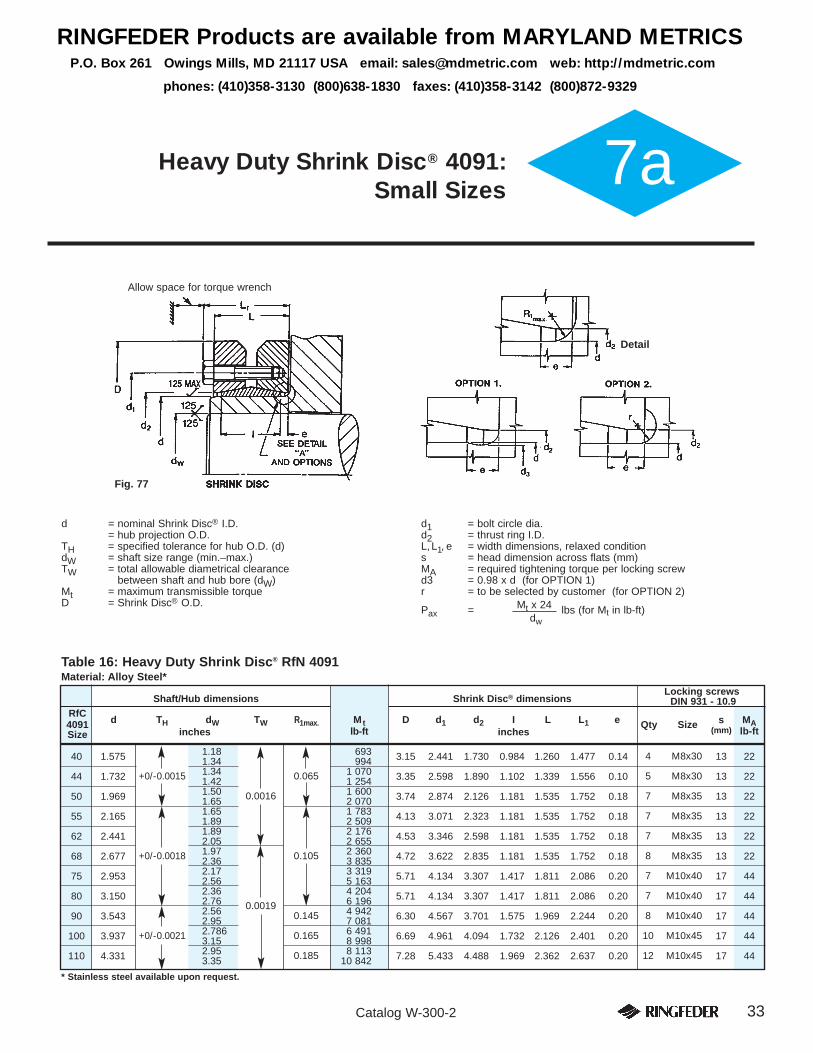
33Catalog W-300-2
7aHeavy Duty Shrink Disc® 4091: Small Sizes
Table 16: Heavy Duty Shrink Disc® RfN 4091Material: Alloy Steel*
* Stainless steel available upon request.
40 1.575 1.18 693 3.15 2.441 1.730 0.984 1.260 1.477 0.14 4 M8x301.34 994
44 1.732 +0/-0.0015 1.34 0.065 1 070 3.35 2.598 1.890 1.102 1.339 1.556 0.10 5 M8x301.42 1 254
50 1.969 1.50 0.0016 1 600 3.74 2.874 2.126 1.181 1.535 1.752 0.18 7 M8x351.65 2 070
55 2.165 1.65 1 783 4.13 3.071 2.323 1.181 1.535 1.752 0.18 7 M8x351.89 2 509
62 2.441 1.89 2 176 4.53 3.346 2.598 1.181 1.535 1.752 0.18 7 M8x352.05 2 655
68 2.677 +0/-0.0018 1.97 0.105 2 360 4.72 3.622 2.835 1.181 1.535 1.752 0.18 8 M8x352.36 3 835
75 2.953 2.17 3 319 5.71 4.134 3.307 1.417 1.811 2.086 0.20 7 M10x402.56 5 163
80 3.150 2.36 4 204 5.71 4.134 3.307 1.417 1.811 2.086 0.20 7 M10x402.76 0.0019 6 196
90 3.543 2.56 0.145 4 942 6.30 4.567 3.701 1.575 1.969 2.244 0.20 8 M10x402.95 7 081
100 3.937 +0/-0.0021 2.786 0.165 6 491 6.69 4.961 4.094 1.732 2.126 2.401 0.20 10 M10x453.15 8 998
110 4.331 2.95 0.185 8 113 7.28 5.433 4.488 1.969 2.362 2.637 0.20 12 M10x453.35 10 842
MAlb-ft
22
22
22
22
22
22
44
44
44
44
44
s(mm)
13
13
13
13
13
13
17
17
17
17
17
Locking screwsShaft/Hub dimensions Shrink Disc® dimensions DIN 931 - 10.9
RfCd TH dW TW R1max. Mt D d1 d2 I L L1 e Qty Size4091
lb-ftSize inches inches
Allow space for torque wrench
d = nominal Shrink Disc® I.D.= hub projection O.D.
TH = specified tolerance for hub O.D. (d)dW = shaft size range (min.–max.)TW = total allowable diametrical clearance
between shaft and hub bore (dW)Mt = maximum transmissible torqueD = Shrink Disc® O.D.
d1 = bolt circle dia.d2 = thrust ring I.D.L,L1, e = width dimensions, relaxed conditions = head dimension across flats (mm)MA = required tightening torque per locking screwd3 = 0.98 x d (for OPTION 1)r = to be selected by customer (for OPTION 2)
Pax = Mt x 24 lbs (for Mt in lb-ft)dw
Fig. 77
Detail
RINGFEDER Products are available from MARYLAND METRICSP.O. Box 261 Owings Mills, MD 21117 USA email: [email protected] web: http://mdmetric.com
phones: (410)358-3130 (800)638-1830 faxes: (410)358-3142 (800)872-9329

34 Catalog W-300-2
8 Ringfeder®
Locking ElementsTM
RfN 8006/GSA
For many years Ringfeder® Locking ElementsTM have been usedsuccessfully in numerous installations and applications in all fieldsof mechanical engineering, especially with smaller shaft diametersand for lower torque requirements. By varying clamp force, thenumber of Locking ElementsTM and their arrangement, differentconfigurations can be accommodated.GSA Locking ElementsTM are ideal for fastening gears, pulleys,sprockets, cams, etc., to shafts 1/4” to 3” diameter in data process-ing equipment, computer peripherals, copiers, and other applica-tions where timing and backlash-free connections are required.
Design Examples
RfN 8006
Type GSA
Fig. 81Hub-bolted Locking ElementTM connection.The hub is mounted with two RfN 8006 lock-ing elements in series. The clamp ring isaccommodated in the recessed hub.
Fig. 78Hub-bolted clamp flange (hub axially adjustable)
Fig. 79Shaft-bolted clamp flange (hub axially fixed).
Fig. 80Hub-bolted Locking ElementTM connection. A spacer sleeve between the locking elements provides wider support.
Fig. 83Shaft-bolted Locking ElementTM connection. The hub is mounted using two RfN 8006 Locking ElementsTM.
Fig. 82Hub-bolted Locking ElementTM connection, double clamped. Here, four RfN 8006 LockingElementsTM can transmit approximately 300%.
Fig. 85Hub-bolted Locking ElementTM connection. The hub ismounted with one RfN 8006 Locking ElementTM. Here, thelocking screws can be tightened from the left or the right.
Fig. 84Shaft-bolted Locking ElementTM connection. The hubis mounted with one RfN 8006 Locking ElementTM.
RINGFEDER Products are available from MARYLAND METRICSP.O. Box 261 Owings Mills, MD 21117 USA email: [email protected] web: http://mdmetric.com
phones: (410)358-3130 (800)638-1830 faxes: (410)358-3142 (800)872-9329
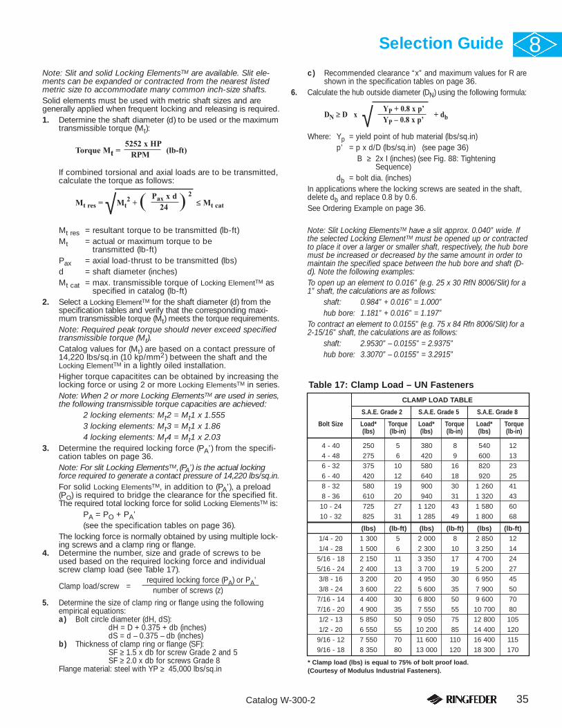
35Catalog W-300-2
Selection Guide 8Note: Slit and solid Locking ElementsTM are available. Slit ele-ments can be expanded or contracted from the nearest listedmetric size to accommodate many common inch-size shafts.Solid elements must be used with metric shaft sizes and aregenerally applied when frequent locking and releasing is required.1. Determine the shaft diameter (d) to be used or the maximum
transmissible torque (Mt):
Torque Mt = 5252 x HP
(lb-ft)RPM
If combined torsional and axial loads are to be transmitted,calculate the torque as follows:
Mt res = Mt2 + ( Pax x d ) 2
≤ Mt cat24
Mt res = resultant torque to be transmitted (lb-ft)Mt = actual or maximum torque to be
transmitted (lb-ft)Pax = axial load-thrust to be transmitted (lbs)d = shaft diameter (inches)Mt cat = max. transmissible torque of Locking ElementTM as
specified in catalog (lb-ft)2. Select a Locking ElementTM for the shaft diameter (d) from the
specification tables and verify that the corresponding maxi-mum transmissible torque (Mt) meets the torque requirements.Note: Required peak torque should never exceed specifiedtransmissible torque (Mt).Catalog values for (Mt) are based on a contact pressure of14,220 lbs/sq.in (10 kp/mm2) between the shaft and theLocking ElementTM in a lightly oiled installation.Higher torque capacitites can be obtained by increasing thelocking force or using 2 or more Locking ElementsTM in series.Note: When 2 or more Locking ElementsTM are used in series,the following transmissible torque capacities are achieved:
2 locking elements: Mt2 = Mt1 x 1.5553 locking elements: Mt3 = Mt1 x 1.86 4 locking elements: Mt4 = Mt1 x 2.03
3. Determine the required locking force (PA’) from the specifi-cation tables on page 36.Note: For slit Locking ElementsTM,(PA’) is the actual lockingforce required to generate a contact pressure of 14,220 lbs/sq.in.For solid Locking ElementsTM, in addition to (PA’), a preload(PO) is required to bridge the clearance for the specified fit.The required total locking force for solid Locking ElementsTM is:
PA = PO + PA’(see the specification tables on page 36).
The locking force is normally obtained by using multiple lock-ing screws and a clamp ring or flange.
4. Determine the number, size and grade of screws to beused based on the required locking force and individualscrew clamp load (see Table 17).
Clamp load/screw = required locking force (PA) or PA’
number of screws (z)
5. Determine the size of clamp ring or flange using the followingempirical equations:a) Bolt circle diameter (dH, dS):
dH = D + 0.375 + db (inches)dS = d – 0.375 – db (inches)
b) Thickness of clamp ring or flange (SF):SF ≥ 1.5 x db for screw Grade 2 and 5SF ≥ 2.0 x db for screws Grade 8
Flange material: steel with YP ≥ 45,000 lbs/sq.in
c) Recommended clearance “x” and maximum values for R areshown in the specification tables on page 36.
6. Calculate the hub outside diameter (DN) using the following formula:
DN ≥ D x YP + 0.8 x p’
+ dbYP – 0.8 x p’
Where: Yp = yield point of hub material (lbs/sq.in)p’ = p x d/D (lbs/sq.in) (see page 36)
B ≥ 2x I (inches) (see Fig. 88: TighteningSequence)
db = bolt dia. (inches)In applications where the locking screws are seated in the shaft,delete db and replace 0.8 by 0.6.See Ordering Example on page 36.
Note: Slit Locking ElementsTM have a slit approx. 0.040” wide. Ifthe selected Locking ElementTM must be opened up or contractedto place it over a larger or smaller shaft, respectively, the hub boremust be increased or decreased by the same amount in order tomaintain the specified space between the hub bore and shaft (D-d). Note the following examples:To open up an element to 0.016” (e.g. 25 x 30 RfN 8006/Slit) for a1” shaft, the calculations are as follows:
shaft: 0.984” + 0.016” = 1.000”hub bore: 1.181” + 0.016” = 1.197”
To contract an element to 0.0155” (e.g. 75 x 84 Rfn 8006/Slit) for a2-15/16” shaft, the calculations are as follows:
shaft: 2.9530” – 0.0155” = 2.9375”hub bore: 3.3070” – 0.0155” = 3.2915”
√
4 - 40 250 5 380 8 540 12
4 - 48 275 6 420 9 600 13
6 - 32 375 10 580 16 820 23
6 - 40 420 12 640 18 920 25
8 - 32 580 19 900 30 1 260 41
8 - 36 610 20 940 31 1 320 43
10 - 24 725 27 1 120 43 1 580 60
10 - 32 825 31 1 285 49 1 800 68
(lbs) (lb-ft) (lbs) (lb-ft) (lbs) (lb-ft)1/4 - 20 1 300 5 2 000 8 2 850 12
1/4 - 28 1 500 6 2 300 10 3 250 14
5/16 - 18 2 150 11 3 350 17 4 700 24
5/16 - 24 2 400 13 3 700 19 5 200 27
3/8 - 16 3 200 20 4 950 30 6 950 45
3/8 - 24 3 600 22 5 600 35 7 900 50
7/16 - 14 4 400 30 6 800 50 9 600 70
7/16 - 20 4 900 35 7 550 55 10 700 80
1/2 - 13 5 850 50 9 050 75 12 800 105
1/2 - 20 6 550 55 10 200 85 14 400 120
9/16 - 12 7 550 70 11 600 110 16 400 115
9/16 - 18 8 350 80 13 000 120 18 300 170
CLAMP LOAD TABLE
S.A.E. Grade 2 S.A.E. Grade 5 S.A.E. Grade 8
Bolt Size Load* Torque Load* Torque Load* Torque(lbs) (lb-in) (lbs) (lb-in) (lbs) (lb-in)
√
Table 17: Clamp Load – UN Fasteners
* Clamp load (lbs) is equal to 75% of bolt proof load.(Courtesy of Modulus Industrial Fasteners).

36 Catalog W-300-2
d = nominal inner ring I.D.= shaft O.D.
T1 = machining tolerances for shaft (d)Tb = machining tolerances for hub bore (d)D = nominal outer ring O.D.
= hub counter bore I.D.T2 = machining tolerances for hub counter bore (D)L, I = width dimensions, relaxed conditionPO = preload to bridge specified fit clearancesPA = actual locking force to generate p = 14,220 lbs/sq.inMt = transmissible torque of one locking elementp = contact pressure between inner ring and shaftx = recommended clearance between clamp flange and hub or shaftR = radius in hub outer bored1 = spacer sleeve I.D.
T3 = tolerances for spacer sleeve I.D. and O.D.D1 = spacer sleeve O.D.Pax = axial load capacity
= Mt x 24 lbs (for Mt in lb-ft)
dNote: Values for (Mt) are based on a contact pressure of 14,220 psi(10 kp/mm2) between the shaft and Locking ElementTM in a lightlyoiled installation and a coefficient of friction of µ = 0.12.
Clamp Flange
Fig. 86: Hub bolted design Fig. 87: Shaft bolted design
Ordering ExampleSize RfN Series-Type
Solid: 25 x 30 RfN 8006/ SOLIDSlit: 25 x 30 RfN 8006/ SLIT
RfN 8006 Locking ElementTM dimensions MtSize inches (based on
X R Spacer sleeved x D PO PA’
p=14220psi) 1 2 3 inchesmm d T1 Tb D T2 L I lbs lbs lb-ft Elements inches inches d1 T3 D1
6 x 9 .236 .354 – 0 .177 .146 — 713 1.56 .08 .08 .12 .004 .240 .3507 x 10 .276 .394 +.0006 .177 .146 — 832 2.13 .08 .08 .12 .004 .280 .3908 x 11 .315 +0 – 0 .433 .177 .146 — 946 2.78 .08 .08 .12 .004 .319 .4299 x 12 .354
–.0004 +.0006.473 .177 .146 1 672 1 254 4.12 .08 .08 .12 .004 .358 .468
10 x 13 .394 .512 – 0 .177 .146 1 529 1 386 5.06 .08 .08 .12 .004 .398 .50812 x 15 .473 .591 +.0007 .177 .146 1 529 1 650 7.23 .08 .08 .12 .004 .476 .58613 x 16 .512 .630 .177 .146 1 419 1 793 8.53 .08 .08 .12 .004 .516 .62614 x 18 .551 +0 – 0 .709 .248 .209 2 464 2 772 14.18 .12 .12 .16 .004 .555 .70515 x 19 .591 –.0004 +.0007 .748 .248 .209 2 365 2 970 16.27 .12 .12 .16 .004 .594 .74416 x 20 .630 .787 .248 .209 2 222 3 168 18.44 .12 .12 .16 .004 .634 .78317 x 21 .669 .827 .248 .209 2 101 3 366 20.90 .12 .12 .16 .004 .673 .82318 x 22 .709 .866 – 0 .248 .209 2 002 3 564 23.43 .12 .12 .16 .004 .712 .86219 x 24 .748 .945 +.0008 .248 .209 2 772 3 762 26.04 .12 .12 .16 .004 .756 .93720 x 25 .787 .984 .248 .209 2 561 3 960 28.93 .12 .12 .16 .004 .795 .97622 x 26 .866 +0 – 0 1.024 .248 .209 1 991 4 356 34.72 .12 .12 .16 .004 .874 1.01524 x 28 .945 –.0005 +.0008 1.102 .248 .209 1 837 4 752 41.95 .12 .12 .16 .004 .952 1.09425 x 30 .984 1.181 .248 .209 2 178 4 950 44.84 .12 .12 .16 .004 .992 1.17328 x 32 1.102 1.260 .248 .209 1 628 5 544 56.42 .12 .12 .16 .004 1.110 1.25230 x 35 1.181 1.378 .248 .209 1 870 5 940 65.10 .12 .12 .16 .004 1.189 1.37032 x 36 1.260 1.417 .248 .209 1 727 6 336 73.78 .12 .12 .16 .004 1.268 1.40935 x 40 1.378 1.575 – 0 .276 .236 2 222 7 832 99.82 .12 .12 .16 .004 1.386 1.56736 x 42 1.417 1.654 +.001 .276 .236 2 552 8 052 106.33 .12 .12 .16 .004 1.425 1.64538 x 44 1.4986 +0 – 0 1.732 .276 .236 2 420 8 514 117.90 .12 .12 .16 .004 1.504 1.72440 x 45 1.575 –.0006 +.001 1.772 .315 .260 3 036 9 900 143.94 .12 .16 .20 .004 1.583 1.76442 x 48 1.654 1.890 .315 .260 3 432 10 340 158.40 .12 .16 .20 .004 1.661 1.88245 x 52 1.772 2.047 .394 .339 6 204 14 520 237.24 .12 .16 .20 .008 1.779 2.03948 x 55 1.890 2.165 .394 .339 5 412 15 400 269.79 .12 .16 .20 .008 1.897 2.15750 x 57 1.969 2.244 .394 .339 5 170 16 060 292.94 .12 .16 .20 .008 1.976 2.23655 x 62 2.165 2.441 .394 .339 4 796 17 600 354.42 .12 .16 .20 .008 2.173 2.43356 x 64 2.205 2.520 – 0 .472 .409 6 468 21 780 444.83 .12 .16 .20 .008 2.212 2.51260 x 68 2.362 2.677 +.0018 .472 .409 6 028 23 320 509.93 .12 .16 .20 .008 2.370 2.66963 x 71 2.480 +0 – 0 2.795 .472 .409 5 786 24 420 564.17 .12 .16 .20 .008 2.488 2.78765 x 73 2.559 –.0018 +.0018 2.874 .472 .409 5 580 25 300 600.34 .12 .16 .20 .008 2.567 2.86670 x 79 2.756 3.110 .551 .480 6 820 31 900 810.10 .12 .20 .24 .012 2.768 3.09871 x 80 2.795 3.150 .551 .480 6 820 32 340 839.03 .12 .20 .24 .012 2.807 3.13775 x 84 2.953 3.307 .551 .480 7 612 34 100 933.06 .12 .20 .24 .012 2.964 3.29580 x 91 3.150 3.583 .669 .591 10 560 44 660 1 309.17 .16 .20 .24 .012 3.161 3.57085 x 96 3.346 3.780 – 0 .669 .591 10 032 47 520 1 475.53 .16 .20 .24 .012 3.358 3.76790 x 101 3.543 3.976 +.0022 .669 .591 9 548 50 380 1 656.36 .16 .20 .24 .012 3.555 3.96495 x 10⁶ 3.740 +0 – 0 4.173 .669 .591 9 064 53 240 1 844.42 .16 .20 .24 .012 3.752 4.161
100 x 114 3.937 –.0022 +.0022 4.488 .827 .736 13 354 69 740 2 546.02 .16 .24 .28 .016 3.949 4.476110 x 124 4.331 4.882 .827 .736 14 520 76 780 3 074.03 .16 .24 .28 .016 4.342 4.870120 x 134 4.724 5.276 – 0 .827 .736 13 244 83 600 3 652.67 .16 .24 .28 .016 4.736 5.263130 x 148 5.118 +0 – 0 5.827 +.0025 1.102 .996 21 164 122 760 5 822.57 .20 .28 .35 .016 5.134 5.811140 x 158 5.512 –.0025 +.0025 6.220 1.102 .996 19 580 132 000 6 762.86 .20 .28 .35 .016 5.527 6.204150 x 168 5.906 6.614 1.102 .996 18 590 141 460 7 739.31 .20 .28 .35 .016 5.921 6.598
±.0
02±
.001
5±
.001
Table 18: Locking ElementsTM RfN 8006Material: Special Spring Steel*
* Stainless steel available upon request.For larger sizes up to shaft diameters of 1000 mm (39.37”), see Catalog S86A.
8 Locking ElementsTM RfN 8006 Specifications

37Catalog W-300-2
Clamp Plate Design Criteria 8Mounting — There are two basic methods for mounting theclamp plate:
1. Hub bolting permits axial positioning of the hub as well asangular adjustment.
2. Shaft bolting requires the hub to be backed against a shoul-der to support the clamping force. This method does notallow axial adjustment.
Bolt Circle Diameter (dH or dS) — This method permitsthe locking screws to be as close as possible to the Locking ElementsTM.
Note: If a single locking screw or nut is located in the center of theshaft it must be secured to prevent loosening.
Thickness (SF) — Thickness must be sufficient to preventexcessive deflection under the required locking force.Deflection will reduce the induced axial locking force onthe elements and may cause the plate to bottom out on the hubor shaft face.
Clearance — Under full applied force, there must be an axialclearance between the clamp plate and hub or shaft face toprevent bottoming out. A spacer sleeve may be necessary. The sleeve outer diameter must be smaller than the hubcounter bore by approx. 0.005”, and its inner diameter must be larger than the shaft diameter by the same amount toassure a clearance fit.
Hub Outside Diameter (DN) — The outside diameter ofthe hub must be sized to accommodate radial contactpressures.
Installation and Removal InstructionsSince the torque is transmitted by contact pressure and frictionbetween the frictional surfaces, the condition of the contactsurfaces and the proper tightening of the locking screws areimportant.
INSTALLATION
1. Carefully clean and lightly oil the shaft, hub bore, spacersleeves and Locking ElementsTM.
Note: Do NOT use a Molybdenum Disulphide LUBRICANT (“MOLYKOTE” OR THE LIKE).
2. Install the parts in the following order:a) Hub (the play between hub bore and shaft affects the
true running of the hub).b) Spacer sleeve to bridge the undercut (if needed)c) Outer ring/inner ring (both parts must slide on easily).
For one Locking ElementTM install the outer ring first.Otherwise, install the inner ring first.
d) Spacer sleeve and clamp flange or clamp ring (bothparts should slide on easily).
e) Carefully oil the locking screw threads and head bear-ing surfaces.
Note: Do NOT use Molybdenum Disulphide.
3. Tighten the locking screws evenly and in several steps fol-lowing the diametrically opposite sequence illustrated inFig. 88.a) Tighten the screws by hand until a slight positive con-
tact is established. Make final alignment adjustments tothe connection.
b) Tighten the screws to approx. one-half the specifiedtorque using an extended key or torque wrench.
c) Tighten the screws to full tightening torque using atorque wrench.
d) Verify that the screws are fully tightened by applyingthe specified torque.
4. Check distance x. The clamp ring should not make contactwith the face of the hub. The gap between the clamp ringand hub face should be even all the way around.
REMOVALNote: Ringfeder® Locking ElementsTM are not self-locking.
1. Remove any accumulated contaminants from the connection.
2. Loosen the locking screws in several stages following a dia-metrically opposite sequence.
3. Reduce the hub and Locking ElementsTM from the shaft. Ifthe Locking ElementTM is jammed, loosen it by tapping it witha light hammer.
Hub
Shaft
Fig. 88: Tightening SequenceTightening sequence for locking screws.

38 Catalog W-300-2
Locking ElementsTM GSA Specifications
Clearance
HubSpacer Sleeve
Fig. 89: Hub bolted Clamp Plate(hub axially adjustable)
Fig. 90: Shaft bolted Clamp Plate(hub axially fixed)
d = shaft diameterT1 = machining tolerances for shaft (d)D = counter bore diameterT2 = machining tolerances for counter bore (D)L, I = width dimensions, relaxed conditionR = radius in hub borePO = preload to bridge specified fit clearancesPA = actual locking force to generate Mt
Mt = transmissible torque for one Locking ElementTM based on coeffi-cient of friction of µ = 0.15 and 10,000 psi contact pressure(torque can be increased by up to 50%)
Pax = axial load (thrust capacity)
= Mt x 24 lbs (for Mt lb-ft)
dW
Selection Guide1. Determine the shaft diameter to be used and the maximum
torque (T) to be transmitted.
T = 63,000 x HP
(inch-lbs)RPM
2. Select a locking element from the specification table for the shaftdiameter. Verify that the transmissible torque (Mt) for the elementmeets the torque requirement.
Note: Required peak torque should never exceed specified trans-missible torque (Mt). Higher torque capacitites can be obtained byincreasing the locking force.
3. Determine the required locking force (PA’) from Table 19. A pre-load (PO) is required to bridge the clearance for the specified fits.The total required locking force is PA = PO + PA’.
The locking force is normally obtained by using one or morescrews and a clamp plate (see Fig. 80 and Fig. 81).
4. Refer to Table 16: Clamp Load on page 33 to determine the num-ber, size and grade of screws needed for the required lockingforce and individual screw clamp load.
Clamp load/screw = required locking force (PA) of PA’
number of screws (z)
GSA–250 .250 .375 .126 .094 580 450 14 .76GSA–312 .3125 +0 .4375 -0 .143 .112 686 670 26 1.04GSA–375 .375 –.0005 .500 +.0005 .160 .128 673 920 43 1.35GSA–437 .4375 .5937 .176 .143 796 1 196 65 2.20GSA–500 .500 .6562 .193 .158 944 1 512 94 2.69
*GSA–562 .5625 .750 –0 .210 .174 1 259 1 872 132 3.97GSA–625 .625 .8125
+.001.226 .187 1 231 2 237 175 4.69
*GSA–687 .6875 .875 .243 .203 1 414 2 670 230 5.47GSA–750 .750 +0 .9375 .260 .219 1 413 3 145 295 6.33GSA–812 .8125 –.001 1.0312 .276 .234 1 617 3 637 370 8.56GSA–875 .875 1.0937 –0 .293 .250 1 611 4 188 458 10.14
*GSA–937 .9375 1.1875 +.0015 .310 .267 2 087 4 790 561 12.36GSA–1000 1.000 1.250 .326 .284 2 090 5 437 680 14.05GSA–1125 1.125 +0 1.406 .359 .312 2 220 6 620 840 19.55GSA–1250 1.250 –.0015 1.531 .393 .344 2 240 8 105 1 140 23.54GSA–1375 1.375 1.687 .426 .376 2 745 9 750 1 510 31.22GSA–1500 1.500 +0 1.812 –0 .459 .407 3 030 11 510 1 940 36.38GSA–1625 1.625 –.002 1.968 +.002 .492 .437 3 295 13 390 2 450 46.43GSA–1750 1.750 2.125 .526 .469 3 585 15 475 3 045 58.53GSA–1875 1.875 2.250 .559 .500 3 595 17 675 3 730 66.22
*GSA–2000 2.000 2.406 .592 .528 5 365 19 910 4 480 81.09*GSA–2250 2.250 2.656 .592 .528 4 795 22 400 5 670 90.30GSA–2437 2.437 +0 2.843 –0 .592 .528 4 430 24 260 6 655 97.07
*GSA–2500 2.500 –.003 2.906 +.003 .592 .528 4 330 24 885 7 000 99.50GSA–2687 2.687 3.093 .592 .528 4 035 26 750 8 090 106.26
*GSA–2750 2.750 3.156 .592 .528 3 950 27 370 8 470 108.70*GSA–3000 3.000 3.406 .592 .528 3 890 29 860 10 080 117.90
GSA Locking ElementTM dimensionsWt.
Size d T1 D T2 L I PO PA’ Mt lbs perinches lbs lbs lb-in 1000
Table 19: Locking ElementsTM Type GSAMaterial: Aluminum Alloy*
* Stainless steel available upon request.* Delivery on request; other sizes stocked. Contact Ringfeder Corporation for additional sizes and information.
8

For controlled tightening of locking screws of LockingAssembliesTM RINGFEDER®, we offer suitable torquewrenches and attachments. These tools facilitate theinstallation of our Locking AssembliesTM RfN 7012 partic-ularly on straight through shafts. They can be used, ofcourse, also for mounting of Locking AssembliesTM
RINGFEDER® RfN 7013, 7014, 7015, Locking ElementsTM
RINGFEDER® RfN 8006 and Shrink Discs® RfN 4071,RfN 4051 and RfN 4091.
The rigid square drives SD and hex bit sockets exhibitcompact over-all dimensions and can be combined withcommercially available extensions. The SD-drives fit withall CCM torque handles. Square drives and hex bit sock-et drives required for any given Locking AssemblyTM sizeare listed in the following table.
Description and operationWhen preset torque is reached, you hear a click and feelthe breakover. No inaccuracies are caused by dials andindicators.
Torque setting is achieved by turning the adjustablemicrometer torque handle. Every setting point is felt by a distinct stop.
Torque setting cannot accidentally change while wrenchis in use. By turning the lock screw located at the end ofthe handle counter-clockwise (“Lock”), the adjustablehandle is locked. By turning it clockwise (“Unlock”), thehandle is unlocked.
Frictionless adjustment mechanism permits high torqueaccuracy even after prolonged use.
Slim design and light weight for better accessibility tofasteners and minimum operator fatigue.
Required attachments slide easily onto the dovetailedand pin locked torque handle. For release of attach-ments, the spring-loaded lock pin can be easilydepressed by a pin or screw driver.
39Catalog W-300-2
Fig. 91: Square Drives1/4”, 3/8”, 1/2” or 3/4” square drive
Fig. 92
Fig. 93
9Torque Wrenches
Torque wrenches are an integral part of the proper installation of all Ringfeder ®
locking devices. We, therefore, offer a low profile head torque wrench specificallysuited to our products.
MAX.PART MODEL DRIVE TORQUE A B C D E
NUMBER NUMBER SIZE in lbs in. in. in. in. in.819057 SD-1/4 1/4 250 1-23/32 9/16 -3/4 3/4 -11/16819058 SD-3/8 3/8 1250 1-7/8 7/8 -7/8 1-1/8 -13/16819059 SD-1/2 1/2 2500 1-7/8 7/8 1- 1-1/8 -13/16819119 SD-3/4* 3/4 4800 4-5/8 1-1/2 1-13/32 1-1/2 1-
Table 20: SQUARE DRIVE ENGLISH
Various accessoriesare available upon
request. Call our technical department
for assistance.
RINGFEDER Products are available from MARYLAND METRICSP.O. Box 261 Owings Mills, MD 21117 USA email: [email protected] web: http://mdmetric.com
phones: (410)358-3130 (800)638-1830 faxes: (410)358-3142 (800)872-9329
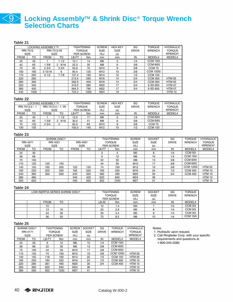
®
®
®
40 Catalog W-300-2
9 Locking AssemblyTM & Shrink Disc® Torque WrenchSelection Charts
Table 21
Table 22
Table 23
Table 24
Table 25
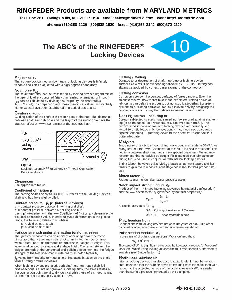
41Catalog W-300-2
10The ABC’s of the RINGFEDER®
Locking Devices
AdjustablilityThe friction-lock connection by means of locking devices is infinitelyvariable and can be adjusted with a high degree of accuracy.
Axial force FaxThe axial thrust that can be transmitted by locking devices regardless ofthe type of load encountered (static, increasing, alternating or impact).Fax can be calculated by dividing the torque by the shaft radius (Fax = 2 x t/d). In comparison with these theoretical values, substantiallyhigher values have been established in practical operations.
Centering actionGuiding action of the shaft in the minor bore of the hub. The clearancebetween shaft and hub bore and the length of the minor bore have thegreatest effect on True running of the mounted hub.
ClearancesSee appropriate tables.
Coefficient of friction µThe catalog values apply to µ = 0.12. Surfaces of the Locking Devices,shaft and hub bore slightly oiled.
Contact pressure p, p’ (internal devices)p = contact pressure between inner ring and shaftp’ = contact pressure between outer ring and hubp and p’ – together with the Coefficient of friction µ – determine thefrictional connection value. In order to avoid deformation in the plasticrange, the following values must obtain:
p < yield point at shaftp’ < yield point of hub
Fatigue strength under alternating torsion stressesThe greatest variable stress component oscillating about the meanstress zero that a specimen can resist an unlimited number of timeswithout fracture or inadmissable deformation is Fatigue Strength. Thisvalue is influenced by shape and surface finish. The ratio between thefatigue strength of the unnotched and polished specimen and the fatiguestrength of the test specimen is referred to as notch factor ßk.
ßk varies from material to material and decreases in value as the statictensile strength value increases.
When locking devices are used, both shaft and hub retain their fullcross-sections, i.e. are not grooved. Consequently, the stress states atthe connection point are virtually identical with those of a smooth shaft,i.e. the material is utilized by almost 100%.
Fretting / GallingDamage to or destruction of shaft, hub bore or locking device surfaces as a result of overloading followed by Slip. Fretting canalways be avoided by correct dimensioning of the connection.
Fretting corrosionCorrosion between the contact surfaces of ferrous metals. Even thesmallest relative movements favour and accelerate fretting corrosion;lubricants can delay the process, but not stop it altogether. Long-termprevention of fretting corrosion can be achieved only by designing theconnection in such a way that relative movement is impossible.
Locking screws – securing ofScrews subjected to static loads need not be secured against slacken-ing (in some cases, lock washers, etc. can even be harmful). Thescrews used in conjunction with locking devices are normally sub- jected to static loads only: consequently, they need not be securedagainst loosening. Tightening down to the specified torque value isquite adequate.
MolykoteTrade name of a lubricant containing molybdenum disulphide (MoS2). AsMoS2 reduces the Coefficient of friction, it is used for frictional con-nections between shafts and hubs in exceptional cases only. We urgentlyrecommend that our advice be sought if it is intended that lubricants con-taining MoS2 be used in conjunction with internal locking devices.
Shrink Discs®, however, utilize MoS2 greases to lubricate tapers and fas-teners to gain the mechanical advantage necessary for their proper func-tion.
Notch factor ßkFatigue strength under alternating torsion stresses.
Notch impact strength figure �kProduct of the Shape factor �k (governed by material configuration)and the Notch factor ßk (governed by material properties):
ßk – 1�k =
�k – 1
Approximate values for �k:
0,4 ... 0,8 – light metals and C-steels
0,6 ... 1 – heat-treatable steels
Play, freedom fromConnections with locking devices are absolutely free of play. Like otherfrictional connections there is no danger of lateral oscillation.
Polar section modulus WpIn the case of circular cross sections, Wp is defined thus:
Wp = d3 x π/16
The value of Wp is significantly reduced by keyways, grooves for Woodruffkeys, etc. When using locking devices the full cross-section of the shaft isavailable (see Shape factor �k).
Radial load, admissableInternal locking devices can also absorb radial loads. It must be consid-ered, however, that the surface pressure resulting from the radial load withrespect to the projected surface of the Locking AssemblyTM, is smallerthan the surface pressure generated by the clamping.
Fig. 94Locking AssemblyTM RINGFEDER® 7012 Connection.Principle sketch.
RINGFEDER Products are available from MARYLAND METRICSP.O. Box 261 Owings Mills, MD 21117 USA email: [email protected] web: http://mdmetric.com
phones: (410)358-3130 (800)638-1830 faxes: (410)358-3142 (800)872-9329

42 Catalog W-300-2
The ABC’s of Locking Devices, continued10ReleasabilityLocking AssembliesTM RfN 7012 and Locking Elements 8006 are not self-locking. The angle of the tapered rings is such that releasability is guaran-teed even after prolonged heavy loading. Extractors are not required.
RustBecause of the relatively high pressures per unit of area, rusting cannottake place between the effective surfaces of a locking device as well asshaft and hub. Some locking devices have split inner and outer rings andcannot hermetically seal the clamping point. In this case we advise to usecorrosion inhibitors, seals, etc. in order to protect the LockingAssembliesTM (locking screws) against corrosion.
SafetyThe frictional connection values given in the tables are achieved or evenexceeded if designing is correct and the connection properly made. Thetheoretical values are higher. Frictional connections of all types – includ-ing shrink fits and press fits – must be designed in such a way that theload peaks can be dependably transmitted. However, the load peaksvary so greatly from case to case that we are unable to give any recom-mendations as regards specific safety factors.locking device connections are insensitive to impact loads (see Fig. 95).
Shape factor �kProportional factor covering stress conditions at bores, cross-sectionstransitions, clamping points, grooves, etc. The following applies:
�max maximum stress�k = �n
= nominal stress
(use smallest cross-sections and/or resistance moments when determin-ing �n).
For smooth shafts �k = 1.
SlipAll shrink fits slip when overloading takes place. Fretting of thecontact (slipping) surfaces is normally unavoidable. Locking AssembliesTM
subjected to high pressures per unit of area and rotating at high periph-eral speeds can be completely destroyed. Under normal circumstances,the degree and type of destruction do not indicate the cause of slipping.
Slipping clutchLocking devices are not suitable for use as a slipping clutch withoutconsulting us.
Tangential stressesTensile stress in the hub bore or compression stress in the bore of hol-low shafts as a result of the Contact pressures between outer lock-ing ring and hub and/or inner locking ring and hollow shaft.
Temperature, influence ofShrink fits – and thus locking device connections, too – give perfect service as long as the contact pressure in the joint does not drop belowa certain minimum value. Consequently, contact pressure in the joint atoperating temperature must be the subject of close attention. Pleasecontact us for advice.
Torque wrenchStandard tool indicating the tightening torque exerted on the screwheads. All Ringfeder® locking devices require a torque wrench for properinstallation.
True runningThe relatively narrow Locking AssembliesTM RINGFEDER® RfN 7012serve mainly to transmit high torques and axial forces. They are not self-centering. True running of the hub/boss is thus governed by theCentering action and the care taken during Fitting.
Fig. 95
Fig. 96Influence of the groove shape on shape factor �k andthus on the Polar moment of resistance; extractfrom the work of Prof. Thum.
Fig. 97Tangential stresses in shrink fits.
Fig. 98Pre-centering by selection of correct fit betweenshaft and hub.
NOTE: DO NOT USE IMPACT WRENCH TO INSTALLRINGFEDER® LOCKING DEVICES!
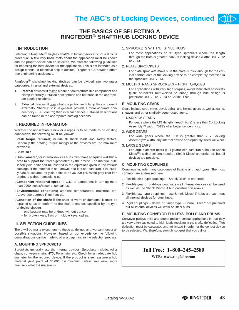
43Catalog W-300-2
The ABC’s of Locking Devices, continued 10
I. INTRODUCTIONSelecting a Ringfeder® keyless shaft/hub locking device is not a difficultprocedure. A few very basic facts about the application must be knownand the proper device can be selected. We offer the following guidelinesfor choosing the best device for the application. This is not intended as adesign manual. If technical help is desired, Ringfeder Corporation offersfree engineering assistance.
Ringfeder® shaft/hub locking devices can be divided into two major categories; internal and external devices.
1. Internal devices fit inside a bore or counterbore in a component andclamp internally. Detailed descriptions can be found in the appropri-ate catalog sections.
2. External devices fit over a hub projection and clamp the componentexternally. Shrink Discs® in general, provide a more accurate con-centricity (T.I.R. control) than internal devices. Detailed descriptionscan be found in the appropriate catalog sections.
II. REQUIRED INFORMATIONWhether the application is new or a repair is to be made to an existingconnection, the following must be known:
* Peak torque required; include all shock loads and safety factors.Generally the catalog torque ratings of the devices are the maximumallowable.
* Shaft size
* Hub diameter; for internal devices hubs must have adequate wall thick-ness to support the forces generated by the device. The material pub-lished yield point can be inserted in the equations given in the variouscatalogs. If the material is not known, and it is not cast iron, it is usual-ly safe to assume the yield point to be 36,000 psi. Avoid grey cast ironproducts without consulting us.
* Component rotational speed; if O.D. of component is turning morethan 2000 inches/second, consult us.
* Environmental conditions; ambient temperatures, moisture, etc.Above 400 degrees F, contact us.
* Condition of the shaft; if the shaft is worn or damaged it must berepaired so as to conform to the shaft tolerances specified by the typeof device chosen.
– one keyseat may be bridged without concern.– for broken keys, flats or multiple keys, call us.
III. SELECTION GUIDELINESThere will be many exceptions to these guidelines and we can’t cover allpossible situations. However, based on our experience the following generalizations can be made to offer a beginning in the selection process.
A. MOUNTING SPROCKETSSprockets generally use the internal devices. Sprockets include: rollerchain, conveyor chain, HTD, Polychain, etc. Check for an adequate hubdiameter for the required device. If the product is steel, assume a hubmaterial yield point of 36,000 psi minimum unless you know more precisely what the material is.
1. SPROCKETS WITH ‘B’ STYLE HUBSFor most applications on ‘B’ type sprockets where the lengththrough the bore is greater than 2 x locking device width; USE 7012or 7013.
2. PLATE SPROCKETSFor plate sprockets make sure the plate is thick enough for the crit-ical contact area of the locking device to be completely recessed inthe sprocket; USE 7013.
3. MULTI-STRAND SPROCKETS – HIGH TORQUESFor applications with very high torques, avoid laminated sprockets(plate sprockets butt-welded to hubs); through hub design is preferred; USE 7012, 7013 or Shrink Disc® .
B. MOUNTING GEARSGears include spur, miter, bevel, spiral, and helical gears as well as cams,sheaves and other similarly constructed items.
1. NARROW GEARSFor gears where the LTB (length through bore) is less than 2 x LockingAssemblyTM width, 7013’s offer better concentricity.
2. WIDE GEARSFor wide gears where the LTB is greater than 2 x LockingAssemblyTM width, any internal device appropriately sized will work.
3. LARGE GEARSFor large diameter gears (bull gears) with cast iron hubs use ShrinkDiscsTM; with steel construction, Shrink Discs® are preferred, but alldevices are possible.
C. MOUNTING COUPLINGSCouplings include many categories of flexible and rigid types. The mostcommon are addressed here.
1. Flexible disk-type couplings – Shrink Disc® is preferred.
2. Flexible gear or grid-type couplings – all internal devices can be usedas well as the Shrink Discs® if hub construction allows.
3. Flexible jaw-type couplings – use Shrink Discs® if hubs are cast iron; all internal devices for steel hubs.
4. Rigid couplings – sleeve or flange type – Shrink DiscsTM are preferredbut all internal devices will work on steel hubs.
D. MOUNTING CONVEYOR PULLEYS, ROLLS AND DRUMSConveyor pulleys, rolls and drums present unique applications in that theyare very often subjected to high loads resulting in the shafts deflecting. Thisdeflection must be calculated and minimized in order for the correct deviceto be selected. We, therefore, strongly suggest that you call us!
Toll Free: 1–800–245–2580WEB: www.ringfeder.com
THE BASICS OF SELECTING A RINGFEDER® SHAFT/HUB LOCKING DEVICE

RFC SPECIALTY PRODUCTS
In accordance with our established policy to constantly improve our products, the specifications contained herein are subject to change without notice.
Since our Engineers cannot be aware of all applications and cannot control all the factors that may affect the function of our products, our warranty applies toour products only.
TECHNICAL ASSISTANCECall us Toll Free at 1–800–638-1830
Please let us know what your specific requirements are andwe shall be very happy to work out detailed recommenda-tions without any obligation. Just send a sketch with yourrequirements and specifications.
Call or write for more information.Visit our website: www.mdmetric.com
© Copyright 2001, 2005 W–300-2 11/01 GP Printed in U.S.A.
RING-flex® Single Flexing andDouble Flexing Couplings withRingfeder® Shrink Discs®
Assure a totally backlash-free connec-tion with precise synchronization capa-bility. Additional features: Clearance fitsfor hub/shaft connection allow easyassembly and free axial movementcompensation during installation whicheliminates unwanted pre-loading or pre-stressing of the flexible elements.
ARCUSAFLEX® FlywheelCouplingsHighly flexible, backlash-free, vulcanizedrubber disc couplings designed to cou-ple the flywheel of an internal combus-tion engine to the shaft of the drivenmachine. Rubber disc element acceptsrelatively high angular, axial and parallelmisalignments. Flange dimensionsaccording to SAE J620 standards.
Multi Mont OCTA FlywheelCouplingsTorsionally flexible, economical flangecouplings for connecting the flywheel ofa combustion engine to the input shaftof a driven machine. Rubber elementsdampen vibrations and accommodatemisalignments.
RFC Specialty Locking DevicesRingfeder Corporation excels at special-ty keyless shaft/hub connection solu-tions. From 1/4” shafts to 30” shafts,our engineers have the solution.
BALL DETENT TORQUE LIMITERS Type BDThese accurate ball/roller and sockettorque limiters are easily adjustable fordifferent torque settings. In the event ofan overload, personnel and equipmentare protected as these devices discon-nect mechanically and make contactwith a limit switch that sounds andalarm or otherwise shuts the drivedown. Available in various configura-tions and combinations with couplings.
FRICTION TORQUE LIMITERType FCEasily adjustable, these torque limitersrely on friction to transmit the set torque.When an overload occurs, these devicesslip until the overload is removed or themachine is reset. Available in variousconfigurations and combinations withcouplings.
RINGFEDER Products are available from MARYLAND METRICSP.O. Box 261 Owings Mills, MD 21117 USA email: [email protected] web: http://mdmetric.com
phones: (410)358-3130 (800)638-1830 faxes: (410)358-3142 (800)872-9329