Ring Mold Tutorial
56
Copyright © 2006 MecSoft Corporation. i RhinoCAM & VisualMill Mold making Tutorial Machining a Ring Mold Copyright © 2006 MecSoft Corporation All rights reserved. Rhinoceros is a registered trademark and Rhino is a trademark of Robert McNeel & Associates. RhinoCAM & VisualMill are registered trademarks of MecSoft Corporation.
-
Upload
pablo-horna-ramirez -
Category
Documents
-
view
13 -
download
4
Transcript of Ring Mold Tutorial

Copyright © 2006 MecSoft Corporation. i
RhinoCAM & VisualMill Mold making Tutorial
Machining a Ring Mold
Copyright © 2006 MecSoft Corporation All rights reserved.
Rhinoceros is a registered trademark and Rhino is a trademark of Robert McNeel & Associates.
RhinoCAM & VisualMill are registered trademarks of MecSoft Corporation.
Copyright © 2006 MecSoft Corporation. ii
Table of Contents 1. Introduction.......................................................................................................2
Strategy to Machine the Ring Mold......................................................................... 2 Main Programming Steps...................................................................................... 2
2. Creating the Programs for Bottom half of the mold............................................3 Load and Locate Part ........................................................................................... 3 Create Stock Model ............................................................................................. 4 Create the tools for machining this mold................................................................. 5
Save Tool library ........................................................................................... 5 Set Feeds & Speeds............................................................................................. 6 Set Clearance plane............................................................................................. 7 Create Horizontal Roughing operation. ................................................................... 7
Display Generated Toolpath........................................................................... 11 Simulate Horizontal roughing operation........................................................... 13
Create Facing operation ............................................Error! Bookmark not defined. Display Generated Toolpath..................................Error! Bookmark not defined. Simulate facing operation ....................................Error! Bookmark not defined.
Create Finishing operations................................................................................. 13 Select the regions for parallel finishing ................................................................. 14 Create the Machining Operation........................................................................... 15
Display Generated Toolpath........................................................................... 17 Simulate parallel finishing operation ............................................................... 17
Select the region for Second and Third parallel finishing.......................................... 18 Create the Machining Operation........................................................................... 19
Display Generated Toolpath........................................................................... 20 Simulate parallel finishing operation ............................................................... 21 Display Generated Toolpath........................................................................... 22 Simulate parallel finishing operation ............................................................... 23
Create Radial Machining operation ....................................................................... 24 Select the regions for radial machining ................................................................. 24 Create the Machining Operation........................................................................... 25
Display Generated Toolpath........................................................................... 27 Simulate radial machining operation ............................................................... 27
3. Post-Processing the Programs .........................................................................29 4. Creating the Programs for Top half of the mold ...............................................30
Load and Locate Part ......................................................................................... 30 Create Stock Model ........................................................................................... 31
Load Tool Library ......................................................................................... 32

Copyright © 2006 MecSoft Corporation. iii
Create Horizontal Roughing operation. ................................................................. 32 Display the generated tool path ..................................................................... 34 Simulate Horizontal Roughing operation .......................................................... 34
Create Facing operation ..................................................................................... 35 Display the generated tool path ..................................................................... 35 Simulate Facing operation............................................................................. 35
Create Slot Roughing operation ........................................................................... 36 Select the regions for Slot Roughing ............................................................... 37
Create the Machining Operation........................................................................... 38 Display the generated tool path ..................................................................... 40 Simulate Slot Roughing operation .................................................................. 40
Create Slot Finishing operation............................................................................ 41 Select the region for Slot Finishing ................................................................. 41
Create the Machining Operation........................................................................... 42 Display the generated tool path ..................................................................... 42 Simulate Slot Finishing operation ................................................................... 43
Create Horizontal Finishing operation ................................................................... 43 Select the region for Horizontal Finishing......................................................... 44
Create the Machining Operation........................................................................... 45 Display the generated tool path ..................................................................... 45 Simulate Horizontal Finishing operation........................................................... 46
Create Radial machining operation....................................................................... 47 Select the regions for radial machining ........................................................... 47
Create the Machining Operation........................................................................... 48 Display the generated tool path ..................................................................... 48 Simulate Radial machining operation .............................................................. 49
5. Post-Processing the Programs .........................................................................51 6. Machining the Ring Mold on Techno machine ...................................................52
Tool setup........................................................................................................ 52 Secure the Stock on to the table.......................................................................... 52 Setting Machine Zero......................................................................................... 52 Checking Machine Zero ...................................................................................... 53 Load the file, Pre-process and Preview ................................................................. 54 Completed Part ................................................................................................. 54
Copyright © 2006 MecSoft Corporation 2
1. Introduction
At this point of the tutorial you have created the Ring Mold.3DM or Ring Mold.vmp file and planning to machine this part using RhinoCAM or VisualMill.
This tutorial will illustrate machining this Ring Mold using 3 axis-milling operations.
This tutorial will introduce the usage of several 3 axis operations such as Horizontal roughing, parallel finishing and Radial machining.
Strategy to Machine the Ring Mold We will machine the Ring Mold completely using 3 axis operations.
The part itself will be machined out of a 2 x 2 inch x ½ inch wax
The stock may be held to the machine table or the spoil sheet on the table using double-sided tape or by clamps. This tutorial explains the use of tabs to hold the part while machining. The tabs are broken off after the machining operation is complete.
Tools used for machining this parts are ¼ inch flat end mill, and 1/8 inch and 1/16 inch ball mill.
The machine tool used will be a Techno-Isel DaVinci servo controlled router.
Main Programming Steps In creating programs for each setup, the following steps will be followed:
• Set the Machine zero point or Locate geometry with respect to the machine coordinates
• Create / Select the tool used for machining
• Set the feeds and speeds
• Set the clearance plane for the non-cutting transfer moves of the cutter
• Select the machining regions for containing the cutter to specific areas to cut
• Select the machining operations and set the parameters
• Generate the toolpath
• Simulate the toolpath.
You may have to repeat either all or part of these steps for subsequent operations.

Copyright © 2006 MecSoft Corporation 3
2. Creating the Programs for Bottom half of the mold
Load and Locate Part 1. First load the file Ring Mold Bottom.3dm or Ring Mold
Bottom.vmp
2. In the browser, select the Setup tab and pick the Locate Geometry button. Select the options shown in the dialog and select the OK button.
Once this step is performed the model will be moved such that the world coordinate zero is position at the lowest face and the lower left corner of the 3D model. In this exercise we will use the world coordinate zero point as the zero point of the machine tool.

Copyright © 2006 MecSoft Corporation 4
Create Stock Model
1. On the Setup tab in the browser click (create/ load stock) button in the toolbar and select Box Stock option
2. Select the settings shown and also enter the numbers shown in the dialog and select the OK button.
3. Click on the Stock tab on the browser to see the stock you just created.
Once this step is performed the stock model is created and positioned such that the world coordinate zero is at the top left corner of the stock model and also aligned with the lowest Z face of the stock model.
Note: Remember this setting will be used again while setting up the machine zero
This dialog box may appear different in the earlier versions of VisualMill.

Copyright © 2006 MecSoft Corporation 5
Create the tools for machining this mold
1. Select the Tools tab in the browser window and click on (Create tool) button in the toolbar. In the dialog box enter Diameter = 0.25, Flute length = 0.75, Tool length = 2.5
2. Name the tool as FlatMill1 and select the Save as New Tool button
Repeat the step to create 1/8-inch flat mill (Tool # 2) and 1/16-inch ball mill (tool#3). Make sure the tool numbers are in the order in which the tools will be used in machining.
Save Tool library
We will use these same tools for machining the top half of the mold. It will be easier to

Copyright © 2006 MecSoft Corporation 6
Save these tools and reuse them later. To do this select the save tool library Icon from the tools tab and save the file as RingMold.CSV. Icon appears as shown below
Set Feeds & Speeds
1. Select the Mops tab in the browser and click on (Set Feeds and Speeds) button in the toolbar
2. Enter the values for feeds and speeds as shown below.

Copyright © 2006 MecSoft Corporation 7
Set Clearance plane
1. Select the Mops tab, Click on (Set Clearance plane)
2. Select Automatic setting
The clearance plane is the plane in which all non-cutting transfer motions take place. The clearance plane should be defined as a plane that is above all of the geometry that is being machined to ensure that the tool will not hit any of the geometry while it is transferring from one location to another. These transfer motions will typically take place using a rapid federate (unless otherwise specified by the user in the feeds & speeds dialog).
Create Facing operation operation. For this operation we will use ¼ inch flat mill. In the tools dialog box select this tool.

Copyright © 2006 MecSoft Corporation 8
Select the regions for facing operation 1. Using region selection tools select the rectangle for 2 ½ axis facing operation
2. The curve is shown below, highlighted in the selection color (red in this case as shown)

Copyright © 2006 MecSoft Corporation 9
Create Facing operation
1. Select the Mops tab, Click on (2 1/2 Axis operation) button and select Facing
2. Set Tolerance to 0.01, Stock to 0, compensation to None
3. Set Cut Direction to mixed, Cut start side to Bottom, Angle of cuts to 0
4. Set Step over control to 25%
Copyright © 2006 MecSoft Corporation 10
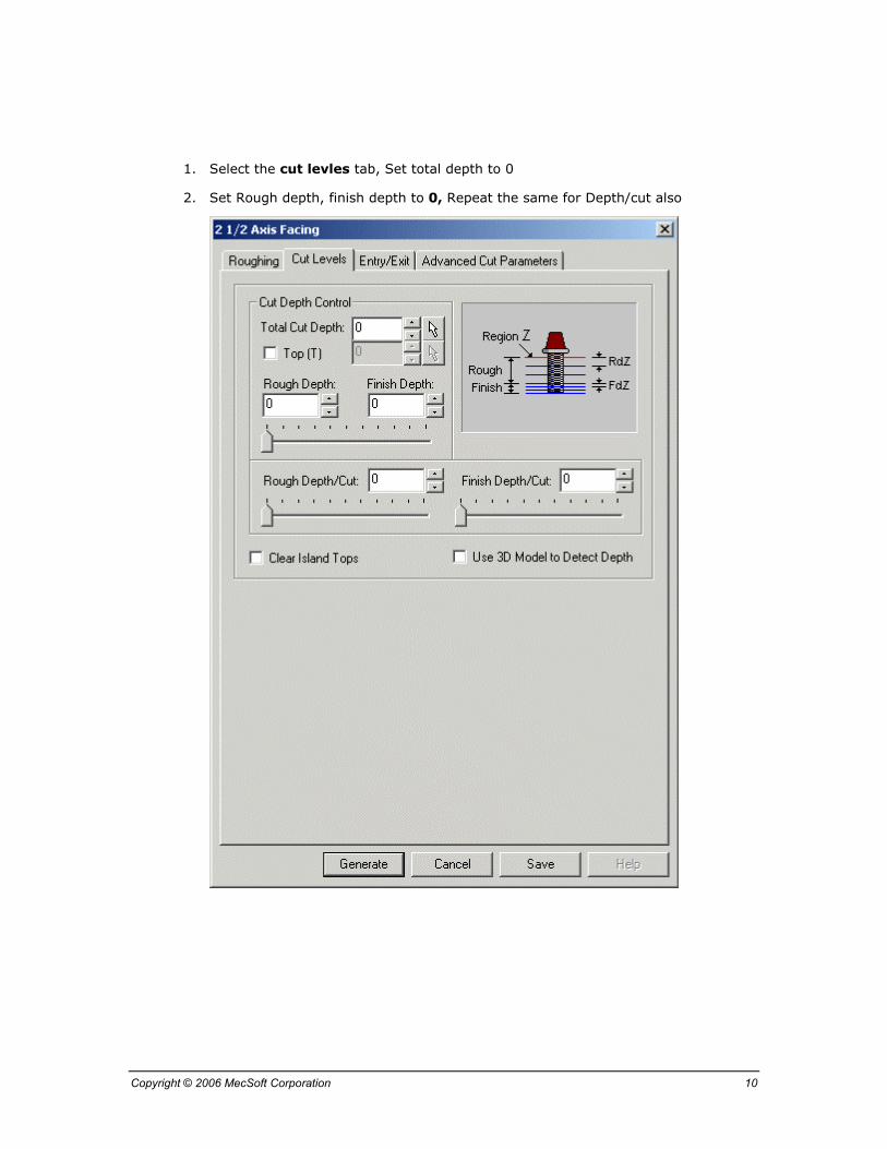
1. Select the cut levles tab, Set total depth to 0
2. Set Rough depth, finish depth to 0, Repeat the same for Depth/cut also

Copyright © 2006 MecSoft Corporation 11
1. Select the Entry/Exits tab, Set values to default values as shown below
2. Press Generate to create tool path

Copyright © 2006 MecSoft Corporation 12
Display Generated Toolpath
If the Hide Toolpath button is unchecked you will see the tool path as shown.

Copyright © 2006 MecSoft Corporation 13
Simulate Facing operation
Select the Stock tab in the browser and press to run the material removal simulation. Once the simulation is completed the cut model will be shown as below.
Create Finishing operations First we will do a parallel finishing operation using 1/8 ball mill and then we will use 1/16-inch ball mill to do final fishing operation. Now in the Tools tab select BallMill1 as the tool for this operation.

Copyright © 2006 MecSoft Corporation 14
Select the regions for parallel finishing 3. Using region selection tools select the inner curve and the four circles for parallel
finishing
4. The curves are shown below, highlighted in the selection color (red in this case as shown)

Copyright © 2006 MecSoft Corporation 15
Create the Machining Operation
1. Select the Mops tab, Click on (3 Axis operation) button and select Parallel finishing
2. Set Intol, outol to 0.001, Stock to 0
3. Set Cut Direction to mixed, Cut start side to Bottom, Angle of cuts to 0
4. Set Step over control to 25%

Copyright © 2006 MecSoft Corporation 16
1. Select the Entry / exit tab as shown
2. Set the approach motion to 0.025, Engage motion all set to zero
3. Set Cut transfer to skim
4. Click on Generate. Please wait it may take few minutes to generate toolpath

Copyright © 2006 MecSoft Corporation 17
Display Generated Toolpath If the Hide Toolpath button is unchecked you will see the tool path as shown.
Simulate parallel finishing operation
Select the Stock tab in the browser and press to run the material removal simulation. Once the simulation is completed the cut model will be shown as below.
Copyright © 2006 MecSoft Corporation 18
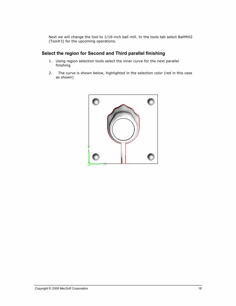
Next we will change the tool to 1/16-inch ball mill. In the tools tab select BallMill2 (Tool#3) for the upcoming operations.
Select the region for Second and Third parallel finishing 1. Using region selection tools select the inner curve for the next parallel
finishing
2. The curve is shown below, highlighted in the selection color (red in this case as shown)

Copyright © 2006 MecSoft Corporation 19
Create the Machining Operation
1. Select the Mops tab, Click on (3 Axis operation) button and select Parallel finishing
2. Set Intol, outol to 0.001, Stock to 0
3. Set Cut Direction to mixed, Cut start side to Bottom, Angle of cuts to 0
4. Set Step over control to 15%

Copyright © 2006 MecSoft Corporation 20
1. Select the Entry / exit tab as shown
2. Set the approach motion to 0.025, Engage motion all set to zero
3. Set Cut transfer to skim
4. Click on Generate. Please wait it may take few minutes to generate toolpath
Display Generated Toolpath

Copyright © 2006 MecSoft Corporation 21
If the Hide Toolpath button is unchecked you will see the tool path as shown.
Simulate parallel finishing operation
Select the Stock tab in the browser and press to run the material removal simulation. Once the simulation is completed the cut model will be shown as below.

Copyright © 2006 MecSoft Corporation 22
Next Parallel finishing operation is similar to the previous one except we will create the tool path at 90 degrees to the previous one. An easy way to do it is to copy and paste the previous parallel finishing operation and Select the parameters tab and change the angle of cuts to 90 as shown below. Press ‘Generate’ to create tool path.
Display Generated Toolpath

Copyright © 2006 MecSoft Corporation 23
If the Hide Toolpath button is unchecked you will see the tool path as shown.
Simulate parallel finishing operation
Select the Stock tab in the browser and press to run the material removal simulation. Once the simulation is completed the cut model will be shown as below.
Next we will use Radial machining to finish the outer holes.

Copyright © 2006 MecSoft Corporation 24
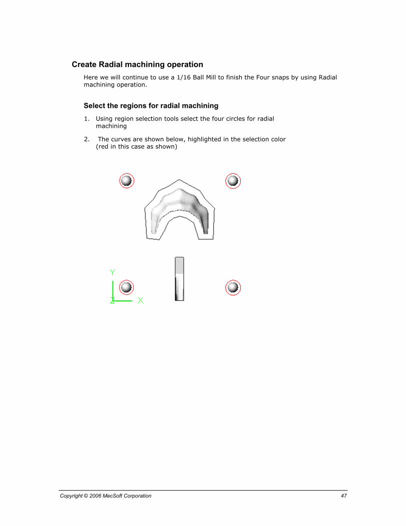
Create Radial Machining operation This operation will provide smooth finish to the four snap holes, which are used to mate with the top half of the mold.
Select the regions for radial machining 1. Using region selection tools select the four circles for the next Radial
Machining
2. The curves are shown below, highlighted in the selection color (red in this case as shown)
Copyright © 2006 MecSoft Corporation 25
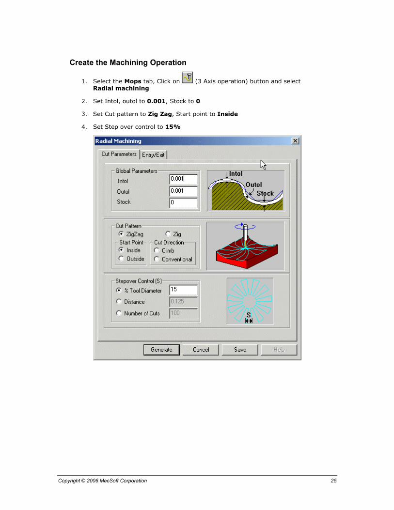
Create the Machining Operation
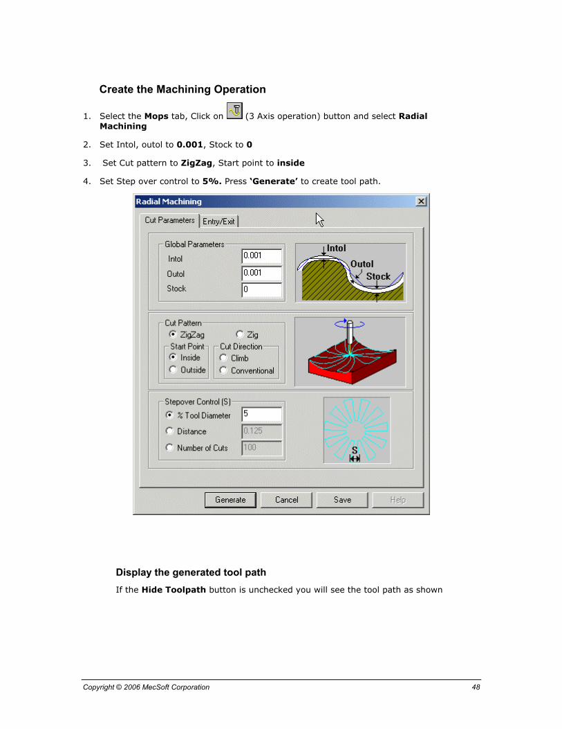
1. Select the Mops tab, Click on (3 Axis operation) button and select Radial machining
2. Set Intol, outol to 0.001, Stock to 0
3. Set Cut pattern to Zig Zag, Start point to Inside
4. Set Step over control to 15%

Copyright © 2006 MecSoft Corporation 26
1. Select the Entry / exit tab as shown
2. Set the approach motion to 0.025, Engage motion to zero
3. Set Cut transfer to skim
4. Click on Generate. Please wait it may take few minutes to generate toolpath
Copyright © 2006 MecSoft Corporation 27
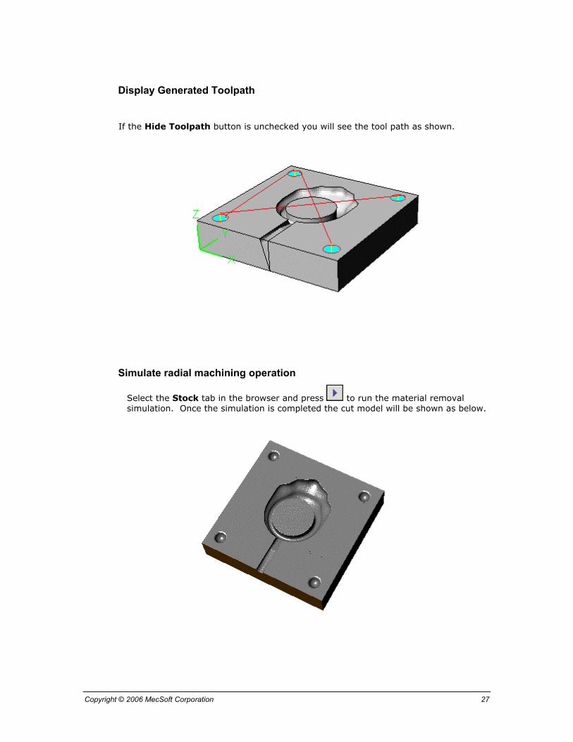
Display Generated Toolpath
If the Hide Toolpath button is unchecked you will see the tool path as shown.
Simulate radial machining operation
Select the Stock tab in the browser and press to run the material removal simulation. Once the simulation is completed the cut model will be shown as below.

Copyright © 2006 MecSoft Corporation 28
Now we have completed the programming all the operations for the Bottom half of the Ring Mold.
Save the file as Ring Mold_BottomComplete.3dm or Ring Mold_BottomComplete.vmp
Next you will create the G code file for machining this part

Copyright © 2006 MecSoft Corporation 29
3. Post-Processing the Programs
Once the toolpaths have been generated, they can be post-processed to a specific machine controller. MecSoft’s products come with a set of post-processors to choose from.
You can post-process a single operation, or all operations at once. For post processing an individual operation, right-click on its name in the Mops tab of the Browser and select Post. You can also select multiple operations and right mouse click and select Post All to post all of the selected operations. To post-process both of the created operations:
1. Select the Mops tab in the browser and select both of the operations created.
2. Right click the mouse button and select Post All
3. This will bring up the dialog shown below with a list of post-processors. Choose the TechoIsel post processor
4. Enter Ring Mold Bottom.nc as the output file for G code file. (Chose the correct path where you wish to write to this file). In the dialog shown below we have chosen to write to the A: or the floppy disk drive.
5. Select the OK button and this will created the G-code file.
Copyright © 2006 MecSoft Corporation 30
4. Creating the Programs for Top half of the mold
Since there is significant differences in top half of the mold as compared to the bottom half of the mold we will use slightly different strategy for machining. We will use the previously created tools. Many of the steps will be similar and in the following section we will discus some of the changes that are necessary to create toolpath for the Top half of the Ring Mold.
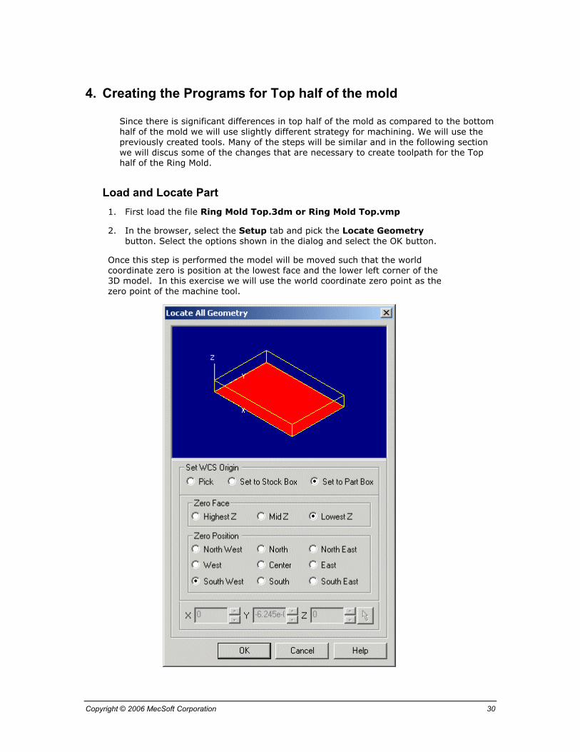
Load and Locate Part 1. First load the file Ring Mold Top.3dm or Ring Mold Top.vmp
2. In the browser, select the Setup tab and pick the Locate Geometry button. Select the options shown in the dialog and select the OK button.
Once this step is performed the model will be moved such that the world coordinate zero is position at the lowest face and the lower left corner of the 3D model. In this exercise we will use the world coordinate zero point as the zero point of the machine tool.

Copyright © 2006 MecSoft Corporation 31
Create Stock Model
1. On the Setup tab in the browser click (create/ load stock) button in the toolbar and select Box Stock option
2. Select the settings shown and also enter the numbers shown in the dialog and select the OK button.
3. Click on the Stock tab on the browser to see the stock you just created.
Once this step is performed the stock model is created and positioned such that the world coordinate zero is at the top left corner of the stock model and also aligned with the lowest Z face of the stock model.
Note: Remember this setting will be used again while setting up the machine zero
This dialog box may appear different in the earlier versions of VisualMill.
Copyright © 2006 MecSoft Corporation 32
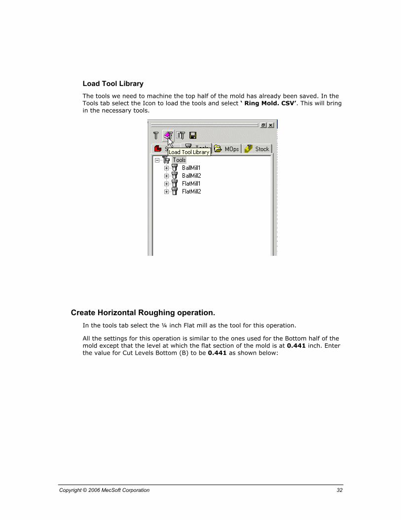
Load Tool Library The tools we need to machine the top half of the mold has already been saved. In the Tools tab select the Icon to load the tools and select ‘ Ring Mold. CSV’. This will bring in the necessary tools.
Create Horizontal Roughing operation. In the tools tab select the ¼ inch Flat mill as the tool for this operation.
All the settings for this operation is similar to the ones used for the Bottom half of the mold except that the level at which the flat section of the mold is at 0.441 inch. Enter the value for Cut Levels Bottom (B) to be 0.441 as shown below:

Copyright © 2006 MecSoft Corporation 33
Press ‘ Generate’ to create the tool path.

Copyright © 2006 MecSoft Corporation 34
Display the generated tool path If the Hide Toolpath button is unchecked you will see the tool path as shown
Simulate Horizontal Roughing operation
Select the Stock tab in the browser and press to run the material removal simulation. Once the simulation is completed the cut model will be shown as below

Copyright © 2006 MecSoft Corporation 35
Create Facing operation In this operation we will use 1/8 inch Flat mill and finish the top flat surface of the mold. We can use the previous Horizontal roughing operation and rerun the tool path with this smaller tool.
Right mouse click on the Horizontal roughing operation and copy and paste this operation. Open the Tools tab (double click Flatmill1) as shown below and In the Tools tab select Tool#2 which is 1/8 inch Flat.
Again Right Click the operations to rename the operation as ‘Facing’. Regenerate the tool path by Pressing ‘Generate’.
Display the generated tool path If the Hide Toolpath button is unchecked you will see the tool path as shown
Simulate Facing operation
Select the Stock tab in the browser and press to run the material removal simulation. Once the simulation is completed the cut model will be shown as below

Copyright © 2006 MecSoft Corporation 36
Create Slot Roughing operation Here we will use a 1/8 Ball Mill to rough out the Slot for the mold by using Horizontal Re-Roughing operation. Once the operation is complete rename the operation as ‘Slot Roughing’.

Copyright © 2006 MecSoft Corporation 37
Select the regions for Slot Roughing
1. Using region selection tools select the rectangle for the slot roughing
2. The curve is shown below, highlighted in the selection color (red in this case as shown)
Copyright © 2006 MecSoft Corporation 38
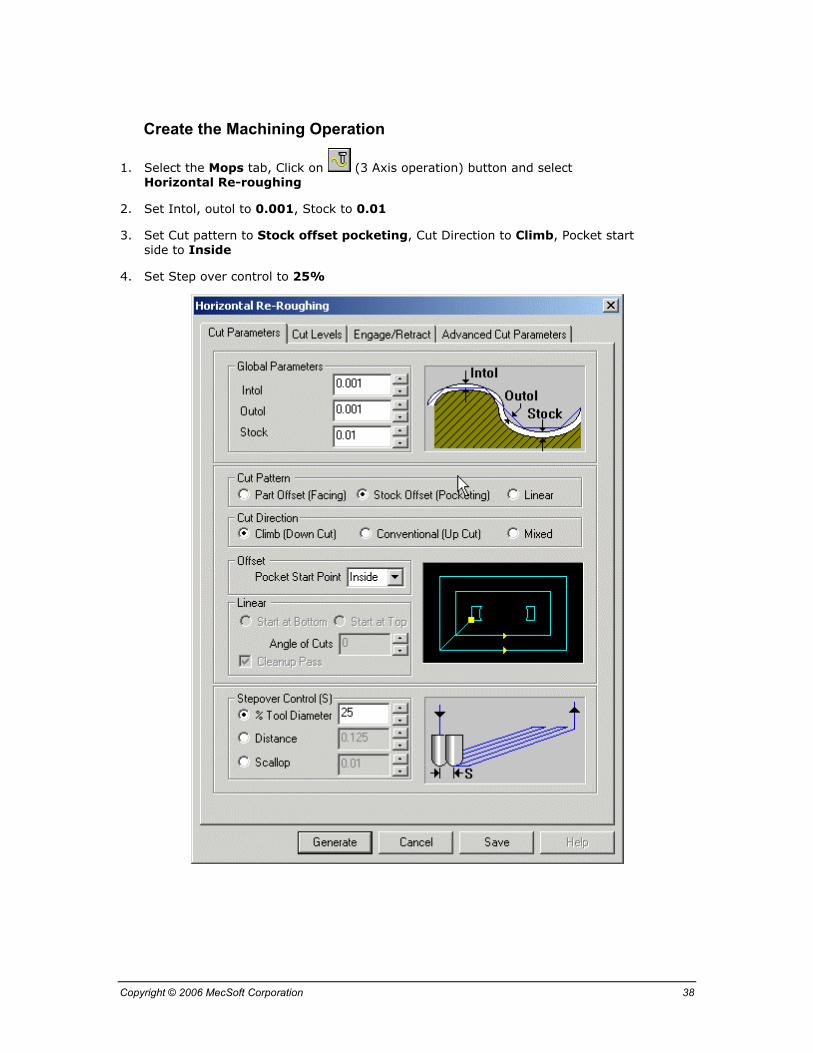
Create the Machining Operation
1. Select the Mops tab, Click on (3 Axis operation) button and select Horizontal Re-roughing
2. Set Intol, outol to 0.001, Stock to 0.01
3. Set Cut pattern to Stock offset pocketing, Cut Direction to Climb, Pocket start side to Inside
4. Set Step over control to 25%

Copyright © 2006 MecSoft Corporation 39
1. Select the Engage/Retract tab as shown
2. Select Ramp, Set Angle to 5, Height to 0.01. Check Always engage in previously cut area if possible
3. Set Linear Extension (D) to 0.275, Set Cut transfer to Skim.
4. Click on Generate, Please wait it may take few minutes to generate toolpath
Copyright © 2006 MecSoft Corporation 40
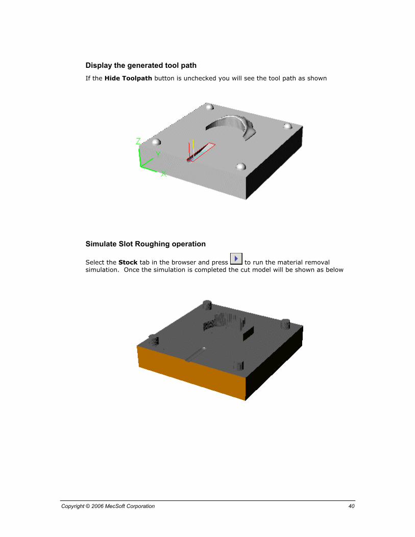
Display the generated tool path If the Hide Toolpath button is unchecked you will see the tool path as shown
Simulate Slot Roughing operation
Select the Stock tab in the browser and press to run the material removal simulation. Once the simulation is completed the cut model will be shown as below

Copyright © 2006 MecSoft Corporation 41
Create Slot Finishing operation Here we will use a 1/16 Ball Mill to finish the Slot for the mold by using Parallel finishing operation. Once the operation is complete rename the operation as ‘Slot finishing’.
Select the region for Slot Finishing
1. Using region selection tools, select the same rectangle for the slot finishing
2. The curve is shown below, highlighted in the selection color (red in this case as shown)
Copyright © 2006 MecSoft Corporation 42
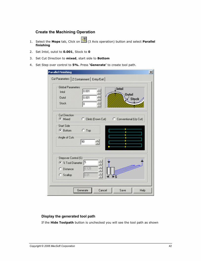
Create the Machining Operation
1. Select the Mops tab, Click on (3 Axis operation) button and select Parallel finishing
2. Set Intol, outol to 0.001, Stock to 0
3. Set Cut Direction to mixed, start side to Bottom
4. Set Step over control to 5%. Press ‘Generate’ to create tool path.
Display the generated tool path If the Hide Toolpath button is unchecked you will see the tool path as shown
Copyright © 2006 MecSoft Corporation 43
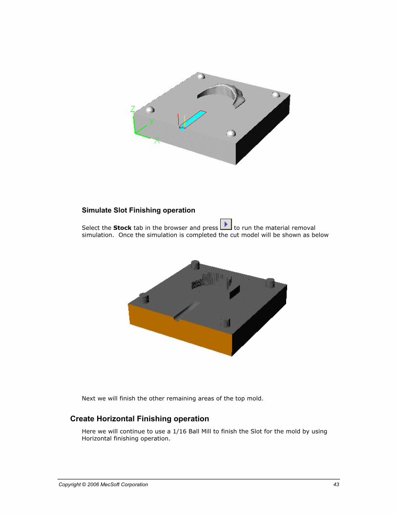
Simulate Slot Finishing operation
Select the Stock tab in the browser and press to run the material removal simulation. Once the simulation is completed the cut model will be shown as below
Next we will finish the other remaining areas of the top mold.
Create Horizontal Finishing operation Here we will continue to use a 1/16 Ball Mill to finish the Slot for the mold by using Horizontal finishing operation.

Copyright © 2006 MecSoft Corporation 44
Select the region for Horizontal Finishing
1. Using region selection tools select the inner curve for the next horizontal finishing
2. The curve is shown below, highlighted in the selection color (red in this case as shown)

Copyright © 2006 MecSoft Corporation 45
Create the Machining Operation
1. Select the Mops tab, Click on (3 Axis operation) button and select Horizontal finishing
2. Set Intol, outol to 0.001, Stock to 0
3. Set Cut Direction to Climb / Conventional
4. In the Cut Levels tab, set the step over to 5%.
5. Press ‘Generate’ to create tool path.
Display the generated tool path If the Hide Toolpath button is unchecked you will see the tool path as shown

Copyright © 2006 MecSoft Corporation 46
Simulate Horizontal Finishing operation
Select the Stock tab in the browser and press to run the material removal simulation. Once the simulation is completed the cut model will be shown as below
Copyright © 2006 MecSoft Corporation 47
Create Radial machining operation Here we will continue to use a 1/16 Ball Mill to finish the Four snaps by using Radial machining operation.
Select the regions for radial machining
1. Using region selection tools select the four circles for radial machining
2. The curves are shown below, highlighted in the selection color (red in this case as shown)
Copyright © 2006 MecSoft Corporation 48
Create the Machining Operation
1. Select the Mops tab, Click on (3 Axis operation) button and select Radial Machining
2. Set Intol, outol to 0.001, Stock to 0
3. Set Cut pattern to ZigZag, Start point to inside
4. Set Step over control to 5%. Press ‘Generate’ to create tool path.
Display the generated tool path If the Hide Toolpath button is unchecked you will see the tool path as shown

Copyright © 2006 MecSoft Corporation 49
Simulate Radial machining operation
Select the Stock tab in the browser and press to run the material removal simulation. Once the simulation is completed the cut model will be shown as below
Now we have completed the programming all the operations for the top half of the Ring Mold.

Copyright © 2006 MecSoft Corporation 50
Save the file as Ring Mold_Top Complete.3dm or Ring Mold_Top Complete.vmp
Next you will create the G code file for machining this part

Copyright © 2006 MecSoft Corporation 51
5. Post-Processing the Programs
Once the toolpaths have been generated, they can be post-processed to a specific machine controller. MecSoft’s products come with a set of post-processors to choose from.
You can post-process a single operation, or all operations at once. For post processing an individual operation, right-click on its name in the Mops tab of the Browser and select Post. You can also select multiple operations and right mouse click and select Post All to post all of the selected operations. To post-process both of the created operations:
1. Select the Mops tab in the browser and select both of the operations created.
2. Right click the mouse button and select Post All
3. This will bring up the dialog shown below with a list of post-processors. Choose the TechoIsel post processor
4. Enter Ring Mold Top.nc as the output file for G code file. (Chose the correct path where you wish to write to this file). In the dialog shown below we have chosen to write to the A: or the floppy disk drive.
5. Select the OK button and this will created the G-code file.
Copyright © 2006 MecSoft Corporation 52
6. Machining the Ring Mold on Techno machine
You will use the files Ring Mold Bottom.NC and Ring Mold Top.NC, the G code files created for The Techno milling machine to machine the bottom and top half of the mold.
Make sure you read the safety instructions recommended by Techno-Isel and follow them strictly It is important to pay attention to these areas before you start machining.
Follow these steps to machine the part:
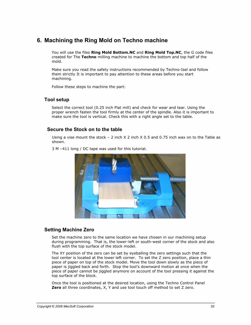
Tool setup Select the correct tool (0.25 inch Flat mill) and check for wear and tear. Using the proper wrench fasten the tool firmly at the center of the spindle. Also it is important to make sure the tool is vertical. Check this with a right angle set to the table.
Secure the Stock on to the table Using a vise mount the stock – 2 inch X 2 inch X 0.5 and 0.75 inch wax on to the Table as shown.
3 M –411 long / DC tape was used for this tutorial.
Setting Machine Zero Set the machine zero to the same location we have chosen in our machining setup during programming. That is, the lower-left or south-west corner of the stock and also flush with the top surface of the stock model.
The XY position of the zero can be set by eyeballing the zero settings such that the tool center is located at the lower left corner. To set the Z zero position, place a thin piece of paper on top of the stock model. Move the tool down slowly as the piece of paper is jiggled back and forth. Stop the tool’s downward motion at once when the piece of paper cannot be jiggled anymore on account of the tool pressing it against the top surface of the block.
Once the tool is positioned at the desired location, using the Techno Control Panel Zero all three coordinates, X, Y and use tool touch off method to set Z zero.

Copyright © 2006 MecSoft Corporation 53
Tool touch off set up is shown below.
Checking Machine Zero Move the Tool up in the Z direction as well as the X and Y different to a different location.
Using control panel, command the machine to travel to the zero position. The Tool should move back to X and Y position that was selected above.
If it does not repeat the previous operation until you are sure that the zero point is located correctly.

Copyright © 2006 MecSoft Corporation 54
Load the file, Pre-process and Preview 1. Using the control panel select File and load the posted file.
2. Once the file is loaded, select Preprocess and then Preview the toolpath
3. It is important to make sure that tool does not go below the top of the table. This can be verified by checking the side view of the toolpath to make sure that there are no tool motions below the bottom most cut level.
4. Set the Spindle to AUTO
Now you are ready to machine the part. Press start and the machine will pause for loading the tool. Press Resume to Continue. The Spindle will turn on and tool will plunge into the stock and profiling and engraving operations will be performed.
Completed Part The completed parts should look like the part shown below: