RigMesh: Automatic Rigging for Part-Based Shape … Automatic Rigging for Part-Based Shape Modeling...
9
RigMesh: Automatic Rigging for Part-Based Shape Modeling and Deformation P´ eter Boros´ an 1* Ming Jin 1 † Doug DeCarlo 1 Yotam Gingold 1,2 Andrew Nealen 1 1 Rutgers University 2 Columbia University Pose Merge Create & Copy Refine & Pose Pose Cut & Merge Pose Refine & Pose Create & Copy & Merge Cut & Merge Pose Merge & Pose Merge Rollback Figure 1: An example RigMesh modeling sequence: the artist experiments with different ideas for a shape by modeling (blue arrows) and posing (green arrows) using our skeletal rig. In the traditional pipeline, modeling and rigging are separate procedures, so the model must be re-rigged every time the shape changes (i.e. after each modeling operation). RigMesh unifies modeling and rigging; the model is always rigged, and the artist can pose freely, allowing for iterative modeling, deformation, and key-frame animation with real-time response. Abstract The creation of a 3D model is only the first stage of the 3D character animation pipeline. Once a model has been created, and before it can be animated, it must be rigged. Manual rigging is labori- ous, and automatic rigging approaches are far from real-time and do not allow for incremental updates. This is a hindrance in the real world, where the shape of a model is often revised after rigging has been performed. In this paper, we introduce algorithms and a user- interface for sketch-based 3D modeling that unify the modeling and rigging stages of the 3D character animation pipeline. Our algorithms create a rig for each sketched part in real-time, and up- date the rig as parts are merged or cut. As a result, users can freely pose and animate their shapes and characters while rapidly iterating on the base shape. The rigs are compatible with the state-of-the- art character animation pipeline; they consist of a low-dimensional skeleton along with skin weights identifying the surface with bones of the skeleton. Keywords: rigging, skeletonization, skinning, animation, sketch- based modeling Links: DL PDF * e-mail: [email protected] † e-mail: [email protected] P´ eter Boros´ an and Ming Jin contributed equally to this work and are placed in alphabetical order. 1 Introduction The task of creating ready-to-animate 3D models is funda- mentally hard; designers and artists spend years becoming proficient at commercial, state-of-the-art tools such as Maya and 3ds Max [Autodesk 2012c; Autodesk 2012a]. In an effort to make freeform 3D modeling more accessible to novices and to enable rapid iterative prototyping, sketch-based tools such as Teddy [Igarashi et al. 1999] and a large body of follow-up work [Tai et al. 2004; Cherlin et al. 2005; Schmidt et al. 2005; Alexe et al. 2005; Karpenko and Hughes 2006; Nealen et al. 2007; Bernhardt et al. 2008; Sugihara et al. 2008; Pihuit et al. 2010; Cordier et al. 2011] introduced techniques to create plausible 3D models from 2D freeform strokes. (See [Olsen et al. 2009] for a recent survey.) While these tools greatly simplify shape modeling, modeling is only the first stage of the 3D animation pipeline. Once a model has been created, and before it can be animated, it must be rigged. In the state-of-the-art character animation pipeline, a rig takes the form of a skeleton, a cycle-free graph whose nodes are called joints and whose edges are called bones, and skin weights identifying the surface of the model with the bones of the skeleton [Magnenat-Thalmann et al. 1988; Lewis et al. 2000]. Rigging can be performed manually, by designing the skeleton and then laboriously painting the surface with skin weights for each bone. Various computational methods exist for auto- matic skeleton extraction [Sharf et al. 2007; Cornea et al. 2007; Au et al. 2008; Pan et al. 2009] and skinning [Lewis et al. 2000; Bloomenthal 2002; Kry et al. 2002; Mohr and Gleicher 2003; Weber et al. 2007; Baran and Popovi´ c 2007; Wang et al. 2007; Yang and W¨ unsche 2010; Miller et al. 2010]. In this paper, we take advantage of these recent advances in the literature, and further simplify the process of creating ready-to- animate 3D models by combining shape creation, modification and posing into a single coherent framework. However, this cannot be achieved trivially by integrating existing tools. Sketch-based modeling tools like Teddy [1999] and FiberMesh [2007] do not explicitly maintain a skeleton. Automatically adding the skeleton (e.g. [Au et al. 2008]) and rigging (e.g. [Baran and Popovi´ c 2007]) as a post-process typically does not allow for real-time interac- tions. Furthermore, in our discussions with professional anima-
Transcript of RigMesh: Automatic Rigging for Part-Based Shape … Automatic Rigging for Part-Based Shape Modeling...
RigMesh: Automatic Rigging for Part-Based Shape Modeling and Deformation
Peter Borosan1∗ Ming Jin1† Doug DeCarlo1 Yotam Gingold1,2 Andrew Nealen1
1Rutgers University 2Columbia University
PoseMergeCreate & Copy
Refine & Pose PoseCut & Merge PoseRefine & PoseCreate & Copy & Merge Cut & Merge
PoseMerge & PoseMerge Rollback
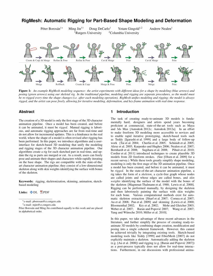
Figure 1: An example RigMesh modeling sequence: the artist experiments with different ideas for a shape by modeling (blue arrows) andposing (green arrows) using our skeletal rig. In the traditional pipeline, modeling and rigging are separate procedures, so the model mustbe re-rigged every time the shape changes (i.e. after each modeling operation). RigMesh unifies modeling and rigging; the model is alwaysrigged, and the artist can pose freely, allowing for iterative modeling, deformation, and key-frame animation with real-time response.
Abstract
The creation of a 3D model is only the first stage of the 3D characteranimation pipeline. Once a model has been created, and beforeit can be animated, it must be rigged. Manual rigging is labori-ous, and automatic rigging approaches are far from real-time anddo not allow for incremental updates. This is a hindrance in the realworld, where the shape of a model is often revised after rigging hasbeen performed. In this paper, we introduce algorithms and a user-interface for sketch-based 3D modeling that unify the modelingand rigging stages of the 3D character animation pipeline. Ouralgorithms create a rig for each sketched part in real-time, and up-date the rig as parts are merged or cut. As a result, users can freelypose and animate their shapes and characters while rapidly iteratingon the base shape. The rigs are compatible with the state-of-the-art character animation pipeline; they consist of a low-dimensionalskeleton along with skin weights identifying the surface with bonesof the skeleton.
Keywords: rigging, skeletonization, skinning, animation, sketch-based modeling
Links: DL PDF
∗e-mail: [email protected]†e-mail: [email protected]
Peter Borosan and Ming Jin contributed equally to this work and are placedin alphabetical order.
1 Introduction
The task of creating ready-to-animate 3D models is funda-mentally hard; designers and artists spend years becomingproficient at commercial, state-of-the-art tools such as Mayaand 3ds Max [Autodesk 2012c; Autodesk 2012a]. In an effortto make freeform 3D modeling more accessible to novices andto enable rapid iterative prototyping, sketch-based tools suchas Teddy [Igarashi et al. 1999] and a large body of follow-upwork [Tai et al. 2004; Cherlin et al. 2005; Schmidt et al. 2005;Alexe et al. 2005; Karpenko and Hughes 2006; Nealen et al. 2007;Bernhardt et al. 2008; Sugihara et al. 2008; Pihuit et al. 2010;Cordier et al. 2011] introduced techniques to create plausible 3Dmodels from 2D freeform strokes. (See [Olsen et al. 2009] for arecent survey.) While these tools greatly simplify shape modeling,modeling is only the first stage of the 3D animation pipeline. Oncea model has been created, and before it can be animated, it mustbe rigged. In the state-of-the-art character animation pipeline, arig takes the form of a skeleton, a cycle-free graph whose nodesare called joints and whose edges are called bones, and skinweights identifying the surface of the model with the bones ofthe skeleton [Magnenat-Thalmann et al. 1988; Lewis et al. 2000].Rigging can be performed manually, by designing the skeletonand then laboriously painting the surface with skin weightsfor each bone. Various computational methods exist for auto-matic skeleton extraction [Sharf et al. 2007; Cornea et al. 2007;Au et al. 2008; Pan et al. 2009] and skinning [Lewis et al. 2000;Bloomenthal 2002; Kry et al. 2002; Mohr and Gleicher 2003;Weber et al. 2007; Baran and Popovic 2007; Wang et al. 2007;Yang and Wunsche 2010; Miller et al. 2010].
In this paper, we take advantage of these recent advances in theliterature, and further simplify the process of creating ready-to-animate 3D models by combining shape creation, modification andposing into a single coherent framework. However, this cannotbe achieved trivially by integrating existing tools. Sketch-basedmodeling tools like Teddy [1999] and FiberMesh [2007] do notexplicitly maintain a skeleton. Automatically adding the skeleton(e.g. [Au et al. 2008]) and rigging (e.g. [Baran and Popovic 2007])as a post-process typically does not allow for real-time interac-tions. Furthermore, in our discussions with professional anima-
tors [Shukan 2012], we have learned that they often need to revisethe geometry of their models after they have been rigged (Fig. 1illustrates this process). Such incremental updates to the shapesare especially difficult with the aforementioned tools. We believethe fundamental problem lies in the conventional pipeline wheremodeling and rigging are treated as two entirely separate processes.Shapes are modeled before they can be rigged; if the base shaperequires any modifications at a later time, the skeleton has to bere-computed, and the rig re-designed.
Thus, in contrast with the traditional, sequential view of modelingand rigging, we propose to unify these steps and introducealgorithms for sketch-based modeling by parts that maintaina rigged mesh at all times. Our algorithms generate arigged mesh—a surface, a skeleton, and skin weights—foreach sketched part and update it as parts are merged or cut.Modeling by parts is consistent with human recognition of shapesby components [Biederman 1987], and has been employed bymodeling approaches such as ShapeShop [Schmidt et al. 2005]for CSG operations on individual sketched parts; Gingold etal. [2009] for single-view modeling from existing sketches;and the SPORE Creature Creator [Maxis 2008], as wellas SnapPaste [Sharf et al. 2006], Shuffler [Kraevoy et al. 2007],meshmixer [Schmidt and Singh 2010], the works of Chaudhuri etal. [2011], and Funkhouser et al. [2004] for re-using parts of exist-ing models.
By unifying modeling and rigging, artists can freely pose theshape while modeling to adjust it, or to examine the motionof the model by using poses as key-frames. Furthermore,the unification removes friction from incremental and iterativecharacter modeling and animation (Fig. 1). Our algorithms areefficient and execute in real-time, far below the one second delaythat interrupts mental flow [Nielsen 1993]. Our work buildson Pinocchio [Baran and Popovic 2007], adapting its skin weightalgorithm to support incremental merging and cutting of shapes,and revisits the Chordal Axis Transform [Prasad 1997] used byTeddy [Igarashi et al. 1999] for skeleton generation. Specifically,our contributions are:
• A unified approach to modeling and rigging, eliminating a re-curring step from the professional 3D animation pipeline.
• A modification of the Douglas-Peucker algorithm [1973] forcreating a high-quality skeleton from the sketched outline ofa shape.
• An efficient method for locally re-computing skin weights tomaintain a valid, high-quality rig when merging or cuttingshapes.
Note that a variety of hierarchical approaches to smoothsurface modeling exist in the literature, such as theseminal BlobTrees [Wyvill et al. 1999] and aforementionedShapeShop [Schmidt et al. 2005], as well as other approaches
based on convolution surfaces [Sherstyuk 1999; Alexe et al. 2005;Allegre et al. 2006]. While a convenient representation formodeling and animation, CSG-based hierarchies are quite differentfrom the rigged models preferred in professional character anima-tion pipelines, which are based on surfaces, skeletons, and skinweights. Also notably, a system that shares some similarity withour work flow is the ZSpheres tool of ZBrush [Pixologic 2012], inwhich a base model is created by connecting spheres of varyingradii with tapered cylinders. While ZSpheres allows for base modelcreation and posing at the same time, this base model only servesas a bone skeleton and rig, from which the surface mesh needs tobe sculpted as a separate step. Furthermore, our system differsfrom ZSpheres in being sketch-based and by supporting modelingby parts, which enables part re-use.
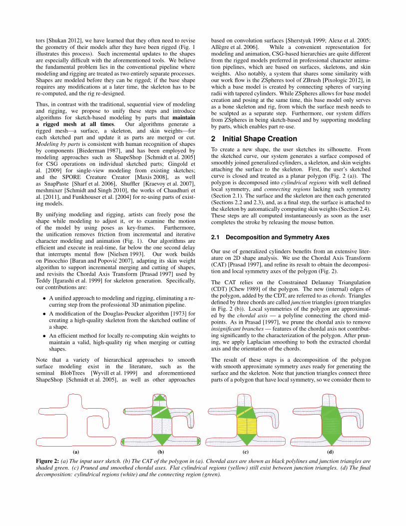
2 Initial Shape CreationTo create a new shape, the user sketches its silhouette. Fromthe sketched curve, our system generates a surface composed ofsmoothly joined generalized cylinders, a skeleton, and skin weightsattaching the surface to the skeleton. First, the user’s sketchedcurve is closed and treated as a planar polygon (Fig. 2 (a)). Thepolygon is decomposed into cylindrical regions with well definedlocal symmetry, and connecting regions lacking such symmetry(Section 2.1). The surface and the skeleton are then each generated(Sections 2.2 and 2.3), and, as a final step, the surface is attached tothe skeleton by automatically computing skin weights (Section 2.4).These steps are all computed instantaneously as soon as the usercompletes the stroke by releasing the mouse button.
2.1 Decomposition and Symmetry Axes
Our use of generalized cylinders benefits from an extensive liter-ature on 2D shape analysis. We use the Chordal Axis Transform(CAT) [Prasad 1997], and refine its result to obtain the decomposi-tion and local symmetry axes of the polygon (Fig. 2).
The CAT relies on the Constrained Delaunay Triangulation(CDT) [Chew 1989] of the polygon. The new (internal) edges ofthe polygon, added by the CDT, are referred to as chords. Trianglesdefined by three chords are called junction triangles (green trianglesin Fig. 2 (b)). Local symmetries of the polygon are approximat-ed by the chordal axis — a polyline connecting the chord mid-points. As in Prasad [1997], we prune the chordal axis to removeinsignificant branches — features of the chordal axis not contribut-ing significantly to the characterization of the polygon. After prun-ing, we apply Laplacian smoothing to both the extracted chordalaxis and the orientation of the chords.
The result of these steps is a decomposition of the polygonwith smooth approximate symmetry axes ready for generating thesurface and the skeleton. Note that junction triangles connect threeparts of a polygon that have local symmetry, so we consider them to
(a) (b) (c) (d)
Figure 2: (a) The input user sketch. (b) The CAT of the polygon in (a). Chordal axes are shown as black polylines and junction triangles areshaded green. (c) Pruned and smoothed chordal axes. Flat cylindrical regions (yellow) still exist between junction triangles. (d) The finaldecomposition: cylindrical regions (white) and the connecting region (green).
(a) (b) (c) (d) (e) (f)
Figure 3: Generating the 3D surface mesh. (a) Generalized cylinders (yellow) are created from cylindrical regions. (b) and (c) are side-viewsshown with coarser tessellation for illustration purposes. (Orientation is indicated by the red/green coordinate axes.) (b) The semi-circlesof neighboring generalized cylinders are connected by lines. (c) Uniformly sampled points along these lines are stitched together to formtriangle strips. (d) Frontal view after steps in (b) and (c). (e) Using the boundary vertices, GridMesh [Nealen et al. 2009] covers the holes(green) and provides a water-tight mesh. (f) The surface is smoothed using Least-Squares Meshes [Sorkine and Cohen-Or 2004].
be connecting regions. The remainder of the polygon can be treatedas cylindrical regions. There may also be short-yet-wide cylindri-cal regions between junction triangles (yellow in Fig. 2 (c)), whichwould lead to the creation of flat, disc-like surfaces. Such regionsare merged with the neighboring junction triangles to form largerconnecting regions (green in Fig. 2 (d)), alongside the elongatedcylindrical regions (remainder of polygon in Fig. 2 (d)).
The use of these techniques is inspired by Teddy. However, Teddyonly uses the CAT for surface inflation from a 2D silhouette anddiscards it afterwards; we, however, further process the chordal axisto generate the skeleton (Section 2.3).
2.2 Surface generation
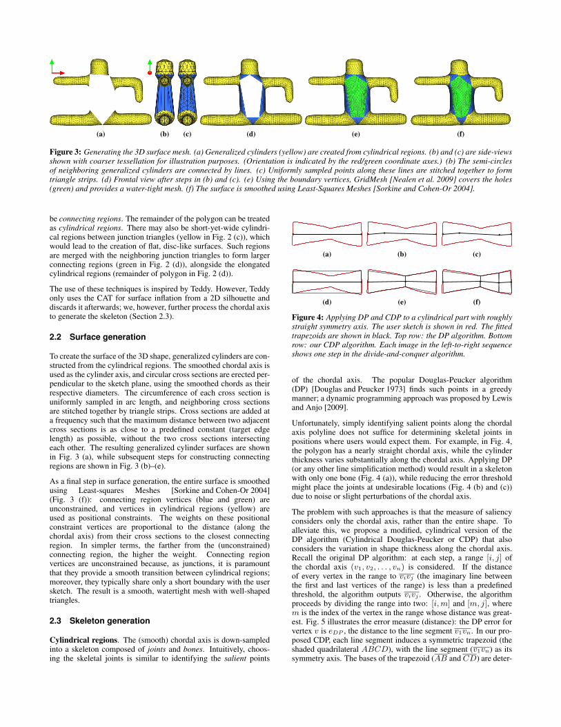
To create the surface of the 3D shape, generalized cylinders are con-structed from the cylindrical regions. The smoothed chordal axis isused as the cylinder axis, and circular cross sections are erected per-pendicular to the sketch plane, using the smoothed chords as theirrespective diameters. The circumference of each cross section isuniformly sampled in arc length, and neighboring cross sectionsare stitched together by triangle strips. Cross sections are added ata frequency such that the maximum distance between two adjacentcross sections is as close to a predefined constant (target edgelength) as possible, without the two cross sections intersectingeach other. The resulting generalized cylinder surfaces are shownin Fig. 3 (a), while subsequent steps for constructing connectingregions are shown in Fig. 3 (b)–(e).
As a final step in surface generation, the entire surface is smoothedusing Least-squares Meshes [Sorkine and Cohen-Or 2004](Fig. 3 (f)): connecting region vertices (blue and green) areunconstrained, and vertices in cylindrical regions (yellow) areused as positional constraints. The weights on these positionalconstraint vertices are proportional to the distance (along thechordal axis) from their cross sections to the closest connectingregion. In simpler terms, the farther from the (unconstrained)connecting region, the higher the weight. Connecting regionvertices are unconstrained because, as junctions, it is paramountthat they provide a smooth transition between cylindrical regions;moreover, they typically share only a short boundary with the usersketch. The result is a smooth, watertight mesh with well-shapedtriangles.
2.3 Skeleton generation
Cylindrical regions. The (smooth) chordal axis is down-sampledinto a skeleton composed of joints and bones. Intuitively, choos-ing the skeletal joints is similar to identifying the salient points
(a) (b) (c)
(d) (e) (f)
Figure 4: Applying DP and CDP to a cylindrical part with roughlystraight symmetry axis. The user sketch is shown in red. The fittedtrapezoids are shown in black. Top row: the DP algorithm. Bottomrow: our CDP algorithm. Each image in the left-to-right sequenceshows one step in the divide-and-conquer algorithm.
of the chordal axis. The popular Douglas-Peucker algorithm(DP) [Douglas and Peucker 1973] finds such points in a greedymanner; a dynamic programming approach was proposed by Lewisand Anjo [2009].
Unfortunately, simply identifying salient points along the chordalaxis polyline does not suffice for determining skeletal joints inpositions where users would expect them. For example, in Fig. 4,the polygon has a nearly straight chordal axis, while the cylinderthickness varies substantially along the chordal axis. Applying DP(or any other line simplification method) would result in a skeletonwith only one bone (Fig. 4 (a)), while reducing the error thresholdmight place the joints at undesirable locations (Fig. 4 (b) and (c))due to noise or slight perturbations of the chordal axis.
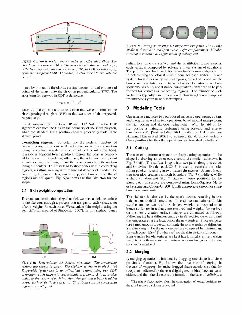
The problem with such approaches is that the measure of saliencyconsiders only the chordal axis, rather than the entire shape. Toalleviate this, we propose a modified, cylindrical version of theDP algorithm (Cylindrical Douglas-Peucker or CDP) that alsoconsiders the variation in shape thickness along the chordal axis.Recall the original DP algorithm: at each step, a range [i, j] ofthe chordal axis (v1, v2, . . . , vn) is considered. If the distanceof every vertex in the range to vivj (the imaginary line betweenthe first and last vertices of the range) is less than a predefinedthreshold, the algorithm outputs vivj . Otherwise, the algorithmproceeds by dividing the range into two: [i,m] and [m, j], wherem is the index of the vertex in the range whose distance was great-est. Fig. 5 illustrates the error measure (distance): the DP error forvertex v is eDP , the distance to the line segment v1vn. In our pro-posed CDP, each line segment induces a symmetric trapezoid (theshaded quadrilateral ABCD), with the line segment (v1vn) as itssymmetry axis. The bases of the trapezoid (AB and CD) are deter-
B C
D
F
A
e1
e2
v1
vnve
DP
v
E
Figure 5: Error terms for vertex v in DP and CDP algorithms. Thechordal axis is shown in blue. The user sketch is shown in red. v1vnis the line segment added in one step of DP; In CDP, besides v1vn,symmetric trapezoid ABCD (shaded) is also added to evaluate theerror term.
mined by projecting the chords passing through v1 and vn, the endpoints of the range, onto the direction perpendicular to v1vn. Theerror term for vertex v in CDP is defined as:
eCDP = e21 + e22
where e1 and e2 are the distances from the two end points of thechord passing through v (EF ) to the two sides of the trapezoid,respectively.
Fig. 4 compares the results of DP and CDP. Note how the CDPalgorithm captures the kink in the boundary of the input polygon,while the standard DP algorithm chooses potentially undesirableskeletal joints.
Connecting regions. To determine the skeletal structure ofconnecting regions, a joint is placed at the center of each junctiontriangle and a bone is added across each of its three sides (Fig. 6(a)).If a side is adjacent to a cylindrical region, the bone is connect-ed to the end of its skeleton; otherwise, the side must be adjacentto another junction triangle, and the bone connects both junctiontriangles’ centers. This may lead to short bones within connectingregions, resulting in a rig with redundant degrees of freedom forcontrolling the shape. Thus, as a last step, short bones inside “thick”regions are collapsed. Fig. 6(b) shows the final skeleton for theshape.
2.4 Skin weight computation
To create (and maintain) a rigged model, we must attach the surfaceto the skeleton through a process that assigns to each vertex a setof skin weights for each bone. We calculate skin weights using theheat diffusion method of Pinocchio [2007]. In this method, bones
(a) (b)
Figure 6: Determining the skeletal structure. The connectingregions are shown in green. The skeleton is shown in black. (a)Trapezoids (gray) are fit to cylindrical regions using our CDPalgorithm; each trapezoid corresponds to a bone. A joint is alsoadded at the center of each junction triangle, and a bone is addedacross each of its three sides. (b) Short bones inside connectingregions are collapsed.
Figure 7: Cutting an existing 3D shape into two parts. The cuttingstroke is shown as a red open curve. Left: cut placement. Middle:result of a smooth cut. Right: result of a sharp cut
radiate heat onto the surface, and the equilibrium temperature ateach vertex is computed by solving a linear system of equations.The performance bottleneck for Pinocchio’s skinning algorithm isin determining the closest visible bone for each vertex. In oursystem, for vertices on cylindrical regions, the set of closest visiblebones and their distances are trivially known at creation time. Con-sequently, visibility and distance computations only need to be per-formed for vertices in connecting regions. The number of suchvertices is typically small; as a result, skin weights are computedinstantaneously for all of our examples.
3 Modeling Tools
Our interface includes two part-based modeling operations, cuttingand merging, as well as two operations based around manipulatingthe rig, posing and skeleton refinement. With the aid of therig, posing is naturally performed using forward and inversekinematics (IK) [Watt and Watt 1991]. (We use dual quaternionskinning [Kavan et al. 2008] to compute the deformed surface.)Our algorithms for the other operations are described as follows.
3.1 Cutting
The user can perform a smooth or sharp cutting operation on theshape by drawing an open curve across the model, as shown inFig. 7 (left). The surface is split into two parts along this curve,and GridMesh [Nealen et al. 2009] is used to generate the hole-filling patches, resulting in two watertight meshes. A smooth cut-ting operation creates a smooth boundary (Fig. 7 (middle)), whilea sharp cut does not (Fig. 7 (right)). Vertex positions for theglued patch of surface are computed using Least-Squares Mesh-es [Sorkine and Cohen-Or 2004], with appropriate smooth or sharpboundary constraints.
The skeleton is also cut by the user’s stroke, resulting in twoindependent skeletal structures. In order to maintain valid skinweights on the two resulting shapes, weights corresponding tobones no longer in a shape are removed and weights for verticeson the newly created surface patches are computed as follows.Following the heat diffusion analogy in Pinocchio, we wish to findthe temperatures at the locations of the new vertices. Since tempera-ture varies smoothly, we can compute the skin weights by diffusion.So, skin weights for the new vertices are computed by minimizing,for each bone, ∥∆wi∥2, where wi are the skin weights for bone i. 1
Skin weights for old vertices are kept fixed. Finally, since the skinweights at both new and old vertices may no longer sum to one,they are normalized.
3.2 Merging
A merging operation is initiated by dragging one shape into closeproximity of another. Fig. 8 shows the three types of merging: Inthe case of snapping, the entire dragged shape translates so that thetwo joints indicated by the user (highlighted in blue) become coin-cident, and then the skeletons are joined. In the case of splitting, a
1The matrix factorization from the computation of vertex positions forthe glued surface patch can be re-used.
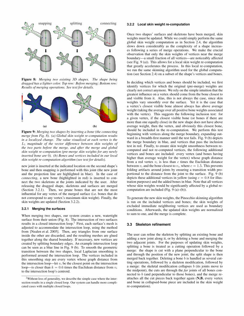
Figure 8: Merging two existing 3D shapes. The shape beingdragged has a lighter color. Top row: Before merging; Bottom row:Results of merging operations. See text for details.
2
0
(a) (b)
Figure 9: Merging two shapes by inserting a bone (the connectingmerge from Fig. 8). (a) Global skin weight re-computation resultsin a localized change. The value visualized at each vertex is theL1 magnitude of the vector difference between skin weights ofthe two parts before the merge, and after the merge and globalskin weight re-computation (pre-merge skin weights for any newlyinserted bone are 0). (b) Bones and vertices included in our localskin weight re-computation algorithm (see text for details).
new joint is inserted at the indicated location on the second shape’sbone and then snapping is performed with this joint (the new jointand the projection line are highlighted in blue). In the case ofconnecting, a new bone (highlighted in red) is inserted to con-nect the two skeletons at the joints indicated by the user. Afterreleasing the dragged shape, skeletons and surfaces are merged(Section 3.2.1). Then, we prune bones that are not the mostinfluential for any vertex of the merged surface (i.e. bones that donot correspond to any vertex’s maximum skin weight). Finally, theskin weights are updated (Section 3.2.2).
3.2.1 Merging the surfaces
When merging two shapes, our system creates a new, watertightsurface from their union (Fig. 8). The intersection of two surfacesresults in a closed intersection loop.2 First, each surface’s mesh isadjusted to accommodate the intersection loop, using the methodfrom [Nealen et al. 2005]. Then, any triangles from one surfaceinside the other are discarded, and the resulting meshes are gluedtogether along the shared boundary. If necessary, new vertices arecreated by splitting boundary edges. An example intersection loopcan be seen as a blue line in Fig. 9 (b). To smooth the geometrictransition between the two shapes, local Laplacian smoothing isperformed around the intersection loop. The vertices included inthis smoothing step are every vertex whose graph distance fromthe intersection loop—let vi be the closest point on the intersectionloop—is closer than k = 0.6 times the Euclidean distance from vito the intersection loop’s centroid.
2Without loss of generality, we describe the simple case where the inter-section results in a single closed loop. Our system can handle more compli-cated cases with multiple closed loops.
3.2.2 Local skin weight re-computation
Once two shapes’ surfaces and skeletons have been merged, skinweights must be updated. While we could simply perform the sameglobal skin weight computation as in Section 2.4, the algorithmslows down considerably as the complexity of a shape increas-es following a series of merge operations. We make the crucialobservation that only the skin weights of vertices near the mergeboundary—a small fraction of all vertices—are noticeably affected(see Fig. 9 (a)). This allows for a local skin weight re-computationthat greatly accelerates the process. In this local re-computation,we run the same skinning algorithm used for the global computa-tion (see Section 2.4) on a subset of the shape’s vertices and bones.
In deciding which vertices and bones should be included, we firstidentify vertices for which the original (pre-merge) weights areclearly not correct anymore. We rely on the simple intuition that thegreatest influence on a vertex should come from the bone closest toand visible from it. Alas, this is not always the case, since skinweights vary smoothly over the surface. Yet it is the case thata vertex’s closest visible bone almost always has above averageweight (taking the average over all positive bone weights associatedwith the vertex). This suggests the following inclusion test: fora given vertex, if the closest visible bone (or bones if there aremore than one equally close) in the new shape does not have aboveaverage weight, then the vertex, and obviously this closest bone,should be included in the re-computation. We perform this testbeginning with vertices along the merge boundary, expanding out-ward in a breadth-first manner until the test fails. Fig. 9 (b) depictsthe merge boundary in blue, and vertices that pass the inclusiontest in red. Finally, to ensure skin weight smoothness between re-computed and not re-computed vertices, the following additionalvertices and bones are included: every vertex (and bones havinghigher than average weight for the vertex) whose graph distancefrom a red vertex vi is less than c times the Euclidean distancebetween vi and the bone closest to vi, where c = 1.5. This preventsfolding artifacts around joints by ensuring a transition width pro-portional to the distance from the joint to the surface. Fig. 9 (b)depicts these additional vertices in yellow (using c = 0.8 for illus-tration purposes) and the added bones in blue. Note that all verticeswhose skin weights would be significantly affected by a global re-computation are included (Fig. 9 (a)–(b)).
To generate the new skin weights, the Pinocchio skinning algorithmis run on the included vertices and bones; the skin weights ofexcluded immediate neighboring vertices are used as boundaryconditions. Afterwards, the updated skin weights are normalizedto sum to one, and the merge is complete.
3.3 Skeleton refinement
The user can refine the skeleton by splitting an existing bone andadding a new joint along it, or by deleting a bone and merging thetwo adjacent joints. For the purposes of updating skin weights,splitting a bone is treated as a cutting operation followed by amerge: the shape is cut with a plane perpendicular to the boneand through the position of the new joint; the split shape is thenmerged back together. Deleting a bone b is handled as several cut-ting operations, followed by a skeleton modification, followed bya merge: the skeletal modification collapses b (its joints move tothe midpoint), the cuts are through the far joints of all bones con-nected to b (and perpendicular to those bones), and the merge re-attaches all the cut pieces back together again (N.B. every vertexand bone in collapsed-bone piece are included in the skin weightre-computation).
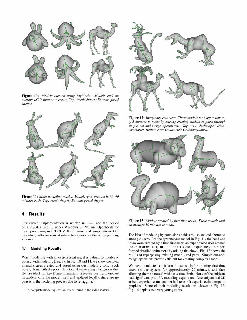
Figure 10: Models created using RigMesh. Models took anaverage of 20 minutes to create. Top: result shapes; Bottom: posedshapes.
Figure 11: More modeling results. Models were created in 30–40minutes each. Top: result shapes; Bottom: posed shapes.
4 Results
Our current implementation is written in C++, and was testedon a 2.8GHz Intel i7 under Windows 7. We use OpenMesh formesh processing and CHOLMOD for numerical computations. Ourmodeling software runs at interactive rates (see the accompanyingvideos).
4.1 Modeling Results
When modeling with an ever-present rig, it is natural to interleaveposing with modeling (Fig. 1). In Fig. 10 and 11, we show complexanimal shapes created and posed using our modeling tool. Suchposes, along with the possibility to make modeling changes on-the-fly, are ideal for key-frame animation. Because our rig is createdin tandem with the model itself and updated locally, there are nopauses in the modeling process due to re-rigging.3
3A complete modeling session can be found in the video materials.
Figure 12: Imaginary creatures. These models took approximate-ly 5 minutes to make by reusing existing models or parts throughsimple cut-and-merge operations. Top row: Jackalope; Dino-camelaroo. Bottom row: Octocamel; Crabadogotaurus.
Figure 13: Models created by first-time users. These models tookan average 30 minutes to make.
The idea of modeling by parts also enables re-use and collaborationamongst users. For the tyrannosaur model in Fig. 11, the head andtorso were created by a first-time user; an experienced user createdthe front-arms, feet, and tail; and a second experienced user per-formed detailed refinement by adding the claws. Fig. 12 shows theresults of repurposing existing models and parts. Simple cut-and-merge operations proved efficient for creating complex shapes.
We have conducted an informal user study by training first-timeusers on our system for approximately 20 minutes, and thenallowing them to model without a time limit. None of the subjectshad significant prior 3D modeling experience. One subject had 2Dartistic experience and another had research experience in computergraphics. Some of their modeling results are shown in Fig. 13.Fig. 14 depicts two very young users.
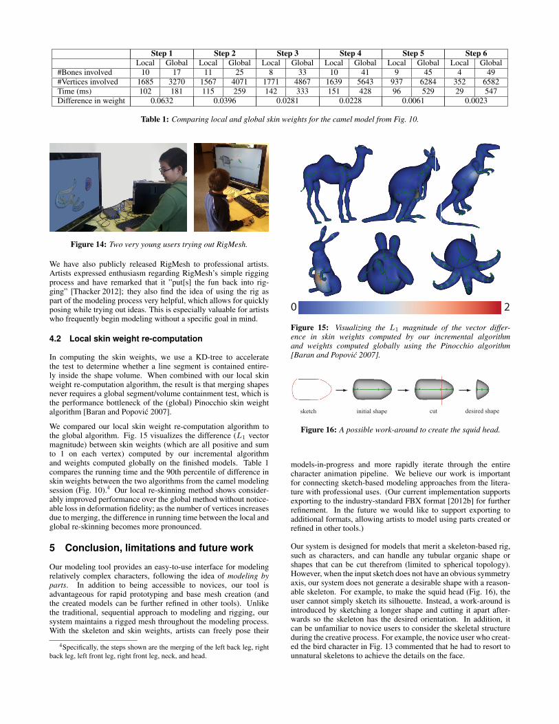
Step 1 Step 2 Step 3 Step 4 Step 5 Step 6Local Global Local Global Local Global Local Global Local Global Local Global
#Bones involved 10 17 11 25 8 33 10 41 9 45 4 49#Vertices involved 1685 3270 1567 4071 1771 4867 1639 5643 937 6284 352 6582Time (ms) 102 181 115 259 142 333 151 428 96 529 29 547Difference in weight 0.0632 0.0396 0.0281 0.0228 0.0061 0.0023
Table 1: Comparing local and global skin weights for the camel model from Fig. 10.
Figure 14: Two very young users trying out RigMesh.
We have also publicly released RigMesh to professional artists.Artists expressed enthusiasm regarding RigMesh’s simple riggingprocess and have remarked that it ”put[s] the fun back into rig-ging” [Thacker 2012]; they also find the idea of using the rig aspart of the modeling process very helpful, which allows for quicklyposing while trying out ideas. This is especially valuable for artistswho frequently begin modeling without a specific goal in mind.
4.2 Local skin weight re-computation
In computing the skin weights, we use a KD-tree to acceleratethe test to determine whether a line segment is contained entire-ly inside the shape volume. When combined with our local skinweight re-computation algorithm, the result is that merging shapesnever requires a global segment/volume containment test, which isthe performance bottleneck of the (global) Pinocchio skin weightalgorithm [Baran and Popovic 2007].
We compared our local skin weight re-computation algorithm tothe global algorithm. Fig. 15 visualizes the difference (L1 vectormagnitude) between skin weights (which are all positive and sumto 1 on each vertex) computed by our incremental algorithmand weights computed globally on the finished models. Table 1compares the running time and the 90th percentile of difference inskin weights between the two algorithms from the camel modelingsession (Fig. 10).4 Our local re-skinning method shows consider-ably improved performance over the global method without notice-able loss in deformation fidelity; as the number of vertices increasesdue to merging, the difference in running time between the local andglobal re-skinning becomes more pronounced.
5 Conclusion, limitations and future work
Our modeling tool provides an easy-to-use interface for modelingrelatively complex characters, following the idea of modeling byparts. In addition to being accessible to novices, our tool isadvantageous for rapid prototyping and base mesh creation (andthe created models can be further refined in other tools). Unlikethe traditional, sequential approach to modeling and rigging, oursystem maintains a rigged mesh throughout the modeling process.With the skeleton and skin weights, artists can freely pose their
4Specifically, the steps shown are the merging of the left back leg, rightback leg, left front leg, right front leg, neck, and head.
20
Figure 15: Visualizing the L1 magnitude of the vector differ-ence in skin weights computed by our incremental algorithmand weights computed globally using the Pinocchio algorithm[Baran and Popovic 2007].
cutsketch initial shape desired shape
Figure 16: A possible work-around to create the squid head.
models-in-progress and more rapidly iterate through the entirecharacter animation pipeline. We believe our work is importantfor connecting sketch-based modeling approaches from the litera-ture with professional uses. (Our current implementation supportsexporting to the industry-standard FBX format [2012b] for furtherrefinement. In the future we would like to support exporting toadditional formats, allowing artists to model using parts created orrefined in other tools.)
Our system is designed for models that merit a skeleton-based rig,such as characters, and can handle any tubular organic shape orshapes that can be cut therefrom (limited to spherical topology).However, when the input sketch does not have an obvious symmetryaxis, our system does not generate a desirable shape with a reason-able skeleton. For example, to make the squid head (Fig. 16), theuser cannot simply sketch its silhouette. Instead, a work-around isintroduced by sketching a longer shape and cutting it apart after-wards so the skeleton has the desired orientation. In addition, itcan be unfamiliar to novice users to consider the skeletal structureduring the creative process. For example, the novice user who creat-ed the bird character in Fig. 13 commented that he had to resort tounnatural skeletons to achieve the details on the face.
The CAT occasionally produces unstable chordal axes near regionsof the stroke with a close-to-circular shape; this can lead to some-what unexpected 3D shapes. Mi et al. [2009] describe tech-niques that extend and extrapolate the chordal axes to mitigate suchproblems.
Our local skin weight re-computation follows the heat diffusionmethod in Pinocchio [2007], which can lead to incorrect boneweight assignment in certain cases. Wareham and Lasenby [2008]discussed this issue in details and proposed the bone glow methodto address it. Our skin weights can thus be improved by adaptingfor their algorithm.
The current system employs inverse kinematics for posing and de-formation, which is oblivious to the semantics of the model’s parts.It would be interesting to explore the possibilities of posing theshapes in meaningful ways, as in the work of Grochow et al. [2004]and Hecker et al. [2008].
Finally, an obvious, yet non-trivial extension of our tool is towardssimplified animation controls. Specifically, we are interested inincluding animation in our unified pipeline, such that modelingoperations are immediately reflected in the animation sequence. Weenvision that this will simplify the work of animators, as well asbring more practitioners to the craft.
Acknowledgements
We would like to thank the anonymous reviewers for their valuablecomments and suggestions. We also want to thank Tim Gerstner,Kevin Sanik and Polina Yanovich for their helpful comments on thewrite-up of the paper. We are grateful to Zach Shukan and OmegaDarling for helpful discussions. We greatly appreciate the effortsof our lab members for the models they made during the informaluser study. This research is supported in part by the Sloan Foun-dation, the NSF (CAREER Award CCF-06-43268 and grants IIS-09-16129, IIS-10-48948, IIS-11-17257, CMMI-11-29917, IIS-09-16845, CCF-0541185), and generous gifts from Adobe, Autodesk,Intel, mental images, Microsoft, NVIDIA, Side Effects Software,and the Walt Disney Company.
References
ALEXE, A., BARTHE, L., CANI, M.-P., AND GAILDRAT, V.2005. Shape modeling by sketching using convolution surfaces.In Proceedings of Pacific Graphics, Short paper.
ALLEGRE, R., GALIN, E., CHAINE, R., AND AKKOUCHE, S.2006. The hybridtree: mixing skeletal implicit surfaces, trianglemeshes, and point sets in a free-form modeling system. Graph.Models 68, 1 (Jan.), 42–64.
AU, O. K.-C., TAI, C.-L., CHU, H.-K., COHEN-OR, D., ANDLEE, T.-Y. 2008. Skeleton extraction by mesh contraction. ACMTrans. Graph. 27, 3 (Aug.), 44:1–44:10.
AUTODESK, 2012. 3ds Max. http://www.autodesk.com/3dsmax.
AUTODESK, 2012. Fbx. http://usa.autodesk.com/fbx.
AUTODESK, 2012. Maya. http://www.autodesk.com/maya.
BARAN, I., AND POPOVIC, J. 2007. Automatic rigging and ani-mation of 3D characters. ACM Trans. Graph. 26, 3 (July).
BERNHARDT, A., PIHUIT, A., CANI, M.-P., AND BARTHE, L.2008. Matisse: Painting 2D regions for modeling free-formshapes. In Eurographics Workshop on Sketch-Based Interfacesand Modeling (SBIM), 57–64.
BIEDERMAN, I. 1987. Recognition-by-components: A theory ofhuman image understanding. Psychological Review 94, 115–147.
BLOOMENTHAL, J. 2002. Medial-based vertex deformation. InProceedings of the ACM SIGGRAPH/Eurographics Symposiumon Computer Animation (SCA), 147–151.
CHAUDHURI, S., KALOGERAKIS, E., GUIBAS, L., ANDKOLTUN, V. 2011. Probabilistic reasoning for assembly-based3D modeling. ACM Trans. Graph. 30, 4.
CHERLIN, J. J., SAMAVATI, F., SOUSA, M. C., AND JORGE, J. A.2005. Sketch-based modeling with few strokes. In Proceedingsof the Spring Conference on Computer Graphics, 137–145.
CHEW, L. P. 1989. Constrained delaunay triangulations. Algorith-mica 4, 1, 97–108.
CORDIER, F., SEO, H., PARK, J., AND NOH, J. Y. 2011. Sketch-ing of mirror-symmetric shapes. IEEE Transactions on Visual-ization and Computer Graphics 17, 11 (Nov.), 1650–1662.
CORNEA, N. D., SILVER, D., AND MIN, P. 2007. Curve-skeletonproperties, applications, and algorithms. IEEE Transactions onVisualization and Computer Graphics 13 (May), 530–548.
DOUGLAS, D. H., AND PEUCKER, T. K. 1973. Algorithms forthe reduction of the number of points required to represent a lineor its caricature. The Canadian Cartographer 10, 2, 112–122.
FUNKHOUSER, T., KAZHDAN, M., SHILANE, P., MIN, P.,KIEFER, W., TAL, A., RUSINKIEWICZ, S., AND DOBKIN, D.2004. Modeling by example. ACM Trans. Graph. 23, 3 (Aug.),652–663.
GINGOLD, Y., IGARASHI, T., AND ZORIN, D. 2009. Struc-tured annotations for 2D-to-3D modeling. ACM Trans. Graph.28 (December), 148:1–148:9.
GROCHOW, K., MARTIN, S. L., HERTZMANN, A., ANDPOPOVIC, Z. 2004. Style-based inverse kinematics. ACM Trans.Graph. 23, 3 (Aug.), 522–531.
HECKER, C., RAABE, B., ENSLOW, R. W., DEWEESE, J., MAY-NARD, J., AND VAN PROOIJEN, K. 2008. Real-time motionretargeting to highly varied user-created morphologies. ACMTrans. Graph. 27, 3 (Aug.), 27:1–27:11.
IGARASHI, T., MATSUOKA, S., AND TANAKA, H. 1999. Teddy:A sketching interface for 3D freeform design. In Proceedings ofACM SIGGRAPH, 409–416.
KARPENKO, O. A., AND HUGHES, J. F. 2006. SmoothSketch: 3Dfree-form shapes from complex sketches. ACM Trans. Graph. 25(July), 589–598.
KAVAN, L., COLLINS, S., ZARA, J., AND O’SULLIVAN, C. 2008.Geometric skinning with approximate dual quaternion blending.ACM Trans. Graph. 27 (November), 105:1–105:23.
KRAEVOY, V., JULIUS, D., AND SHEFFER, A. 2007. Model com-position from interchangeable components. In Proceedings ofPacific Graphics, 129–138.
KRY, P. G., JAMES, D. L., AND PAI, D. K. 2002. Eigenskin:real time large deformation character skinning in hardware. InProceedings of the ACM SIGGRAPH/Eurographics Symposiumon Computer Animation (SCA), 153–159.
LEWIS, J. P., AND ANJYO, K. 2009. Identifying salient points. InACM SIGGRAPH ASIA 2009 Sketches, 41:1–41:1.
LEWIS, J. P., CORDNER, M., AND FONG, N. 2000. Posespace deformation: a unified approach to shape interpolationand skeleton-driven deformation. In Proceedings of ACM SIG-GRAPH, 165–172.
MAGNENAT-THALMANN, N., LAPERRIERE, R., AND THAL-MANN, D. 1988. Joint-dependent local deformations for handanimation and object grasping. In Proceedings of Graphics In-terface, 26–33.
MAXIS, 2008. Spore creature creator. http://www.spore.com/.
MI, X., DECARLO, D., AND STONE, M. 2009. Abstraction of 2Dshapes in terms of parts. In Proceedings of NPAR, 15–24.
MILLER, C., ARIKAN, O., AND FUSSELL, D. 2010. Frankenrigs:building character rigs from multiple sources. In ACM Sympo-sium on Interactive 3D Graphics (I3D), 31–38.
MOHR, A., AND GLEICHER, M. 2003. Building efficient, accuratecharacter skins from examples. ACM Trans. Graph. 22 (July),562–568.
NEALEN, A., SORKINE, O., ALEXA, M., AND COHEN-OR, D.2005. A sketch-based interface for detail-preserving mesh edit-ing. ACM Trans. Graph. 24, 3 (July), 1142–1147.
NEALEN, A., IGARASHI, T., SORKINE, O., AND ALEXA, M.2007. FiberMesh: Designing freeform surfaces with 3D curves.ACM Trans. Graph. 26, 3 (July).
NEALEN, A., PETT, J., ALEXA, M., AND IGARASHI, T. 2009.GridMesh: Fast and high quality 2D mesh generation for interac-tive 3D shape modeling. In Shape Modeling International (SMI),155–162.
NIELSEN, J. 1993. Usability Engineering. Morgan Kaufmannpublishers Inc.
OLSEN, L., SAMAVATI, F., SOUSA, M., AND JORGE, J. 2009.Sketch-based modeling: A survey. Computers & Graphics 33,85–103.
PAN, J., YANG, X., XIE, X., WILLIS, P., AND ZHANG, J. J. 2009.Automatic rigging for animation characters with 3D silhouette.Comput. Animat. Virtual Worlds 20, 23 (June), 121–131.
PIHUIT, A., CANI, M.-P., AND PALOMBI, O. 2010. Sketch-based modeling of vascular systems: a first step towards interac-tive teaching of anatomy. In Eurographics Workshop on Sketch-Based Interfaces and Modeling (SBIM), 151–158.
PIXOLOGIC, 2012. ZBrush. http://www.pixologic.com/zbrush/.
PRASAD, L. 1997. Morphological analysis of shapes. CNLSNewsletter 139, 1–18.
SCHMIDT, R., AND SINGH, K. 2010. meshmixer: an interfacefor rapid mesh composition. In ACM SIGGRAPH 2010 Talks,6:1–6:1.
SCHMIDT, R., WYVILL, B., SOUSA, M. C., AND JORGE, J. A.2005. ShapeShop: Sketch-based solid modeling with blob-Trees. In Eurographics Workshop on Sketch-Based Interfacesand Modeling (SBIM), 53–62.
SHARF, A., BLUMENKRANTS, M., SHAMIR, A., AND COHEN-OR, D. 2006. SnapPaste: an interactive technique for easy meshcomposition. Vis. Comput. 22, 9 (Sept.), 835–844.
SHARF, A., LEWINER, T., SHAMIR, A., AND KOBBELT, L. 2007.On-the-fly curve-skeleton computation for 3D shapes. ComputerGraphics Forum 26, 3 (october), 323–328.
SHERSTYUK, A. 1999. Interactive shape design with convolutionsurfaces. In Shape Modeling International (SMI), 56–65.
SHUKAN, Z. 2012. Personal communication.
SORKINE, O., AND COHEN-OR, D. 2004. Least-squares meshes.In Shape Modeling International (SMI), 191–199.
SUGIHARA, M., DE GROOT, E., WYVILL, B., AND SCHMIDT,R. 2008. A sketch-based method to control deformation in askeletal implicit surface modeler. In Eurographics Workshop onSketch-Based Interfaces and Modeling (SBIM), 65–72.
TAI, C.-L., ZHANG, H., AND FONG, J. C.-K. 2004. Prototypemodeling from sketched silhouettes based on convolution sur-faces. Computer Graphics Forum 23, 1, 71–83.
THACKER, J. 2012. Rigmesh: putting the fun back into rig-ging. http://www.cgchannel.com/2012/05/rigmesh-putting-the-fun-back-into-rigging/.
WANG, R. Y., PULLI, K., AND POPOVIC, J. 2007. Real-timeenveloping with rotational regression. ACM Trans. Graph. 26(July).
WAREHAM, R., AND LASENBY, J. 2008. Bone glow: An im-proved method for the assignment of weights for mesh defor-mation. In Proceedings of the 5th international conference onArticulated Motion and Deformable Objects, AMDO ’08, 63–71.
WATT, A., AND WATT, M. 1991. Advanced animation and ren-dering techniques.
WEBER, O., SORKINE, O., LIPMAN, Y., AND GOTSMAN, C.2007. Context-aware skeletal shape deformation. ComputerGraphics Forum 26, 3.
WYVILL, B., GUY, A., AND GALIN, E. 1999. Extending the CSGtree: Warping, blending and boolean operations in an implicitsurface modeling system. Computer Graphics Forum 18, 2, 149–158.
YANG, R., AND WUNSCHE, B. C. 2010. Life-sketch: a frame-work for sketch-based modelling and animation of 3D objects.In Proceedings of the Eleventh Australasian Conference on UserInterface - Volume 106, 61–70.