Rigid Outer Containers 1 - Meissner Filtration Products · 4. Dunnage 29 IV. ROCS® QuaDrum 29 A....
46
Rigid Outer Containers 1
Transcript of Rigid Outer Containers 1 - Meissner Filtration Products · 4. Dunnage 29 IV. ROCS® QuaDrum 29 A....

Rigid Outer Containers 1

2
Table of Contents - Rigid Outer Containers
I. Introduction 4
II. General Considerations 4
A. Deployment 4
1.VariableDefinition 4
2. Self-Deployment 5
3. Traditional Deployment 5
4. Discussion 5
B. Assembly Design 5
1. Bottom Drain 5
2. Assembly Considerations 5
C. Footprint 6
D. Usage 6
1. Interfacility 6
2. Intrafacility 6
3. Mobility 6
III. FlexStation® ROCS 7
A. Overview 7
B.Specifications 7
1. Sizes 7
2. General Dimensions and Weights 14
3. Materials of Construction 14
C. Optional Features and Accessories 15
1. Carts 15
Dimensions & Weights 16
2. Carts with Integrated Load Cells 17
Dimensions & Weights 18
GD0015-1.4
Rigid Outer Containers 3
3. Powered Movers 24
4. Pallet Jacks 26
D. Deployment 27
1. ROC Deployment 27
2. Biocontainer Deployment 27
3. Assembly Deployment 27
E. Intrafacility and Interfacility Applications 27
1. General Recommendations 27
2.Qualification 28
3. Assembly Considerations 29
4. Dunnage 29
IV. QuaDrum® ROCS 29
A. Overview 29
B.Specifications 29
1. Sizes 29
2. General Dimensions and Weights 36
3. Materials of Construction 36
C. Optional Features and Accessories 37
1. Dollies 37
2. Lids 41
D. Deployment 45
1. ROC Deployment 45
2. Biocontainer Deployment 45
3. Assembly Deployment 45
E. Operational Footprint Considerations 45

Rigid Outer Containers 4
I. Introduction
Rigid Outer Containers (ROCs) are a common part of the infrastructure which supports the usage of larger volume single-use assemblies. This document serves as a primer to the general features, functionality and usage of the two primary Meissner product families which serve this functionality, the FlexStation® and QuaDrum® product lines. It should also be noted that Meissner can provide custom biocontainer assembly designs compatible with a vast array of third party ROCs however this must communicated with our Applications Engineering team at the outset of a given endeavor.
II. General Considerations
The following considerations are applicable to the selection of any ROC and serve to differentiate the characteristics of Meissner’s ROC products and potentially guide an end-user in the appropriate selection thereof.
A. Deployment
The term deployment as used herein considers the manner in which an end-user would install and utilize, or deploy, a given single-use system (SUS). This is a critical consideration in the design and implementation of a SUS as this process must be both repeatable and robust to ensure the successful usage thereof.
The following assumes two distinct methods of biocontainer deployment, self-deployment in which the gussets are located in a horizontal orientation on the sides of biocontainer and traditional deployment, in which the gussets are located on the top and bottom of the biocontainer. We will assume the working definition of aspect ratio as AR = W⁄HB, the associated variables are defined below.
1.VariableDefinition
Please reference Figures 1 which define the variables used to determine sizing of a biocontainer.
Length of the biocontainerWidth of the biocontainerGusset width of the biocontainerHeight of the biocontainer
Figure 1. The biocontainer design on the left is self-deploying with an AR > 1, while the design on the right will exhibit a traditional deployment with an AR < 1.
L (L > W)W (W < L)GHB
Definition Variable

Rigid Outer Containers 5
2. Self-Deployment
3. Traditional Deployment
4. Discussion
1. Bottom Drain
2. Assembly Considerations
B. Assembly Design
A biocontainer is considered self-deployable when the rigid outer container allows for a design in which the gusset is located in a horizontal orientation on the side of the biocontainer. The gusset is most frequently located on the longest side of the biocontainer, defined as the length (L) as per the above. The gusset width is then defined as G = L – HB. The FlexStation® product line is compatible with self-deploying biocontainers.
A biocontainer is not considered readily self-deployable when the rigid outer container prompts a biocontainer design in which the height dimension approaches the length dimension or L – HB approaches zero. The gusset is then typically rotated to the top of the biocontainer where the gusset width is defined as G =L –W; this results in what is described as a traditional deployment. The QuaDrum® product line is compatible with traditional deployment biocontainers.
Self-deploying biocontainers allow for single-use assemblies to be positioned in the bottom of a rigid outer container and then filled without additional operator manipulation. Biocontainers in which the gusset is located on the top typically require some limited operator interaction during filling. A biocontainer deployed in the latter manner needs to be centered in the rigid outer container until enough fluid has been introduced to effectively secure the biocontainer in its location. The degree to which this manipulate is necessary will depend on the rigid outer container and associated biocontainer design. Note that in the case of QuaDrum® ROCs this is typically mitigated as opposed to more traditional cylindrical vessels.
A bottom drain can be useful in gravity feed applications or when uninterrupted fluid flow is critical. It should be noted however that when using a positive displacement pump, e.g. a peristaltic pump, that evacuating fluid from a top port will result in functional fluid removal as well. All FlexStation® products can accommodate a bottom drain and this is an optional feature for QuaDrum® ROCs.
Meissner has an array of standard SUS designs available which interface with both our FlexStation® and QuaDrum® products. Our Applications Engineering Department can assist in the customization of a single-use assembly for your specific process.
Meissner recommends the use of 3D biocontainer assemblies with all of its ROCs. Historically, some rigid outer containers (e.g. cylindrical drums) have been used in conjunction with two-dimensional (2D) face-ported biocontainers. However, we do not recommended this for either the FlexStation® or QuaDrum® ROCs.

Rigid Outer Containers 6
1. Interfacility
2. Intrafacility
3. Mobility
C. Footprint
D. Usage
Manufacturing space is typically at a premium and thus footprints of the ROC being considered is typically a relevant consideration. All Meissner ROCs make efficient utilization of floor space with the FlexStation® products providing the added advantage of folding up when not in use.
Definition of the intended usage paradigm for an ROC is a critical consideration when specifying an ROC. The following three points are common when considering this, and are expounded upon further in the sections of this document specific to the FlexStation® and QuaDrum® products.
An ROC which is going to be used in an interfacility operating mode typically indicates that it, and the associated SUS, will be introduced to some form of transportation between facilities. This is the more rigorous of the two usage models and requires the use of dunnage materials. FlexStation® ROCs are compatible with interfacility deployment.
Intrafacility usage indicates that an ROC and associated SUS will be deployed and utilized within a given facility. This is the less demanding of the two usage models, although consideration of how the ROC may move, even intrafacility, is crucial to a successful implementation.
A fluid filled ROC and SUS can be quite heavy and thus consideration of how these items will be moved intrafacility, and potentially interfacility is necessary. Meissner offers a number of accessory items which facilitate these operations.

Rigid Outer Containers 7
III. FlexStation® ROCS
A. Overview
B.Specifications
FlexStation® ROCs are designed to support critical intrafacility applications and most are also compatible with interfacility usage when properly employed. They are available in nominal capacities which support applications between 100 and 1000 L.
FlexStation® ROCs are available in the nominal sizes represented in the table below. Additionally, indicated therein is information pertaining to the general configuration of these items as well as the maximum applicable volumes that they can be utilized for.
Table 1
1 Volumes represented predicated on usage of appropriate SUS.
1. Sizes
FlexStation®
Part No.Description Configuration
Maximum Volumes1
Intrafacility Usage Interfacility Usage
FSB0100FB 110 L
220 L
260 L
515 L
525 L
1030 L
105 L
205 L
250 L
510 L
510 L
N/A
FlexStation® 100Rigid Outer Container
Services top and bottom drain applications, includes false bottom for bottom fluid path access and storage.
Services top and bottom drain applications, includes false bottom for bottom fluid path access and storage.
Services top drain applications only, no bottom fluid path access or
storage provided.
Services top and bottom drain applications, includes false wall for
bottom fluid path access and storage.
Services top drain applications only, no bottom fluid path access or
storage provided.
Primarily services top drain applications, lower fluid path access possible
however no storage area provided.
FlexStation® 200Rigid Outer Container
FlexStation® 200Rigid Outer Container
FlexStation® 500Rigid Outer Container
FlexStation® 500Rigid Outer Container
FlexStation® 1000Rigid Outer Container
FSB0200FB
FSB0200TD
FSB0500BD
FSB0500TD
FSB1000TD

Rigid Outer Containers 8
Figure 2. FlexStation® 100 (Part Number FSB0100FB).
Inside View

Rigid Outer Containers 9
Figure 3. FlexStation® 200 (Part Number FSB0200FB).
Inside View

Rigid Outer Containers 10
Figure 4. FlexStation® 200 (Part Number FSB0200TD). Note: There is no lower access door provided on this model given that there are no accommodations for bottom fluid path storage on this model.
Inside View

Rigid Outer Containers 11
Figure 5. FlexStation® 500 (Part Number FSB0500BD).
Inside View
Rigid Outer Containers 12
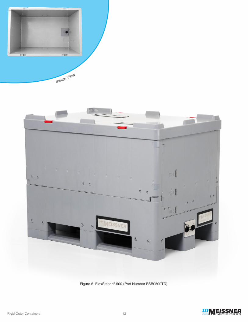
Figure 6. FlexStation® 500 (Part Number FSB0500TD).
Inside View
Rigid Outer Containers 13
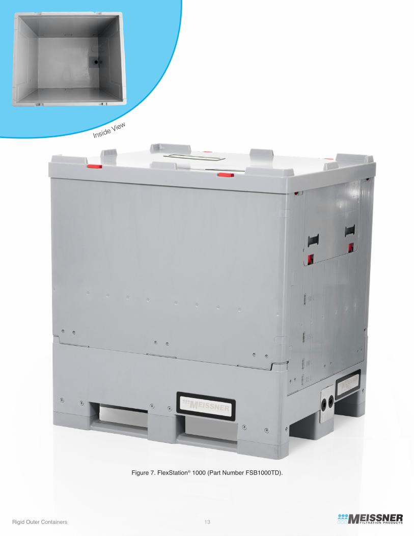
Figure 7. FlexStation® 1000 (Part Number FSB1000TD).
Inside View

Rigid Outer Containers 14
FlexStation®
Part No. Length Width
Outside Dimensions
FSB0100FB31.9 inches(809 mm)
31.9 inches(809 mm)
31.9 inches(809 mm)
47.2 inches(1200 mm)
47.2 inches(1200 mm)
47.2 inches(1200 mm)
24.0 inches(609 mm)
24.0 inches(609 mm)
24.0 inches(609 mm)
31.5 inches(915 mm)
31.5 inches(915 mm)
39.4 inches(1000 mm)
Height(deployed)
32.8 inches(833 mm)
32.8 inches(833 mm)
32.8 inches(833 mm)
36.3 inches(915 mm)
36.3 inches(915 mm)
49.5 inches(1260 mm)
Height(collapsed)
15.9 inches(403 mm)
15.9 inches(403 mm)
15.9 inches(403 mm)
18.5 inches(475 mm)
18.5 inches(475 mm)
18.5 inches(475 mm)
ROC Weight(empty)
66 lbs.(30 kg)
53 lbs.(24 kg)
44 lbs.(20 kg)
225 lbs.(102 kg)
155 lbs. (70 kg)
275 lbs.(125 kg)
FSB0200FB
FSB0200TD
FSB0500BD
FSB0500TD
FSB1000TD
The outer dimensions of the various FlexStation® ROCs as well as their empty weights are presented in the table below.
2. General Dimensional and Weights
Table 2
The primary material of construction in the FlexStation® 100 and 200 are presented in the table below.
The primary material of construction in the FlexStation® 500 and 1000 models are presented in the table below.
3. Materials of Construction
Table 3
Table 4
FlexStation®
Part No.Bin Support Rack
FSB0100FB Polypropylene
Polypropylene
Polypropylene
Polypropylene
304 StainlessSteel
304 StainlessSteel
N/A
Support Tray
N/A
Access Door
ABS
Polypropylene ABS
N/A
Badging
304 StainlessSteel
304 StainlessSteel
304 StainlessSteel
FSB0200FB
FSB0200TD
FlexStation®
Part No.Bin Support Wall
FSB0500BD ABS
ABS
ABS
304 StainlessSteel/ABS
304 StainlessSteel/ABS
304 StainlessSteel/ABS
304 StainlessSteel/ABS
304 StainlessSteel/ABS
304 StainlessSteel/ABS
304 StainlessSteel/ABS
304 StainlessSteel/Aluminum
Support WallHardware Access Door Badging
FSB0500TD
FSB01000TD
N/AN/A
N/AN/A

Rigid Outer Containers 15
Cart Part No.
Applicable FlexStation® Part No. Construction Caster Wheels Features
FSCS02AFSB0100FBFSB0200FBFSB0200TD
FSB0500TDFSB0500BD
FSB0500TDFSB0500BD
FCSL04A
FSCL04B
FSCL11A
FSCL11B
304 Stainless Steel(2) Locking Swivel,
(2) Non-locking Swivel;Stainless steel hardware,
non-marring 5" urethane wheels
(4) Locking Swivel;Stainless steel hardware,
non-marring 5" urethane wheels
(4) Locking Swivel;Stainless steel hardware,
non-marring 5" urethane wheels
(2) Locking Swivel,(2) Non-locking Swivel Fixed;
Stainless steel hardware, non-marring 5" urethane wheels
(2) Locking Swivel,(2) Non-locking Swivel Fixed;
Stainless steel hardware, non-marring 5" urethane wheels
304 Stainless Steel
304 Stainless Steel
304 Stainless Steel
304 Stainless SteelFSB1000TD
FSB1000TD
Removable handle, forkliftaccessible from (2) sides
FSCS02BFSB0100FBFSB0200FBFSB0200TD
304 Stainless Steel(4) Locking Swivel;
Stainless steel hardware,non-maring 5" urethane wheels
Forklift accessible from (4)sides, optional tow bar (see Powered Movers section)
FSCS02CFSB0100FBFSB0200FBFSB0200TD
304 Stainless Steel(2) Locking Swivel,
(2) Non-locking Swivel;Stainless steel hardware,
non-marring 5" urethane wheels
Forklift accessible from (4)sides, optional tow bar (see Powered Movers section)
Forklift accessible from (4) sides, optional tow bar
(see Powered Movers section)
Forklift accessible from (4) sides, optional tow bar
(see Powered Movers section)
Forklift accessible from (4) sides, optional tow bar
(see Powered Movers section)caster configuration
recommended for usage with power assist movers
Forklift accessible from (4) sides, optional tow bar
(see Powered Movers section) caster configuration
recommended for usage with power assist movers
Meissner has carts available for all FlexStation® models as detailed in the table below. All locking casters indicated in table lock both the wheel and the pivot providing a stable and rigid platform to assist in loading and unloading, as well as storage.
1. Carts
C. Optional Features and Accessories
Table 5

Rigid Outer Containers 16
Cart Part No.Applicable
FlexStation®
Part No. Length Width
Cart Dimensions
FSCS02AFSB0100FBFSB0200FBFSB0200TD
FSB0100FBFSB0200FBFSB0200TD
FSB0500TDFSB0500BD
FSB0500TDFSB0500BD
FSB1000TD
FSB1000TD
32 inches(813 mm)
48.4 inches(1229 mm)
48.4 inches(1229 mm)
48.4 inches(1229 mm)
48.4 inches(1229 mm)
25.75 inches(654 mm)
32.6 inches(828 mm)
32.6 inches(828 mm)
40.6 inches(1031 mm)
40.6 inches(1031 mm)
Height(from ground to base
of FlexStation®)
6.75 inches(172 mm)
7.3 inches(185 mm)
7.3 inches(185 mm)
7.3 inches(185 mm)
7.3 inches(185 mm)
Weight(cart only)
30 lbs.(14 kg)
FSCS02B 32.5 inches(826 mm)
24.2 inches(615 mm)
7.3 inches(185 mm)
24.2 inches(615 mm)
7.3 inches(185 mm)
53 lbs.(24 kg)
53 lbs.(24 kg)
32.5 inches(826 mm)
FSB0100FBFSB0200FBFSB0200TD
FSCS02C
70 lbs.(32 kg)
70 lbs.(32 kg)
75 lbs.(34 kg)
75 lbs.(34 kg)
FSCL04A
FSCL04B
FSCL11A
FSCL11B
Additional dimensional information as well as weights for the FlexStation® carts provided in table below.
Table 6

Rigid Outer Containers 17
Load Cell Cart Part No.
Applicable FlexStation® Part No. Construction Caster Wheels Features
FSCS02B-LCFSB0100FBFSB0200FBFSB0200TD
FSB0500TDFSB0500BD
FSB0500TDFSB0500BDFCSL04B-LC
FSCL11A-LC
304 Stainless Steel(4) Locking Swivel;
Stainless steel hardware, non-marring 5" urethane wheels
(2) Locking Swivel,(2) Non-locking Swivel;
Stainless steel hardware, non-marring 5" urethane wheels
(4) Locking Swivel;Stainless steel hardware,
non-marring 5" urethane wheels
304 Stainless Steel
304 Stainless Steel
304 Stainless SteelFSB1000TDFSCL11B-LC
FSB1000TD
Forklift accessible from (3)sides, optional tow bar
(see Powered Movers section)
FSCS02C-LCFSB0100FBFSB0200FBFSB0200TD
304 Stainless Steel(2) Locking Swivel,
(2) Non-locking Swivel;Stainless steel hardware,
non-marring 5" urethane wheels
Forklift accessible from (3)sides, optional tow bar
(see Powered Movers section)
FSCL04A-LC 304 Stainless Steel(4) Locking Swivel;
Stainless steel hardware, non-marring 5" urethane wheels
(2) Locking Swivel,(2) Non-locking Swivel;
Stainless steel hardware, non-marring 5" urethane wheels
Forklift accessible from (3)sides, optional tow bar
(see Powered Movers section)
Forklift accessible from (3) sides, optional tow bar
(see Powered Movers section)caster configuration
recommended for usage with power assist movers
Forklift accessible from (3) sides, optional tow bar
(see Powered Movers section)caster configuration
recommended for usage with power assist movers
Forklift accessible from (3) sides, optional tow bar
(see Powered Movers section)caster configuration
recommended for usage with power assist movers
Meissner also offers a selection of FlexStation® carts with integrated load cells for weight measurement. All carts provide the same display and electronics package for operational consistency, this is summarized in the following table.
2. Carts with Integrated Load Cells
AccuracyTransmitter
Mettler Toledo
Units
lbs or kgs
Capacity
4000 lbs(1815 kgs)
0.1 lb(0.05 kg)
Enclosure Rating
Nema 4x(IP66)
Electrical Requirements
115 V/230 V50/60 Hz
Table 7
Table 8

Rigid Outer Containers 18
Load CellCart Part No.
ApplicableFlexStation®
Part No. Length Width
Cart Dimensions
FSCS02B-LCFSB0100FBFSB0200FBFSB0200TD
FSB0100FBFSB0200FBFSB0200TD
FSB0500TDFSB0500BD
FSB1000TD
32.5 inches(826 mm)
48.8 inches(1239 mm)
48.8 inches(1239 mm)
48.8 inches(1239 mm)
28.6 inches(725 mm)
45.0 inches(1142mm)
45.0 inches(1142mm)
Height(from ground to base
of FlexStation®)
9.81 inches(249 mm)
9.81 inches(249 mm)
9.81 inches(249 mm)
Weight(cart only)
133 lbs.(60 kg)
133 lbs.(60 kg)
156 lbs.(71 kg)
156 lbs.(71 kg)
163 lbs.(74 kg)
163 lbs.(74 kg)
FSCS02C-LC32.5 inches(826 mm)
37.0 inches(939 mm)
9.81 inches(249 mm)
37.0 inches(939 mm)
9.81 inches(249 mm)
28.6 inches(725 mm)
9.81 inches(249 mm)
Height(from ground to top of Load Cell Cart)
33.3 inches(846 mm)
33.3 inches(846 mm)
33.3 inches(846 mm)
33.3 inches(846 mm)
33.3 inches(846 mm)
33.3 inches(846 mm)
48.8 inches(1239 mm)
FSB0500TDFSB0500FBFSCL04A-LC
FSCL04B-LC
FSCL11A-LC
FSCL11B-LC FSB1000TD
Additional dimensional information as well as weights for the FlexStation® carts featuring load cells is provided in table below.
Table 9

Rigid Outer Containers 19
Figure 8. Cart for 100 L and 200 L FlexStation® ROC (Part Number FSCS02A).

Rigid Outer Containers 20
Figure 9. Cart for 100 L and 200 L FlexStation® ROC (Part Number FSCS02B).

Rigid Outer Containers 21
Figure 10. Cart with Load Cells for 100 L and 200 L FlexStation® ROC (Part Number FSCS02B-LC).

Rigid Outer Containers 22
Figure 11. Cart for 500 L FlexStation® ROC (Part Number FSCL04A/B). Note: The FSCL04A is shown and contains (4) swivel casters. The FSCL04B is the same cart, but with (2) swivel and (2) fixed casters as per Table 6.

Rigid Outer Containers 23
Figure 12. Cart for 1000 L FlexStation® ROC (Part Number FSCL11A/B). Note: The FSCL11A is shown and contains (4) swivel casters. The FSCL11B is the same cart, but with (2) swivel and (2) fixed casters as per Table 6.

Rigid Outer Containers 24
Power assisted movers can be useful in conjunction with the FlexStation® carts described in the previous section, especially at the larger scale. Meissner recommends the SmartMover motorized tug for accomplishing this. The smaller cart which is compatible with the FlexStation® 100 and 200, is also compatible with this hardware, while the larger carts that interface with the FlexStation® 500 and FlexStation® 1000 require the adaptor indicated below. Please visit www.meissner.com for photos and additional information pertaining to this option.
3. Powered Movers
Figure 13. Powered mover adapter for the 500 L and 1000 L FlexStation® ROCs (Part Number FSCA-6M01).
Part No.FSCA-6M01
DescriptionAdapter for FSCL xxx Carts

Rigid Outer Containers 25
Figure 14. SmartMover attached to FlexStation® ROC and cart with adapter.

Rigid Outer Containers 26
All FlexStation® ROCs are compatible with pallet jacks. Meissner recommends the use of a short fork model for use with the smaller 100 L and 200 L models.
4. Pallet Jack
Part No.FSPJ01A
DescriptionStainless Steel Pallet Jack for 100 L and 200 L FlexStation® ROC models.
Figure 15. Short fork pallet jack recommended for the 100 L and 200 L FlexStation® ROC models.

Rigid Outer Containers 27
1. ROC Deployment
1. General Recommendations
2. Biocontainer Deployment
3. Assembly Deployment
D. Deployment
E. Intrafacility Applications
Deployment instructions for specific FlexStation® ROCs can be requested through Meissner’s website, your local sales representative or through our Applications Engineering department.
CompatibilityThe compatibility of the various FlexStation® ROCs with possible usage paradigms is presented in the table below. Reference the definitions of the Intrafacility and Interfacility provided on Page 6 of this document. Additional delineation of Interfacility is provided within Table 7 via the terms “Limited” and “Intermediate.” Limited use encompasses infrequent, shorter duration transport, while Intermediate use encompasses longer transport durations and/or through less controlled shipping methods. Please reference the Risk Factors on the following page (Figure 14) for further definition of the variables that impact the delineation between these two terms. Finally, note that Fleet usage is not covered within this document. For inquiries pertaining to this usage paradigm, please contact Meissner.
All standard FlexStation® compatible SUSs are self-deploying. Unless otherwise requested, all custom single-use assemblies designed by our Applications Engineering team will also feature a self-deploying biocontainer. There are videos of various deployments available on the Meissner website at www.meissner.com.
Bottom Drain FunctionalityFlexStation® 100, 200 and 500 “FB” (False Bottom) and “BD” (Bottom Drain) models [part numbers FSB0100FB, FSB0200FB and FSB0500BD] models all feature integrated lower fluid path storage areas. In the 100 and 200 L models this is provided via an integrated lower storage area accessible via a lower door. In the 500 L model this same capacity is provided via a storage area on the side of the bin which communicates with the lower fluid path access area. The FlexStation® 200 “TD” (Top Drain) [part number FSB0200TD] does not have accommodations for bottom porting. The FlexStation® 500 TD and 1000 [part numbers FSB0500TD and FSB1000TD] have lower port access areas to support bottom drain applications, however do not include fluid path storage areas.
Assembly ConsiderationsAll FlexStation® compatible single-use assemblies can be designed with a wide variety of associated fluid paths, integrated sampling systems, etc.
Table 10
FlexStation®
Part No. Intrafacility Use Limited Interfacility Use Intermediate Interfacility Use
Compatible Compatible CompatibleFSB0100FB
Compatible Compatible CompatibleFSB0200FB
Compatible Compatible CompatibleFSB0200TD
Compatible Compatible Limited Compatibility,Reference Risk FactorsFSB0500BD
Compatible Compatible Application Specific,Reference Risk FactorsFSB0500TD
Compatible Not Compatible Not CompatibleFSB01000TD

Rigid Outer Containers 28
Figure 16
Risk FactorsWhen considering interfacility usage of a FlexStation® ROC, the risk factors presented in Figure 14 should be considered. Each unique risk factor is represented as a continuum from lower to higher risk with functional examples provided to illustrate each case. Note: These factors are presented as an aid to help evaluate and mitigate risk associated with interfacility usage of FlexStation® products, and do not represent a quantifiable tool for determining process compatibility. Please contact Meissner with inquiries pertaining to your specific process.
Risk FactorsLower Risk Higher Risk
Risk Continuum
Shipment Method Dedicated transport LTL 2 LTL 2 with multiple cross-dockings
SG 3 = 1 SG 3 > 1 SG 3 >> 1
By trained personnel atcGMP facilities per SOP
Minimal stretch wrapStretch wrapped 5-7 timeswith top covered
Not stacking during transport Stacked in storage
By personnel at cGMPfacilities
Sans ancillary protection
Stacked during transport
By untrained personnel
Fluid Being Shipped
Ancillary Protection
Stacking
Handling
2 LTL: Less Than Truckload shipping, wherein the ROC would be loaded with other dissimilar materials. 3 SG: Specific Gravity.
ISTA 3H TestingThe ISTA 3H testing series is a general simulation test for mechanically handled bulk loads and is thus applicable to the FlexStation® ROCs. It includes horizontal impact testing, rotational flat and edge drops, as well as vibrational testing all performed in a prescribed sequence. Meissner has tested the part numbers indicated below in conjunction with this test. All testing was performed with applicable dunnage using standard TepoFlex® biocontainer assemblies.
2.Qualification
Meissner has performed both International Safe Transit Association (ISTA) as well as real-world distribution testing to qualify the applicable FlexStation® ROCs for interfacility usage.
FlexStation® Part No.FSB0100FBFSB0200FBFSB0500BDFSB0500TD
Replicates Tested4443
Real-World Distribution TestingIn addition to the simulated testing performed via ISTA 3H Meissner has subjected the FlexStation® products to various real-world distribution testing.

Rigid Outer Containers 29
IV. QuaDrum® ROCs
A. Overview
B.Specifications
QuaDrum® ROCs are designed to support intrafacility applications and are available in nominal capacities which support applications between 50 and 200 L. These rectangular ROCs provide a host of benefits over more traditional cylindrical drums which include improved deployment characteristics as well as substantial floor space utilization and improved dynamic stability when deployed on the appropriate dolly.
1. Sizes
QuaDrum® ROCs are available in the nominal sizes represented in the table below. Additionally, indicated therein is information pertaining to the general configuration of these items as well as the maximum applicable volumes that they can be utilized for.
Table 11
4 Note that bottom drain QuaDrum® must be deployed on associated dolly to utilize bottom drain functionality. 5 Volumes represented predicated on usage of appropriate SUS.
QuaDrum®
Part No.Description Configurations 4 Maximum Volumes 5
50 L QuaDrum® Rigid Outer ContainerStandard 50 L configuration, supportstop drain applications
Bottom drain 50 L configuration, supports bottom drain applications
Standard 100 L configuration, supportstop drain applications
Bottom drain 100 L configuration, supports bottom drain applications
Standard 200 L configuration, supportstop drain applications
Bottom drain 200 L configuration, supports bottom drain applications
55 LFASD-050D
50 L QuaDrum® Rigid Outer Container 55 LFASD-050B
100 L QuaDrum® Rigid Outer Container 110 LFASD-100D
100 L QuaDrum® Rigid Outer Container 110 LFASD-100B
200 L QuaDrum® Rigid Outer Container 215 LFASD-200D
200 L QuaDrum® Rigid Outer Container 215 LFASD-200B
3. Assembly Considerations
4. Dunnage
When considering the use of a FlexStation® ROC in an interfacility mode thought should also be given to the associated single-use assembly. This should be mitigated in scope to the extent possible as lengthy fluid paths, extensive componentry, and the like can all serve to exacerbate stress on the assembly during distribution.
Dunnage is required when utilizing the FlexStation® ROCs in an interfacility mode.

Rigid Outer Containers 30
Figure 17. Standard 50 L QuaDrum® ROC, Part Number FASD-050D.
Inside View
Rigid Outer Containers 31
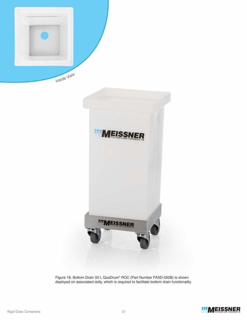
Figure 18. Bottom Drain 50 L QuaDrum® ROC (Part Number FASD-050B) is shown deployed on associated dolly, which is required to facilitate bottom drain functionality.
Inside View

Rigid Outer Containers 32
Figure 19. Standard 100 L QuaDrum® ROC, Part Number FASD-100D.
Inside View

Rigid Outer Containers 33
Figure 20. Bottom Drain 100 L QuaDrum® ROC (Part Number FASD-100B) is shown deployed on associated dolly, which is required to facilitate bottom drain functionality.
Inside View

Rigid Outer Containers 34
Figure 21. Standard 200 L QuaDrum® ROC, Part Number FASD-200D.
Inside View

Rigid Outer Containers 35
Figure 22. Bottom Drain 200 L QuaDrum® ROC (Part Number FASD-200B) is shown deployed on associated dolly, which is required to facilitate bottom drain functionality.
Inside View

Rigid Outer Containers 36
QuaDrum®
Part No. Length Width Height
Outside Dimensions
FASD-050D12 inches(310 mm)
12 inches(310 mm)
18 inches(460 mm)
18 inches(460 mm)
24 inches(610 mm)
24 inches(610 mm)
12 inches(310 mm)
12 inches(310 mm)
12 inches(310 mm)
12 inches(310 mm)
18 inches(460 mm)
18 inches(460 mm)
25 inches(640 mm)
25 inches(640 mm)
31 inches(790 mm)
31 inches(790 mm)
31.5 inches(800 mm)
31.5 inches(800 mm)
ROC Weight(empty)
10.8 lbs.(4.9 kg)
10.8 lbs.(4.9 kg)
16.2 lbs.(7.4 kg)
16.2 lbs.(7.4 kg)
37.2 lbs.(16.9 kg)
37.2 lbs.(16.9 kg)
FASD-050B
FASD-100D
FASD-100B
FASD-200D
FASD-200B
2. General Dimensions and Weighs
The outer dimensions of the various QuaDrum® ROCs as well as their empty weights are presented in the table below.
Table 12
c. Materials of Construction
All QuaDrum® ROCs are molded from the same high quality polyethylene resin.
Rigid Outer Containers 37
Dolly PartNo.
Applicable QuaDrum® Part No.’s
Construction Caster WheelsHeight of Drum
When Deployed on Dolly
Weight(dolly only)
FASC-050C
FASC-050L
FASC-100C
FASC-100L
FASC-200C
FASC-200L
304 Stainless Steel 30.5 inches(770 mm)
17.9 lbs.(8.1 kg)
18.0 lbs.(8.2 kg)
21.1 lbs.(9.6 kg)
21.2 lbs.(9.6 kg)
27.0 lbs.(12.3 kg)
27.1 lbs.(12.3 kg)
30.5 inches(770 mm)
36.5 inches(930 mm)
36.5 inches(930 mm)
37 inches(940 mm)
37 inches(940 mm)
304 Stainless Steel
304 Stainless Steel
304 Stainless Steel
304 Stainless Steel
304 Stainless Steel
FASD-050D,FASD-050B
FASD-050D,FASD-050B
FASD-100D,FASD-100B
FASD-100D,FASD-100B
FASD-200D,FASD-200B
FASD-200D,FASD-200B
(4) Non-locking Swivel;Nickel plated hardware,
non-marring 3" urethane wheels
(4) Locking Swivel;Nickel plated hardware,
non-marring 3" urethane wheels
(4) Non-locking Swivel;Nickel plated hardware,
non-marring 3" urethane wheels
(4) Locking Swivel;Nickel plated hardware,
non-marring 3" urethane wheels
(4) Non-locking Swivel;Nickel plated hardware,
non-marring 3" urethane wheels
(4) Locking Swivel;Nickel plated hardware,
non-marring 3" urethane wheels
Table 13
C. Optional Features and Accessories
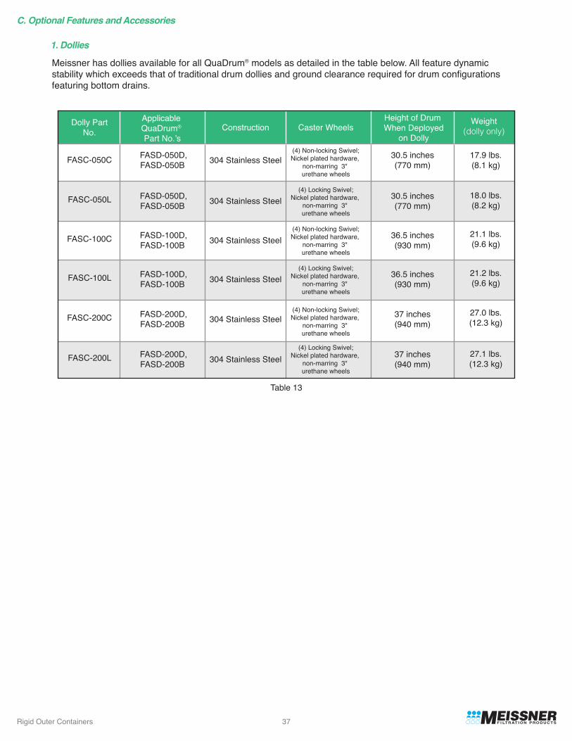
1. Dollies
Meissner has dollies available for all QuaDrum® models as detailed in the table below. All feature dynamicstability which exceeds that of traditional drum dollies and ground clearance required for drum configurationsfeaturing bottom drains.

Rigid Outer Containers 38
Figure 23. Cart for 50 L QuaDrum® ROC (Part Number FASC-050C).

Rigid Outer Containers 39
Figure 24. Cart for 100 L QuaDrum® ROC (Part Number FASC-100L).

Rigid Outer Containers 40
Figure 25. Cart for 200 L QuaDrum® ROC (Part Number FASC-200C).

Rigid Outer Containers 41
Lid Part No. DescriptionApplicable
QuaDrum® PartNo.’s
Construction
FASD-050D,FASD-050B
Polypropylene lid with nylon handleFASD-050L
FASD-050A
FASD-050D,FASD-050B
FASD-050D,FASD-050B
FASD-050R
FASD-100DFASD-100B
FASD-100DFASD-100B
FASD-100DFASD-100B
FASD-100L
FASD-100A
FASD-100R
FASD-200DFASD-200BFASD-200L
FASD-200DFASD-200B
FASD-200DFASD-200B
FASD-200A
50 L QuaDrum® Standard Lid
50 L QuaDrum® Access Lid
50 L QuaDrum® Retaining Lid
100 L QuaDrum® Standard Lid
100 L QuaDrum® Access Lid
100 L QuaDrum® Retaining Lid
200 L QuaDrum® Standard Lid
200 L QuaDrum® Access Lid
200 L QuaDrum® Retaining LidFASD-200R
2. Lids
There are three types of lids available for QuaDrum® ROCs as described below.
The table below features the part number for each of the QuaDrum® lids.
TypeStandard Lid
Access Lid
Retaining Lid
General FunctionalityProvides complete coverage of the top of the QuaDrum® for maximum security during storageProvides access for up to three (3) fluid paths when secured in place such that fluid can be transferred to/from single-use assembly when it is in place.Includes functionality of the Access lid with a retainer for a 3" TC port which positively locates this large bore port during e.g. powder transfer applications.
Table 14

Rigid Outer Containers 42
Figure 26. Standard Lid for the 50 L QuaDrum® ROC (Part Number FASD-050L).
Figure 27. Standard Lid for the 50 L QuaDrum® ROC (Part Number FASD-050L) shown in use.

Rigid Outer Containers 43
Figure 28. Retaining Lid for the 100 L QuaDrum® ROC (Part Number FASD-100R).
Figure 29. Retaining Lid for the 100 L QuaDrum® ROC (Part Number FASD-100R) shown in use.

Rigid Outer Containers 44
Figure 30. Access Lid for the 200 L QuaDrum® ROC (Part Number FASD-200A).
Figure 31. Access Lid for the 200 L QuaDrum® ROC (Part Number FASD-200A) shown in use.

Rigid Outer Containers 45
NominalVolume Length Width Projected
Footprint Diameter ProjectedFootprint 6
QuaDrum® Traditional Cylindrical Drum
50 L
Typical Reductionin Floor SpaceProvided by QuaDrum®
100 L
200 L
12 inches(310 mm)
12 inches(310 mm)
144 inches2
(929 cm2)
18 inches(460 mm)
12 inches(310 mm)
216 inches2
(139.4 cm2)
24 inches(610 mm)
13 inches(330 mm)
18 inches(460 mm)
22 inches(560 mm)
169 inches2
(1090 cm2)17%
50%
12%
324 inches2
(2090 cm2)
484 inches2
(3122 cm2)18 inches(460 mm)
432 inches2
(278.7 cm2)
D. Deployment
1. ROC Deployment
2. Biocontainer Deployment
3. Assembly Deployment
Deployment instructions for specific QuaDrum® ROCs can be requested through Meissner’s website, your local sales representative or through our Applications Engineering department.
All QuaDrum® compatible SUSs deploy in the traditional manner as described herein, however given the rectangular footprint of these drums, deployment is both simpler and much more repeatable relative to typical cylindrical drums. There are videos of various deployments available on the Meissner website at www.meissner.com.
Bottom Drain FunctionalityThose QuaDrum® ROCs which feature a bottom drain must be deployed on the associated dolly in order to take advantage of this functionality. When deployed on the dolly, clearance is available at the bottom of the ROC which allows the bottom fluid path to be deployed. Note however that there is no fluid path storage provided and thus care must be used when moving the drum/dolly combination with a bottom fluid path deployed. Lid UseWhen an Access lid is being used in conjunction with a QuaDrum® and applicable SUS it is recommended that the biocontainer be filled at least half way before initially installing the lid to allow for fill monitoring and prevent fluid path entrapment. When a Retaining lid is being used, the 3" TC port can typically be installed after only a few liters of fluid have been added to the biocontainer as this positively locates the top of the biocontainer relative to the ROC.Assembly ConsiderationsAll QuaDrum® compatible single-use assemblies can be designed with a wide variety of associated fluid paths, integrated sampling systems, etc.
E. Operational Footprint Considerations
As compared to traditional cylindrical drums, QuaDrum® ROCs feature a number of benefits as described herein. The table below expounds upon the reduction in floor space that can be achieved via utilization of these items.
Table 15
6 Projected area us calculated at Diameter x Diameter, as this accurately represents floor space consumed by cylindrical drum in typical application.

1001 Flynn Road • Camarillo, CA 93012 • USA+1.805.388.9911 • +1.805.388.5948 Fax
www.meissner.com
FlexStation® and QuaDrum® are registered trademarks of Meissner Filtration Products. © 2016 Meissner Filtration Products, Inc. All rights reserved.GD0015-1.4