
RIGID LIFT - Carga Fácilcargafacil.com/Biblioteca/pdf/volteo/MANUALINSTVOLTEOING.pdfRIGID LIFT...
28
RIGID LIFT INSTALLATION & OPERATION MANUAL MODELS: RL-B10 THRU RL-L125 THIS MANUAL IS TO BE USED IN CONJUNCTION WITH THE APPROPRIATE PUMP INSTALLATION MANUAL AND HOIST PARTS LIST. Harsh International, Inc. 600 Oak Ave. Eaton, CO 80615 (970)-454-2291 Fax: (970)-454-3491 Price: $2.50 Manual Part Number: 102685G IMPORTANT FAILURE TO COMPLETE THE ENCLOSED WARRANTY CERTIFICATE MAY VOID YOUR WARRANTY IF YOU NEED ASSISTANCE CALL 1-800-227-1702
Transcript of RIGID LIFT - Carga Fácilcargafacil.com/Biblioteca/pdf/volteo/MANUALINSTVOLTEOING.pdfRIGID LIFT...

RIGID LIFT
INSTALLATION & OPERATIONMANUAL
MODELS: RL-B10 THRU RL-L125
THIS MANUAL IS TO BE USED IN CONJUNCTION WITH THE APPROPRIATE PUMP INSTALLATION MANUAL AND HOIST PARTS LIST.
Harsh International, Inc.600 Oak Ave.
Eaton, CO 80615(970)-454-2291
Fax: (970)-454-3491
Price: $2.50 Manual Part Number: 102685G
IMPORTANTFAILURE TO COMPLETE
THE ENCLOSED WARRANTY CERTIFICATE MAY VOID
YOUR
WARRANTY IF YOU NEED ASSISTANCE CALL
1-800-227-1702

Congratulations on your recent purchase of a Harsh Hoist! This manual is only a small part of Harsh’s continuing effort to serve their customers and bring the best products pos-sible to you the customer. If you have any questions or experience any problems contact your local Harsh Distributor or the Harsh Factory.
Harsh International, Inc.600 Oak AvenueEaton, CO 80615(970) 454-2291
Fax: (970) 454-3491
NOTES:
1) For single axle trucks, tail hinge placement is based on 32 inches from the center lineof the tail hinge pin to the center line of the truck axle with a 2 inch clearance betweenthe cab and bed. For tandem axle trucks, the center of the tail hinge pin is mounted0 to 2 inches forward from the back edge of the rear tire. This is based on a length of44 inches from the center of the trunnion to the center of the tail hinge pin. Overhangis measured from the center pin on the tail hinge to the rear of the bed. Tire size andsuspension configuration may cause these measurements to vary.
2) The calculated capacity, in tons, is for the body and payload together with an evenlydistributed, non-diminishing, solid load for the full cycle. The center (center of gravity)of the load is assumed to be at the center of the body. To insure adequate hoistcapacity you should take into account the type of material, and how it will be loaded.The capacities will be reduced if the body is loaded more to the front then to the rearor if part of the load behind the tail hinge is unloaded prior to raising the hoist.
2

3
Table of Contents
NOTES.............................................................................................................................2IMPORTANT INFORMATION...........................................................................................4INSTALLATION FACTS....................................................................................................5INSTALLATION PROCEDURES.................................................................................6-13FIGURE 1: SUB FRAME...................................................................................................6FIGURE 2: TAIL HINGE PLACEMENT.............................................................................6FIGURE 3: TANDEM AXLES............................................................................................6FIGURE 4: NOTCHING FRAME.......................................................................................7FIGURE 5: LOWER MOUNT GUIDE TABS......................................................................7FIGURE 6: MOUNT LOCATIONS.....................................................................................8FIGURE 7: ATTACHING MOUNT ANGLES.....................................................................9FIGURE 8: SUPPORT ANGLES.......................................................................................9FIGURE 9: JACK STAND PLACEMENT..........................................................................9FIGURE 10: BOARD PLACEMENT................................................................................10FIGURE 11: VERTICAL PLATE ASSEMBLY.................................................................10FIGURE 12: DIAGONAL PLATE.....................................................................................11FIGURE 13: STRINGER ATTACHMENT PLATE...........................................................11FIGURE 14: WELDING UPPER MOUNT.......................................................................11FIGURE 15: BLEEDER SCREW LOCATION.................................................................12FIGURE 16: BALL SEAL.................................................................................................12SAFETY PROP INSTALLATION...............................................................................14-17FIGURE 17: SAFETY PROP DIMENSIONS...................................................................14FIGURE 18: TOP PIN PLATE ASSEMBLY.....................................................................14FIGURE 19: SAFETY PROP ASSEMBLY......................................................................15FIGURE 20: BOTTOM SUPPORT ANGLE POSITION...................................................15FIGURE 21: SIDE PLATE AND STOP PEG POSITION.................................................16FIGURE 22: LATCHING BRACKET LOCATION............................................................17SAFETY PROP OPERATION.........................................................................................18SAFETY INSTRUCTIONS..............................................................................................19OPERATION INSTRUCTIONS..................................................................................20,21MAINTENANCE INSTRUCTIONS..................................................................................22TROUBLESHOOTING....................................................................................................23CYLINDER REWORK INSTRUCTIONS.........................................................................24ASSEMBLED DRIVE LINE INSTALLATION INSTRUCTIONS.......................................25

IMPORTANT INFORMATION
This manual has been prepared to provide the owner and operator with the information required to properly operate and maintain the unit. It is important that you, the owner or operator, read this manual prior to operating or performing any maintenance work on the unit.For your convenience, we have provided this space for you to record your model andserial numbers and date of purchase as well as your dealership name and address.
Some of the information below is needed for ordering parts. Please fill in informa-tion for faster service when ordering.
This hoist was shipped with a HARSH WARRANTY VALIDATION CERTIFICATION card.This certification card must be completely filled out and returned to HARSH prior to anywarranty being processed. If you did not receive this certification card please contactHARSH.
Owners Name:
Owners Address:
Model Number:
Serial Number:
Purchase Date:
Dealer Name:
Dealer Address:
Dealer Telephone Number:
4

INSTALLATION FACTS
1. The hoist can be mounted with theScissor Hinge either fore or aft formounting versatility.2. Plan how the hoist, safety prop, andpump will fit on the truck. The mountingarea of the hoist must be free from thecross members, air tanks, etc. for correctmounting3. The hoist upper mounts sit upbetween the bed cross sills. It may benecessary to shift the hoist fore or aftslightly to avoid cutting or moving thebed cross sills. This will slightly effectthe tipping angle and capacity. If thetruck frame width is to wide you mustbuild a suitable subframe for the hoist tomount on as you cannot pull the hoistmounts out of the hoist tubes more then1/4 inch.4. Determine where the PTO and pumpcan be located. The pump position willdetermine how the hoist can beplumbed. Also, keep the cylinder(s),pump, and reservoir away from heatsources such as exhaust pipes.5. Tilt cab trucks may require greatercab to bed clearance. This is necessaryto allow the truck cab (when tilted) toclear the bed. Also any obstruction (aircleaner stack, exhaust pipes, etc.) mustbe two inches or more from the bedbeing installed.
6. Take time to become familiar with allhoist parts and how they are to bemounted. Take notice how the mountsare banded for shipping. This is howthe hoist is mounted.7. All work should be done by qualifiedpersonnel.8. Insure that this Manual along with thePump Installation Manual and HoistParts Manual are forwarded to the enduser.9. Never modify the hoist or pump in anyway. Install the hoist according to theInstallation Manual, and Parts Manual forthe specific model of hoist.10. These instructions are for typicalinstallations. If your requirements aredifferent due to body and truck configu-ration, it is the responsibility of theinstaller to insure the installation is com-pleted correctly. Before beginning theinstallation you should always review allappropriate technical manuals and infor-mation from the truck chassis manufac-turer, trade organizations, and otherapplicable sources.11. Never install a double acting hoist(power up & power down) as a singleacting hoist (power up only). Thesehoists have been designed and tested asdouble acting hoists and modification ofthe plumbing to use them as a single act-ing hoist can result in excessive pressurebuild up inside the cylinder which maylead to cylinder failure and possible dam-age to the hoist, body, truck, and/or per-sonal injury.
READ ALL PROVIDED MATERIAL AND SAFETY INSTRUCTIONS BEFORE INSTALLING HOIST!
5

INSTALLATION PROCEDURES
Figu
1. Remove the box from the truck frame.Construct a subframe or filler blocks fortrucks with frames too wide or those thatdo not have a straight frame (pickups)(see Figure 1). In the following instruc-tions, the subframe will be referred to asthe truck frame for this type of truck.
2. To install the tail hinge assembly,determine where the tail hinge will beplaced for your truck. For single axletrucks, the distance from the front of thetail hinge to the rear spring hangershould be 4 to 6 inches (see Figure 2).The distance from the axle to the centerof the tail hinge should be approximately32 inches; allowing clearance for mudflap brackets.
For a tandem axle truck the tail hinge is
mounted as follows. The distance fromthe center of the pivot pin, on the hingeassembly, to the rear edge of the rear tireshould be 0 to 2 inches (see Figure 3). Ifthe truck has a rear spring hanger thedistance from the front of the tail hinge tothe spring hanger should be 4-6 inches.This placement will give a distance ofapproximately 44 inches from the centerof the trunnion to the center of the tailhinge pin. The tail hinge is placed closeto the axle to avoid frame damage andsevere weight transfer from the frontaxles when dumping.
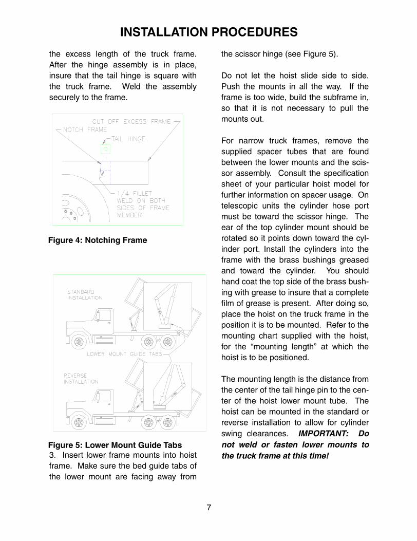
After placement of the tail hinge is deter-mined cut out the top rear section of theframe, in which the tail hinge will set(see Figure 4). The hinge should bemounted flush with the top and end ofthe frame. It may be necessary to cut off
WARNING:Always use suitable stands,and hoisting or lifting equip-ment when lifting the hoist,body or other heavy items.
Figure 2: Tail Hinge Placement
Figure 3: Tandem Axles
re 1: Sub-Frame
6
INSTALLATION PROCEDURES
the excess length of the truck frame.After the hinge assembly is in place,insure that the tail hinge is square withthe truck frame. Weld the assemblysecurely to the frame.
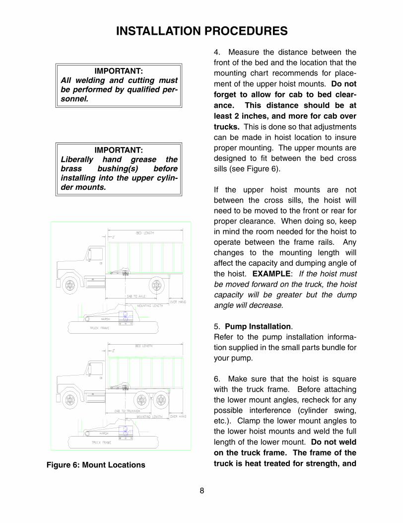
3. Insert lower frame mounts into hoistframe. Make sure the bed guide tabs ofthe lower mount are facing away from
the scissor hinge (see Figure 5).
Do not let the hoist slide side to side.Push the mounts in all the way. If theframe is too wide, build the subframe in,so that it is not necessary to pull themounts out.
For narrow truck frames, remove thesupplied spacer tubes that are foundbetween the lower mounts and the scis-sor assembly. Consult the specificationsheet of your particular hoist model forfurther information on spacer usage. Ontelescopic units the cylinder hose portmust be toward the scissor hinge. Theear of the top cylinder mount should berotated so it points down toward the cyl-inder port. Install the cylinders into theframe with the brass bushings greasedand toward the cylinder. You shouldhand coat the top side of the brass bush-ing with grease to insure that a completefilm of grease is present. After doing so,place the hoist on the truck frame in theposition it is to be mounted. Refer to themounting chart supplied with the hoist,for the “mounting length” at which thehoist is to be positioned.
The mounting length is the distance fromthe center of the tail hinge pin to the cen-ter of the hoist lower mount tube. Thehoist can be mounted in the standard orreverse installation to allow for cylinderswing clearances. IMPORTANT: Donot weld or fasten lower mounts tothe truck frame at this time!
Figure 4: Notching Frame
Figure 5: Lower Mount Guide Tabs
7
INSTALLATION PROCEDURES
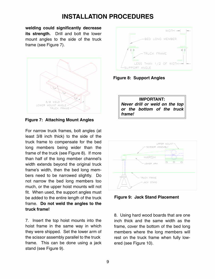
4. Measure the distance between thefront of the bed and the location that themounting chart recommends for place-ment of the upper hoist mounts. Do notforget to allow for cab to bed clear-ance. This distance should be atleast 2 inches, and more for cab overtrucks. This is done so that adjustmentscan be made in hoist location to insureproper mounting. The upper mounts aredesigned to fit between the bed crosssills (see Figure 6).
If the upper hoist mounts are notbetween the cross sills, the hoist willneed to be moved to the front or rear forproper clearance. When doing so, keepin mind the room needed for the hoist tooperate between the frame rails. Anychanges to the mounting length willaffect the capacity and dumping angle ofthe hoist. EXAMPLE: If the hoist mustbe moved forward on the truck, the hoistcapacity will be greater but the dumpangle will decrease.
5. Pump Installation.Refer to the pump installation informa-tion supplied in the small parts bundle foryour pump.
6. Make sure that the hoist is squarewith the truck frame. Before attachingthe lower mount angles, recheck for anypossible interference (cylinder swing,etc.). Clamp the lower mount angles tothe lower hoist mounts and weld the fulllength of the lower mount. Do not weldon the truck frame. The frame of thetruck is heat treated for strength, and
IMPORTANT:All welding and cutting mustbe performed by qualified per-sonnel.
IMPORTANT:Liberally hand grease thebrass bushing(s) beforeinstalling into the upper cylin-der mounts.
Figure 6: Mount Locations
8
INSTALLATION PROCEDURES
welding could significantly decreaseits strength. Drill and bolt the lowermount angles to the side of the truckframe (see Figure 7).
For narrow truck frames, bolt angles (atleast 3/8 inch thick) to the side of thetruck frame to compensate for the bedlong members being wider than theframe of the truck (see Figure 8). If morethan half of the long member channel’swidth extends beyond the original truckframe’s width, then the bed long mem-bers need to be narrowed slightly. Donot narrow the bed long members toomuch, or the upper hoist mounts will notfit. When used, the support angles mustbe added to the entire length of the truckframe. Do not weld the angles to thetruck frame!
7. Insert the top hoist mounts into thehoist frame in the same way in whichthey were shipped. Set the lower arm ofthe scissor assembly parallel to the truck frame. This can be done using a jackstand (see Figure 9).
8. Using hard wood boards that are oneinch thick and the same width as theframe, cover the bottom of the bed longmembers where the long members willrest on the truck frame when fully low-ered (see Figure 10).
IMPORTANT:Never drill or weld on the topor the bottom of the truckframe!
Figure 8: Support Angles
Figure 9: Jack Stand Placement
Figure 7: Attaching Mount Angles
9

INSTALLATION PROCEDURES
Drill and bolt the boards in place withcarriage bolts that are recessed into thewood. By doing this the weight of thebed and the load is distributed acrossthe length of the truck frame and is notconcentrated on a few points. On com-pleted installations there should be agap between the upper and lowermounts from the use of the wood spacer.This is acceptable, because it distributesthe load over the full length of the truckframe, preventing a concentrated load atthe mounting point.
9. Lower the truck bed onto the truckframe, positioning it exactly as it will bemounted when lowered. Weld the verti-cal plate assembly of the tail hinge to thelong member of the bed with the pininserted in the tail hinge assembly (seeFigure 11). Insure that the vertical plateassemblies are installed correctly asshown. It may be necessary to installsome washers as spacers between thepin bushings and the vertical plates tohelp center the body and keep it frommoving from side to side.
10. There are two methods to attach theupper hoist mount to the bed long mem-ber. One method is to bolt the uppermount to the long member. The othermethod is to weld the upper mount to thelong member.
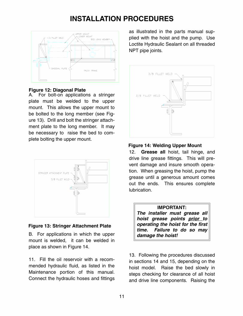
Both methods require a 1/4 inch diago-nal plate installed to the long member,centered on the upper mount location(see Figure 12). This will prevent thelong member from rolling under. Thisplate is furnished by the installer due tothe variety of long member sizes.
Figure 11: Vertical Plate Assembly
Figure 10: Board Placement
10
INSTALLATION PROCEDURES
A. For bolt-on applications a stringerplate must be welded to the uppermount. This allows the upper mount tobe bolted to the long member (see Fig-ure 13). Drill and bolt the stringer attach-ment plate to the long member. It maybe necessary to raise the bed to com-plete bolting the upper mount.
B. For applications in which the uppermount is welded, it can be welded inplace as shown in Figure 14.
11. Fill the oil reservoir with a recom-mended hydraulic fluid, as listed in theMaintenance portion of this manual.Connect the hydraulic hoses and fittings
as illustrated in the parts manual sup-plied with the hoist and the pump. UseLoctite Hydraulic Sealant on all threadedNPT pipe joints.
12. Grease all hoist, tail hinge, anddrive line grease fittings. This will pre-vent damage and insure smooth opera-tion. When greasing the hoist, pump thegrease until a generous amount comesout the ends. This ensures completelubrication.
13. Following the procedures discussedin sections 14 and 15, depending on thehoist model. Raise the bed slowly insteps checking for clearance of all hoistand drive line components. Raising the
IMPORTANT:The installer must grease allhoist grease points prior tooperating the hoist for the firsttime. Failure to do so maydamage the hoist!
Figure 14: Welding Upper Mount
Figure 12: Diagonal Plate
Figure 13: Stringer Attachment Plate
11

INSTALLATION PROCEDURES
hoist and stopping it in several positionsto check for clearance will help preventdamage to the truck and hoist. Areas tocheck include: the pump, the PTO driveshaft, cylinder swing, top mounts, bedcross sills, tail hinge, etc. See the Oper-ation portion of this manual for operationinstructions that apply to your hoist.
14. Single Acting Cylinders: For sin-gle acting (power up only) cylinderhoists, complete the steps in this section.If the hoist is operated with no clearanceproblems then raise the hoist until fullyextended. Support the bed with a suit-able overhead hoist to prevent lower-ing of the truck bed. With the pumprunning, and the control knob in the raiseposition, loosen the bleeder screw (atthe top of the cylinder) one half turn toallow the air to escape (see Figure 15).
Do not remove the bleeder screw orthe ball may be lost (see Figure 16).When the air and foam stops escapingfrom the bleeder screw, and the fluid isclear, retighten the bleeder screw.Unhook the overhead hoist and lower the
truck bed.
15. Double Acting Cylinders: Forhoists designed as double acting (powerup and power down) complete the stepsin this section. If the hoist is operatingwith no clearance problems, then raisethe hoist to half of the possible dumpangle. Support the bed with a suitableoverhead hoist to prevent lowering ofthe truck bed. Fill the hydraulic tank 3/4full with hydraulic fluid. Continue to raisethe hoist fully. Unhook the overheadhoist and lower the truck bed.
16. Raise and lower the hoist severaltimes. Check the hydraulic fluid in thereservoir according to the pump installa-tion instructions.17. All installations must include asafety prop. To install a safety prop on
WARNING:Insure the safety prop isinstalled on all applications!
IMPORTANT:Never modify a double actingcylinder to use as a single act-ing cylinder! Serious damageto the cylinder may occur!
Figure 16: Ball Seal
Figure 15: Bleeder Screw Location
12

INSTALLATION PROCEDURES
the truck, raise the unloaded body to theapproximate desired height. When thedesired height is reached, securelybrace the truck body in this position witha suitable support or overhead hoist.During the installation you will be work-ing under the body. Do not depend onthe hoist hydraulic system to hold thebody up. External hoists and/or rigidbody braces between the truck frameand the body could be used to provideadditional support. Whichever method isused, it must be capable of holding thebody up if the hoist hydraulic systemshould fail. Remember the safety propis only intended to support an emptybody and is not intended to be usedwith a loaded body. If it is necessary towork on a unit, the body must beunloaded prior to using the safety prop.
A single safety prop is usually adequatefor bodies 16 foot and shorter. Twosafety props should be used on bodieslonger than 16 foot, one on each side ofthe body. The safety prop is designed tooperate on either or both sides of thetruck. It will also operate in front of, orbehind the hoist mounts. The safetyprop should be located so it will clear allexternal obstructions, such as the fueltank, air tank, battery box, fenders, etc.The figures show the safety propinstalled on the left hand side (driversside) of the truck. When installing twosafety props, they must make contactwith the bottom support angle at thesame time. The bottom support angle isshipped unwelded so you may install iton either side. Insure that the open
end of both support angles is towardthe front of the truck.
All welding should be performed by aqualified welder who is familiar with thistype of welding. Remember the weightof the unloaded body must be supportedby this safety prop. Therefore you willwant to insure that the welding will beadequate.
For assembled drive line installationinstructions, see page 25.
13

SAFETY PROP INSTALLATION
SAFETY PROP INSTALLATION INSTRUCTIONS.
1. Raise the empty box, and brace up box. The Top Pin Plate Assembly should beclamped to the box long members. (The plate assembly should be flush with the topof the box long member). Hang the Safety Prop on the pin and with the Prop hangingstraight down, hold the dimensions as shown in Figure 17.
NOTE: a. Brace up the box while working under it.b. The Safety Prop may be mounted on either forward or aft of the hoist
lower mount.c. The Safety Prop will swing forward to the latching storage position, there-
fore you must insure that you have adequate clearance for this swing.
2. Weld the Top Pin Plate Assembly to the box long member (see Figure 18). Removethe weld splatter from the pin.
Figure 17: Safety Prop Dimensions
Figure 18: Top Pin Plate Assembly
14

SAFETY PROP INSTALLATION
3. Assemble the washers and Safety Prop to the Top Pin and weld as shown inFigure 19.
4. Clamp the Bottom Support Angle in position as shown in Figure 20.
NOTE: The Safety Prop must be hanging vertical with the truck level.
Figure 19: Safety Prop Assembly
Figure 20: Bottom Support Angle Position
15
SAFETY PROP INSTALLATION
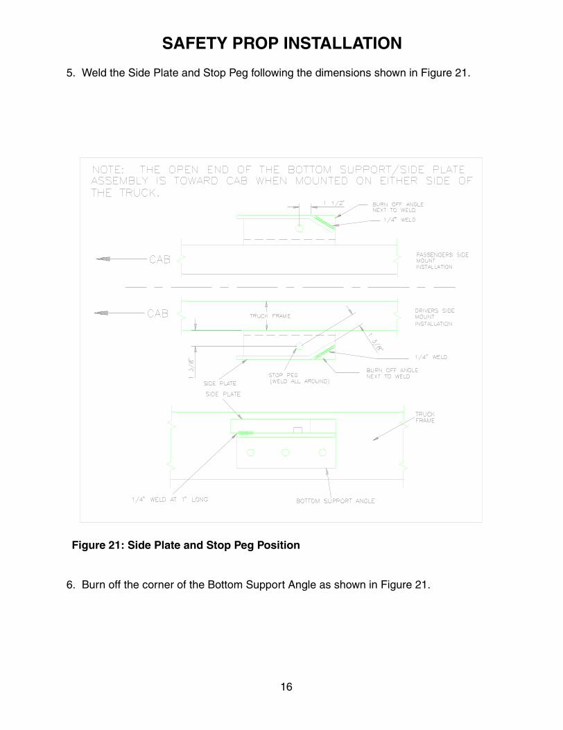
5. Weld the Side Plate and Stop Peg following the dimensions shown in Figure 21.
6. Burn off the corner of the Bottom Support Angle as shown in Figure 21.
Figure 21: Side Plate and Stop Peg Position
16
SAFETY PROP INSTALLATION
7. Drill and bolt the Bottom Support Angle in place. (See Figure 20.)
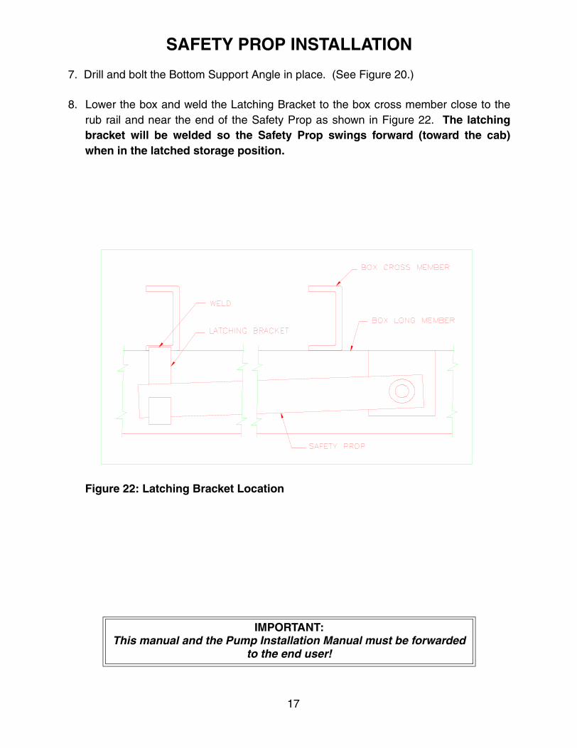
8. Lower the box and weld the Latching Bracket to the box cross member close to therub rail and near the end of the Safety Prop as shown in Figure 22. The latchingbracket will be welded so the Safety Prop swings forward (toward the cab)when in the latched storage position.
IMPORTANT:This manual and the Pump Installation Manual must be forwarded
to the end user!
Figure 22: Latching Bracket Location
17

SAFETY PROP OPERATION
Once the Safety Prop installation is complete, it can be operated as follows:
A. The Safety Prop should be unlatched from the latching bracket. Once unlatched,the Safety Prop should hang down.
B. Raise the body until the Safety Prop slides into the bottom support angle abovethe stop peg. Do not raise the body too far or it will allow the Safety Prop to gopast the bottom support angle.
C. Slowly lower the body back down until the Safety Prop rests firmly on the bottomsupport angle (over the stop peg).
D. To release the Safety Prop, raise the body several inches until the box prop swingsup and past the bottom support angle. The body can then be lowered completelydown to the truck frame. When lowering, insure that there are no obstructionsin the swing path of the Safety Prop. If an interference or obstruction isencountered, stop the lowering process and swing the Safety Prop up intothe latching bracket.
E. Once the body is fully down, swing the Safety Prop up into the latching bracket.
WARNING:Use the Safety Prop only with an empty box. The Safety Prop is
not designed to support a loaded box! If it is necessary to work on a box it must be unloaded first.
18

SAFETY INSTRUCTIONS
1. Always insure the Hoist Control in the cab works free and is in good operating order.The controls must be clearly marked for function and operation.
2. Always check for overhead wires, obstructions, and people before raising the hoist.
3. Dump with the truck at rest, on level ground and with a balanced load. The Rigid Liftdesign gives added stability over other hoist designs in normal dumping operations.The hoist is not designed to operate in extreme conditions.
4. The operator must stay in the cab, at the controls during the duration of the dumpingcycle. If there are bystanders around the dumping area, the operator must have anoutside observer present to insure that all bystanders are a safe distance away.
5. Never permit anyone under a loaded dump bed.
6. Bring a loaded dump body down slowly by easing the control knob inward. On doubleacting cylinders, make sure the pump is running when doing so or the reservoir mayover flow. Resulting in the loss of fluid and allowing air into the system.
7. Always use the safety prop to secure the dump bed up before any maintenance orinspection is performed under the empty dump body as specified by the safety decalsprovided by Harsh International, Inc. The safety prop is not designed or intended forsupporting a loaded body. If repairs or maintenance is needed, you must unload thebody before attempting any repairs.
8. Observe all PTO safety instructions provided by the PTO manufacturer as well asthose listed in the hoist information.
A. Do not go under the vehicle when the engine is running.B. Do not work on PTO or shaft when the engine is running.C. Do not engage or disengage the PTO or driven equipment by hand from under the
vehicle when the engine is running.
NOTE: For assembled drive line installation instructions see page 25.
19

OPERATION INSTRUCTIONS
1. Operation warnings.
A. Do not operate hoist while truck is moving.B. Make sure all loads are level in the truck bed.C. Do not dump loads while on uneven or unstable ground.D. Never operate PTO pump over the rated speed.(check with pump manufacture for
maximum speeds.E. Disengage PTO while driving truck to prevent pump damage.F. Do not increase the pump pressure. Serious damage could occur if increased
above the rated setting.G. If the hoist is a power down hoist (double acting cylinders) do not continue to send
power to lower hoist after the bed is fully lowered. Damage to the truck and thehoist could occur.
H. Never allow hoist to bounce or jerk when stopping the hoist movement.
2A. To raise and lower a control cable hoist.A. Set the emergency/parking brake.B. Put the truck in park or neutral. Check area around truck for clearance.C. Engage PTO shaft while the engine is idling. For electric pumps have the engine
running to charge the battery.D. Press the centering button on the control and activate the valve to full up position
to raise the hoist.E. Warning: Do not exceed the pumps RPM rating at the shaft.F. To stop the hoist at any position while raising, position the control to the center
position G. Stopping the hoist just before the cylinder(s) are fully extended will help to
increase the life of the hoist and pump.H. To lower the hoist, have the pump running, press the centering button, and posi-
tion the control to the lowering position. The pump must be operating and thevalve must be fully activated when lowering a two way hoist. This allows the pumpto return hydraulic fluid to the top of the cylinder. Failure to follow this procedurewill overflow the reservoir and allow air and contamination to enter the system.On electric pumps, make sure the pump motor is running while lowering the hoistor the pump may be damaged.
I. To stop the hoist from lowering, slowly return the control to the center position.Always make sure that the lever is centered when the box is fully lowered.
J. Never allow the hoist to bounce or jerk when stopping hoist movement. This couldcause serious damage to the truck frame and the hoist. This could also void thewarranty due to misuse of the hoist.
20

OPERATION INSTRUCTIONS
2B. To raise and lower an electric switch control hoist.
A. Keep the truck running to charge the battery.B. Set the emergency/parking brake.C. Put the truck in park or neutral.D. Press the “up” button or the toggle switch on the control box to “up”, to raise the
hoist.E. Release the control button to stop the hoist at any position while raising.F. Stopping the hoist just before the cylinder(s) are fully extended will help to increase
the life of the hoist and pump.G. To lower the hoist, press the “down” button or toggle switch to “down”.H. To stop the hoist while lowering, release the button or toggle switch.I. Never allow the hoist to bounce or jerk when stopping hoist movement. This could
cause serious damage to the truck frame and the hoist. This could also void thewarranty due to misuse of the hoist.
J. Units with an electric pump have an internal flow control located in the lowering cir-cut. This is installed to slow the lowering speed of the hoist and prevent the over-flowing of the tank with the return oil. This also allows sufficient oil to be pumpedinto the top of the cylinder.
21

MAINTENANCE INSTRUCTIONS
1. Periodic maintenance and inspection will increase hoist life. Check all bolts, cotterpins, hydraulic lines, hydraulic reservoir level, scissor assembly, universal joints, anddrive line components every 50 hoist cycles or weekly whichever comes first.
2. Lubricate all grease fittings before using the hoist the first time and every 50 hoistcycles there after. Greasing the hoist will prevent hoist damage and help to maintainlifting capacity. Severe conditions may require more frequent servicing.
3. Change the hydraulic oil when it becomes dirty or at least once every 12 months.Dirty oil causes increased seal wear and oil leakage. The following recommendedhydraulic oils were selected based on the following characteristics. Their ability toraise the hoist in a minimum amount of time, as well as, anti-corrosion, anti-wear, andanti-foaming properties.
IMPORTANT NOTICE ALWAYS USE THE OIL RECOMMENDED BY THE PUMP MANUFACTURE. IF NO
SPECIFIC OIL HAS BEEN RECOMMENDED BY THE PUMP MANUFACTURETHEN YOU CAN USE ONE OF THE FOLLOWING.A. Approved all weather oils: Texaco - Aircraft Hydraulic Oil 15
Shell - Aeroshell Fluid 4Exxon - Univis J43
B. The following oils or equivalent are acceptable at temperatures above freezing:
Texaco Brands: Rando HD 32Texamatic DexronTexamatic F
Co-Op: Automatic Transmission Oil DexronAutomatic Transmission Oil F
4. Field repair of hydraulic components should not be attempted. This would includehydraulic cylinders, valves, and pumps. These components should be sent to aHarsh dealer-distributor. Seals and o-rings on hydraulic cylinders should only beinstalled by a qualified hydraulic specialist. New parts can be obtained from yourHarsh dealer-distributor. Insure that the complete hydraulic system is flushed afterany component failure.
5. Harsh does not supply weld-on components for the scissor assembly. If damageoccurs, Harsh recommends replacement of the entire scissor assembly.
22

TROUBLESHOOTING
1. The hoist will not raise smoothly:A. Air in the cylinders. (Refer to Installation sections 14 and 15.)B. Lubricate hoist and tail hinge.
2. Failure to raise load properly:A. Release bed tie-downs.B. Hoist capacity has been exceeded. (See page 2, Notes:)C. Blocked or pinched hydraulic line.D. Control valve is not moving the full stroke, reducing the hoist speed.E. The pump intake is blocked from dirty oil or oil that is too thick for cold weather.F. Pump is not operating because the PTO shaft is not turning or the pump is bad.
Have the pump checked by your local Harsh dealer or the Harsh Factory.
3. Failure to raise the hoist fully:A. Check the hydraulic oil level in the reservoir.B. Air in the cylinder(s). (Refer to Installation sections 14 and 15.)C. Lubricate the hoist components.
4. Failure to lower hoist:A. Control valve is not moving the full stroke.B. Check for blocked or pinched hydraulic lines.C. Lubricate the hoist components.
5. Oil leakage:A. Check all fittings and hoses. Contact your local Harsh dealer to order replace-
ment hoses and fittings. Use only hoses and fittings supplied by Harsh.B. Gland nut leaking, may require cylinder repair. Contact your local Harsh dealer.
6. Oil spilling out the reservoir tank:A. Oil foaming caused by oil that is too thick, or air in the hydraulic lines. Cycle the
hoist several times and bleed the air out of the cylinder(s). (Refer to Installationsections 14 and 15.)
B. PTO was not engaged during lowering.C. The body weight is too great, causing the hoist to lower too rapidly. A flow control
valve must be installed in this situation.
7. The hoist raises very slow:A. The oil is too thick for cold weather.B. A hydraulic line is partially blocked or pinched.C. The filter screen is dirty.D. The pump is worn or defective.E. Control valve is not moving the full stroke.
23

CYLINDER REWORK INSTRUCTIONS
1. Special Equipment Required:A. Bronze coated or brass vise or vise inserts.B. Hydraulic pressure available.C. Gland nut and piston spanner wrenches.
2. General:A. Whenever clamping on a surface that moves past an o-ring or seal, extra care
must be taken to prevent nicks, scratches, and deformation.B. All parts that have scores or nicks on moving surfaces should be replaced with
new parts.C. Keep the cylinder parts very clean when reassembling.
3. Disassembly:A. Extend cylinder stages either manually or with hydraulic pressure.
WARNING: Never use air pressure to extend stages or cylinders!B. Clamp on the cylinder body with a vise and unscrew the gland nut on the cylinder
body.C. Remove the gland nut with the cylinder rod or tube.D. For telescopic or multiple stage cylinders, continue loosening gland nuts and
removing smaller stages one at a time. WARNING: Do not use pipe wrenches or other tools that will damage orscratch cylinder rods and tubes.
E. Remove the gland nut(s) from the cylinder rod or tubes.F. Remove all o-rings, backup rings, stop rings, and wear rings. Hint: Keeping all
parts to a gland nut, piston, or cylinder tube together will help to identify parts.This will make the reassembly of the cylinder easier.
G. Clean all metal parts and dry them thoroughly.H. Install all o-rings, backup rings, stop rings, and wear rings using clean grease to
hold parts in place if necessary. Grease all o-rings before installing them. Besure to have all parts fully seated in their respective grooves before attemptingfinal assembly.
I. Oil all moving parts: piston, cylinder rod, cylinder tubes, etc.J. Assemble all gland nuts on their respective cylinder tubes.K. Reassemble cylinder in the reverse order that it was disassembled. Tighten all
gland nuts as you go. When reassembling the cylinder top mount, use Loctite290.CAUTION: Make sure not to damage o-rings, seals, etc. when assemblingcylinder.
L. The cylinder is now ready to install in the hoist assembly.
24

ASSEMBLED DRIVE LINE INSTALLATION
When installing the pump and drive line attempt to position the pump so the face of thepump shaft is 46 inches from the face of the PTO output shaft. This will allow installationof the assembled drive line without having to adjust its length. If it is not possible tomount the pump in this location, the installer will need to shorten the shaft following theprocedures listed below.
Insure that the pump is mounted to provide the necessary clearance for the driveline and shield to rotate without interference from any obstructions.
Measure the actual distance from the face of the pump shaft to the face of the PTO shaft.Subtract this measurement from 46 inches. The difference is the amount that thedrive line must be shortened. Both the inner and outer shields as well as the hex shaftmust be shortened by this amount.
A. Pull the two halves of the drive line apart.
B. Cut the necessary amount off the end of the inner and outer plastic tubes.
C. Cut the same amount off the end of the hex shaft and chamfer the end of theshaft. Be careful not to damage the plastic shields during the shortening pro-cess as this may interfere with the proper operation of the shield.
D. Slide the assembly back together and install the drive line on the unit.
E. Grease the drive line.
FOLLOW ALL OTHER INSTALLATION PROCEDURES SHOWN IN THE INSTALLATION MANUAL.
25

NOTES
26

NOTES
27