Rigid and Flexible Pipes
8
ncb TECHNOLOGY:: - , ----[JJ illIc[f'ffrim WUb
-
Upload
limin-zhang -
Category
Documents
-
view
100 -
download
1
description
Rigid Flexible Pipe
Transcript of Rigid and Flexible Pipes
ncb TECHNOLOGY::
~-'..J - " ~"",, ,----[JJ ~ illIc[f'ffrim WUb ~ \1D~rmID~

Rigid and Flexible Pipes An Objective Understanding of Pipe-Soil Interaction,
Design and Installation By Shah Rahman
[IDuried pipelines for the conveyance of potable water o and sanitary sewers form the bedrock of our civiliza
tion.The very baSic services that we take for granted , such as a running faucet with clean drinking water and the ability of our wastewater to be transported away from our homes and businesses for treatment and release into the envirolUnent, are possible because of the vast network of buried pipes that lie hidden beneath roads and the concrete jungles that define the large urban centers that are our cities.
These intricate networks consist of various types of pipe materials that range from metals to concrete to plastics to composites. Whatever the material type, all are expected to provide some minimum service qualities: prevention of leaks, which ensure that potable water isn't compromised by contaminants entering a piping system and that wastewaters do not pollute soils and existing sources of groundwater, and most importantly, that the structural soundness of a buried pipe system results in a minimum service life of 50 to 100 years. The latter can only be ensured through a thorough understanding of and designing for ·the loa'ds to which a buried pipe will be exposed, its response to the loading, and the interaction mechanism between the pipe and surrounding soils.
While an understanding of pipe-soil interaction is important for the sound structural design of pipelines, it should be noted that the concern for soil pressure on a pipe is linlited to empty pipe or gravity flow pipelines where the conduit never flows full . In municipal pressure piping systems, the internal pressure is typically much greater than soil pressure on the pipe; internal pressure essentially supports the soil load when the line is placed into service.
The story of tlle formal study of buried pipe structures in orth America begins in Ames, Iowa, at the turn of the 20m
Century, when Dr.Anson Marston, then Dean of Engineering at the Iowa State College (now Iowa State University) and the first Chairman of the Iowa State Highway CommisSion, analyzed oil pressures on buried culverts in an effort to drain muddy rural roads. Research was also necessary as mousands of small wooden bridges were being replaced by concrete and clay pipes placed in stream beds underneath roadway embankments. It was necessary to design them properly so that they would not fail .
Buried pipe deSign, then, was inextricably connected to the development of highway systems in the United States. Marston was the first Chairman of the federal Highway Research Board. Our knowledge of pipe-soil interaction, as well as the development of new pipe materials and the improvement of traditional ones, has grown by leaps and bounds since those early days, leading to a multi-billion dol-
36 TRENCHlESS TECHNOLOGY November 2010
lar global pipe materials industry. Another relatively new construction method in buried pipeline construction and rehabilitation is the advent of trenchless technology.
While trenchless technology is no longer' in its infancy, the only known and practiced trenchless construction methods during Marston's lifetime included jacking and tunneling, and little else. But a tremendous anlount of research in the last two decades now provides design engineers and contractors with an understanding of the pipesoil mechanics of pipelines built by methods other than traditional open-trench methods.
Classical Pipe-Soil Interaction Theory In 1913, and 1930, Marston published his original
papers "The Theory of Loads on Pipes in Ditches and Tests of Cement and Clay Drain Tile and Sewer Pipe" and "The Theory of External Loads on Closed Conduits in the Light of the Latest Experiments ," respectively, marking the earliest systematic approach of studying the structural mechanics of buried pipes. Thus was defined the MarstonTheory of Loads on buried conduitsThis became, in part, the very foundation on which much of the later work around the world on earth loading technology of buried pipes was based. In 1941 , Marston 's student Merlin Spangler, known today as "the father of buried flexible pipe design ," published another ground-breaking paper, "The Structural Design of Flexible Pipe Culverts ," in which he derived an equation, the Iowa Formula, for predicting the ring deflection of buried flexible pipes. Spangler would later become chairman of the Culvert Committee of the federal Transportation Research Board . In 1958, Spangler's student, Reynold Watkins , published "Some Characteristics of the Modulus of Passive Resistance of Soil - A study in Similitude," in which he solved a fundamental flaw in the dimensions of a modulus of passive resistance in Spangler's Iowa Formula, defUling a new modulus of horizontal soil reaction, E', in the Modified Iowa Equation. In later years , other significant contributions came from A. Howard, ]. Duncan, ]. Hartley, F. Heger, T. McGrath, M. Zargbamee, and others that now enable the external load design of rigid and flexible pipes to be an even more exact science . ..,
The Marston Load Theory In his analysis of external loads on buried pipe, Marston
defined two main types of loading conditions of buried pipes, a ditch conduit (referred to as trench load condition in present day nomenclature), and a projecting conduit (referred to as an embankment condition in present day literature), Table 1.
www.trenchlessonline.com

Table 1: Marston's Buried Pipe Installa tionlLoadine Conditions load of the central prism due to the direction in which the shearing stresses or friction forces develop as a result of the differential settlement of tl1e central prism in relation to the external prisms. Pipes that display this behavior when buried are referred to as Flexible Pipes. Use of the prism load is conservative because installers do not compact soil against the pipe. The pipe is embedded in a "packing" of less dense soil that erves the same way as does packing around an item in a shipping container. The pipe is relieved of part of the prism load which the soil then picks up in arching action over the pipe.
Marston's Present Day
Conduit Description Diagra m Installation Type
Nomenclature
Ditch Conduit I Trench Load Condition Ditch Conduit Trench Load Pipe is installed in a narrow trench
N.anlcroundMoril(t g Condition (generally', trench width :::; 2 x pipe diameter) in undisturbed soil, then
r backfi lled to natural ground surface level
Proiecting Conduit I Embankment Condition Positive Projecting Positive Pipe is installed underneath an "" .. -.-",..,--.-
Conduit Embankment embankment, in shallow bedding, Condition t wi its top projecting above the
-0-Positive surface of the natural ground Projecting ..... ""'" Embankment
Negative Projecting Negative Pipe is instal led underneath an ·ropol£m~1Il
Conduit Embankment embankment, in narrow and """"''''''''' Condition I shallow trench with its top at an lOr As a general rule, flexible pipes
will deflect at least 2 percent without structural distress. Most flexible pipe material standards allow up to 5 percent deflection. Deflection is limited to 2 percent if the flexible pipe has a rigid lining and coating and 3 percent for a rigid lining and flexible coating. Flexible pipes include steel, duc-
Negative elevation below natural ground Projecting surface Embankment
Imperfect Ditch Induced Trench Special case, similar to Negative ... ~-[)o;c-.d""'~'ffI
Conduit Condition Embankment Condition, but more ....... --,----..40r-
favorable from standpoint of load ' I ll_w
reduction on pipe, used in very ..
deep installations. Di ffi cult to .~
achieve for large-diameter pipes.
The basic concept of the Marston Load Theory is that the load on a buried pipe, because of the weight of the column of soil , or central prism, directly above the pipe, is modified by the response of the pipe and the relative movement of the side columns of oil, or external prisms (adjacent to the pipe, between the pipe and the trench walls on either side), to the central prism. The relative movement of the central prism and the side prisms result in shearing stresses or frictional forces , calculated using Rankine's theory.
Rigid Pipe Marston recognized that in a trench (generally, trench
width ~ 2 x pipe diameter), when the side columns of soil or the external prism are more compressible than the pipe due to its inherent rigidity, this causes the pipe to assume load generated across the width of the trench.The shearing stresses or friction forces that develop due to the differential settlement of the external prisms and tl1e central prism are additive to the load of the central prism alone. Pipes that behave in this manner are referred to as Rigid Pipes. Generally, rigid pipes start showing signs of structural distress before being vertically deflected 2 percent. Rigid pipes include reinforced non-cylinder concrete, reinforced concrete cylinder, prestressed concrete cylinder, vitrified clay, polymer concrete, cast iron, asbestos cement and castin-place pipes.
Flexible Pipe On the other hand, if a pipe is more compressible than
the external soil COJtU11l1S, without any structural damage caused to the pipe as a result of its vertical deflection allowing the central prism to settle more in relation to th~ external prisms, the actual load on the pipe is less than the
www.trenchlessonline.com
. tile iron, thermoplastics such as Polyvinyl Chloride (PVC) and High
Density Polyethylene (HDPE) , thermosetting plastics such as fiberglass-reinforced polymer (FRP), bar-wrapped concrete cylinder pipe, and corrugated steel pipes.
Semi-Rigid Pipe Some pipe materials exhibit characteristics of both rigid
and flexible pipes, primarily controlled by tl1eir diameters, and are referred to as semi-rigid. Attempts have been made to define semi-rigid pipes as those that will deflect between 0.1 percent and 3.0 percent without causing harmful or potentially harmful cracks. Bar-wrapped concrete cylinder pipe is an example. But sin<:e current design standards are based on the concept of a rigid or a flexible pipe, the term carries only marketing value and little else. Like all flexible buried pipes, bar-wrapped concrete cylinder pipe design is al 0 subject to a deflection limit, thus making it a flexible pipe.
Pipe-Soil Interaction in Embankment Conditions A positive embankment installation condition, where the
pipe is installed underneath an embankment, in shallow bedding, with its top projecting above the surface of the natural ground, is another commonly-encol1l1tered scenario for buried pipe design and installation. The loads and shearing forces just di cussed for trench conditions also play a key role in embankment conditions. As indicated in figure 3a and 3b, the imaginary vertical planes extending upward from the sides of a buried pipe are the planes along which relative movements are aSStU11ed to occur and on which shearing forces are generated. pB c is the vertical distance from the natural ground surface to the t~p of the structure, where p is the projection ratio, the vertICal distance between the top of the pipe and the
November 2010 TRENCHLESS TECHNOLOGY 37
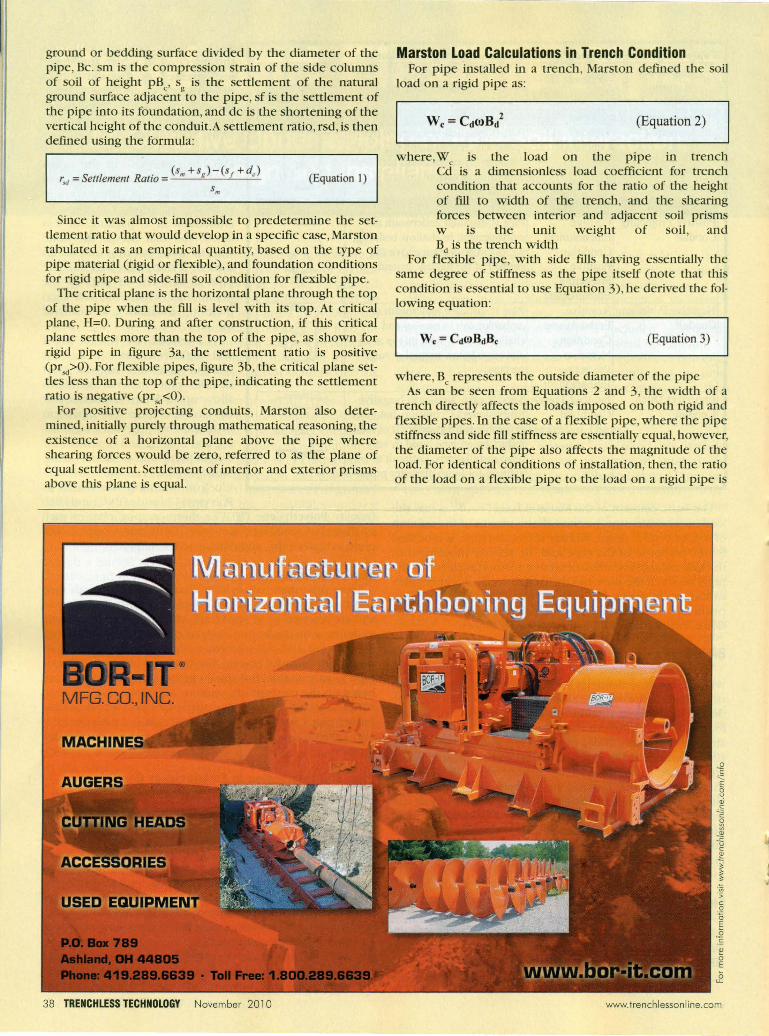
ground or bedding surface divided by the diameter of the pipe, Be. sm is the compression strain of the side columns of soil of height pB , s is the settlement of the natural
e g ground surface adjacent to the pipe, sf is the settlement of the pipe into its foundation, and dc is the shortening of the vertical height of the conduit.A settlement ratio , rsd, is then defined using the formula:
rsd = Settlement Ratio (Equation 1)
Since it was almost impossible to predetermine the settlement ratio that would develop in a specific case, Marston tabulated it as an empirical quantity, based on the type of pipe material (rigid or flexible) , and foundation conditions for rigid pipe and side-fill soil condition for flexible pipe.
The critical plane is the horizontal plane through the top of the pipe when the fill is level with its top. At critical plane, H=O. During and after construction, if this critical plane settles more than the top of the pipe, as shown for rigid pipe in figure 3a, the settlement ratio is positive (prsd>O). For flexible pipes, figure 3b, the critical plane settles less than the top of the pipe, indicating the settlement ratio is negative (prsd<O).
For positive projecting conduits, Marston also determined, initially purely through matllematical reasoning, the existence of a horizontal plane above the pipe where shearing forces would be zero, referred to as the p lane of equal settlement. Settlement of interior and exterior prisms above this plane is equal.
38 TRENCHLESS TECHNOLOGY November 2010
Marston Load Calculations in Trench Condition For pipe installed in a trench, Marston defmed the soil
load on a rigid pipe as:
(Equation 2)
where,Wc
is the load on the pipe in trench Cd is a dimensionless load coefficient for trench condition that accounts for the ratio of the height of fill to widli of the trench, and the shearing forces between interior and adjacent soil prisms w is the unit weight of soil , and B d is the trench widtn
For flexible pipe, with side fills having essentially the same degree of stiffness as the pipe itself (note that this condition is essential to use Equation 3), he derived the following equation:
(Equation 3)
where, Be represents the outside diameter of the pipe As can be seen from Equations 2 and 3, the width of a
trendl directly affects the loads imposed on both rigid and flexible pipes. In the case of a flexible pipe, where lie pipe stiffness and side fill stiffness are essentially equal, however, the diameter of the pipe also affects the magnitude of the load. For identical conditions of installation, then, the ratio of the load on a flexible pipe to the load on a rigid pipe is
.;;;
.:; c:
.Q "0 E
.2 S ~ o E
www.trenchlessonline.com

equal to the ratio of the pipe diameter to the width bf the trench.
(We) Rigid Pipe
(We )Flexible Pipe C droBd·B e
If the trench is twice as wide as the buried pipe, the load imposed on a rigid pipe will be twice the load imposed on a flexible pipe with side fills having the same degree of stiffness as the flexible pipe itself.
Load Calculations in Embankment Condition For pipe installed under an embankment, Marston derived
another formula, equation 4.
(Equation 4)
where Wc is the load on the pipe under embankment Cc is a dimensionless load coefficient for embankment condition that accounts for the ratio of the height of fill to pipe diameter, the shearing forces between interior and adjacent soil prisms, and the direction and amount of relative settlement between interior and adjacent soil prisms
w is the unit weight of soil , and Bc is the pipe diameter
Since tllere is no trench by definition of a positive embankment condition, the trench width, B
d, is not a part of equa
tion 4 . For Cc' when the product of tlle settlement ratio, rsd , and the projection ratio, p, equals zero, i.e. prSd = 0, then Cc = HIBc' If this is substituted into Equation 4, the load on a pipe underneath an embankment is defmed as
(Equation 5)
where, H is the burial depth of the pipe
Equation 5 is referred to as the prism 10ad.As stated earlier, for rigid pipes, settlement ratio under an embankment is positive (pr",>O) and for flexible pipes, settlement ratio is negative (pr",<O). The condition prsd = 0 for flexible pipe is therefore conservative and is the maximum load that will be imposed by soil on a flexible pipe in virtually all cases. In practice, for design purposes, under bOtll trench and embankment conditions, the prism load is always used for flexible pipes.
Pipe in Wide Trenches Equation 2 for rigid pipes indicates that the load on buried
pipe is directly related to tile trench width, i.e. the wider the trench, the higher tile 10ad.TIus relationship between trench widti1 and load is applicable and equation 2 for trench conclition can be used for all trench widths below that wluch gives a load equal to tile load indicated by equation 4 for a positive embankment conclition. The width at which tile load equality for ti1e two equations develops is referred to as tile transition widtll.The embankment equation (4) must be used for rigid pipes beyond ti1e transition width.
40 TRENCHLESS TECHNOLOGY November 2010
Corroboration of Marston Load Marston 's observations of load on buried pipe were vali
dated in a 21-year study, from 1927 to 1948, where concrete, cast iron (both rigid pipes) and corrugated steel pipes (flexible pipe) were buried under an embankment of 15 ft . Measured loads on the pipes were compared with loads calculated by the Marston theory of loads on underground conduits, and were found to closely agree. Figure 4 presents measured loads on the concrete and corrugated steel pipe. It can be seen that the load on the concrete pipe was consistently 50 percent greater than that on the corrugated steel pipe of approxinlately the same diameter.TIus load difference can be attributed to the difference in vertical deflection of the pipes that influenced the settlement ratios, and the magnitude of the shear stress components, as correctly theorized by Marston for flexible and rigid pipe materials. His assertion that the load on a rigid pipe would always be higher than the load on a flexible pipe due to the differences in interaction between each type of pipe with surrounding soils was therefore corroborated . The study also verified the presence of a plane of equal settlement which Marston had originally predicted purely based on mathematical reasoning.
<: +---+--+-l'20
~ , --+-f-±--I----t-t...,j'oo ~6~==~~ __ -k~~~
L--~-----L-~~~S~'~~'~,~'~,lP nOletyrl !
.Figure 4: Soil Load Differences in Rigid and Flexible Pipes in 21-Year Study
Trenchless Technology In recent years, the challenges of constructing new or reha
bilitating old buried pipeline infrastructure in lughly developed urban areas has lead to ti1e development of various construction and renewal meti10ds ti1at avoid lie cutting of trenches and cause mininlal surface intrusion. Generally referred to as trenchless tec1mology, ti1ese meliods include directional drilling, microtunneling, pipe jacking, auger boring, sliplining, pipe bursting, and oti1ers. The load on a jacked or tll11l1eled conduit, can be described as:
(Equation 6)
where,Wt is ti1e load on a jacked or tll1111eled pipe C, is a dimensionless load coefficient for tunneled or jacked
pipe w is the unit weight of soil , and B is the maximum width of bore excavation
'is the cohesion of the soil above the excavation The vertical load at the top of the bore within the width
of lie excavation is tlle upward friction forces and tile soil cohesion along the limits of the soil prism directly above the
wWw.trenchlessonline.com
bore subtracted from the weight of the prism above the bore. The 2
eC,B, in Equation 6 represents the cohesion of undis
mrbed soils. In North America, the field of horizontal directional drilling
(HDD) has made significant progress due to extensive research by Tom Iseley, referred by some as "the father of trenchless technology," Ray Sterling, Larry Petroff, Mohammed Najafi, SamuelAriaratnum, Larry Slavin, Erez AIIouche,Alan Atalah, Ian Moore, Mark Knight and others. HDD is the most widely utilized method of trend1kss constmction in North America. ASTM F1962, Standard Guide for Use of Maxi-Horizontal Directional Drilling for Placement of Polyethylene Pipe or Conduit Under Obstacles, including River Crossings, provides an understanding of earth loading pressures and subsequent pipe deflection for thermoplastics such as HDPE when installed by HDD.
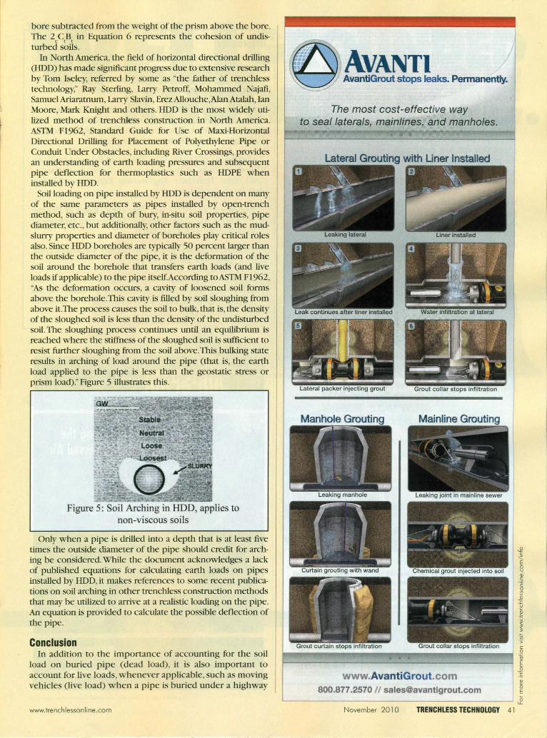
Soil loading on pipe installed by HDD is dependent on many of the same parameters as pipes installed by open-trench method, such as depth of bury, ill-situ soil properties, pipe diameter, etc. , but additionally, other factors such as the mudslurry properties and diameter of boreholes play critical roles also. Since HDD boreholes are typically 50 percent larger than the outside diameter of the pipe, it is the deformation of the soil around the borehole that transfers earth loads (and live loads if applicable) to the pipe itself.According toASTM F1962, "As the deformation occurs, a cavity of loosened soil forms above the borehole. This cavity is filled by soil sloughing from above it.The process causes the soil to bulk, that is, the density of the sloughed soil is less than the density of the lmdisturbed soil. The sloughing process continues lmtil an equilibrilun is reached where the stiffness of the sloughed soil is sufficient to resist further sloughing from the soil above. This bulkillg state results in archillg of load around the pipe (that is, the earth load applied to the pipe is less than the geostatic stress or prism load)." Figure 5 illustrates this.
Figure 5: Soil Arching in HOD, applies to non-viscous soi ls
Only when a pipe is drilled into a depth that is at least five times the outside diameter of the pipe should credit for archillg be considered. While the doclUnent acknowledges a lack of published equations for calculating earth loads on pipes installed by HDD, it makes references to some recent publications on soil archillg in other trenchless constmction methods that may be utilized to arrive at a realistic loading on the pipe. An equation is provided to calculate the possible deflection of the pipe.
Conclusion In addition to the importance of accounting for the soil
load on buried pipe (dead load), it is also important to accOlmt for live loads, whenever applicable, such as moving vehicles (live load) when a pipe is buried lUlder a highway
www.trenchlessonline.com
The most cost-effective way to seal laterals, mainlines, and manholes.
Lateral Grouting with Uner Installed
.;;; '> c:
.Q
" r-----------------------------------------~ E www.AvantiGrout.com
800.877 .2570 1/ [email protected]
J! .!: i':' o E L-__________________________________________ ~
November 2010 TRENCH LESS TECHNOLOGY 41

or railroad embankment. One way in which this is done is by u e of modified Boussinesq equations, details of which were not discussed in this article.
It is important to remember that the concern for soil pressure on a pipe is limited to empty pipe or gravity flow pipelines where the conduit never flows fuU . In municipal pressure piping systems, where the internal pressure is typically much greater than external soil pressure, the former supports the latter when the line is placed into service. For larger diameter flexible pressure pipelines however, it is always appropriate to run a check that the soil conditions are appropriate to limit the pipe 's allowable vertical deflection as permitted by specification and to prevent any damage to rigid linings and/or coatings due to excessive deflection.
The value of soil load analysis is to arrive at the required pipe strength necessary to build a municipal pipeline of sufficient structural integrity to serve its design life. The design process varies from rigid to flexible pipe, and usually by pipe material also. The second part of this series in the next issue will review current design practices for rigid and flexible pipes with regards to earth loading.
Shoh Rahman is the western regional engineer for Northwest Pipe Co., based in Southern Cal if. He is an Associate Editor (Pipe Materials) for the ASCE Journal of Pipeline Systems Engineering and Practice.
STOP INFILTRATION AND INFLOW with (U ES Truck-mounted TV / Inspection / Grout I
Lateral Reinstatement Systems
Eliminate costly Infiltration and inflow (1&1) with CUES custom truck·mounted TV/Grout systems for condition assessment and Joint sealing of wastewater lines and lateral services. If relining or point repair Is required, add a lateral reinstatement system! Pipe Inspection operations and the resultant rehabilitation action are facilitated by one Integrated mobile system. Contact CUES for a discussion and demonstration!
For more inlormotion visit www./renchlesson/ine.com/ inlo
42 TRENCHLESS TECHNOLOGY November 2010
References ASTM (2005), "Standard Guide for Use of Maxi-Horizontal
Directional Drilling for Placement of Polyethylene Pipe or Conduit under Obstacles, Including River Crossings,"P1962-05,ASTM International, West Conshohocken, PA
Marston, M. G. , and A. o.Anderson (1913), "The Theory of Loads on Pipes in Ditches and Tests of Cement and Clay Drain Tile and Sewer Pipe,"Iowa State University Engineering Experiment Station, Bulletin 31 ,Ames, Iowa
Marston, M. G. (1930), "The Theory of External Loads on Closed Conduits in the Ligllt of the Latest Experiments," Iowa State University Engineering Experiment Station, Bulletin 96,Ames, Iowa
Spangler, M. G. (1941), "The Structww Design of Flexible Pipe Culverts,"Iowa State University Engilleering Experiment Station, Bulletin 153,Ames, Iowa
Spangler, M. G. , and R. L. Handy (1982), Soil Engineering, 4dJ ed., ew York: Harper & Row
Watkins, R. K. and M. G. Spangler (1958), "Some Characteristics of dJe Modulus of Passive Resistance of Soil - A study in SinJilitude," Proceedings Highway Research Board 39: 389-397
For more mformalton or 10 dl~cuss the bcnef,h of u~lflg .==:- t.r!rrrvxll7iY~· on AIR SPADE on your next prolect please conloel our ~E~~~t1fAV~ Clr exctlvoflon experts
800-482-7324 C:UAftlll'#¥H!~ .. rlcksweet@OIr spade com · www air spade C0m ~
For more informo/ion visit www./renchlesson/ine.com/ inlo
www.trenchlessonline.com

The Trenchless Technology magazine article “Rigid and Flexible Pipes: An objective Understanding of Pipe-Soil Interaction, Design and Installation,” published in the November 2010 issue (Vol. 19, No. 11), has several missing figures that were originally submitted to the Editor by the Author, but could not be published due to lack of space. In particular, Figures 3a and 3b, mentioned in the article but not included, are critical to understanding some of the equations that are discussed. These two figures appear below:
Figure 3a, 3b: Embankment Condition Soil Loading in Rigid Pipe, in Flexible Pipe
Furthermore, the two additional figures shown below, will be helpful in obtaining a better understanding of the Marston Load Theory, as well as the differences between Rigid and Flexible pipes, as discussed in the article.
Response to Soil Loading in Trench of Rigid Pipe, of Flexible Pipe


![Rigid , Semi Rigid & Flexible Ducting - Holyoakeattachments.holyoake.com/products/files/Spiro-Set[1172].pdf · Rigid , Semi Rigid & Flexible Ducting ... Pressure Drop Per Metre Length](https://static.fdocuments.in/doc/165x107/5a9e3c667f8b9a36788d1100/rigid-semi-rigid-flexible-ducting-1172pdfrigid-semi-rigid-flexible-ducting.jpg)