Rights / License: Research Collection In Copyright - … · 2017-08-30 · ing thedrug release ......
155
Research Collection Doctoral Thesis Novel strategies and technologies for the aseptic microencapsulation of pharmaceutical compounds Author(s): Freitas, Sergio L.P. Publication Date: 2005 Permanent Link: https://doi.org/10.3929/ethz-a-005069007 Rights / License: In Copyright - Non-Commercial Use Permitted This page was generated automatically upon download from the ETH Zurich Research Collection . For more information please consult the Terms of use . ETH Library
Transcript of Rights / License: Research Collection In Copyright - … · 2017-08-30 · ing thedrug release ......
Research Collection
Doctoral Thesis
Novel strategies and technologies for the asepticmicroencapsulation of pharmaceutical compounds
Author(s): Freitas, Sergio L.P.
Publication Date: 2005
Permanent Link: https://doi.org/10.3929/ethz-a-005069007
Rights / License: In Copyright - Non-Commercial Use Permitted
This page was generated automatically upon download from the ETH Zurich Research Collection. For moreinformation please consult the Terms of use.
ETH Library

Diss. ETH No. 16012
Novel strategies and technologies for the aseptic
microencapsulation of pharmaceutical compounds
A dissertation submitted to the
Swiss Federal Institute of Technology Zurich
for the degree of
Doctor of Natural Sciences
presented by
Sergio LP. Freitas
Chemical Engineer, Technische Universität Clausthal
Born November 24th 1973
Citizen of the Federal Republic of Germany
Accepted on the recommendation of
Prof. Dr. HP, Merkle, examiner
PD Dr. B. Gander, co-examiner
Prof. Dr. J.P. Benoit, co-examiner
2005

Contents
CONTENTS
Background and purpose 1
Abstract 5
Zusammenfassung 9
Chapter I 13
Microencapsulation by solvent extraction/evaporation: reviewing the state of the
art of microsphere preparation process technology
Chapter II 55
Continuous contact- and contamination-free ultrasonic emulsification - a useful
tool for pharmaceutical development and production
Chapter III 77
Solvent extraction employing a static micromixer: a simple, robust and versatile
technology for the microencapsulation of proteins
Chapter IV 107
Flow-through ultrasonic emulsification combined with static micromixing for
aseptic production of microspheres by solvent extraction
Chapter V 121
Ultrasonic atomisation into reduced pressure atmosphere - envisaging aseptic
spray-drying for microencapsulation
Discussion and outlook 145
Curriculum Vitae 149
Publications 149
Acknowledgements 151

Background and purpose 1
Background and purpose
Biodegradable microspheres have been intensively studied as delivery
systems for low and high molecular weight bioactive compounds throughout the
last two decades. Considered primarily for parenteral and pulmonary admini¬
stration, they offer a number of potential benefits: Controlled and sustained re¬
lease of the encapsulated bioactive material, protection of the non-released ma¬
terial from degradation and physiological clearance, and adjuvancy for encapsu¬
lated immunoreactive compounds. Biodegradable microspheres are of special
interest for the formulation of fragile, highly active molecules with relatively short
biological half-life such as peptides and proteins, or of molecules that require
targeted delivery into cells or the nucleus such as oligonucleotides and DNA [1].
Poly(lactic acid), PLA, and poly(lactic-co-glycolic acid), PLGA, are the
most frequently employed materials in the formulation of biodegradable micro¬
spheres. These polyesters are highly biocompatible and degrade at controlled
rates into the metabolic products lactic acid and glycolic acid [2,3]. PLA and
PLGA microspheres with microencapsulated bioactive compounds are generally
produced by either of three basic processes or their numerous variants, which
are the so-called solvent extraction/evaporation, phase separation (coacerva-
tion) and spray drying. Spray-drying is a continuous process with high through¬
put, but may not be compatible with temperature-sensitive compounds. Yields
for small batches are moderate [4], and achievable particle sizes limited by the
specifications of the particular equipment. Phase separation, a batch process,
yields relatively high encapsulation efficiencies for water-soluble compounds,
but is impaired by organic process solvent residues in the microspheres [5].
Furthermore, it is not well suited for producing microspheres in the low mi¬
crometer range. Finally, solvent extraction/evaporation offers mild processing
conditions and good control of the particle size from tens or hundreds of mi¬
crometers down to the nanometer range, but requires thorough selection of ma¬
terials and encapsulation conditions to yield efficient encapsulation and low sol¬
vent residues (see Chapter I).
The considerable number of microsphere formulations emerging from the
labs brought forth the need to prepare such particles in larger quantities and
safe and reliable quality for clinical trials and commercialisation. Lab scale pro-

2 Background and purpose
duction processes frequently are inappropriate for the economic and well-
controlled production of larger amounts of microspheres. In addition, parenteral
administration requires a sterile product. PL(G)A microspheres cannot be termi¬
nally sterilised by heat due to the low glass transition temperature of these
polymers, while the use of ethylene oxide is not generally approved and
y-irradiation has been shown to result in radiolytic polymer chain scission, alter¬
ing the drug release [6,7], In addition, damage to the encapsulated bioactive
compound may occur through irradiation [6]. As a result, aseptic manufacturing
of microspheres is favoured over terminal sterilisation by y-rays.
The aim of this study was, therefore, to develop processes for the prepa¬
ration of drug-loaded microspheres that are especially well suited for aseptic
production and scale-up. The process had to match the following features:
(i) continuous processing; (ii) simple, sterilisable and easy-to-clean equipment;
(iii) isolation of the processed materials from the environment. The continuous
process should be adequate to prepare quantities suitable for clinical trials, i.e.
microsphere quantities in the 10 gram range.
First, a method for dispersing an aqueous solution of the bioactive com¬
pound in an organic solution of the biodegradable polymer (W/O) to yield the
starting material for microsphere preparation was developed. Then, variants of
the solvent extraction/evaporation and spray-drying processes, which are the
most frequently employed methods for the microencapsulation of peptides and
proteins, were developed. Finally, the W/O-dispersion and solvent extraction
processes were combined, and the suitability of the combined process to asep-
tically prepare microspheres was assessed.
References
[1] R. Langer, New methods of drug delivery, Science 249 (1990) 1527-
1533.
[2] A. Smith, I.M. Hunneyball, Evaluation of poly(lactic acid) as a biodegrad¬
able drug delivery system for parenteral administration, Int. J. Pharm. 30
(1986)215-220.
Background and purpose 3
[3] J.M. Anderson, M.S. Shive, Biodegradation and biocompatibility of PLA
and PLGA microspheres, Adv. Drug. Deliv. Rev. 28 (1997) 5-24.
[4] P. Johansen, H.P. Merkte, B. Gander, Technological considerations re¬
lated to the up-scaling of protein microencapsulation by spray-drying,
Eur. J. Pharm. Biopharm. 50 (2000)413-417.
[5] C. Thomasin, P. Johansen, R. Alder, R. Bemsel, G. Hottinger, H. Altorfer,
A.D. Wright, E. Wehrli, H.P. Merkle, B. Gander, A contribution to over¬
coming the problem of residual solvents in biodegradable microspheres
prepared by coacervation, Eur. J. Pharm. Biopharm. 42 (1996) 16-24.
[6] D. Mohr, M. Wolff, T. Kissel, Gamma irradiation for terminal sterilization
of 17ß-estradiol loaded poly-(D.L-lactide-co-glycolide) microspheres, J.
Control. Release 61 (1999) 203-217.
[7] A. Hausberger, R. Kenley, P.P. De Luca, Gamma irradiation effects on
molecular weight and in vitro degradation of poly(D,L-lactide-co-
glycolide) microparticles, Pharm. Res. 12 (1995) 851-856.

4 Background and purpose

Abstract 5
Abstract
The development and production of poly(lactic-co-glycolic acid) (PLGA)
microspheres for controlled parenteral drug delivery faces two main hurdles in
an industrial setting, namely the necessity of preparing a sterile particulate
product and the challenge of scale-up of relatively complex processes. As
PLGA is sensitive to heat (Tg « 40°C) and y-rays (radiolytic chain scission),
PLGA microspheres cannot be terminally sterilised by heat and y-irradiation is
detrimental to the product quality. Therefore, manufacturing under aseptic GMP
conditions is the method of choice. In this work we developed new methodolo¬
gies of emulsification and microsphere formation, which are particularly suited
for aseptic processing and scaling-up. The novel processes were developed
and assessed by microencapsulating bovine serum albumin (BSA), as a model
protein drug, into PLGA and evaluating various process and formulation pa¬
rameters.
Chapter I reviews the various existing techniques to prepare micro¬
spheres by solvent extraction/evaporation, the most frequently used method for
microencapsulation. Initial lab-scale experiments are frequently performed in
simple beaker/stirrer set-ups, which are not appropriate for the production of
amounts suitable for clinical trials and market introduction. More sophisticated
technologies are required allowing for economic, robust, well-controllable and
aseptic production of microspheres. Microsphere preparation by solvent extrac¬
tion/evaporation can be subdivided into four major sub-steps, namely (i) incor¬
poration of the bioactive compound, (ii) formation of the microdroplets, (iii) sol¬
vent removal and (iv) harvesting and drying the particles. For the formation of
microdroplets, stirring, static mixing, extrusion through needles, microfabricated
microchannel devices or membranes, and dripping using electrostatic forces
and ultrasonic jet excitation were examined. Removal of the biodegradable ma¬
trix's solvent may be achieved by evaporation, possibly assisted by heat or re¬
duced pressure, or by extraction, for which aqueous or organic solutions may
be employed.
Commonly, the first step in preparing drug-loaded microspheres is the
formation of a dispersion of the bioactive compound in a solution of the biode¬
gradable polymer. For the encapsulation of proteins, this is frequently achieved
6 Abstract
by ultrasonic emulsification of an aqueous protein solution in an organic solution
of the polymer using a standard ultrasonic probe and a small vessel. In
chapter II, a flow-through ultrasonic cell is presented for this purpose, based on
exciting a steel jacket, which transmitted the sound waves via pressurised water
to a glass tube installed inside the jacket. This set-up prevents contamination of
the sonicated dispersion with metallic particles eroded from the sonotrode as
well as microbial contamination from the environment. To characterise the novel
system, vegetable oil-in-water emulsions, which constitute a standard model
system for evaluating emulsification equipment, were chosen. The starting ma¬
terials were fed into the ultrasonic cell as coarse pre-emulsions. During passage
through the cell, the emulsion mean droplet diameter was decreased by two
orders of magnitude yielding Sauter diameters of 0.5 urn and below with very
good repeatability. Increasing the residence time in the ultrasonic field and the
sonication power both lowered the emulsion mean diameter, while higher dis¬
perse phase viscosity and interfacial tension tended to increase the droplet
sizes. The energetic efficiency amounted to a rather low 10%, which was as¬
cribed to the complex mechanism of energy transfer.
In chapter III, a static micromixer, consisting in essence of an array of
microchannels was evaluated for the formation of BSA-loaded PLGA micro¬
spheres by solvent extraction. The mixer's simple set-up along with its small
size, easy handling and suitability for continuous production makes it well suited
for aseptic processing. Scale-up is easily feasible through parallel installation of
a sufficient number of micromixers ("number-up"). The mean diameter of the
microspheres was varied between 9 and 30 \im simply by modulating the flow
rates of the mixed fluids. The microsphere size distributions were excellently
reproducible and largely unaffected by the polymer solution concentration,
polymer type and nominal BSA load, but depended on the type of polymer sol¬
vent. BSA encapsulation efficiencies were mostly in the region of 75 - 85%.
In chapter IV, the ultrasonic flow-through cell and the micromixer were
combined to prepare BSA-loaded microspheres. While the ultrasonic cell pro¬
duced an emulsion of a BSA solution in a PLGA solution, the micromixer further
processed this emulsion along with the extraction medium to from micro¬
spheres. The BSA-in-PLGA emulsions exhibited mean droplet sizes of
Abstract 7
<700 nm. Their further processing into microspheres of 15 - 40 (im mean di¬
ameter resulted in approx. 70% BSA encapsulation efficiency. Batch-to-batch
reproducibility was excellent. Microsphere batches produced under aseptic
conditions to assure product sterility exhibited no microbial contamination when
examined by a simplified sterility test.
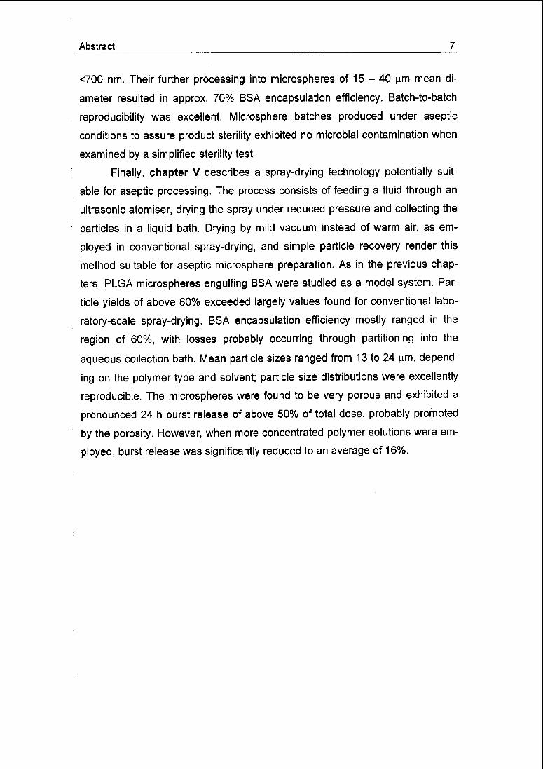
Finally, chapter V describes a spray-drying technology potentially suit¬
able for aseptic processing. The process consists of feeding a fluid through an
ultrasonic atomiser, drying the spray under reduced pressure and collecting the
particles in a liquid bath. Drying by mild vacuum instead of warm air, as em¬
ployed in conventional spray-drying, and simple particle recovery render this
method suitable for aseptic microsphere preparation. As in the previous chap¬
ters, PLGA microspheres engulfing BSA were studied as a model system. Par¬
ticle yields of above 80% exceeded largely values found for conventional labo¬
ratory-scale spray-drying. BSA encapsulation efficiency mostly ranged in the
region of 60%, with losses probably occurring through partitioning into the
aqueous collection bath. Mean particle sizes ranged from 13 to 24 u.m, depend¬
ing on the polymer type and solvent; particle size distributions were excellently
reproducible. The microspheres were found to be very porous and exhibited a
pronounced 24 h burst release of above 50% of total dose, probably promoted
by the porosity. However, when more concentrated polymer solutions were em¬
ployed, burst release was significantly reduced to an average of 16%.

8 Abstract
Seite Leer /
Blank leaf

Zusammenfassung 9
Zusammenfassung
Die pilot- und grosstechnische Produktion von Mikrosphären aus Po-
ly(milch-co-glykolsäure) (PLGA) als parenteral verabreichtes System zur kon¬
trollierten Wirkstoffabgabe hat zwei Hürden zu überwinden: Einerseits die Not¬
wendigkeit, ein steriles partikuläres Produkt zu erzeugen und andererseits die
Aufstufung relativ komplexer Prozesse. Da PLGA hitzeempfindlich reagiert
(Tg « 40°C), ist eine Sterilisation des Endprodukts über Hitze oder Dampf nicht
möglich. Der Einsatz von y-Strahlen zur Sterilisation kann zu einer Spaltung der
Polymerketten und damit zu einem negativ veränderten Freisetzungsverhalten
des Wirkstoffs aus den Mikrosphären führen. Aus diesen Gründen ist die asep¬
tische Produktion der Mikrosphären zu präferieren. Im Rahmen dieser Arbeit
sollten Verfahren zur Emulgierung und zur Produktion von Mikrosphären entwi¬
ckelt werden, die für eine aseptische Prozessführung besonders gut geeignet
sind und sich einfach aufstufen lassen. Die entwickelten Verfahren wurden an¬
hand der Verkapselung von bovinem Serumalbumin (BSA) als Modellprotein in
PLGA-Mikrosphären charakterisiert und der Einfluss verschiedener Prozess-
und Formulierungsparameter wurde untersucht.
Kapitel I gibt einen Überblick über den aktuellen Stand der Technik bei
Verfahren zur Mikroverkapselung mittels LösungsmittelextraktionAevaporation,
die am häufigsten angewendete Methode zur Mikroverkapselung. Erste Labor¬
versuche mit dieser Methode werden gewöhnlich in einem einfachen Rührge-
fäss durchgeführt. Dieses Verfahren ist jedoch ungeeignet, um grössere Men¬
gen an Mikrosphären in einer für klinische Studien oder eine Vermarktung aus¬
reichenden Qualität zu produzieren. Hier sind wirtschaftliche, robuste und ver¬
lässlich steuerbare Prozesse erforderlich. Die Mikroverkapselung mittels LÖ-
sungsmittelextraktion/-evaporation lässt sich in vier Teilprozesse unterteilen:
(1) Einarbeiten der Wirksubstanz, (2) Bilden der Mikrotropfen, (3) Entfernen des
Lösungsmittels und (4) Separieren und Trocknen der ausgehärteten Mikrosphä¬
ren. Mikrotropfen können durch Rühren, statisches Mischen, Extrusion via
Hohlnadeln, Mikrokanalsysteme oder Membranen, sowie durch Zertropfung
mittels elektrostatischer Kräfte oder Ultraschallanregung eines Flüssigkeits¬
strahls erzeugt werden. Das Lösungsmittel, in dem das Matrixmaterial zusam¬
men mit der Wirksubstanz gelöst ist, kann durch Verdampfung - gegebenen-
10 Zusammenfassung
falls unterstützt durch Wärmezufuhr oder Unterdruck - oder per Extraktion mit¬
tels wässriger oder organischer Lösungen aus den zuvor gebildeten Mikrotrop¬
fen entfernt werden.
Der erste Verfahrensschritt bei der Herstellung wirkstoffbeladener Mikro¬
sphären besteht gewöhnlich in der Dispergierung der Wirksubstanz in einer Lö¬
sung des matrixbildenden Materials. Bei der Verkapselung von Proteinen wird
diese Dispersion häufig durch Emulgierung einer wässrigen Protein- in einer
organischen Matrixlösung mittels Ultraschall erhalten. Dabei wird häufig eine
Ultraschallsonde in ein kleines, die beiden Lösungen enthaltendes Gefäss ge¬
taucht und aktiviert. Eine Alternative zu diesem Vorgehen wird in Kapitel II vor¬
gestellt. Die dort beschriebene Durchfluss-Ultraschallzelle besteht aus einem
Glassrohr, das mittig in einem Stahlmantel installiert ist, welcher von einer So-
notrode in Ultraschallschwingungen versetzt wird. Eine Übertragung der
Schallwellen erfolgt durch unter Druck gesetztes Wasser, das den Zwischen¬
raum zwischen Glassrohr und Stahlmantel durchströmt. Durch dieses Verfahren
wird eine Kontamination des beschallten Gutes mit Metallpartikeln, welche von
der Sonotrode erodiert werden könnten, verhindert. Durch die kontinuierliche
Verfahrensweise und die vollständige Abtrennung des beschallten Gutes von
der Umgebung wird eine mikrobielle Kontamination verhindert. Die Ultraschall-
Durchflusszelle wurde anhand der Emulgierung von pflanzlichen Ölen in Was¬
ser - einem Standardsystem zur Charakterisierung von Emulgierverfahren - un¬
tersucht. Dabei wurden Öl und Wasser der Ultraschallzelle als grobe Voremul¬
sion zugeführt. Während der Passage durch die Zelle wurde die Emulsionstrop-
fengrösse um zwei Grössenordnungen verringert, so dass am Ausgang Emulsi¬
onen mit einem Sauter-Durchmesser von 0,5 jum erhalten wurden. Die Ergeb¬
nisse waren dabei hervorragend reproduzierbar. Eine Erhöhung der Schallleis¬
tung und eine Verlängerung der Verweilzeit im Schallfeld resultierten in kleine¬
ren, eine disperse Phase höherer Viskosität und eine erhöhte Grenzflächen¬
spannung in grösseren Emulsionströpfchen. Die Effizienz der Energieübertra¬
gung betrug nur rund 10%, was dem verhältnismässig komplexen Übertra¬
gungsmechanismus zugeschrieben wurde.
Kapitel III beschreibt die Verwendung eines statischen Mikromischers
zur Verkapselung von BSA in PLGA-Mikrosphären mittels Lösungsmittelextrak-

Zusammenfassung 11
tion. Die Tröpfchenbildung innerhalb des Mischers findet in einem gitterförmigen
System aus Mikrokanälen statt. Seine simple Konstruktion, geringe Grösse,
einfache Handhabung sowie seine Eignung zu kontinuierlicher Produktion las¬
sen den Mikromischer ideal für eine aseptische Produktion von Mikrosphären
erscheinen. Eine Aufstufung des Prozesses ist sehr einfach durch Parallelschal¬
ten hinreichend vieler Mischer möglich („number-up"). Der mittlere Durchmesser
der erzeugten Mikrosphären konnte durch einfache Variation der Flussraten, mit
denen die Flüssigkeiten den Mischer passieren, in einem Bereich von 9 bis 30
um eingestellt werden. Die Partikelgrössenverteilung der Mikrosphären war
problemlos reproduzierbar und weitgehend unbeeinflusst von der Konzentration
der Polymerlösung, dem Typ des Polymers, sowie der Beladung mit BSA. Im
Gegensatz dazu zeigte das zum Lösen des Polymers verwendete Lösungsmit¬
tel deutlichen Einfluss auf die Partikelgrösse der erzeugten Mikrosphären. Die
Effizienz der BSA-Verkapselung lag generell im Bereich von 75 - 85%.
Kapitel IV beschreibt die Kombination von Ultraschall-Durchflusszelle
und statischem Mikromischer zur Produktion von BSA-beladenen Mikrosphä¬
ren. Die Ultraschallzelle erzeugt dabei in einem ersten Schritt eine Emulsion
aus einer BSA- und einer PLGA-Lösung. Diese wird nachfolgend im Mikromi¬
scher zu im Extraktionsmedium dispergierten Mikrosphären weiterverarbeitet.
Die mittlere Tröpfcheng rosse der mittels Ultraschallzelle produzierten
BSA/PLGA-Emulsionen lag stets unterhalb 700 nm. Die daraus erzeugten Mik¬
rosphären wiesen einen mittleren Durchmesser von 15 - 40 u.m und eine Ver-
kapselungseffizienz von ca. 70% des eingesetzten BSAs auf. Die Reproduzier¬
barkeit der Versuchsergebnisse war gut. Unter aseptischen Bedingungen mit
diesem Verfahren hergestellte Mikrosphären wiesen in einem vereinfachten
Sterilitätstest keinerlei mikrobielle Kontamination auf.
Im Kapitel V wird schliesslich ein Sprühtrocknungsverfahren beschrie¬
ben, welches für eine aseptische Produktion von Mikrosphären gut geeignet
erscheint. Eine die Wirksubstanz und Polymer enthaltende Lösung wird dabei
mittels Ultraschallsprühkopf in einen unter verringertem Druck stehenden Glas¬
behälter zerstäubt und dabei getrocknet. Die entstehenden Partikel sedimentie-
ren in ein Auffangbad, mit dem sie aus dem Behälter entnommen werden kön¬
nen. Die Verwendung von Unterdruck anstelle warmer Luft, wie in herkömmli-
12 Zusammenfassung
cher Sprühtrocknung verwendet, und die einfache Gewinnung der in der Auf¬
fanglösung dispergierten Partikel vereinfachen eine aseptische Verfahrenswei¬
se ganz erheblich. Wie schon in den vorhergehenden Kapiteln wurde das Ver¬
fahren anhand der Verkapselung von BSA in PLGA-Mikrosphären charakteri¬
siert. Produktausbeuten von über 80% übersteigen die in konventionellen La¬
borsprühtrocknern erzielten bei weitem. Die Effizienz der BSA-Einkapselung lag
mit rund 60% eher niedrig. Die Ursache liegt vermutlich in der Diffusion von
BSA aus den dispergierten Mikrosphären in das wässrige Auffangbad. Je nach
verwendetem Polymertyp und -lösungsmittel lag die mittlere Partikelgrösse
zwischen 13 und 24 (im. Die Partikelgrössenverteilung Hess sich gut reproduzie¬
ren. Die Mikrosphären waren sehr porös und zeigten vermutlich deshalb eine
ausgeprägte Startfreisetzung von über 50% der Gesamtdosis innerhalb der ers¬
ten 24h. Mit der Verwendung einer konzentrierteren Polymerlösung konnte die
anfängliche Freisetzung jedoch deutlich auf ca. 16% reduziert werden.

Chapter I 13
Chapter I
Microencapsulation by solvent extraction/evaporation: reviewing the state
of the art of microsphere preparation process technology
Sergio Freitas, Hans P. Merkte, and Bruno Gander
Department of Chemistry and Applied Biosciences, Institute of Pharmaceutical Sci¬
ences, Swiss Federal Institute of Technology Zürich, ETH Hönggerberg HCl,
8093 Zürich, Switzerland
Journal of Controlled Release, 102 (2005) 313-332

14 Chapter I
1.1 Introduction
Biodegradable microspheres are widely investigated delivery systems for
bioactive compounds such as low molecular weight and macromolecular thera¬
peutics, antigens or DNA. As such they may add substantially to the value of
therapies and vaccinations. Considered for parenteral, pulmonary, oral or nasal
administration, they are capable of providing sustained and controlled release of
the encapsulated bioactive compound, while the non-released bioactive mate¬
rial may be protected from degradation and physiological clearance. For vac¬
cines, microspheres may provide additional adjuvancy [1,2] and allow for direct
targeting to professional antigen presenting cells [3], Furthermore, they may be
surface-modified to target specific cells [4] and tissues [5].
Owing to their excellent biocompatibility, the biodegradable polyesters
poly(lactic acid), PLA, and poly(lactic-co-glycolic acid), PLGA, are the most fre¬
quently used biomaterials for the microencapsulation of therapeutics and anti¬
gens [6,7]. Other materials like proteins [5], polymer blends [8], polysaccharides
such as chitosan [9], and lipids [10] have also been studied, though at a lower
frequency. A large variety of bioactive compounds have been formulated into
microspheres, among them antineoplastic drugs [11,12], narcotics [13], anaes¬
thetic agents [14] as well as therapeutic peptides [15,16] and proteins [17,18],
DNA [19,20], viruses [21] and bacteria-derived compounds [22,23]. Preparation
technologies capable of producing larger amounts of microspheres in a safe,
economic, robust and well-controlled manner are therefore required.
In accordance with the common practice in literature, in this paper, the terms "micro¬
spheres" and "microparticles" are used interchangeably. The same holds true for the
terms "encapsulation" and "entrapment".
Abbreviations: ACN: acetonitrile; BSA: bovine serum albumin; CSTR: continuouslystirred tank reactor; CV: coefficient of variation; DCM: dichloromethane; HPMC: hy-
droxypropylmethylcellulose; OVA: ovalbumin; PEG: poly(ethylene glycol); PLA:
poly(lactic acid); PLGA: poly(lactic-co-glycolic acid); PMMA: poly(methyl methacrylate);
PTFE; poly(tetrafluorethylene); PVA: polyvinyl alcohol); PVP: polyvinyl pyrrolidone);rhGH: recombinant human growth hormone; sCT: salmon calcitonin; SDS: sodium do-
decyl sulfate; SPG: Shirasu Porous Glass.

Chapter I 15
Microspheres have been prepared by various techniques, which feature
partly competing, partly complementary characteristics. Many microencapsula¬
tion processes are modifications of the three basic techniques solvent extrac¬
tion/evaporation, phase separation (coacervation) and spray-drying [24]. Spray-
drying is relatively simple and of high throughput, but must not be used for
highly temperature-sensitive compounds. Moreover, control of the particle size
is difficult, and yields for small batches are moderate [25]. Coacervation is fre¬
quently impaired by residual solvents and coacervating agents found in the mi¬
crospheres [26]. Furthermore, it is not well suited for producing microspheres in
the low micrometer size range. The use of supercritical gases as phase sepa¬
rating agents was intensively studied to minimize the amount of potentially
harmful residues in the microspheres, resulting in processes named, e.g., Pre¬
cipitation with Compressed Antisolvent (PCA) [27], Gas or Supercritical fluid
Anti-Solvent (GAS or SAS), and Aerosol Solvent Extraction System (ASES)
[28]. Solvent extraction/evaporation neither requires elevated temperatures, nor
phase separation inducing agents. Controlled particle sizes in the nano- to mi¬
crometer range can be achieved, but careful selection of encapsulation condi¬
tions and materials is needed to yield high encapsulation efficiencies and a low
residual solvent content.
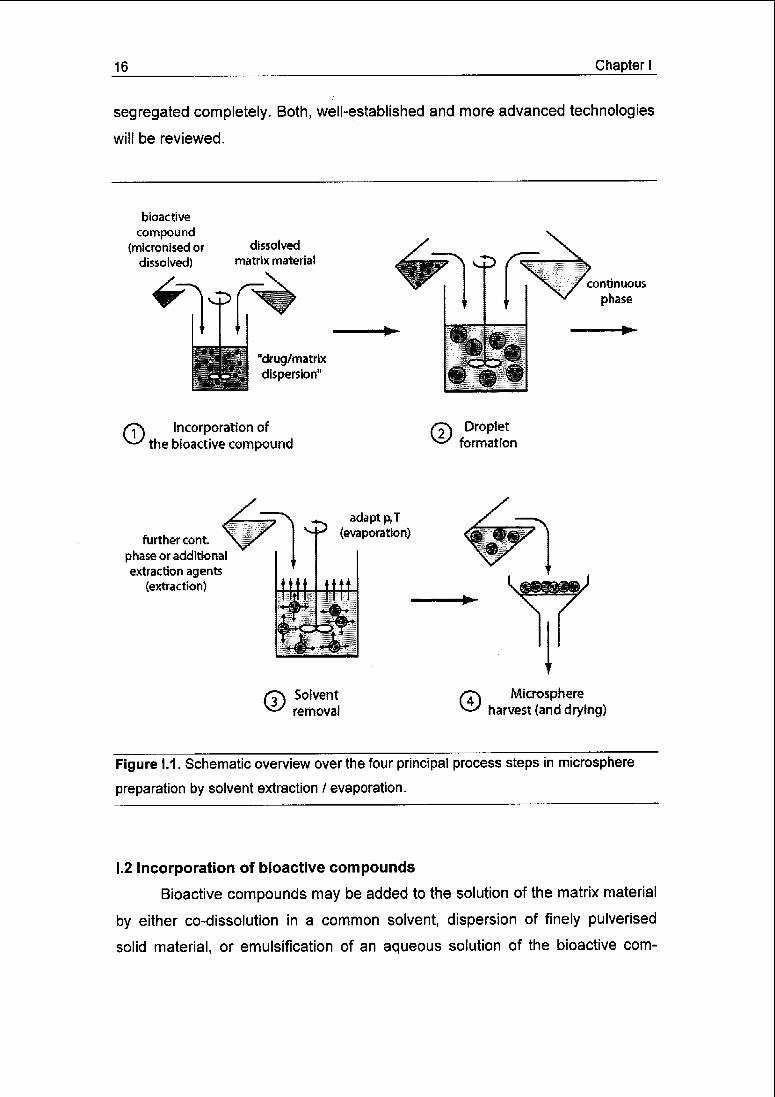
Microsphere preparation by solvent extraction/evaporation basically con¬
sists of four major steps: (i) dissolution or dispersion of the bioactive compound
often in an organic solvent containing the matrix forming material; (ii) emulsifica¬
tion of this organic phase in a second, continuous (frequently aqueous) phase
immiscible with the first one; (iii) extraction of the solvent from the dispersed
phase by the continuous phase, which is optionally accompanied by solvent
evaporation, either one transforming the droplets into solid microspheres;
(iv) harvesting and drying of the microspheres (Fig. 1.1).
This article reviews the current state of the art in solvent extrac¬
tion/evaporation based microencapsulation technology with a focus on process-
related aspects. Issues like materials, microsphere formulation, choice of ap¬
propriate solvents or surfactants are not central aspects of this review, though
technology and starting materials are interconnected and can by no means be
16 Chapter I
segregated completely. Both, well-established and more advanced technologies
will be reviewed.
bioactive
compound(micronised or
dissolved)
dissolved
matrix material
"drug/matrix
dispersion" wwß'J'*'"'"'
continuous
phase
/"f\ Incorporation of^ the bioactive compound
/J\ Dropletformation
further cont.
phase or additional
extraction agents
(extraction)
^ adapt p,TM-' (evaporation)
/Ts Solvent^ removal
© Microsphereharvest (and drying)
Figure 1.1. Schematic overview over the four principal process steps in microsphere
preparation by solvent extraction / evaporation.
I.2 Incorporation of bioactive compounds
Bioactive compounds may be added to the solution of the matrix material
by either co-dissolution in a common solvent, dispersion of finely pulverised
solid material, or emulsification of an aqueous solution of the bioactive com-
Chapter I 17
pound immiscible with the matrix material solution [29]. Co-dissolution may re¬
quire a co-solvent to fully dissolve the drug in the matrix containing solvent.
Dispersion of the solid or dissolved bioactive material in the matrix containing
solution may be achieved by ultrasonication [30], impeller or static mixing [31],
high-speed rotor-stator mixing [32], or microfluidisation [30].
The microencapsulation of hydrophilic compounds by dispersion of their
aqueous solution in an organic solution of the matrix material was more efficient
with finer W/O-emulsions, i.e. at a lower ratio of bioactive material droplet size
to microsphere diameter [32,33]. For the entrapment of bovine serum albumin
(BSA) into poly(methyl methacrylate) (PMMA) microspheres, a ratio of less than
1:10 was suggested to yield protein loadings of >80% [32]. A higher target load
of bioactive material is likely to decrease the encapsulation efficiencies of pro¬
teins and peptides in PLGA [33,34,35] and increase the 24 h ("burst") drug re¬
lease [35,36], although some studies report the opposite, e.g., an increase in
entrapment efficiency of ovalbumin (OVA) from 40 to 98% with an increase in
actual OVA content from 7 to 16% (w/w) [37,38]. Increasing the volume fraction
of the internal aqueous phase lowered the encapsulation efficiency due to drop¬
let coalescence and increased probability of contact between the internal drug
solution and the external extraction phase resulting in drug loss [39,40]; in addi¬
tion, an increase in the burst release and microsphere porosity was reported
[41,42].
In analogy, entrapment of solid protein particles also improved with de¬
creasing particle size [32,43]. The particle size of drug powders can be reduced
by either micronisation of the drug powder prior to its dispersion, or during the
dispersion step itself [44,45], or by the use of excipients which are co-
formulated with the drug so that the blended material dissolves in the matrix's
solvent [46]. Finally, spherically shaped protein particles caused a trend towards
more efficient encapsulation than irregular ones [32].
For efficient encapsulation of drugs dissolved in an aqueous phase to be
dispersed in an organic matrix solution, stabilisation of the resulting W/O-
emulsion may be required. When drug-free microparticles were prepared from
emulsions consisting of plain water and PLA dissolved in dichloromethane
(DCM) [47], increasing amounts of BSA added to the water as a surfactant sta-
18 Chapter I
bilised the emulsions and decreased the pore sizes in the resulting micro¬
spheres; the latter observation was ascribed to the finer water droplets that
were entrapped and left a corresponding void in the matrix. The addition of a
surfactant (poloxamer) to the organic phase was found to be much less effi¬
cient. Similarly, the model substance indigocarmine was more efficiently en¬
trapped with increasing BSA concentrations in the inner water phase [48]. Other
substances, e.g., gelatine [49], polyvinyl alcohol) (PVA) [35], ovalbumin [50] or
combinations of sorbitan esters and polysorbates [51] have also been reported
for the stabilisation of such W/O-emulsions. The selection of stabilisers for the
W/O-emulsion has to be made with caution, as co-encapsulated surfactants can
adversely affect drug encapsulation efficiency and release [48,52].
I.3 Droplet formation
The droplet formation step determines the size and size distribution of
the resulting microspheres. Microsphere size may affect the rate of drug re¬
lease, drug encapsulation efficiency, product syringeability, in vivo fate in terms
of uptake by phagocytic cells and biodistribution of the particles after subcuta¬
neous injection of intranasal administration. In the following, the main proce¬
dures used for droplet formation in microsphere production are described.
Henceforth, the different types of mixtures of bioactive and matrix materials de¬
scribed above will, for simplicity, be referred to as drug/matrix dispersion.
1,3,1 Stirring
Stirring is the most straightforward method to generate droplets of the
drug/matrix dispersion in the continuous extraction phase for subsequent sol¬
vent removal. In the simplest approach, extraction phase is filled into a vessel
and agitated by an impeller. The drug/matrix dispersion is then added, drop-
wise or all at once, under agitation at a speed sufficient to reach the desired
droplet size.
Obviously, the impeller speed is the main parameter for controlling the
drug/matrix dispersion's droplet size in the continuous phase. Increasing the
mixing speed generally results in decreased microsphere mean size

Chapter I 19
[35,53,54,55], as it produces smaller emulsion droplets through stronger shear
forces and increased turbulence. The extent of size reduction that is attained
depends on the viscosity of the disperse and continuous phases, the interfacial
tension between the two phases, their volume ratio, the geometry and number
of the impeller(s), and the size ratio of impeller and mixing vessel. For example,
a 52 mm impeller installed in a 250 ml beaker of 65 mm inner diameter pro¬
duced microsphere mean diameters decreasing from 38 to 14 urn with impeller
speed increasing segmentially from 250 to 1600 rpm, using PLGA dissolved in
DCM and an aqueous HPMC solution as disperse and continuous phases, re¬
spectively [53]. In addition to a smaller mean diameter, more vigorous mixing
also resulted in lower microsphere polydispersity [53,56].
Increased viscosity of the drug/matrix dispersion yields larger micro¬
spheres because higher shear forces are necessary for droplet disruption
[16,33,38,41,57]. For PLGA dissolved at 6.25, 12.5 and 25% in a mixture of
acetonitrile (ACN) and DCM and dispersed in liquid paraffin, microsphere mean
diameters of 36, 115 and 208 jam were obtained [57]. Such increase in
drug/matrix dispersion viscosity, typically caused by higher concentration or mo¬
lecular weight of the matrix material, may be desirable to restrict the migration
of the drug to the continuous phase and thus improve its entrapment.
To prevent coalescence of the drug/matrix dispersion droplets, a surface-
active or viscosity enhancing stabiliser such as PVA is generally added to the
continuous phase. Increasing the stabiliser concentration frequently leads to
decreased microsphere sizes [20,35,37,53,58]. For instance, when micro¬
spheres were prepared from PLGA dissolved in DCM and emulsified in an
aqueous PVA solution, the mean diameter decreased from 8.3 to 3.7 |am when
the PVA concentration was increased step-wise from 1 to 10% [37]. When
HPMC was used as a stabiliser, an increase of its concentration in the continu¬
ous phase from 0.4 to 2.4% resulted in an almost linear decrease of the micro¬
sphere size from 29 to 13 urn along with a reduced width of the size distribution
[53]. Higher stabiliser concentrations will yield a larger excess of material that
adsorbs on the surface of newly formed droplets, thus preventing coalescence
[35,53]. With macromolecular stabilisers, the viscosity of the continuous phase
20 Chapter I
will also increase, amplifying - for a given stirring rate - the shear forces acting
upon the drug/matrix dispersion droplets and, thus, minimising their size.
Reports about the impact of the volume ratio between drug/matrix dis¬
persion and continuous phase on the size of the resulting microspheres are
conflicting. Various studies reported a reduction in the mean microsphere size
with decreasing continuous phase volume [16,37,59,60], while in other studies
no significant effect was observed [53,54].
In an attempt to predict the mean diameter of microspheres prepared in a
so-called continuously stirred tank reactor (CSTR), an empirical equation was
derived [61]. In a vast number of experiments, the size of PLGA and PMMA par¬
ticles was correlated with reactor parameters and fluid properties using dimen¬
sional analysis. In agreement with previous reports, the equation predicted a
strong correlation of the microsphere mean diameter with stirring speed, impel¬
ler diameter (decreased diameter) and polymer concentration (increased diame¬
ter), as well as moderate correlation with continuous phase viscosity (decreased
diameter) and interfacial tension (increased diameter). Disperse and continuous
phase volumes did not significantly influence microsphere size. The equation
reproduced and predicted the microsphere diameter with good accuracy for dif¬
ferent types of extraction fluids and for microspheres without and with protein
loading. Also, in scaled-up equipment (from 1 to 3, 10 and 100 liters), the devia¬
tion of the predicted diameter from the experimentally obtained one was less
than 20%. However, no prediction on the width of the particle size distribution
could be made.
1.3.2 Static mixing
Static mixers consist of baffles or other flow obstacles installed in a tube.
The baffle arrangement repeatedly splits and recombines the stream of fluid
passing through the tube. Recombination occurs through impingement of the
substreams, creating turbulence and inducing back-mixing.
In a comprehensive study, static mixers of different baffle design, length
(4 - 76 cm) and diameter (0.6 - 2.5 cm) were examined for microsphere produc¬
tion involving concentrated solutions (18 and 30%, w/w) of PLGA and PMMA in
DCM dispersed in aqueous PVA solutions [62], Using continuous phase flow

Chapter I 21
rates of 36 to 320 l/h yielded microsphere mean diameters of 35 to 90 urn. For
each of the three mixer designs, an empirical equation relating microsphere size
to fluid properties, mixer geometry and flow rate was derived by dimensional
analysis. Correlation between the equations and experimental data was good,
as was the predictive power, with the calculated mean diameter deviating less
than 10% from that experimentally determined. Analysis of the equations re¬
vealed that increasing the interfacial tension, polymer concentration and mixer
diameter produced larger microspheres, while increasing the flow rate, continu¬
ous phase viscosity and length of the mixer resulted in smaller particles. More¬
over, the authors concluded that the mean size of the microspheres would not
change during scale-up if the flow velocity inside the mixer could be maintained.
However, no statement about retention of the particle size distribution was
made, which is of equal interest in a scale-up. For the three mixer designs stud¬
ied, a ranking with respect to emulsification efficiency was established and ex¬
plained with respect to baffle geometry. A comparison of the static mixers with a
CSTR for emulsification efficiency revealed that static mixers generate the
same degree of mixing at much lower Reynold numbers. Uniformity of the parti¬
cle size distribution was not improved by static mixing. The authors concluded
that static mixing scores over CSTR-based microencapsulation with respect to
process continuity, mixing efficiency and scalability.
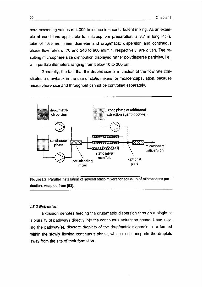
A convenient way to scale-up microencapsulation by static mixing is the
parallel installation of several small-diameter mixers with outflows that are re-
combined downstream, rather than using a single mixer of larger diameter
(Fig. 1.2) [63]. A pre-blending mixer preceding the mixer manifold ensures that a
uniformly composed pre-emulsion of drug/matrix dispersion and extraction
phase enters each mixer of the manifold. Furthermore, it was observed that the
uniformity and symmetry of the microspheres' size distribution was improved by
increasing the emulsion's residence time in the static mixer manifold, i.e. by in¬
creasing the manifold's length.
As an alternative to classical static mixing, a tube of very small diameter
was suggested for the formation of an emulsion of the drug/matrix dispersion in
the continuous extraction phase [64]. The two phases to be mixed were
pumped through such a tube at flow rates high enough to yield Reynolds num-
22 Chapter I
bers exceeding values of 4,000 to induce intense turbulent mixing. As an exam¬
ple of conditions applicable for microsphere preparation, a 3.7 m long PTFE
tube of 1.65 mm inner diameter and drug/matrix dispersion and continuous
phase flow rates of 70 and 240 to 900 ml/min, respectively, are given. The re¬
sulting microsphere size distribution displayed rather polydisperse particles, i.e.,
with particle diameters ranging from below 10 to 200 urn.
Generally, the fact that the droplet size is a function of the flow rate con¬
stitutes a drawback in the use of static mixers for microencapsulation, because
microsphere size and throughput cannot be controlled separately.
drug/matrixdispersion
continuous
phaseK7VVL
<2H
cont. phase or additional
extraction agent (optional)
,i
EX2-
static mixer
manifold
pre-blendingmixer
microsphere
suspension
optional
port
Figure 1.2. Parallel installation of several static mixers for scale-up of microsphere pro¬
duction. Adapted from [63].
1.3.3 Extrusion
Extrusion denotes feeding the drug/matrix dispersion through a single or
a plurality of pathways directly into the continuous extraction phase. Upon leav¬
ing the pathway(s), discrete droplets of the drug/matrix dispersion are formed
within the slowly flowing continuous phase, which also transports the droplets
away from the site of their formation.
Chapter I 23
Extrusion is distinguished from static mixing by the droplet forming
mechanism and the prevailing flow regime. In extrusion, the flow is mainly lami¬
nar and the droplets are formed directly at the site of introduction of the dis¬
persed phase into the continuous phase and do not change their dimension
thereafter (given that coalescence is negligible). On the contrary, static mixing
relies mainly on turbulent flow, which constantly acts on the disperse phase
and, thus, causes the size of the droplets to change over the whole length of the
mixer. Therefore, extrusion is considered to allow for more uniform and better
controlled microsphere sizes than static mixing.
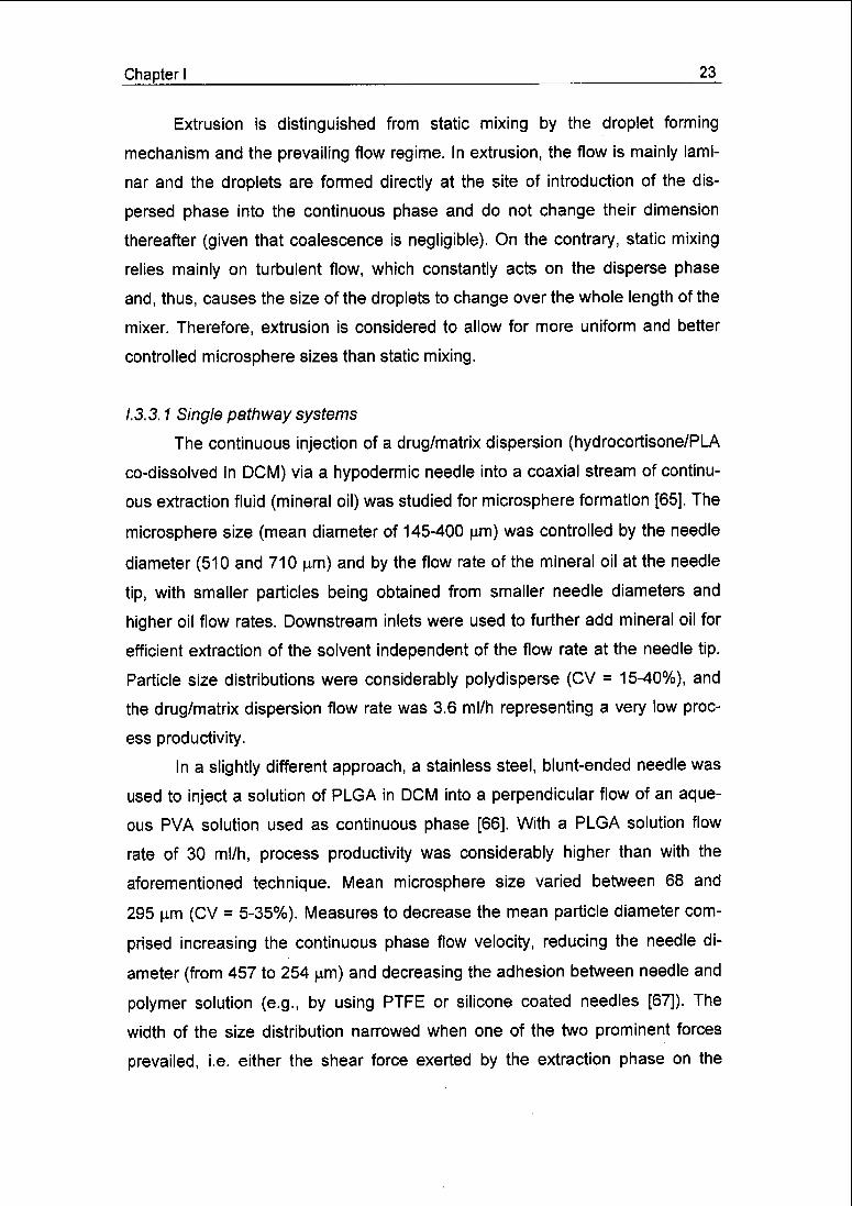
1.3.3.1 Single pathway systems
The continuous injection of a drug/matrix dispersion (hydrocortisone/PLA
co-dissolved in DCM) via a hypodermic needle into a coaxial stream of continu¬
ous extraction fluid (mineral oil) was studied for microsphere formation [65]. The
microsphere size (mean diameter of 145-400 urn) was controlled by the needle
diameter (510 and 710 |im) and by the flow rate of the mineral oil at the needle
tip, with smaller particles being obtained from smaller needle diameters and
higher oil flow rates. Downstream inlets were used to further add mineral oil for
efficient extraction of the solvent independent of the flow rate at the needle tip.
Particle size distributions were considerably polydisperse (CV = 15-40%), and
the drug/matrix dispersion flow rate was 3.6 ml/h representing a very low proc¬
ess productivity.
In a slightly different approach, a stainless steel, blunt-ended needle was
used to inject a solution of PLGA in DCM into a perpendicular flow of an aque¬
ous PVA solution used as continuous phase [66]. With a PLGA solution flow
rate of 30 ml/h, process productivity was considerably higher than with the
aforementioned technique. Mean microsphere size varied between 68 and
295 u.m (CV = 5-35%). Measures to decrease the mean particle diameter com¬
prised increasing the continuous phase flow velocity, reducing the needle di¬
ameter (from 457 to 254 |am) and decreasing the adhesion between needle and
polymer solution (e.g., by using PTFE or silicone coated needles [67]). The
width of the size distribution narrowed when one of the two prominent forces
prevailed, i.e. either the shear force exerted by the extraction phase on the

24 Chapter I
growing droplet, or the adhesion force between the droplet and the needle tip.
Changing the angle between needle and extraction phase flow from 90 to 45°
did not significantly influence the microsphere size distribution [67].
Generally, the single pathway extrusion systems have turned out to be
unsuitable for the production of small microspheres (<50 urn), and their
throughput was quite low. Scale-up may be feasible through parallel employ¬
ment of a plurality of needles, which, however, might be difficult to implement
without considerably perturbing the flow of the extraction phase and causing in¬
teractions between the outflows from the different needles.
Figure 1.3 a-d. Multilamination micromixer, (a) Assembled micromixer, (b) Dismantled
mixer with extracted mixing tool, (c) Close-up of the microchannel array. Channel width
is 40 urn. (d) Formation and disintegration of fluid lamellae in the mixer's outlet slit, (a)-
(c) with kind permission of Institut für Mikrotechnik Mainz (www.imm-mainz.de); (d) re¬
produced from [68] with permission.

Chapter I 25
eZM
tmm,
C
o+J Ao / \ro / \
m- /\ / A I
0) / a\ / A I
| 10 //W/\ lo / / V\ / \ I> // IV \ Ire / / Aa \ \+j / / / V \ \ \c / / / A \ \ \d) / / I \\ \ \^
a) I! / / \ \ \\t // / / \\ \ \a J/// \\\v
0^'
_
_^" ^ . / \ ^-?p^—' ' ' ' ' ' ' ' ' ' ' '
0.1 1 10 100
Microsphere diameter [u,m]
Figure I.3 e. Multilamination micromixer, (e) Control of the microsphere size by varia¬
tion of the flow rates. Extraction phase flow rate was 1200, 900, 600 and 420 ml/h (size
distributions from left to right); drug/matrix dispersion flow rate was adapted at 1/50 of
the extraction fluid rate. Reproduced from [68] with permission.
1.3.3.2 Multichannel systems
Recently, a micromixer consisting in essence of an array of fine channels
(25 or 40 urn in width; 300 urn in depth; Fig. 1.3 a-c) was employed for micro¬
sphere preparation [68]. PLGA dissolved in DCM, into which an aqueous BSA
solution was emulsified, and an aqueous PVA solution used as extraction phase
were separately fed into the microchannel array from opposite sides and dis¬
charged through an outlet slit (60 p.m wide), which was micromachined in the
mixer housing's top plate perpendicular and central to the channel array
(Fig. 1.3 b). Upon entering the outlet slit, alternating fluid lamellae of the two fluid
phases formed. Owing to the much faster flow rate of the extraction fluid, the
microsphere forming phase disintegrated into droplets (Fig. 1.3 d) [68,69], The

26 Chapter
mean microsphere diameter was tuned from 8 to 29 urn by simply varying the
flow rates of the two fluids pumped through the mixer (Fig. 1.3 e). Relatively
wide particle size distributions were obtained, e.g., ranging from 4 to 60 urn for
a mean diameter of 16 urn. Interestingly, both the microsphere mean size and
size distribution remained largely unaffected by varying PLGA solution concen¬
trations (2 - 10%, w/w), drug load and polymer type. On the contrary, switching
the polymer solvent from DCM to ethyl formate yielded considerably smaller mi¬
crospheres (7 urn mean diameter instead of 16 urn for DCM), which was attrib¬
uted to decreased interfacial tension. Scale-up can be comfortably achieved by
so-called numbering-up, i.e., by employing a large number of micromixers in
parallel. Owing to its simple design and because it may be easily sterilised, the
micromixer was suggested for aseptic microsphere manufacturing [68].
continuous
disperse phase phase
(drug/matrix
dispersion)
glassplate
microchannels
(see detail "b")
q*q^^* il" i v ^^m^j^^yn o
o rru
o o
0°o o
further processingfor solvent removal
Figure 1.4 a. Interfacial tension driven droplet formation using a microchannel device,
(a) Experimental set-up. Adapted from [76].

Chapter I 27
Channel./ Teirace
Wei!
'vEnmulsif«c3tion point
Glass plate Inflation
piocess
Detachment
process
Figure 1.4 b,c. Interfacial tension driven droplet formation using a microchannel device,
(b) Detailed view of the spot of droplet formation exemplified for an oil-in-water mono-
disperse emulsion (c) Formation of a droplet from a microchannel. (b) and (c) repro¬
duced from [76] and [74], respectively Reproductions with permission
Another simple and ingenious microchannel system, etched into a silicon
chip (Fig. 1.4 a,b) [70], was examined intensively for the formation of monodis¬
perse emulsions and, more recently, for the solvent evaporation-based prepara¬
tion of uniform lipid microparticles [71]. The channels measure only a few mi¬
crometers in height and width and open up to a terrace that descends to a well
through which the continuous phase slowly passes (Fig. 1.4 b,c). The device is
covered by a glass plate to allow for observation by a camera system. The dis¬
perse phase, flowing out of the microchannel, spreads into the space between
the terrace and the glass cover in a disk-like shape until it reaches the rim of the
well. When flowing over the rim and into the well, interfacial forces contract the
fluid to form a droplet (Fig. 1.4 c). The interfacial area of the disperse phase as
28 Chapter I
1.0
>.
a> 0.5
CTco
IL
(a) 6-4-0
1.4x10⁻²
T
ml,' min'1
j
°ave
°9
= 16.2
= 1.03 -
• »
1.0
o
m 0.5
<DLu¬
ll
(d) 6-4-0
2.4 mL-min'1
I
dave = 16.2
Og = 1.02
i i —
1.0
o
fe 0.5
cr
0 10 20 30 40 50
Droplet size [urn]
(b) 6-4-50
1.4 x10"2 mL-min*1
Og = 1.03
1.0
10 20 30 40 50
Droplet size [urn]
i
<_>
c
<» 0.5
©
(e) 6-4-5C
i
2.4 mL*mirf
Og =1.01
1 i—
10 20 30 40 50
Droplet size [urn]
10 20 30 40 50
Droplet size fjim]1.0
o
o 0.53CJ"<DL.
(C) 6-12-0
1.4 x10"2 mL-min"1
daVe = 47.6
®a = 1-02
III
1.0
o
ca> 0.5
œ
(0 6-12-0
2.4 mL-min-1
Jave
= 1.01
0 10 20 30 40 50
Droplet size [urn]
10 20 30 40 50
Droplet size [urn]
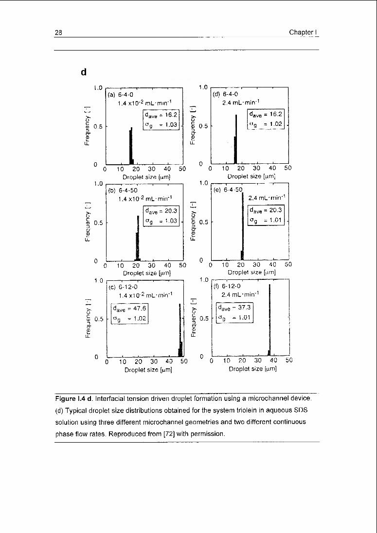
Figure 1.4 d. Interfacial tension driven droplet formation using a microchannel device,
(d) Typical droplet size distributions obtained for the system triolein in aqueous SDS
solution using three different microchannel geometries and two different continuous
phase flow rates. Reproduced from [72] with permission.

Chapter I 29
spread on the terrace is large compared to that of the droplet in the well, driving
the fluid to leave the terrace and adopt a spherical form. On a micrometer scale
interfacial forces dominate over other forces like gravity, inertia and viscosity
[70]. Therefore, droplet formation was governed by this single force only, lead¬
ing to monodisperse droplets (CV < 5%) (Fig. 1.4 d) [72], Droplets of a few up to
100 \xm were produced [73,76], Because the produced droplets were, in gen¬
eral, significantly larger than the channels' dimensions, production devices for
low micrometer-scaled microspheres may be susceptible to clogging. Droplet
size increased with channel height and terrace length, but was largely inde¬
pendent of channel width and length, though longer and narrower channels ac¬
commodated a wider range of disperse phase pressures still producing mono-
disperse droplets [74]. An empirical equation predicted the droplet size as a
function of microchannel height and terrace length with good accuracy [75]. Un¬
fortunately, the achievable throughput of such devices is limited to just a few
millilitres per hour, even when using several hundred channels in parallel [76].
Increasing the throughput by augmenting the pressure applied to the disperse
phase produced more polydisperse and larger droplets as interfacial tension no
longer dominated over the viscous force.
1.3.3.3 Membranes
Microporous glass membranes of well defined pore size were used for ni¬
trogen-driven extrusion of polystyrene dissolved in chloroform [77] and
PLA/PLGA dissolved in DCM [78] into a continuous, slowly circulating aqueous
surfactant solution, followed by subsequent solvent evaporation. This method,
also named Shirasu Porous Glass (SPG) emulsification technique [79], pro¬
duced very uniform PLGA microspheres of 1.2, 1.8 and 2.9 urn (number-
averaged) mean diameter from membranes with pore sizes of 0.7, 1.1 and
2.4 urn, respectively. Generally, the particles produced were slightly larger than
the pores from which they were manufactured. The continuous phase preferably
contained anionic surfactants like sodium dodecyl sulphate (SDS), while cati-
onic and non-ionic surfactants (polysorbates) and protective colloids like PVA or
poloxamer were inappropriate [78]; cationic surfactants interacted electrically
30 Chapter I
continuous phase
rt—FT-n
n-F=r-n
disperse phase(drug/matrix dispersion)
spacer
micromachined
membrane
glassplate
Objective lens
Continuou
phase
Dispersed phase
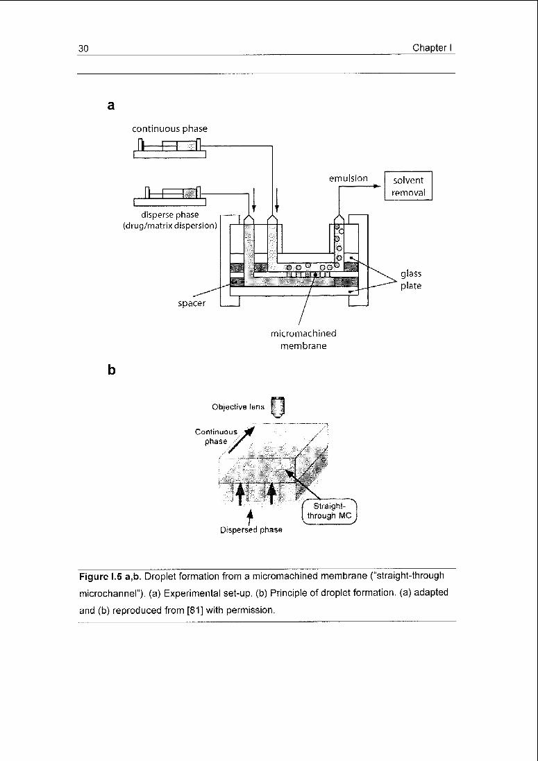
Figure 1.5 a,b. Droplet formation from a micromachined membrane ("straight-through
microchannel"). (a) Experimental set-up. (b) Principle of droplet formation, (a) adapted
and (b) reproduced from [81] with permission.

Chapter I 31
iû\46mm/s 1.80 kPa.
#* f
m M* *•'
*» fr'
#tf ,r'
1.80 kPa
yf9W
Figure i.5 c. Droplet formation from a micromachined membrane ("straight-through mi¬
crochannel"). (c) Left: Droplets forming from a membrane with oblong pores. Right:
Monodisperse droplets of soybean oil dispersed in an aqueous SDS solution formed
from said oblong micropore device. Reproduced from [81] with permission.
with the negatively charged glass membranes, the non-ionic surfactants were
soluble in both the aqueous phase and DCM so that they did not adsorb suffi¬
ciently at the interface, and PVA was assumed to partition to slowly to the inter¬
face upon droplet formation. Furthermore, uniform microspheres were only ob¬
tained when the aqueous continuous phase was pre-saturated with the polymer
solvent. When progesterone was co-dissolved in the PLA/PLGA solutions to
yield particles with a payload of up to 50%, no changes in the size and uniform¬
ity of the resulting microspheres was observed. A SPG membrane of larger
pore size (5.2 urn) was also used to produce PLA microparticles [79]. PLA was
dissolved in DCM at high concentrations of 10 to 20% (w/w), along with dodecyl
alcohol or hexadecane as co-surfactant, which were used to reduce the solu¬
tion's hydrophilicity and, thereby, its wetting of the polar glass pores to yield
more uniform microspheres. An aqueous solution of PVA and SDS was em¬
ployed as continuous phase. The resulting microspheres were considerably lar¬
ger (mean diameters of 10-25 urn) than the membrane pores and moderately
polydisperse (CV = 10-15%). No consistent relationship between particle size or
polydispersity and polymer or co-surfactant concentrations was observed.
Moreover, the microspheres were not perfectly spherical, but elliptical and
hemispherical when made with dodecyl alcohol and hexadecane, respectively.
32 Chapter I
A hydrophilic polycarbonate membrane [80] and a micromachined silicon
chip (Fig. 1.5 a,b) [81], both featuring uniformly sized pores or holes, have also
been studied for emulsion formation. Although the emulsions were not used to
form microspheres, an interesting insight into droplet formation with such de¬
vices was achieved. Membranes of both materials with 10 u.m circular pores
yielded polydisperse droplets of up to about 100 urn for the emulsification of
soybean oil in an aqueous surfactant solution flowing parallel to the membrane.
With the polycarbonate membrane [80], the droplet mean size (along with
polydispersity) was lowered from approx. 70 to 20 u.m by increasing the con¬
tinuous phase flow velocity from 0.02 to 0.54 m/s. In agreement with observa¬
tions on glass membranes [78], anionic surfactants were superior to non-ionic
ones, while cationic surfactants hampered droplet formation. Silicon chips with
oblong holes of 17.3 urn equivalent diameter yielded highly uniform (CV < 1.5%)
droplets of 32.5 urn average diameter (Fig. 1.5 c) [81]. Here, droplet size and
polydispersity remained unaffected by variations in the very low (0-9.2 mm s"1)
continuous phase velocity. Hence, it was concluded that the microdroplets de¬
tach spontaneously from the oblong channels due to instability of the elongated
interface at the channel outlet without the need of the continuous phase shear¬
ing action. The productivity per channel plate (5,000 channels) amounted to
6.5 ml/h of disperse phase.
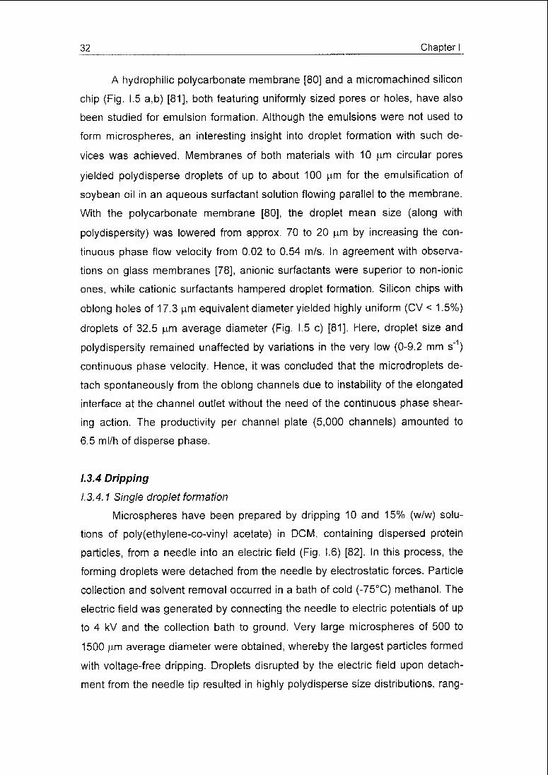
1,3,4 Dripping
1.3.4.1 Single droplet formation
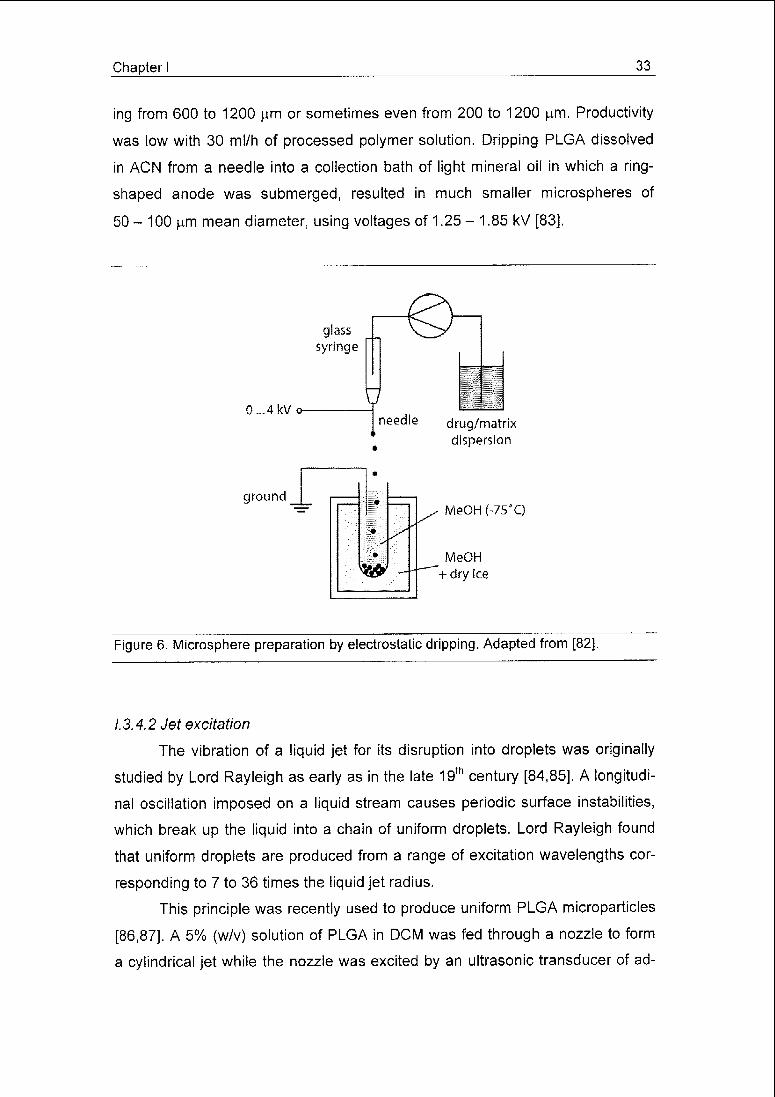
Microspheres have been prepared by dripping 10 and 15% (w/w) solu¬
tions of poly(ethylene-co-vinyl acetate) in DCM, containing dispersed protein
particles, from a needle into an electric field (Fig. 1.6) [82]. In this process, the
forming droplets were detached from the needle by electrostatic forces. Particle
collection and solvent removal occurred in a bath of cold (-75°C) methanol. The
electric field was generated by connecting the needle to electric potentials of up
to 4 kV and the collection bath to ground. Very large microspheres of 500 to
1500 urn average diameter were obtained, whereby the largest particles formed
with voltage-free dripping. Droplets disrupted by the electric field upon detach¬
ment from the needle tip resulted in highly polydisperse size distributions, rang-
Chapter I 33
ing from 600 to 1200 u,m or sometimes even from 200 to 1200 urn. Productivity
was low with 30 mi/h of processed polymer solution. Dripping PLGA dissolved
in ACN from a needle into a collection bath of light mineral oil in which a ring-
shaped anode was submerged, resulted in much smaller microspheres of
50 - 100 urn mean diameter, using voltages of 1.25 - 1.85 kV [83],
glass
syringe
0...4kVo-
ground
needle drug/matrix
dispersion
MeOH (-75*Q
MeOH
+ dry ice
Figure 6. Microsphere preparation by electrostatic dripping. Adapted from [82].
1.3.4.2 Jet excitation
The vibration of a liquid jet for its disruption into droplets was originally
studied by Lord Rayleigh as early as in the late 19th century [84,85]. A longitudi¬
nal oscillation imposed on a liquid stream causes periodic surface instabilities,
which break up the liquid into a chain of uniform droplets. Lord Rayleigh found
that uniform droplets are produced from a range of excitation wavelengths cor¬
responding to 7 to 36 times the liquid jet radius.
This principle was recently used to produce uniform PLGA microparticles
[86,87]. A 5% (w/v) solution of PLGA in DCM was fed through a nozzle to form
a cylindrical jet while the nozzle was excited by an ultrasonic transducer of ad-

34 Chapter I
justable frequency (Fig. 1.7 a). The particles were collected in 1% (w/v) PVA so¬
lution for solvent extraction/evaporation. Very uniform microspheres of 45 to
500 |im diameter were produced by jetting the polymer solution from nozzles of
different orifice size (Fig. 1.7 b,c). Generally, 95% of the microspheres were
within 1.5 (am of the average diameter. At fixed feed rate (2-3 ml/min; 60 (am
nozzle), the microsphere size could be adjusted between 70 and 130 urn by de¬
creasing the frequency from 70 to 19 kHz. Augmenting the feed rate at fixed ex¬
citation frequency from 2 to 3 ml/min resulted in a 30% increase in the
drug/matrix dispersion
,iH=m
sheath fluid
sheath fluid
drug/matrix
dispersion
frequencygenerator
r\j
piezoelectrictransducer
nozzle #1
nozzle #2
droplet collection/
solvent removal
Figure 1.7 a. Microencapsulation by jet excitation, (a) Schematic representation of the
process. Adapted from [86].

Chapter I 35
30 \
a
aï ">(\
a
9
z. 10
uJL
20 40 60
Diameter (jim)
80
Figure I.7 b,c. Microencapsulation by jet excitation, (b) Size distributions and (c) SEM
picture of PLGA microspheres produced by jet excitation. Scale bar in (c) represents
100 urn. (b) and (c) reproduced from [87] with permission.
microsphere diameter. Predetermined size distributions were obtained by
switching the excitation frequency during production. Generally, the size of the
microspheres was slightly larger than the diameter of the nozzle. Therefore,
particle sizes below 25 u,m are difficult to achieve with this technique as the
pressure drop across the orifice opening rapidly increases as does the risk of
orifice clogging. Scale-up is achieved using multi-orifice nozzles [e.g.88]. Multi-

36 Chapter I
orifice nozzles with non-uniform openings were designed to yield desired micro¬
sphere size distributions [89].
The jet of drug/matrix dispersion may be surrounded by an annular
stream of extraction fluid or any other suitable fluid immiscible with the
drug/matrix dispersion (Fig. 1.7 a). The biphasic jet is then again vibrated and
disintegrated into biphasic droplets [86,90]. The outer layer of fluid around the
droplets of drug/matrix dispersion protected the latter from deformation upon
impact with the collection/extraction fluid bath [91,92], Feeding the outer stream
at a higher velocity than the inner stream of drug/matrix dispersion stretched
and thinned the latter due to the friction between the two phases. Subsequent
vibration of the biphasic jet yielded uniform particles as small as 5 urn produced
from a nozzle of much larger diameter [86]. The combined control of exciting
frequency and annular sheath stream velocity allowed for a wide range of parti¬
cle sizes manufactured from a single nozzle. The annular stream may alterna¬
tively be employed to dissolve a second matrix material, allowing for the manu¬
facture of core/(multi)shell microspheres [90,92].
1.4 Solvent removal
In both, solvent extraction and evaporation, the solvent of the disperse
phase, i.e., the drug/matrix dispersion, must be slightly soluble in the continuous
phase so that partitioning into the continuous phase can occur leading to pre¬
cipitation of the matrix material. In solvent evaporation, the capacity of the con¬
tinuous phase is insufficient to dissolve the entire volume of disperse phase sol¬
vent. Therefore, the solvent must evaporate from the surface of the dispersion
to yield sufficiently hardened microspheres. In solvent extraction, the amount
and composition of the continuous phase is chosen so that the entire volume of
disperse phase solvent can be dissolved.
Generally, a continuous phase that is a non-solvent for the microencap¬
sulated bioactive compound is favourable. While for lipophilic compounds,
aqueous solutions may be comfortably chosen, the use of hydrophobic, organic
liquids as continuous phase for the encapsulation of hydrophilic compounds
[e.g. 57,93,94] is more delicate. Hydrophobic extraction fluids may not be read-
Chapter I 37
ily removed from the final product, potentially causing undesired residues.
Therefore, aqueous solutions are frequently used as continuous phase, even for
the microencapsulation of hydrophilic compounds. Here, loss of bioactive com¬
pound is typically prevented by increasing the concentration of the matrix mate¬
rial solution; the resulting higher viscosity restricts the migration of the bioactive
compound from the solidifying microspheres to the external phase by means of
lowered diffusion and increased stability of the drug/matrix dispersion
[33,48,95]. Other means of preventing loss of bioactive material into the con¬
tinuous phase encompass the adaptation of the continuous phase pH to lower
the solubility of the bioactive compound [50], or the addition of electrolytes to
increase the osmotic pressure of the continuous phase [96,97,98].
The ideal rate of solvent removal depends on a variety of factors like the
type of matrix material, drug and solvent, as well as the desired release profile
of the microspheres. For example, fast microsphere solidification will be pre¬
ferred if the drug easily partitions into the continuous phase. On the other hand,
slow solidification favours denser over more porous microspheres, affecting the
drug release.
1.4.1 Evaporation
The rate of volatile solvent removal from the solidifying microspheres can
be controlled by the temperature of the microsphere dispersion. Higher tem¬
peratures will facilitate the evaporation of the solvent from the continuous phase
and thereby maintain a high concentration gradient for the solvent between the
microspheres and the continuous phase. In two similar studies on the encapsu¬
lation of BSA in a PLGA-PEG blend [99] and in pure PLGA [100], both dissolved
in DCM and using an aqueous PVA solution as continuous phase, the influence
of the temperature (4-42 °C) at which the resulting dispersion was stirred for
30 min was examined. Maintaining the temperature, the dispersion was thereaf¬
ter diluted with additional continuous phase until a defined volume was attained.
The PLGA microspheres tended to be larger when prepared at higher tempera¬
tures (38 and 42 °C), showed wider size distributions and decreased particle
density compared to those prepared at lower temperatures (4-33 °C). As 38 and
42 °C are close to or even above the boiling point of the solvent DCM
38 Chapter I
(b.p. » 40 °C), these findings were attributed to very rapid microsphere solidifi¬
cation with insufficient mixing time to reduce droplet size. With PLGA, the mor¬
phology of the particle interior (honeycomb-like) and BSA encapsulation effi¬
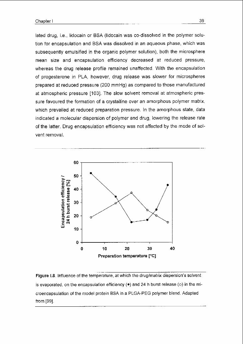
ciency (53 to 63%) were unaffected by the preparation temperature while for the
PLGA-PEG blend, BSA encapsulation appeared to be temperature-sensitive
with a minimum efficiency of 15% obtained at 22°C, which steadily improved (up
to 52%) for lower and higher temperatures (Fig. 1.8). For both polymers, the
burst (24 h) release was highest at intermediate preparation temperatures,
while values continuously decreased for higher and lower temperatures
(Fig. 1.8). For the PLGA-PEG microspheres, these phenomena were explained
by a fast skin formation at the extremes of temperature range studied, restrict¬
ing BSA transport to the microspheres' periphery and loss of the protein. At high
temperatures, rapid solvent evaporation obviously leads to fast solvent deple¬
tion in the microspheres. The authors' hypothesis for the low temperature effect
was an increased DCM solubility in water.
When salmon calcitonin (sCT) was encapsulated into PLGA using a tem¬
perature gradient to remove the solvent, hollow microspheres with porous walls
were obtained [101], An aqueous solution of sodium oleate was used as con¬
tinuous phase and the temperature of the resulting dispersion was increased
from 15 to 40°C. A rapid temperature increase within 30 min led to particles with
a large empty core and a thin wall, while a gradual or a stepwise increase over
200 min resulted in increased wall thickness. Peptide incorporation, however,
was largely unaffected by the solvent removal conditions. The formation of the
hollow core, which was not found when the solvent was removed by extraction,
was attributed to the slow removal of methanol in the evaporation process;
methanol was used as co-solvent for the dissolution of sCT in the polymer sol¬
vent DCM.
As an alternative to elevated temperatures, reduced pressure is some¬
times used to promote the evaporation of the solvent, as in the encapsulation of
lidocain [14] or albumin [102] in small (0.7- 1.2 urn) PLA microspheres. In both
studies, an aqueous PVA solution was employed as the continuous phase.
Evaporation of the polymer solvent DCM was accomplished within 6 h at
760 mm Hg or 2 h at 460 or 160 mm Hg at 25°C. Irrespective of the encapsu-
Chapter I 39
lated drug, i.e., lidocain or BSA (lidocain was co-dissolved in the polymer solu¬
tion for encapsulation and BSA was dissolved in an aqueous phase, which was
subsequently emulsified in the organic polymer solution), both the microsphere
mean size and encapsulation efficiency decreased at reduced pressure,
whereas the drug release profile remained unaffected. With the encapsulation
of progesterone in PLA, however, drug release was slower for microspheres
prepared at reduced pressure (200 mmHg) as compared to those manufactured
at atmospheric pressure [103]. The slow solvent removal at atmospheric pres¬
sure favoured the formation of a crystalline over an amorphous polymer matrix,
which prevailed at reduced preparation pressure. In the amorphous state, data
indicated a molecular dispersion of polymer and drug, lowering the release rate
of the latter. Drug encapsulation efficiency was not affected by the mode of sol¬
vent removal.
60
50 -
>Ȇ ^"o"
40*= «
<ü o>
c ?>.2 +-
30*; <n« £
psul hbu 20
LU10 -
10 20 30
Preparation temperature [°C]
40
Figure 1.8. Influence of the temperature, at which the drug/matrix dispersion's solvent
is evaporated, on the encapsulation efficiency (•) and 24 h burst release (o) in the mi¬
croencapsulation of the model protein BSA in a PLGA-PEG polymer blend. Adapted
from [99].

40 Chapter I
1.4.2 Liquid extraction
Solvent extraction is frequently performed as a two-step process First,
the drug/matrix dispersion is mixed with a small amount of continuous phase to
yield an emulsion of desired droplet size (distribution) Then, further continuous
phase and/or additional extraction agents are added at an amount sufficient to
absorb the entire solvent leaching from the solidifying microspheres Nonethe¬
less, a patent application [104] teaches a one-step solvent extraction process
Without prior emulsification step, the drug/matrix dispersion is immediately ho¬
mogenised with such a quantity of continuous phase that is capable of dissolv¬
ing the total amount of disperse phase solvent at once However, this process
requires careful settings of the physicochemical parameters during the homog-
enisation step in order to yield homogenously dispersed particles
A number of publications have reported that the drug substance can be
more efficiently retained in the microspheres, if the amount of continuous phase
strongly exceeds that theoretically necessary for dissolving the disperse phase
solvent [e g 105] The rapid formation of a skin on the microspheres' periphery
reduces the loss of drug to the continuous phase, which is of special importance
when the latter is a good solvent for the drug For example, the use of 10-fold
the amount of fluid necessary to extract all the disperse phase solvent is sug¬
gested for the encapsulation of substances that are sparingly to freely soluble
(> 10 mg/ml) in the continuous phase [105]
Rather than adding the entire amount of continuous phase at once, it
may be added continuously over an extended period of time However, in a sys¬
tem composed of aqueous BSA dispersed in a solution of PLA in DCM and
0 05% aqueous PVA solution, stirred at constant rate in a beaker for 30 mm,
further addition of continuous phase at constant rates ranging from 1 5 to
9 ml/mm exerted no significant influence on the microspheres' characteristics
[99] Likewise, in a similar process using a fixed addition rate but different final
volumes of continuous phase, no significant influence on the resulting sCT-
loaded microspheres was observed [101] A continuously operated alternative
to the batch-mode metering of continuous phase into a beaker consists in intro¬
ducing further continuous phase or additional extraction-promoting agents
through a series of feed streams into a continuous flow of dispersed nascent
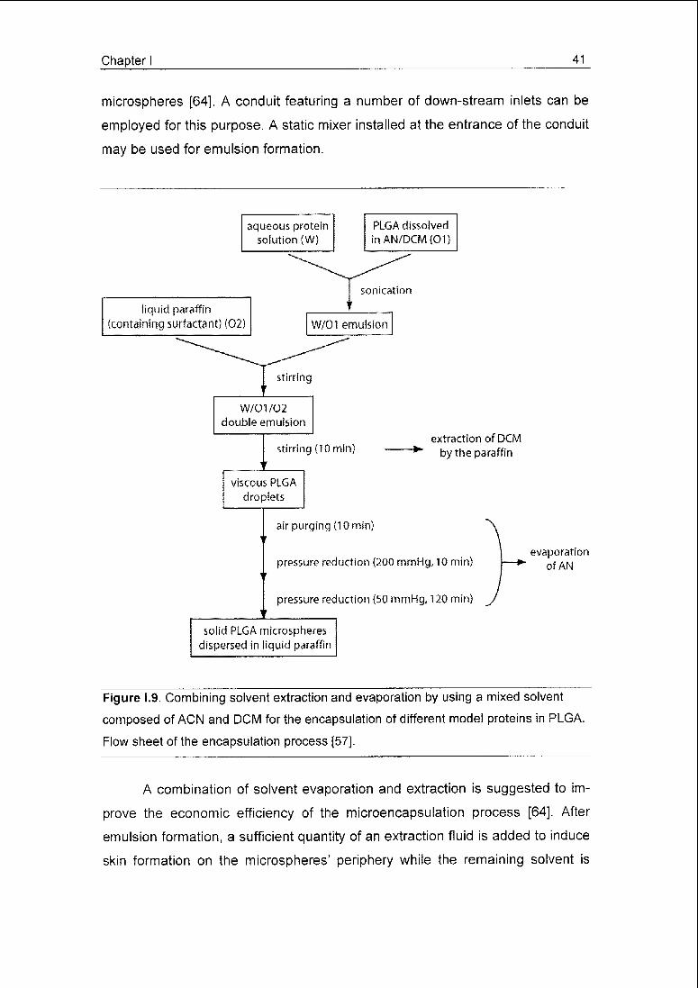
Chapter I 41
microspheres [64], A conduit featuring a number of down-stream inlets can be
employed for this purpose. A static mixer installed at the entrance of the conduit
may be used for emulsion formation.
aqueous proteinsolution (W)
PLGA dissolved
inAN/DCM(01)
liquid paraffin
(containing surfactant) (02)
sonicatton
W/01 emulsion
W/01/02
double emulsion
stirring (10 min)extraction of DCM
"*"by the paraffin
viscous PLGA
droplets
air purging (10 min)
pressure reduction (200 mmHg, 10 min)
pressure reduction (50 mmHg, 120 min)
evaporationof AN
solid PLGA microspheres
dispersed in liquid paraffin
Figure 1.9. Combining solvent extraction and evaporation by using a mixed solvent
composed of ACN and DCM for the encapsulation of different model proteins in PLGA.
Flow sheet of the encapsulation process [57].
A combination of solvent evaporation and extraction is suggested to im¬
prove the economic efficiency of the microencapsulation process [64]. After
emulsion formation, a sufficient quantity of an extraction fluid is added to induce
skin formation on the microspheres' periphery while the remaining solvent is

42 Chapter I
removed by evaporation. The brief skin-forming extraction step prior to evapora¬
tion minimises the loss of drug during the following evaporation procedure while
the volume of extraction fluid consumed is reduced as compared to an extrac¬
tion process alone.
The two steps of solvent extraction and evaporation may be combined by
using a mixed solvent system [57]. For example, a system has been studied
consisting of an aqueous protein solution, which was dispersed in a solution of
PLGA in a mixture of ACN and DCM (Fig. 1.9). The drug/matrix dispersion was
emulsified in liquid paraffin containing sorbitan mono-oleat. The production ves¬
sel was then purged with air and thereafter put stepwise under reduced pres¬
sure (300/50 mmHg). The moderately polar DCM is extracted by the paraffin,
whereas the strongly polar ACN, which is not soluble in paraffin, is evaporated
during the purging and evacuating steps. BSA and lysozyme were very effi¬
ciently encapsulated, i.e. at 93 and 91%, respectively, while lower values were
obtained for gelatin (71%) and a decapeptide (25-46%). After the extraction of
DCM, the remaining ACN is miscible with the water dissolving the protein caus¬
ing precipitation of BSA and lysozyme, while the decapeptide remained dis¬
solved enhancing its potential to escape encapsulation.
Solvent extraction, evaporation and a combined procedure were com¬
pared for the entrapment of ovalbumin (OVA) in PLGA microspheres [106].
Aqueous OVA solution was intensely homogenised in a solution of PLGA in
DCM. The drug/matrix dispersion was further emulsified in either water (solvent
evaporation), a 1:1 water-methanol mixture (combined mechanism) or solely
methanol (extraction) as continuous phases, using polyvinyl pyrrolidone) (PVP)
as an emulsifier. OVA entrapment was approx. 10% with the combined and the
pure extraction processes, but only 7.5% with the evaporation method. As DCM
is much more soluble in methanol than in water, the presence of the alcohol led
to faster solvent removal and thus improved drug entrapment.
Two patents [107,108] teach methods for in-process reprocessing and
recycling of the continuous phase to minimise waste. A portion of continuous
phase rich in disperse phase solvent is repeatedly or continuously withdrawn
from the suspension of nascent microspheres, deprived of part of the solvent
and re-fed to the microsphere suspension. Solvent removal is achieved by ex-
Chapter I 43
posing the said portion of continuous phase to either a gas separation mem¬
brane [107] on which a vacuum is applied, or to an absorption fluid of high dis¬
solution capacity for the disperse phase solvent, using a liquid-liquid column
[108].
1.5 Microsphere harvest and drying
Separation of the solidified microspheres from the continuous phase is
usually done either by filtration or centrifugation. The particles may then be
rinsed with appropriate liquids to remove adhering substances such as disper¬
sion stabilisers or non-encapsulated drugs. Rinsing may involve elevated tem¬
peratures or the use of extraction agents to reduce the amount of residual sol¬
vent in the microspheres [109], Finally, the microspheres are dried either at am¬
bient conditions or under reduced pressure, heat or by lyophilisation to yield a
free-flowing powder. The drying procedure removes not only continuous phase
and wash fluid adhering to the microspheres' surface, but also traces of sol¬
vents and continuous phase from the interior of the particles. Thus, the condi¬
tions and rate of drying influence the amount of solvent and moisture residue
[110], microsphere morphology and porosity as well as drug re-crystallisation
inside the spheres, and are therefore likely to affect the release behaviour of the
final product.
1.6 Conclusions
The widespread interest in microencapsulated drugs brought forth the
need to prepare such particles in larger quantities and in sufficient quality suit¬
able for clinical trials and commercialisation. The most frequently described sol¬
vent extraction/evaporation-based technology using simple beaker/stirrer set-up
is inappropriate for producing larger amounts of microspheres in an economic,
robust and well-controlled manner. Static mixers warrant continuous production
and simple scale-up, while the extrusion through porous membranes or micro-
channels, integrated in small-scaled equipment that is easy to operate and ster¬
ilise, additionally offers improved control of the microsphere size distribution as

44 Chapter I
compared to classical mixing processes. Further, jet excitation is powerful in
combining productivity and microsphere size control. Solvent removal by evapo¬
ration may be accelerated using elevated temperatures or reduced pressure.
The rapid solvent extraction may require relatively large amounts of processing
fluids and their subsequent recycling. Therefore, combined extraction and
evaporation represents a compromise in terms of both time- and waste-efficient
microsphere production.
References
[1] P. Johansen, Y. Men, H.P. Merkle, B. Gander, Revisiting PLA/PLGA mi¬
crospheres: an analysis of their potential in parenteral vaccination, Eur.
J. Pharm. Biopharm. 50 (2000) 129-146.
[2] J. Hanes, J.L. Cleland, R. Langer, New advances in microsphere-based
single-dose vaccines Adv. Drug Deliv. Rev. 28 (1997) 97-119.
[3] E. Walter, D. Dreher, M. Kok, L. Thiele, S.G. Kiama, P. Gehr, H.P.
Merkle, Hydrophilic poly(DL-lactide-co-glycolide) microspheres for the
delivery of DNA to human-derived macrophages and dendritic cells, J.
Control. Release 76 (2001) 149-168
[4] S. Faraasen, J. Vörös, G. Csucs, M. Textor, H.P. Merkle, E. Walter,
Ligand-specific targeting of microspheres to phagocytes by surface modi¬
fication with poly(L-lysine)-grafted poly(ethylene glycol) conjugate,
Pharm. Res. 20 (2003) 237-246.
[5] B. Lu,J.Q. Zhang, H. Yang, Lung-targeting microspheres of carboplatin,
Int. J. Pharm. 265(2003)1-11.
[6] A. Smith, I.M. Hunneyball, Evaluation of poly(lactic acid) as a biodegrad¬
able drug delivery system for parenteral administration, Int. J. Pharm. 30
(1986)215-220.
[7] J.M. Anderson, M.S. Shive, Biodegradation and biocompatibility of PLA
and PLGA microspheres, Adv. Drug. Deliv. Rev. 28 (1997) 5-24.
[8] R.L. Cleek, K.C. Ting, S.G. Eskin, A.G. Mikos, Microparticles of poly(DL-
lactic-co-glycolic acid) / poly(ethylene glycol) blends for controlled drug
delivery, J. Control. Release 48 (1997) 259-268.
Chapter I 45
[9] Y. Kato, H. Onishi, Y. Machida, Application of chitin and chitosan deriva¬
tives in the pharmaceutical field, Curr. Pharm. Biotechnol. 4 (2003) 303-
309.
[10] H. Reithmeier, J. Herrmann, A. Göpferich, Lipid microparticles as a par¬
enteral controlled release device for peptides, J. Control. Release 73
(2001)339-350.
[11] M. Boisdron-Celle, P. Menei, J.P. Benoit, Preparation and characteriza¬
tion of 5-fluorouracil-loaded microparticles as biodegradable anticancer
drug carriers, J. Pharm. Pharmacol. 47 (1995) 108-114.
[12] R. Verrijk, I.J. Smolders, N. Bosnie, A.C. Begg, Reduction of systemic
exposure and toxicity of cisplatin by encapsulation in poly(lactide-co-
glycolide), Cancer Res. 52 (1992) 6653-6656.
[13] S. Yolles, T.D. Leafe, J.H. Woodland, F.J. Meyer, Long acting delivery
systems for narcotic antagonists. 2. Release rates of naltrexone from
poly(lactic acid) composites, J. Pharm. Sei. 64 (1975) 348-349.
[14] T.W. Chung, Y.Y. Huang, Y.Z. Liu, Effects of the rate of solvent evapora¬
tion on the characteristics of drug loaded PLLA and PDLLA micro¬
spheres, Int. J. Pharm. 212 (2001) 161-169
[15] P. Couvreur, M.J. Blanco-Prieto, F. Puisieux, B. Roques, E. Fattal, Multi¬
ple emulsion technology for the design of microspheres containing pep¬
tides and oligopeptides, Adv. Drug Deliv. Rev. 28 (1997) 85-96.
[16] R. Jeyanthi, R.C. Mehta, B.C. Thanoo, P.P. DeLuca, Effect of processing
parameters on the properties of peptide-containing PLGA microspheres,
J. Microencapsulation 14 (1997) 163-174.
[17] L. Meinel, O.E. Uli, J. Zapf, M. Malfanti, H.P. Merkle, B. Gander, Stabiliz¬
ing insulin-like growth factor-l in poly(DL,lactide-co-glycolide) micro¬
spheres, J. Control. Release 70 (2001) 193-202.
[18] S. Cohen, T. Yoshioka, M. Lucarelli, L.H. Hwang, R. Langer, Controlled
delivery systems for proteins based on poly(lactic/glycolic acid) micro¬
spheres Pharm. Res. 8 (1991) 713-720.

46 Chapter I
[19] Y.Y. Hsu, T. Hao, M.L. Hedley, Comparison of process parameters for
microencapsulation of plasmid DNA in poly(D,L-lactic-co-glycolic) acid
microspheres, J. Drug Target. 7 (1999) 313-323.
[20] Y. Capan, B.H. Woo, S. Gebrekidan, S. Ahmed, P.P. DeLuca, Influence
of formulation parameters on the characteristics of poly(D,L-lactide-co-
glycolide) microspheres containing poly(L-lysine) complexed plasmid
DNA, J. Control. Release 60 (1999) 279-286.
[21] C. Sturesson, P. Artursson, R. Ghaderi, K. Johansen, A, Mirazimi, I. Uh-
noo, L. Svensson, A.C. Albertsson, J. Carlfors, Encapsulation of rotavirus
into poly(lactide-co-glycolide) microspheres, J. Control. Release 59
(1999)377-389.
[22] N. Kofler, C. Ruedl, J. Klima, H. Recheis, G. Bock, G. Wick, H. Wolf,
Preparation and characterization of poly-(D,L-lactide-co-glycolide) and
poly-(L-lactic acid) microspheres with entrapped pneumotropic bacterial
antigens, J. Immunol. Meth. 192 (1996) 25-35.
[23] J.M. Ren, Q.M. Zou, F.K. Wang, Q.A. He, W. Chen, W.K. Zen, PELA mi¬
crospheres loaded H__pylori lysates and their mucosal immune response,
World J. Gastroenter. 8 (2002) 1098-1102.
[24] C. Aftabrouchad, E. Doeiker, Méthodes de preparation des microparticu¬
les biodégradables chargées en principes actifs hydrosolubles, S.T.P.
Pharma Sciences 2 (1992) 365-380.
[25] P. Johansen, H.P. Merkle, B. Gander, Technological considerations re¬
lated to the up-scaling of protein microencapsulation by spray-drying,
Eur. J. Pharm. Biopharm. 50 (2000) 413-417.
[26] C. Thomasin, P. Johansen, R. Alder, R. Bemsel, G. Hottinger, H. Altorfer,
A.D. Wright, E. Wehrli, H.P. Merkle, B. Gander, A contribution to over¬
coming the problem of residual solvents in biodegradable microspheres
prepared by coacervation, Eur, J. Pharm. Biopharm. 42 (1996) 16-24.
[27] R.F. Falk, T.W. Randolph, Process variable implications for residual sol¬
vent removal and polymer morphology in the formation of gentamycin-
loaded poly(L-lactide) microparticles, Pharm. Res. 15 (1998) 1233-1237.

Chapter I 47
[28] J. Jung, M. Perrut, Particle design using supercritical fluids: Literature
and patent survey, J. Supercrit. Fluid 20 (2001) 179-219.
[29] J. Herrmann, R. Bodmeier, Biodegradable, somatostatin acetate contain¬
ing microspheres prepared by various aqueous and non-aqueous solvent
evaporation methods, Eur. J. Pharm. Biopharm. 45 (1998) 75-82.
[30] Y.F. Maa, C.C. Hsu, Performance of sonication and microfluidization for
liquid-liquid emulsification, Pharm. Dev. Technol. 4 (1999) 233-240.
[31] S.H. Lyons, S.G. Wright, Apparatus and method for preparing microparti¬
cles using in-line solvent extraction, US Patent 6,495,166, 2002.
[32] Y.F. Maa, C.C. Hsu, Effect of primary emulsions on microsphere size
and protein-loading in the double emulsion process, J. Microencapsul. 14
(1997)225-241.
[33] H. Rafati, A.G. Coombes, J. Adler, J. Holland, S.S. Davis, Protein-loaded
poly(DL-lactide-co-glycolide) microparticles for oral administration: formu¬
lation, structural and release characteristics, J. Control. Release 43
(1997)89-102.
[34] M.J. Blanco Prieto, F. Delie, E. Fattal, A. Tartar, F. Puisieux, A. Gulik, P.
Couvreur, Characterization of V3 BRU peptide-loaded small PLGA mi¬
crospheres prepared by a (w1/o)w2 emulsion solvent evaporation
method, Int. J. Pharm. 111 (1994) 137-145.
[35] Y.Y. Yang, T.S. Chung, N.P. Ng, Morphology, drug distribution, and in
vitro release profiles of biodegradable polymeric microspheres containing
protein fabricated by double emulsion solvent extraction/evaporation
method, Biomaterials 22 (2001) 231-241.
[36] H. Sah, R. Toddywala, Y.W. Chien, The influence of biodegradable
microcapsule formulations on the controlled release of a protein, J. Con¬
trol. Release 30 (1994) 201-211.
[37] H. Jeffery, S.S. Davis, D.T. O'Hagan, The preparation and characteriza¬
tion of poly(lactide-co-glycolide) microparticles. II. The entrapment of a
model protein using a (water-in-oil)-in water emulsion solvent evapora¬
tion technique, Pharm. Res. 10 (1993) 362-368.

48 Chapter I
[38] H. Marchais, F. Boury, C. Damgé, J.E. Proust, J.P. Benoit, Formulation
of bovine serum albumin loaded PLGA microspheres. Influence of the
process variables on the loading and in vitro release, STP Pharm. Sei. 6
(1996)417-423.
[39] J. Herrmann, R. Bodmeier, Somatostatin containing biodegradable mi¬
crospheres prepared by a modified solvent evaporation method based on
W/O/W-multiple emulsions, int. J. Pharm. 126 (1995) 129-138.
[40] T. Uchida, K. Yoshida, A. Ninomiya, S. Goto, Optimization of preparative
conditions for polylactide (PLA) microspheres containing ovalbumin,
Chem. Pharm. Bull. 43 (1995) 1569-1573.
[41] Y.Y. Yang, T.S. Chung, X.L. Bai, W.K. Chan, Effect of preparation condi¬
tions on morphology and release profiles of biodegradable polymeric mi¬
crospheres containing protein fabricated by double-emulsion method,
Chem. Eng. Sei. 55 (2000) 2223-2236.
[42] G. Crotts, T.G. Park, Preparation of porous and nonporous biodegrad¬
able polymeric hollow microspheres, J. Control. Release 35 (1995) 91-
105.
[43] W. Al-Azzam, E.A. Pastrana, K. Griebenow, Co-lyophilization of bovine
serum albumin (BSA) with poly(ethylene glycol) improves efficiency of
BSA encapsulation and stability in polyester microspheres by a solid-in-
oil-in-oil technique, Biotechnol. Lett. 24 (2002) 1367-1374.
[44] M.A. Tracy, Development and scale-up of a microsphere protein delivery
system, Biotechnol. Prog. 14 (1998) 108-115.
[45] H.R. Constantino, W.E. Jaworowicz, M.A. Tracy, C.P. Beganski, Method
of producing sub-micron particles of biologically active agents and uses
thereof, US Patent 6,284,283, 2001.
[46] T. Morita, Y. Sakamura, Y. Horikiri, T. Suzuki, H. Yoshino, Protein en¬
capsulation into biodegradable microspheres by a novel S/OAA/ emulsion
method using poly(ethylene glycol) as a protein micronization adjuvant,
J. Control. Release 69 (2000) 435-444.
Chapter I 49
[47] N. Nihant, C. Schugens, C. Grandfils, R. Jérôme, P. Teyssié, Polylactide
microparticles prepared by double emulsion/evaporation technique. I. Ef¬
fect of primary emulsion stability, Pharm. Res. 11 (1994) 1479-1484.
[48] C. Schugens, N. Laruelle, N. Nihant, C. Grandfils, R. Jérôme, P. Teyssié,
Effect of the emulsion stability on the morphology and porosity of
semicrystalline poly l-lactide microparticles prepared by w/o/w double
emulsion-evaporation, J. Control. Release 32 (1994) 161-176.
[49] Y. Ogawa, M. Yamamoto, H. Okada, T. Yashiki, T. Shimamoto, A new
technique to efficiently entrap leuprolide acetate into microcapsules of
polylactic acid or copoly(lactic/glycolic) acid, Chem. Pharm. Bull. 36
(1988) 1095-1103.
[50] M.J. Blanco Prieto, E. Fattal, A. Gulik, J.C. Dedieu, B.P. Roques, P.
Couvreur, Characterization and morphological analysis of chole-
cystokinin derivative peptide-loaded poly(lactide-co-glycolide) micro¬
spheres prepared by a water-in-oil-in-water emulsion solvent evaporation
method, J. Control. Release 43 (1997) 81-87.
[51] I. Soriano, A. Delgado, R.V. Diaz, C. Evora, Use of surfactants in polylac¬
tic acid protein microspheres, Drug Dev. Ind. Pharm. 21 (1995) 549-558.
[52] D. Blanco, M.J. Alonso, Protein encapsulation and release from
poly(lactide-co-glycolide) microspheres: effect of the protein and polymer
properties and of co-encapsulation of surfactants, Eur. J. Pharm. Bio¬
pharm. 45 (1998) 285-294.
[53] P. Sansdrap, A.J. Moës, Influence of manufacturing parameters on the
size characteristics and the release profiles of nifedipine from poly(DL-
lactide-co-glycolide) microspheres, Int. J. Pharm. 98 (1993) 157-164.
[54] F. Gabor, B. Ertl, M. Wirth, R. Mallinger, Ketoprofen-poly(D,L-iactic-co-
glycolic acid) microspheres: influence of manufacturing parameters and
type of polymer on the release characteristics, J. Microencapsulation 16
(1999) 1-12.
[55] T. Mateovic, B. Kriznar, M. Bogataj, A. Mrhar, The influence of stirring
rate on biopharmaceutical properties of Eudragit RS microspheres, J.
Microencapsulation 19 (2002) 29-36.

50 Chapter I
[56] A.G. Coombes, P.D. Scholes, M.C. Davies, L.lllum, S.S. Davis, Resorb¬
able polymeric microspheres for drug delivery - production and simulta¬
neous surface modification using PEO-PPO surfactants, Biomaterials 15
(1994)673-680.
[57] N. Badri Viswanathan, P.A. Thomas, J.K. Pandit, M.G. Kulkarni, R.A.
Mashelkar, Preparation of non-porous microspheres with high entrap¬
ment efficiency of proteins by a (water-in-oil)-in-oil emulsion technique, J.
Control. Release 58 (1999) 9-20.
[58] A. Carrio, G. Schwach, J. Coudane, M. Vert, Preparation and degrada¬
tion of surfactant-free PLAGA microspheres, J. Control Release 37
(1995) 113-121.
[59] H. Jeffery, S.S. Davis, D.T. O'Hagan, The preparation and characterisa¬
tion of poly(lactide-co-glycolide) microparticles. I. Oil-in-water emulsion
solvent evaporation, Int. J. Pharm. 77 (1991) 169-175.
[60] H. Sah, Microencapsulation techniques using ethyl acetate as a dis¬
persed solvent: effects of its extraction rate on the characteristics of
PLGA microspheres, J. Control. Release 47 (1997) 233-245.
[61] Y.F. Maa, C. Hsu, Microencapsulation reactor scale-up by dimensional
analysis, J. Microencaps. 13 (1996) 53-66.
[62] Y.F. Maa, C. Hsu, Liquid-liquid emulsification by static mixers for use in
microencapsulation, J. Microencapsulation 13 (1996) 419-433.
[63] S.L. Lyons, S.G. Wright, Apparatus and method for preparing microparti¬
cles, US Patent 6,331,317, 2001.
[64] J.W. Gibson, R.J. Holl, A.J. Tipton, Emulsion-based processes for mak¬
ing microparticles, US Patent 6,291,013, 2001.
[65] N. Leelarasamee, S.A. Howard, C.J. Malanga, J.K. Ma, A method for the
preparation of polylactic acid microcapsules of controlled particle size
and drug loading, J. Microencapsulation 5 (1988) 147-157.
[66] . Amsden, The production of uniformly sized polymer microspheres,
Pharm. Res. 16(1999) 1140-1143.
[67] B.G. Amsden, R.T. Liggins, Methods for microsphere production, US
Patent 6,224,794, 2001.
Chapter I 51
[68] S. Freitas, A. Walz, H.P. Merkle, B. Gander, Solvent extraction employ¬
ing a static micromixer: a simple robust and versatile technology for the
microencapsulation of proteins, J. Microencapsulation 20 (2003) 67-85.
[69] V. Haverkamp, W. Ehrfeld, K. Gebauer, V. Hessel, H. Loewe, T. Richter,
C. Wille, The potential of micromixers for contacting of disperse liquid
phases, Fresen. J. Anal. Chem. 364 (1999) 617-624.
[70] S. Sugiura, M. Nakajima, S. Iwamoto, M. Seki, Interfacial tension driven
monodispersed droplet formation from microfabricated channel array,
Langmuir 17 (2001) 5562-5566.
[71] I. Kobayashi, Y. litaka, S. Iwamoto, S. Kimura, M. Nakajima, Preparation
characteristics of lipid microspheres using microchannel emulsification
and solvent evaporation methods, J. Chem. Eng. Jpn. 36 (2003) 996-
1000.
[72] T. Kawakatsu, H. Komori, M. Nakajima, Y. Kikuchi, T. Yonemoto, Pro¬
duction of monodispersed oil-in-water emulsion using crossflow-type sili¬
con microchannel plate, J. Chem. Eng. Jpn. 32 (1999) 241-244.
[73] S. Sugiura, M. Nakajima, M. Seki, Preparation of monodispersed emul¬
sion with large droplets using microchannel emulsification, J. Am. Oil
Chem. Soc. 79 (2002) 515-519.
[74] S. Sugiura, M. Nakajima, M. Seki, Effect of channel structure in micro-
channel emulsification, Langmuir 18 (2002) 5708-5712.
[75] S. Sugiura, M. Nakajima, M. Seki, Prediction of droplet diameter for mi¬
crochannel emulsification, Langmuir 18 (2002) 3854-3859.
[76] S. Sugiura, M. Nakajima, N. Kumazawa, S. Iwamoto, M. Seki, Charac¬
terization of spontaneous transformation-based droplet formation during
microchannel emulsification, J. Phys. Chem. B 106 (2002) 9405-9409.
[77] N. Muramatsu, T. Kondo, An approach to prepare microparticles of uni¬
form size, J. Microencapsulation 12 (1995) 129-136.
[78] K. Shiga, N. Muramatsu, T. Kondo, Preparation of poly(D.L-lactide) and
copoly(lactide-glycolide) microspheres of uniform size, J. Pharm. Phar¬
macol. 48 (1996) 891-895.
52 Chapter I
[79] G. Ma, M. Nagai, S. Omi, Preparation of uniform poly(lactide) micro¬
spheres by employing the Shirasu Porous Glass (SPG) emulsification
technique, Colloid. Surface. A 153 (1999) 383-394.
[80] I. Kobayashi, M. Yasuno, S. Iwamoto, A. Shono, K. Satoh, M. Nakajima,
Microscopic observation of emulsion droplet formation from a polycar¬
bonate membrane, Colloid. Surface. A 207 (2002) 185-196.
[81] I. Kobayashi, M. Nakajima, K. Chun, Y. Kikuchi, H. Fujita, Silicon array of
elongated through-holes for monodisperse emulsion droplets, AlChE J.
48(2002)1639-1644.
[82] B.G. Amsden, M.F. Goosen, An examination of factors affecting the size,
distribution and release characteristics of polymer microbeads made us¬
ing electrostatics, J. Control. Release 43 (1997) 183-196.
[83] P.B. O'Donnell, M. Iwata, J.W. McGinity, Properties of multiphase micro¬
spheres of poly(D,L-lactic-co-glycolic acid) prepared by a Potentiometrie
dispersion technique, J. Microencapsulation 12 (1995) 155-163.
[84] L. Rayleigh, Proc. Lond. Math. Soc. 10 (1879) 4.
[85] L. Rayleigh, Philos. Mag. S.G. 14 (1882) 184.
[86] C. Berkland, K. Kim, D.W. Pack, Fabrication of PLG microspheres with
precisely controlled and monodisperse size distributions, J. Control. Re¬
lease 73 (2001) 59-74.
[87] C. Berkland, M. King, A. Cox, K. Kim, D.W. Pack, Precise control of PLG
microsphere size provides enhanced control of drug release rate, J. Con¬
trol. Release 82 (2002) 137-147.
[88] G. Brenn, F. Durst, C. Tropea, Monodisperse sprays for various pur¬
poses-their production and characteristics, Part. Part. Syst. Charact. 13
(1996) 179-185.
[89] G. Brenn, On the controlled production of sprays with discrete polydis¬
perse drop size spectra, Chem. Eng. Sei. 55 (2000) 5437-5444.
[90] C.W. Hatcher, M.J. Fulwyler, Method for producing uniform particles, US
Patent 4,162,282, 1979.
[91] I. Lombardo, P.J. Natale, Methods for promoting the formation of mi¬
croparticles, US Patent 4,390,484, 1983.
Chapter I 53
[92] K. Kyekyoon, D.W. Pack, CJ. Berkland, Microparticles, PCT Patent Ap¬
plication WO 02/13786, 2002.
[93] C. Sturesson, J. Carlfors, K. Edsman, M. Andersson, Preparation of bio¬
degradable poly(lactic-co-glycolic) acid microspheres and their in vitro re¬
lease of timolol maleate, Int. J. Pharm 89 (1993) 235-244.
[94] H.T. Wang, E. Schmitt, D.R. Flanagan, R.J. Linhardt, Influence of formu¬
lation methods on the in vitro controlled release of protein from
poly(ester) microspheres, J. Control. Release 17 (1991) 23-31.
[95] R.C. Metha, B.C. Thanoo, P.P. DeLuca, Peptide containing micro¬
spheres from low molecular weight and hydrophilic poly(DL-lactide-co-
glycolide), J. Control. Release 41 (1996) 249-257.
[96] X.M. Deng, X.H. Li, M.L. Yuan, CD. Xiong, Z.T. Huang, W.X. Jia, Y.H.
Zhang, Optimization of preparative conditions for poly-DL-lactide-
polyethylene glycol microspheres with entrapped Vibrio Cholera anti¬
gens, J. Control. Release 58 (1999) 123-131.
[97] K.F. Pistel, T. Kissel, Effects of salt addition on the microencapsulation of
proteins using W/O/W double emulsion technique, J. Microencapsulation
17(2000)467-483.
[98] T. Freytag, A. Dashevsky, L. Tillman, G.E. Hardee, R. Bodmeier, Im¬
provement of the encapsulation efficiency of oligonucleotide-containing
biodegradable microspheres, J. Control. Release 69 (2000) 197-207.
[99] Y.Y. Yang, T.S. Chung, X.L. Bai, W.K. Chan, Effect of preparation condi¬
tions on morphology and release profiles of biodegradable polymeric mi¬
crospheres containing protein fabricated by double-emulsion method,
Chem. Eng. Sei. 55 (2000) 2223-2236.
[100] Y.Y. Yang, H.H. Chia, T.S. Chung, Effect of preparation temperature on
the characteristics and release profiles of PLGA microspheres containing
protein fabricated by double-emulsion solvent extraction/ evaporation
method, J. Control. Release 69 (2000) 81-96.

54 Chapter I
[101] R. Jeyanthi, B.C. Thanoo, R.C. Metha, P.P. DeLuca, Effect of solvent
removal technique on the matrix characteristics of polylactide/ glycolide
microspheres for peptide delivery, J. Control. Release 38 (1996) 235-
244.
[102] T.W. Chung Y.Y. Huang, Y.L. Tsai, Y.Z. Liu, Effects of solvent evapora¬
tion rate on the properties of protein-loaded PLLA and PDLLA micro¬
spheres fabricated by emulsion-solvent evaporation process, J. Microen¬
capsulation 19 (2002) 463-471.
[103] S. Izumikawa, S. Yoshioka, Y. Aso, Y. Takeda, Preparation of poly(l-
lactide) microspheres of different crystalline morphology and effect of
crystalline morphology on drug release rate, J. Control. Release 15
(1991) 133-140.
[104] E. Vuaridel, P. Orsolini, One-step dispersion method for the microencap¬
sulation of water soluble substances, European Patent Application
1,044,683, 1999.
[105] T.R. Tice, R.M. Gilley, Microencapsulation process and products there¬
from, US Patent 5,407,609, 1995.
[106] M.K. Yeh, A.G. Coombes, P.G. Jenkins, S.S. Davis, A novel emulsifica-
tion-solvent extraction technique for production of protein loaded biode¬
gradable microparticles for vaccine and drug delivery, J. Control. Re¬
lease 33 (1995) 437-445.
[107] T. Suzuki, Y. Matsukawa, A. Suzuki, Method for preparing microsphere,
European Patent Application 1,277,787, 2001.
[108] J.M. Ramstack, Apparatus and method for preparing microparticles using
liquid-liquid extraction, US Patent 6,471,995, 2002.
[109] M.E. Rickey, J.M. Ramstack, D.H. Lewis, Preparation of biodegradable,
biocompatible microparticles containing a biologically active agent, US
Patent 6,290,983, 2001.
[110] N. Passerini, D.Q. Craig, An investigation into the effects of residual wa¬
ter on the glass transition temperature of polylactide microspheres using
modulated temperature DSC, J. Control. Release 73 (2001 ) 111 -115.
Chapter II 55
Chapter II
Continuous contact- and contamination-free ultrasonic emulsification - a
useful tool for pharmaceutical development and production
Sergio Freitasa, Gerhard Hielscherb, Hans P. Merklea, and Bruno Gander
a
Department of Chemistry and Applied Biosciences, Institute of Pharmaceutical
Sciences, Swiss Federal Institute of Technology Zürich, ETH Hönggerberg HCl,
8093 Zürich, Switzerland
bDr. Hielscher GmbH, Warthestrasse 21, 14513 Teltow, Germany
Ultrasonics Sonochemistry, 13 (2006) 76-85

56 Chapter II
11.1 Introduction
Emulsification and homogenisation are common unit operations in the
pharmaceutical, cosmetic, food, chemical and other industries. A number of
mechanical processes are employed to produce emulsions, among them
stirring, toothed disc dispersing (often referred to as homogenising or rotor-
stator dispersing), colloid milling and high-pressure homogenisation [1].
Ultrasonic emulsification has been studied for many decades [2,3] and gathered
increasing interest recently [4,5,6]. Studies comparing ultrasonic emulsification
with rotor-stator dispersing [6,7] found ultrasound to be competitive or even
superior in terms of droplet size and energetic efficiency. Microfluidisation
(a type of high-pressure homogenisation) was found to be more efficient than
ultrasound, but less practicable with respect to equipment contamination and
aseptic processing [6].
A straightforward way to produce an emulsion by ultrasound is by
immersion of a sonotrode either into the mixture of all components or into the
continuous phase and adding gradually the phase to be dispersed during
sonication. This procedure works well for small batches, but scale-up is difficult.
As the intensity of ultrasound in a liquid decreases rapidly with the distance to
the sonotrode, larger volumes may not be well homogenised. Results may be
improved by stirring the volume or moving around the sonotrode [6]. However,
continuous systems forcing the fluids to be sonicated through a small volume in
the vicinity of the sonotrode are preferred. Such systems may consist of a flow-
through beaker [8], a flow channel with ultrasonic transducers and reflectors
installed in the walls [9] or a flow channel into which one or more sonotrodes
protrude [4].
Still, existing ultrasonic processing systems are not well suited for the
production of, e.g., pharmaceutical emulsions for the delivery of therapeutic
agents, fat emulsions for parenteral nutrition or liposomes. Such pharmaceutical
products require manufacturing equipment that can be readily cleaned and
sterilised, and which offers the possibility of aseptic production. Furthermore, as
ultrasonic emulsification is mainly driven by cavitation, ions or particles are
emitted into the product by cavitational abrasion of the sonotrode. Frequently,

Chapter II 57
such sonotrodes consist of metallic alloys, leading to critical product
contamination
The objective of this study was to evaluate a novel ultrasonication
concept for the production of pharmaceutical dispersions using different
vegetable oils in water as model system The equipment basically consists of a
glass tube, through which the fluid mixture is pumped, surrounded by a jacket
filled with pressurised water for conduction of the sound waves Ultrasound is
transmitted to the system by a sonotrode attached to the jacket In addition to
the preparation of oil-in-water emulsions, the system was also found useful for
the preparation of biodegradable nanoparticles using the solvent
extraction/evaporation method The novel methodology is highly advantageous
for continuous, contact-free emulsification and homogenisation The process
can be run in a closed system to prevent any environmental contamination of
the product, and thus provides an opportunity for aseptic manufacturing Future
work will implement this process in the preparation of drug-loaded
biodegradable microspheres, completing our group's portfolio of aseptic
microencapsulation technologies [10,11]
II.2 Materials and methods
11.2.1 Design of the ultrasonic flow-through cell and experimental set-up
The ultrasonic flow-through cell consisted of a cylindrical steel jacket, in
which a glass tube of 2 mm inner diameter for conducting the emulsion was
installed (Fig II 1) A sonotrode fixed to a piezoelectric transducer (24 kHz,
UIP250, Dr Hielscher, Teltow, Germany) was welded to the outside of the steel
jacket to provide ultrasonic vibration Through the space between the glass tube
and the jacket, pressurised water was passed for sound conduction [12] For
the experiments described here, water pressure was maintained between
4 5-55 bar
The continuous phase, fed by a double-piston pump (L-6000, Hitachi-
Merck, Darmstadt, Germany), and the disperse phase, fed by a syringe pump
(syntrol 12, Heinzerhng Medizintechnik, Rotenburg ad Fulda, Germany), were

58 Chapter II
crude
emulsion
pressurizedwater OUT
glass tube
transducer +
sonotrode
;sea!
i";p"-'yr!"7CT";''i^
u
pressurizedwater IN
steel jacket
fine
emulsion
Figure 11.1. Photograph (a) and design (b) of the ultrasonic flow-through cell.

Chapter 59
pre-mixed in a 3 ml glass cell by means of a cross-shaped magnetic stirrer
(Fig. 11.2). For the oil-in-water emulsions, two such mixing cells were connected
in series, while for nanoparticle production, a single cell was found sufficient.
The pre-mixed coarse emulsion was transported to the ultrasonic flow-through
cell, where it was further homogenised.
disperse
phase
V
pump
continuous
phase
pre-mtxing
magneticstirrer
pressurizedwaterTOUT jf
®-iultrasonic
ceil
pressurizedwater IN
emulsion
collection &
analysis
Figure 11.2. Experimental set-up used for the production of oil-in-water emulsions.
Sonication power was controlled by the amplitude of the transducer's
oscillation. To quantify the power consumed for emulsification, the power intake
of the high frequency generator driving the transducer was recorded using a
standard household power monitor (PowerMonitor pro, Conrad Electronic,
Hirschau, Germany). For 100, 80 and 60% of the maximum amplitude, the
power intake amounted to 32, 25 and 17W, respectively. Assessment of the
actual power transferred to the sonicated emulsion is usually done by
measuring the heat taken up by the emulsion, which for the present ultrasonic
flow-through cell would have been difficult to do with reasonable accuracy. Still,

60 Chapter II
it is reasonable to assume that the power consumption by the generator should
be proportional to that delivered to the emulsion [13,14],
The residence time of the emulsion in the ultrasonic field, tR, was
calculated from the dead volume of the flow-through cell (0.53 ml) divided by
the respective emulsion flow rate. Residence times were in the range of 7 to
50 s.
11.2.2 Preparation of oil-in-water emulsions
Olive and linseed oil (Ph.Eur./Ph.H.VIII grade) were obtained from
Hänseier (Herisau, Switzerland), soybean oil from Sigma Chemie (Buchs,
Switzerland) and Tween 40, used as emulsifier, from Fluka (Buchs,
Switzerland). Water was of NANOpure-quality (Barnstead, Dubuque, USA).
The three vegetable oils were emulsified in water containing 3% (w/w)
Tween-40 (HLB 15.6). After pre-filling the experimental equipment with the
aqueous solution, the magnetic stirrer of the pre-mixing cell and the ultrasonic
flow-through cell were activated. Thereafter, oil was injected into the pre-mixer.
The product of the first 10 min of processing was discarded to let the process
reach steady-state. During product collection, a sample of 0.5 ml was taken
directly from the US cell outlet for droplet size analysis. For each set of
parameters, production was repeated three times.
The dynamic viscosity of the oils was determined by means of a
cone/plate rotational viscosimeter (VT 550/ PK 100, Haake, Karlsruhe,
Germany) using a 1° cone. The interfacial tension between the different oils and
the aqueous surfactant solution was measured using a droplet volume
tensiometer (DVT30, Krdss, Hamburg, Germany).
11.2.3 Preparation of PL(G)A nanoparticles
End-group capped poly(lactic acid) (PLA) of approx. 0.2 dl/g inherent
viscosity (Resomer® R202) and end-group uncapped 50/50 poly(lactic-co-
glycolic) acid (PLGA) of approx. 0.38 dl/g inherent viscosity (Resomer®
RG503H) were purchased from Boehringer-lngelheim (Ingelheim, Germany).
Synthesis grade dichloromethane (DCM) was from EGT Chemie (Scharlau,
Switzerland). Poly(vinylalcohol) (PVA, Mowiol® 4-88), used as dispersion

Chapter II 61
stabiliser, was kindly donated by Kuraray Specialities (Frankfurt/M., Germany).
Water was of NANOpure-quality.
Nanoparticles were produced using a modified solvent
extraction/evaporation process [15]. PLA or PLGA was each dissolved in DCM
at 2 and 5% concentrations. Water containing 0.5% (w/w) PVA was used as
continuous phase. After pre-filling the equipment with continuous phase, the
magnetic stirrer of the pre-mixing cell and the ultrasonic flow-through cell were
activated, and polymer solution was injected into the pre-mixing cell. The flow
rates of the polymer solution and continuous phase were set at a 1:8 ratio for all
experiments. The product of the first 5 min of processing was discarded to let
the process reach steady-state. Thereafter, the dispersion of nascent
nanoparticles was collected for 30 min in a beaker pre-filled with 500 ml of
continuous phase and gently stirred for a further 60 min to extract and
evaporate the polymer solvent. For each set of parameters, two nanoparticle
batches were prepared.
Particle collection for subsequent SEM analysis was done by centrifuging
the nanoparticle dispersion at 5,000 rpm for 5 min. The resulting pellet was re-
dispersed twice in purified water and centrifuged. Finally, the washed
nanoparticles were re-dispersed in 500 uj of purified water and freeze-dried.
11.2.4 Size measurement of oil droplets and PL(G)A nanoparticles
The size distribution of the oil-in-water emulsions and the nanoparticle
dispersions was determined by laser light scattering (Mastersizer X, Malvern,
Worcestershire, UK) using a Mie diffraction model taking into account the
refractive indices of the oils, PLGA and water. All size distributions are
presented in the volume-weighted mode. Following the common usage in the
literature, the oil-in-water emulsions were characterised by the surface-moment
average of the size distribution, D[3,2], also called Sauter diameter, while for the
nanoparticles, the diameter calculated from the vo/ume-moment average of the
size distribution, D[4,3], was chosen as characteristic mean diameter.
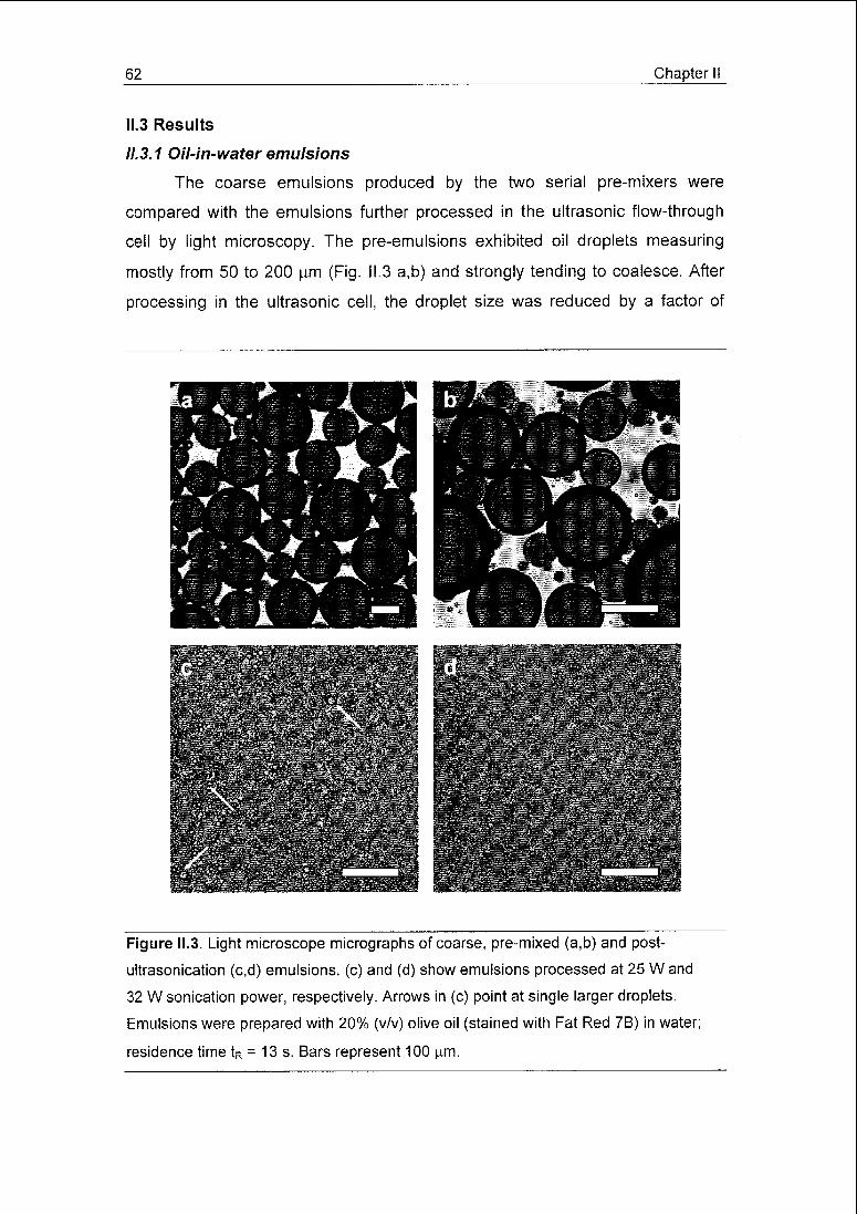
62 Chapter II
11.3 Results
11.3.1 Oil-in-water emulsions
The coarse emulsions produced by the two serial pre-mixers were
compared with the emulsions further processed in the ultrasonic flow-through
cell by light microscopy. The pre-emulsions exhibited oil droplets measuring
mostly from 50 to 200 urn (Fig. II 3 a,b) and strongly tending to coalesce. After
processing in the ultrasonic cell, the droplet size was reduced by a factor of
Figure II.3. Light microscope micrographs of coarse, pre-mixed (a,b) and post-
ultrasonication (c,d) emulsions, (c) and (d) show emulsions processed at 25 W and
32 W sonication power, respectively. Arrows in (c) point at single larger droplets
Emulsions were prepared with 20% (v/v) olive oil (stained with Fat Red 7B) in water;
residence time tR = 13 s. Bars represent 100 urn.
'-fa~
:;:::T^f'.;;^£;/;?iftW :::"

Chapter II 63
approximately 100, yielding mean diameters of less than 1 um (Fig. II.4), While
occasional oil droplets of 5 to 10 urn could be observed in emulsions processed
at an ultrasonic power of 25 W (Fig. II.3 c, arrows), practically no droplets were
microscopically visible at 32 W, i.e. at full power (Fig. II.3 d).
The repeatability of the oil-in-water emulsification at full sonication power
(32 W) was generally good irrespective of the residence time, the oil-to-water
ratio and oil type. As an example, for six batches of olive oil in water emulsions
prepared under identical conditions at maximum power virtually superimposed,
mono-modal distributions were obtained (Fig. II.4).
10 j
0.1 1 10 100
Oil droplet diameter [u,m]
Figure II.4. Droplet size distribution for repeated production of a 20% (v/v) olive oil in
water emulsion. Emulsion production was repeated six times under identical conditions
(tR = 13 s, 32 W sonication power).
When sonication power was decreased from 32 W to 25 W, the Sauter
diameter increased from 0.54 to 0.73 u.m at likewise slightly increased batch-to-
batch variability (Fig. II.5). The larger droplet mean diameter resulted from an
increased span rather than a shift of the size distribution. At 32 W, the 10 and

64 Chapter II
90% percentiles of the droplet size distribution amounted to 0.26 and 1.88 urn
whereas at 25 W values of 0.30 and 3.69 urn were obtained. A further decrease
of the sonication power to 17 W yielded a very inhomogeneous emulsion with a
large number of macroscopically visible droplets of > 1 mm and therefore, this
experiment was not repeated. Sonication below 17 W did not afford proper
emulsification.
10
P [W] D[3,2] [urn]
25 0 73 ±0 05
32 0 54 ± 0 01
o
Ü03
O>
"03
0
0.1 1 10 100
Oil droplet diameter [urn]
Figure II.5. Change of the droplet size distribution of a 20% olive oil in water emulsion
with sonication power- 25 W (---) and 32 W (—). Residence time tR = 25 s. For both
power levels, the resulting emulsion Sauter diameter D[3,2] is given as mean of three
batches ± standard deviation.
The residence time of the emulsions in the ultrasonic flow-through cell
was controlled by proportionally varying the flow rate of both the oil and water.
The oil content of the emulsion was altered by varying the oil flow rate and
keeping the water flow rate constant. Irrespective of the oil content, it was
observed that the mean droplet size decreased with longer residence time of
the emulsion in the sonic field (Fig. II.6, left panel). The droplet size reduction

Chapter II 65
occurred in a degressive manner, i.e. increasingly longer residence times were
required to reduce the mean droplet diameter by a given decrement. For none
of the curves, the diameter could be reduced below that displayed for the
longest respective residence time; a more prolonged sonication did not further
improve results. Therefore, 0.65, 0.50 and 0.47 urn represent the limiting Sauter
diameters achievable for 33, 20 and 11% olive oil-in-water emulsions with the
present ultrasonic flow-through cell. The variability for repeated production was
generally low as reflected by standard deviations of generally below 0.03 urn.
For a fixed residence time, the emulsion mean droplet diameter increased with
the oil content. In agreement with the findings for varied sonication power, the
decrease of the mean droplet size with increasing residence time is caused by a
narrowing span of the size distribution. For an 11% olive oil in water emulsion
15 30 45 60
Residence time tR [s]
10
CT*
c
g'sm
14—
<D
E_5o>
0.1 1 10 100
Oil droplet diameter [urn]
Figure II.6. Left panel: Sauter diameter as a function of the residence time in the
ultrasonic field for 11% (A), 20% () and 33% (v/v) (•) emulsions of olive oil in water.
Error bars are for repeated productions (n = 3). Right panel: Influence of the residence
time on the droplet size distribution of 11% (v/v) olive oil in water emulsions: 28 s (—),
14 s (—) and 7 s (....). Sonication power was set to 32 W for all experiments.
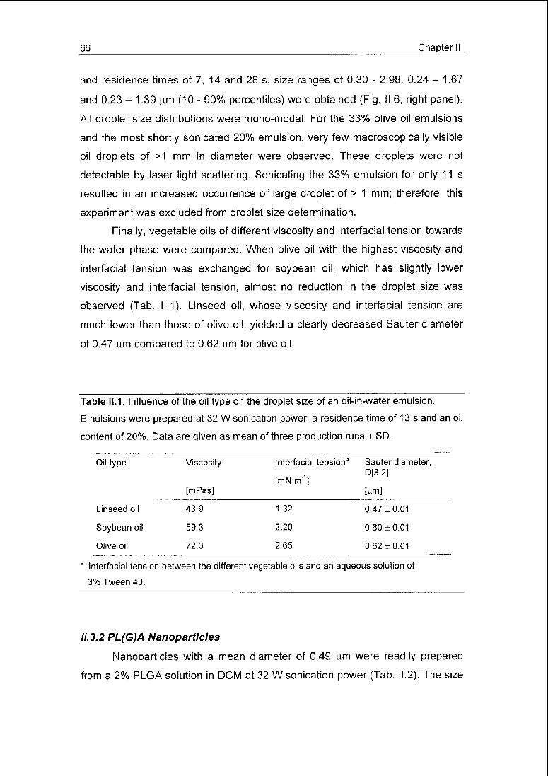
66 Chapter II
and residence times of 7, 14 and 28 s, size ranges of 0.30 - 2.98, 0.24 - 1.67
and 0.23 - 1.39 urn (10 - 90% percentiles) were obtained (Fig. II.6, right panel).
All droplet size distributions were mono-modal. For the 33% olive oil emulsions
and the most shortly sonicated 20% emulsion, very few macroscopically visible
oil droplets of >1 mm in diameter were observed. These droplets were not
detectable by laser light scattering. Sonicating the 33% emulsion for only 11 s
resulted in an increased occurrence of large droplet of > 1 mm; therefore, this
experiment was excluded from droplet size determination.
Finally, vegetable oils of different viscosity and interfacial tension towards
the water phase were compared. When olive oil with the highest viscosity and
interfacial tension was exchanged for soybean oil, which has slightly lower
viscosity and interfacial tension, almost no reduction in the droplet size was
observed (Tab. 11.1). Linseed oil, whose viscosity and interfacial tension are
much lower than those of olive oil, yielded a clearly decreased Sauter diameter
of 0.47 urn compared to 0.62 urn for olive oil.
Table 11.1. Influence of the oil type on the droplet size of an oil-in-water emulsion.
Emulsions were prepared at 32 W sonication power, a residence time of 13 s and an oil
content of 20%. Data are given as mean of three production runs ± SD.
Oil type Viscosity interfacial tension3 Sauter diameter,
r m -i,D[3'2]
[mN m ][mPas] [um]
Linseed oil 43.9 132 0 47 ±0.01
Soybean oil 59 3 2.20 0.60 ±0.01
Olive oil 72.3 2 65 0.62 ±0 01
aInterfacial tension between the different vegetable oils and an aqueous solution of
3% Tween 40
11.3.2 PL(G)A Nanoparticles
Nanoparticles with a mean diameter of 0.49 urn were readily prepared
from a 2% PLGA solution in DCM at 32 W sonication power (Tab. 11.2), The size
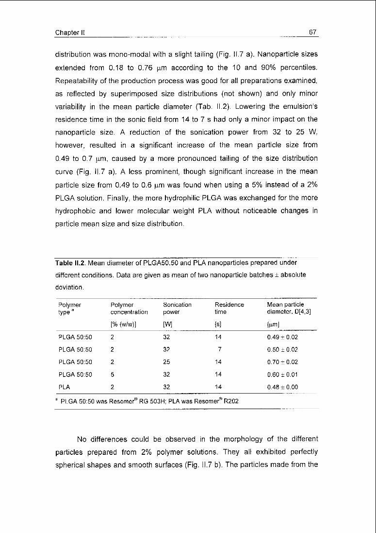
Chapter II 67
distribution was mono-modal with a slight tailing (Fig. 11.7 a). Nanoparticle sizes
extended from 0.18 to 0.76 urn according to the 10 and 90% percentiles.
Repeatability of the production process was good for all preparations examined,
as reflected by superimposed size distributions (not shown) and only minor
variability in the mean particle diameter (Tab. II.2). Lowering the emulsion's
residence time in the sonic field from 14 to 7 s had only a minor impact on the
nanoparticle size. A reduction of the sonication power from 32 to 25 W,
however, resulted in a significant increase of the mean particle size from
0.49 to 0.7 urn, caused by a more pronounced tailing of the size distribution
curve (Fig. II.7 a). A less prominent, though significant increase in the mean
particle size from 0.49 to 0.6 urn was found when using a 5% instead of a 2%
PLGA solution. Finally, the more hydrophilic PLGA was exchanged for the more
hydrophobic and lower molecular weight PLA without noticeable changes in
particle mean size and size distribution.
Table II.2. Mean diameter of PLGA50:50 and PLA nanoparticles prepared under
different conditions. Data are given as mean of two nanoparticle batches ± absolute
deviation.
Polymertype3
Polymerconcentration
Sonication
power
Residence
time
Mean particlediameter, D[4,3]
[% (w/w)] [W] [s] fom]
PLGA 50:50 2 0*£ 14 0.49 ± 0.02
PLGA 50:50 2 32 7 0.50 ±0.02
PLGA 50:50 2 25 14 0.70 ±0.02
PLGA 50:50 5 32 14 0.60 ±0.01
PLA 2 32 14 0.48 ±0.00
a
PLGA 50:50 was Resomer® RG 503H; PLA was Resomer® R202
No differences could be observed in the morphology of the different
particles prepared from 2% polymer solutions. They all exhibited perfectly
spherical shapes and smooth surfaces (Fig. II.7 b). The particles made from the

68 Chapter II
5% PLGA solution, however, were less spherical, showed slightly wrinkly
surfaces, and fusions of two or- less frequently - more particles were observed
(Fig. 11.7 c).
When particles were produced from a 2% PLGA solution using water
saturated in DCM, no difference could be seen in terms of morphology and
particle size compared to particles made using non-saturated water (not
shown).
Figure 11.7. PLGA nanoparticles. (a): Size distribution of particles prepared at a
polymer concentration/ sonication power of 2%/ 32 W (—), 5%/ 32 W (—), and 2%/ 25
W% (....); residence time tR = 14 s. (b),(c): SEM pictures of particles prepared of 2 and
5% polymer solutions, respectively. Residence time tR = 14 s; sonication power was set
to 32 W. Bars represent 1 urn.
Chapter II 69
11.4 Discussion
11.4.1 Working principle of the ultrasonic flow-through cell
The key innovation of the ultrasonic flow-through cell examined in this
study was the transmission of sonic waves from an ultrasound emitting source
(sonotrode) to the liquid mixture to be emulsified via a pressurised transmission
fluid. The transmission fluid surrounded a glass tube through which the
emulsion flowed. Using this set-up, direct contact between the sonotrode and
the emulsion was prevented, avoiding contamination of the emulsion with ions
or particles eroded from the metallic sonotrode by cavitation. Furthermore, as
the glass tube is the only part of the ultrasonic cell coming into contact with the
emulsion, cleaning and aseptic production is facilitated. Prior to production, the
tube can be sterilised by any suitable means and easily installed into the cell
under aseptic conditions. At the end of production, the tube can be removed
from the cell and either cleaned or exchanged for a new one.
Cavitation is a well described phenomenon in the interaction of high-
intensity ultrasound with liquids [16]. Very briefly, above a specific sound
intensity, microbubbles form in the liquid during the low-pressure phase of the
sonic oscillation. After oscillating for several pressure cycles accompanied by
an overall bubble growth, these microbubbles will collapse resulting in a shock
wave with local pressure and temperature of up to 1000 bar and several
thousand Kelvin [16]. However, when a liquid is pressurised above a specific
pressure threshold, which depends on temperature and the physicochemical
characteristics of the fluid, cavitation will not occur. For the experiments
accomplished in this study, pressures of above 4.5 bar were found to be
sufficient to suppress cavitation in the transmitting water. Thus, acoustic energy
was efficiently transferred via the glass tube into the emulsion. As the latter was
not pressurized, cavitation occurred, resulting in break-up of the oil droplets.
Ultrasonic emulsification was described as a two-step process [17,18],
First, instable interfacial waves form at the oil-water interface, which results in
the eruption of rather large oil droplets (approx. 50 - 100 urn) into the water
phase. Second, the shock waves of cavitation events in the close vicinity of the
coarse oil droplets will cause their disruption into much finer droplets. In viscous
fluids, the formation of instable interfacial waves is compromised. Thus, a pre-
70 Chapter II
mixing step producing a coarse emulsion, which can be readily broken up
further by cavitation, is beneficial for such substances. In our experiments with
the ultrasonic flow-through cell, emulsions of vegetable oils in water could not
be prepared without pre-mixing. Pre-mixing is indeed crucial when using the
flow-through cell, as compared to a sonotrode-beaker set-up, as the latter will
provide streaming and, thus, macroscopic mixing which does not occur in the
flow-through cell.
11.4.2 Oil-in-water emulsions
Optical micrographs of the emulsions prepared at 25 and 32 W power
output (Fig. 11.3 c,d) mirrored well the droplet size distributions obtained by laser
light scattering (Fig. 11.5). Larger droplets of 5 to 10 um were observed
microscopically and by light scattering analysis for the emulsions prepared at
25 W sonication power, but not for the preparation treated with 32 W.
The emulsion droplet mean size decreased both with increasing
sonication power and residence time, in agreement with findings in the literature
[6,7,19], Both measures increase the energy transferred to the emulsion by
enhancing the absolute number and, for increased power, also the intensity of
the cavitation events, resulting in a more effective droplet size reduction.
However, an optimal power input exists above which coalescence will become
predominant resulting in a re-increase of the droplet mean diameter [16]. The
narrowing of the droplet size distribution observed with both increased
sonication power and residence time results from the susceptibility of larger
droplets to be broken up by cavitation, while smaller droplets are more resistant
or even stable. Enhancing the number of cavitation events by either increased
power or residence time predominantly affects larger oil droplets and leads to
an accumulation of fine droplets (given that coalescence is comparatively slow).
An increased oil content in the emulsion yielded, at fixed sonication
power and residence time, larger oil droplets, which is agreement with earlier
studies [7]. As cavitation occurs predominantly in the continuous aqueous
phase [16], a larger fraction of oil requires more cavitation events per unit
volume emulsion. Therefore, more concentrated oil-in-water emulsions require
longer residence time to yield a desired mean droplet size. Nonetheless, the
Chapter II 71
limiting droplet diameter increased with the oil content even under prolonged
sonication. This is probably due to intensified coalescence in the concentrated
emulsions as well as to changes in the sound conduction and cavitation
properties of the liquid mixture. Moreover, higher oil contents would possibly
have required increasing amounts of surfactant for stabilisation.
In emulsions with high oil content, few macroscopically visible oil droplets
survived the sonication process. As these droplets were considerably larger
than those produced by the pre-mixer, they must have formed by accumulation
and coalescence of coarse pre-emulsion droplets in the inlet tube or the nodes
of the ultrasonic cell. Repeatedly passing the emulsion a second or more times
through the cell abolished this problem.
When different vegetable oils were compared, as could be expected from
literature [6,16], the least viscous linseed oil yielded a reduced Sauter diameter.
The break-up of low viscosity droplets will require less vigorous cavitation shock
waves than needed for more viscous ones, promoting break-up. However, a
decrease in the emulsion droplet mean diameter was not observed when olive
oil was exchanged for soybean oil, which has an intermediate viscosity. While
the interfacial tension between the aqueous surfactant solution and the olive
(2.65 ± 0.23 mN/m) and soybean oils (2.20 ±0.18 mN/m) was found to be
similar, that of linseed oil, however, was significantly lower (1.32 + 0.20 mN/m).
Thus, for linseed oil, reduced interfacial tension and viscosity may have added
to result in simplified droplet disruption, while for soybean oil these parameters
were not sufficiently different from those of olive oil to exert a significant effect.
The energy density, i.e. the energy input per unit volume of emulsion,
was estimated from the power dissipated per unit volume of emulsion divided by
the emulsion flow rate. In the production of a 20% vegetable oil-in-water
emulsion, energy densities of around 108 Jm"3 were required to yield Sauter
diameters of approximately 0.4 - 0.5 urn [19]. For the ultrasonic flow-through cell
examined here, the power consumption of the high frequency generator was
measured instead of the power dissipated in the emulsion. An energy
consumption of approx. 109 J m"3 was found to yield a Sauter diameter of
0.5 p.m. Relating this energy consumption with that required for emulsification,
an energetic efficiency of approx. 10% was obtained. Therefore, the energy

72 Chapter II
transfer in the flow through cell is less efficient than in a classical system of a
sonotrode installed in a beaker (26% - 75%) [13,14]. The lower efficiency of the
ultrasonic cell could be expected from the more complex mechanism of energy
transfer. In the beaker set-up, the sound emitting sonotrode is in direct contact
with the emulsion, while in the flow-through cell, the sonotrode excites the steel
jacket, which in turn transfers the energy to the pressurised water and the glass
tube, which then finally excites the emulsion. Moreover, the mode of excitation
is different in both systems. In the beaker system, the sonotrode basically
performs a longitudinal vibration, whereas the steel jacket of the flow-through
cell transforms the longitudinal oscillation of the attached sonotrode into a
transversal oscillation. Finally, as the volume sonicated in the present cell is
very small (0.53 ml), the energy expended for exciting the apparatus itself
largely outweighs the energy expended for emulsification. With slightly to
moderately larger diameter glass tubes or a manifold of parallel small tubes
installed in the cell's steel jacket, the sonicated volume would increase,
probably without much impact on the overall energy consumption.
11.4.3 PL(G)A nanoparticles
Solvent extraction/evaporation employing ultrasonic emulsification is a
common process for the preparation of biodegradable PLA/PLGA micro- and
nanoparticles [15,20]. Briefly, it consists of forming an emulsion of an organic
solution of the polymer in usually an aqueous continuous extraction phase. A
drug to be encapsulated may be co-dissolved or dispersed in the polymer
solution. The organic solvent is then either extracted by the continuous phase
(solvent extraction), diffuses into the same and evaporates to the environment
(solvent evaporation), or is removed by a combination of both. The size of the
resulting particles is mainly determined by the emulsification conditions, but
other factors like polymer concentration, viscosity, the ratio of dispersed to
continuous phase do also play a role. Although ultrasound is frequently used to
generate emulsions for nanoparticle preparation, high-pressure homogenisation
or rotor-stator dispersion are equally employed.
In the present study, we demonstrate the feasibility of nanoparticle
preparation in the ultrasonic flow-through cell, opening the road to nanoparticle
Chapter II 73
production under aseptic conditions. For PLA/PLGA nanoparticles, emulsion
formation in the ultrasonic flow-through cell was fast, as the reduction of the
residence time from 14 to 7 s did not markedly increase the particle diameter. In
analogy to the oil-in-water emulsions, particle sizes increased at decreased
sonication power, though the differences in size distribution were less
pronounced than observed for the oil emulsions. By increasing the polymer
solution concentration, and thereby its viscosity, larger particles were produced.
Interestingly, no impact on the particle size was observed when PLGA was
substituted by PLA having roughly half the inherent viscosity, while in the
literature a correlation between polymer inherent viscosity and nanoparticles
size was reported [15]. Obviously, viscosity is not the only physicochemical
parameter governing emulsification, as already noted for the oil-in-water
emulsions. Factors like interfacial tension and suitability of the employed
surfactants are equally important, especially with respect to droplet
coalescence.
The deformed and partially fused nanoparticles observed for the 5%
PLGA solution probably resulted from rapid solvent deprivation and particle
solidification, reducing the time available for droplet break-up (larger and fused
particles) and shape rearrangement.
II.5 Conclusions
In the present study, a novel technology for the continuous treatment of
fluid mixtures with ultrasound was characterised using vegetable oil-in-water
emulsions as a model system. The flow-through equipment consisted of a glass
tube for the conduction of the sonicated fluid, which was installed in a steel
jacket excited by a transducer and filled with pressurised water for the
transmission of the sound waves. Its design makes this apparatus well suited
for aseptic processing, an important issue in pharmaceutical development and
production. The mean droplet diameter of oil-in-water emulsions could be
decreased by two orders of magnitude starting from coarse pre-emulsions and
yielding Sauter diameters of 0.5 urn and below. The reduced efficiency of sound
energy transfer compared to directly contacting sonotrode and fluid might be

74 Chapter II
improved by scaling-up the cell. Furthermore, the ultrasonic flow-through cell
was found to be well suited for emulsion-solvent extraction/evaporation based
production of biodegradable polymeric nanoparticles. Future research will be
directed towards scaling-up the process and increasing the power input to yield
even finer emulsions. In addition, the suitability of the cell for the preparation of
water-in-oil emulsions, e.g. for further processing into drug-loaded
microspheres, will be studied.
Acknowledgements
The authors would like to thank Dr. Ernst Wehrli, Laboratory of Electron
Microscopy, ETH Zürich for the preparation of the scanning electron
micrographs.
References
[1] H. Karbstein, H. Schubert, Developments in the continuous mechanical
production of oil-in-water macro-emulsions, Chem. Eng. Process, 34
(1995)205-211.
[2] W.T. Richards, The chemical effects of high frequency sound waves: II.
A study of emulsification action, J. Am. Chem. Soc. 51 (1929) 1724-
1729.
[3] C. Bondy, K. Sollner, On the mechanism of emulsification by ultrasonic
waves, Trans. Faraday Soc. 31 (1935) 835-842.
[4] S. Bechtel, S. Kielhorn-Bayer, K. Mathauer, Vorrichtung zum Herstellen
von dispersen Stoffgemischen mittels Ultraschall und Verwendung einer
derartigen Vorrichtung, German Patent 197 56 874, 1997.
[5] J. Medina, A. Salvadö, A. del Pozo, Use of ultrasound to prepare lipid
emulsions of lorazepam for intravenous injection, Int. J. Pharm. 216
(2001) 1-8.
[6] Y.F. Maa, C.C. Hsu, Performance of sonication and microfluidization for
liquid-liquid emulsification, Pharm. Dev. Technol. 4 (1999) 233-240.

Chapter II 75
[7] B. Abismaïl, J.P. Canselier, A.M. Wilhelm, H. Delmas, C. Gourdon,
Emulsification by ultrasound: drop size distribution and stability, Ultrason.
Sonochem. 6 (1999) 75-83.
[8] H. Hielscher, Flow vessel for a disintegrator, UK Patent Application
2,250,930, 1991.
[9] G. Pöschl, Schallwandler, German Patent 39 30 052, 1989.
[10] S. Freitas, A. Walz, H.P. Merkle, B. Gander, Solvent extraction
employing a static micromixer: a simple, robust and versatile technology
for the microencapsulation of proteins, J. Microencapsulation, 20 (2003)
67-85.
[11] S. Freitas, H.P. Merkle, B. Gander, Ultrasonic atomisation into reduced
pressure atmosphere - envisaging aseptic spray-drying for
microencapsulation, J. Control. Release, in press.
[12] S. Freitas, B. Gander, N. Lehmann, Verfahren und Durchflusszelle zur
kontinuierlichen Bearbeitung von fliessfähigen Zusammensetzungen
mittels Ultraschall, German Patent Application 102 43 837, 2002.
[13] Ratoarinoro, F. Contamine, A.M. Wilhelm, J. Berian, H. Delmas, Power
measurement in sonochemistry, Ultrason. Sonochem. 2 (1995) S43-S47.
[14] J.M. Löning, C. Horst, U. Hoffmann, Investigations on the energy
conversion in sonochemical processes, Ultrason. Sonochem. 9 (2002)
169-179.
[15] V. Hoffart, N. Ubrich, C. Simonin, V. Babak, C. Vigneron, M. Hoffman, T.
Lecompte, P. Maincent, Low molecular weight heparin-loaded polymeric
nanoparticles: formulation, characterization and release characteristics,
Drug Dev. Ind. Pharm. 28 (2002) 1091-1099.
[16] J.P. Canselier, H. Delmas, A.M. Wilhelm, B. Abismaïl, Ultrasound
emulsification - an overview, J. Disper. Sei. Technol. 23 (2002) 333-349.
[17] M.K. Li, H.S. Fogler, Acoustic emulsification. Part I. The instability of oil-
water interface to form the initial droplets, J. Fluid Mech. 88 (1978) 499-
511.
76 Chapter II
[18] M.K. Li, H.S. Fogler, Acoustic emulsification. Part II. Breakup of the
primary oil droplets in a water medium, J. Fluid Mech. 88 (1978) 513-
528.
[19] O. Behrend, H. Schubert, Influence of hydrostatic pressure and gas
content on continuous ultrasound emulsification, Ultrason. Sonochem. 8
(2001)271-276.
[20] U. Bilati, E. Allemann, E. Doelker, Sonication parameters for the
preparation of biodegradable nanocapsules of controlled size by the
double emulsion method, Pharm. Dev. Technol. 8 (2003) 1-9.
Chapter III 77
Chapter
Solvent extraction employing a static micromixer: a simple, robust and
versatile technology for the microencapsulation of proteins
Sergio Freitas, Anke Walz, Hans P. Merkle, and Bruno Gander
a
Department of Chemistry and Applied Biosciences, Institute of Pharmaceutical Sci¬
ences, Swiss Federal Institute of Technology Zürich, ETH Hönggerberg HCl,
8093 Zürich, Switzerland
Journal of Microencapsulation, 20 (2003) 67-85

78 Chapter III
111.1 Introduction
With an increasing number of proteins emerging as therapeutic agents,
protein delivery has become a central topic in pharmaceutics. As many of those
proteins are rapidly degraded in the gastro-intestinal tract or cannot pass the
intestinal epithelia, their parenteral delivery is preferred over oral administration.
Due to their short in vivo half-life, repeated injections or intravenous infusion are
often required to achieve sufficiently high plasma levels [1]. Parenteral drug de¬
livery systems providing sustained release as well as protection of the non-
released protein from degradation are therefore advantageous. Microspheres
consisting of the biodegradable polymers poly(lactic acid), PLA, and poly(lactic-
co-glycolic acid), PLGA, have been shown to provide these characteristics [2]
while degrading to toxicologically acceptable products.
The most common technologies for the preparation of drug-loaded mi¬
crospheres are solvent extraction or evaporation, coacervation and spray-drying
[3]. Solvent extraction/evaporation is the most frequently used method for the
encapsulation of proteins into PLA/PLGA microspheres (e.g. [2, 4-7]) due to its
mild processing conditions and the use of comparatively safe processing
agents. A critical step during the process is the formation of a W/O/W double
emulsion when a pre-formed dispersion of an aqueous protein solution in an or¬
ganic polymer solution (W/O) is emulsified in a second aqueous solution (re¬
ferred to as the extraction fluid). The commonly employed lab bench procedure
for this second emulsification step consists of two sub-steps: Firstly, the addition
of the pre-formed protein/polymer dispersion (W/O) into a small amount of ex¬
traction fluid under vigorous agitation using a magnetic, propeller or turbine stir¬
rer to form a double emulsion (W/O/W); secondly, the addition of a large
amount of extraction fluid under gentle stirring to harden the microdroplets and
form the microspheres. This technique encompasses a number of drawbacks.
Process scale-up is difficult and may impose a lengthy trial-and-error approach
to adjust the hydrodynamic conditions of larger reactors to the desired micro¬
sphere size distribution. While suitable mean diameters may be readily
achieved at reasonable effort [8], control over the distribution's profile may be
more difficult to achieve, but is crucial for the release kinetics of the entrapped
protein and the in vivo fate of the microspheres. Equally challenging is the ad-

Chapter III 79
justment of the hydrodynamics in the production vessel when changes in poly¬
mer concentration, polymer type or polymer solvent are needed. Moreover, sol¬
vent extraction/evaporation is typically a batch process and therefore difficult to
automate. However, for aseptic production of protein-loaded microspheres at
large scale an automated process would be a must.
A number of approaches were previously proposed for improved control
of microsphere size distribution and to allow for continuous production. Static
mixers installed in tubes [9] feature continuous production, but fail to offer much
improved microsphere size distribution control as compared to conventional
stirred tank reactors. However, formation of single droplets of the pro¬
tein/polymer dispersion by extrusion through, e.g., needles, orifices, mem¬
branes or channels and their simultaneous or subsequent exposure to the ex¬
traction fluid seem to be more advantageous over systems relying on bulk mix¬
ing. As bulk mixing depends on chaotic turbulent flow patterns for disruption of
the protein/polymer dispersion into droplets it is difficult to obtain well controlla¬
ble and narrow size distributions. In this context, a quasi-continuous process
was proposed featuring the drug/polymer solution to be fed by a needle into a
co-current stream of extraction fluid [10]. In a similar approach, a stream of ex¬
traction fluid flowing perpendicularly to the needle was employed [11]. Further¬
more, an electrostatic field was applied to form microdroplets of a pro¬
tein/polymer dispersion when fed through a needle [12], However, none of
these approaches proved able to produce microspheres with mean diameters of
less than approximately 70 u.m and very broad size distributions were found.
Further, microporous glass membranes were used to extrude a polymer solu¬
tion into an extraction fluid [13]. The produced microspheres were nearly mono-
disperse with their mean size varying between 1 and 3 urn, depending on the
pore size of the microporous membrane. Recently, a promising but rather com¬
plex technology was developed using a jet of polymer solution which was
pumped through a fine orifice, disrupted by vibration to equally sized droplets
and subsequently collected in an extraction fluid [14]. Spheres of monomodal
distribution with adjustable sizes in the range of 25 to 500 urn could be pro¬
duced. The size of the microspheres was further decreased when the polymer
solution jet was additionally surrounded by an annular mantle of a downward

80 Chapter III
carrier fluid stream to accelerate and thin the jet by fractional forces. As a result,
microspheres as small as 1 u.m with monomodal distribution were obtained.
Here, a new technology is introduced to prepare microspheres by means
of a static micromixer. The micromixer was previously used for the dispersion of
immiscible fluids [15], to produce pharmaceutical creams [16], as chemical re¬
actor [17] and for fluid extraction [18], It is small-sized, features a simple set-up,
lacks moving parts, can be run continuously and is easy to sterilise. Thus, the
micromixer is ideally suited for automation and aseptic manufacturing. Further¬
more, it offers good size distribution control and tolerates a wide range of ingre¬
dients and excipients. Scale-up from the laboratory bench to the industrial plant
is feasible simply through the parallel installation of a sufficient number of indi¬
vidual units ("number-up"). Thus, by multiplication of units, laboratory bench and
large-scale production can be made on the same micromixer, with considerable
advantages for development and registration, and the adaptation to different
batch sizes can be made by simply adding or removing mixing units.
The scope of this work was to evaluate the potential of the static mi¬
cromixer for the microencapsulation of a model protein, bovine serum albumin
(BSA), in PLGA microspheres by solvent extraction. For this purpose the effect
of various process and formulation parameters on the characteristics of the re¬
sulting microspheres was studied with a special focus on particle size distribu¬
tion.
III.2 Materials and methods
111,2.1 Materials
Various poly(lactic-co-glycolic acid) type polymers (Resomer® RG502H,
RG503, RG503H and RG752) were obtained from Boehringer-lngelheim (Ingel¬
heim, Germany). The physico-chemical properties of the polymers are detailed
in the results section. Bovine serum albumin (BSA, fraction V) was from Fluka
(Buchs, Switzerland). Poly(vinylalcohol) (PVA, Mowiol® 4-88) and poly-
sorbate 20 were from Hoechst (Frankfurt/M., Germany) and Hänseier (Herisau,
Switzerland), respectively. Dichloromethane (DCM) and ethyl formate (EF) were

Chapter III 81
of synthesis grade and obtained from EGT Chemie (Scharlau, Switzerland) and
Fluka, respectively.
III.2.2 Experimental set-up
The experimental set-up used to prepare the microspheres consisted of
two HPLC piston pumps (L-6000, Hitachi-Merck, Darmstadt, Germany;
10 ml/min maximum flow) connected in parallel to a T-type valve to sum up their
flow capacities, a syringe pump (KDS100, kdScientific, New Hope, USA), the
static micromixer (featuring two exchangeable mixing tools with channel widths
of 25 and 40um, both made of silver on a copper support), that was purchased
from the Institut für Mikrotechnik Mainz (IMM), Mainz, Germany, and equipped
with a stainless steel outlet tube of 120 mm length and a standard glass beaker
(Fig. 111.1). By means of the piston pumps the extraction fluid was fed into one of
the two inlets of the micromixer, while the previously prepared protein/polymer
dispersion was fed into the other inlet by means of the syringe pump. Upon con¬
tact between the protein/polymer dispersion and the extraction fluid nascent mi¬
crospheres were formed inside the micromixer. For final hardening and product
collection the resulting dispersion was transferred into the beaker containing
150 ml extraction fluid.
HPLC piston pumps
micromixer
pre-formedprotein/polymer dispersion
extraction fluid
additional
extraction fluid
magnetic stirrer
Figure 111.1. Experimental set-up for the production of BSA-loaded microspheres by
solvent extraction employing a micromixer.

82 Chapter III
111.2.3 Preparation of the microspheres
Solutions of BSA in PBS (pH = 7.4) and of PLGA in EF or DCM were
prepared at various concentrations. BSA solution was added to 3-4 ml of poly¬
mer solution at specific ratios R (given as mg BSA solution per mg polymer so¬
lution) and finely dispersed for about 15 s at 50 W using a 20 kHz, 6 mm ultra¬
sound probe (VibraCell VC50T, sonics and materials, Danbury, USA). The
nominal drug load of the microspheres to be prepared, LD, i.e. the nominal
amount of drug entrapped in the particles, mD, divided by the amount of polymer
employed, mp, was calculated by:
Ld=^ = r.^h (1)mP wp
where wD and wP denote the weight fraction of the drug and the polymer in their
respective solutions.
The protein/polymer dispersion was transferred into a 20 ml single-use
syringe (Discardit II, Becton-Dickinson, Basel, Switzerland), which was installed
in the syringe pump. Aqueous PVA and polysorbate 20 solutions (0.5% w/w
each) were used as extraction fluids. After micromixing and collection in the
glass beaker, the particles were allowed to harden in the extraction fluid under
gentle stirring and at room temperature, either for 30 min (EF) or 90 min (DCM).
The product was harvested by filtration over a 0.2 u.m pore cellulose acetate fil¬
ter (Sartorius, Göttingen, Germany), washed twice with 150 ml of deionised wa¬
ter, and finally dried for 24 h at 20 mbar and room temperature. All experiments
were conducted in an air-conditioned room at 20 °C.
111.2.4 Particle size distribution
Samples of approximately 30 mg of dried microspheres were dispersed
in 12 ml of de-ionised water and subsequently treated with ultrasound for 5 s
(VibraCell VC50T, sonics and materials, Danbury, USA; 50 W, 20 kHz, 6 mm
probe). Microsphere size was determined by laser light scattering (Master-
sizer X, Malvern, Worcestershire, UK, equipped with a 100 mm lens) using a
Fraunhofer diffraction model for the analysis of the raw data. All size distribu¬
tions are presented in the volume-weighted mode and characterised by their 10,
50 and 90% undersize diameters d(v,0.1), d(v,0.5) and d(v,0.9). The 50% un-

Chapter III 83
dersize diameter is referred to as the mean diameter, and d(v,0.1) and d(v,0.9)
are used to characterise the span of the distribution.
111.2.5 Encapsulation efficiency
Samples of approximately 40 mg of dried microspheres were dissolved in
4 ml of DCM, and BSA was separated from the dissolved polymer by filtration
over a 0.2 urn-pore regenerated cellulose filter (Sartorius, Göttingen, Germany).
The filter was washed once with 6 ml of DCM to remove remaining polymer.
BSA was then extracted from the filter into 10 ml of PBS by shaking for 3 h. The
resulting solution was diluted to 25 ml and analysed fluorimetrically (Cary
Eclipse, Varian, Mulgrave, Australia) at an excitation wavelength of 278 nm and
an emission wavelength of 347 nm. The encapsulation efficiency s was ex¬
pressed as the ratio of the amount of BSA extracted from the microspheres to
the amount of BSA employed for the preparation of the spheres. This protocol
was validated for accuracy. Typical deviations observed for repeated analysis
were below 1% of the averaged encapsulation efficiency.
111.2.6 In vitro burst release
The release of BSA from the microspheres was determined using ap¬
proximately 20 mg of dried microspheres in 4.5 ml glass vials containing 4 ml
PBS and placed in an overhead mixer (Heidolph Reax 2, Heidolph, Schwabach,
Germany) revolving at 60 rpm and incubated at 37 °C. For complete dispersion
of the microspheres prior to the experiment the vials were shaken vigorously for
a few seconds. At predefined time points, the vials were centrifuged at
3700 rpm for 5 min (sigma 204, Sigma, Osterode/Harz, Germany), and 1.5 ml of
the clear supernatant was taken for fluorimetric assay and replaced by fresh
PBS. The amount of BSA released was expressed as fraction of the experimen¬
tally determined total BSA content.
111.2.7 Scanning electron microscopy (SEM)
Samples of dried microspheres were placed on a double-sided adhesive
tape and coated with 6 nm of platinum using a planar magnetron sputter-coater
(MED 010, Bal-Tec, Balzers, Liechtenstein). The micrographs were taken on a
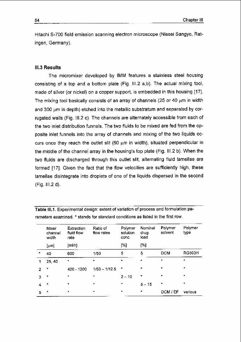
84 Chapter III
Hitachi S-700 field emission scanning electron microscope (Nissei Sangyo, Rat-
ingen, Germany).
III.3 Results
The micromixer developed by IMM features a stainless steel housing
consisting of a top and a bottom plate (Fig. III.2 a,b). The actual mixing tool,
made of silver (or nickel) on a copper support, is embedded in this housing [17].
The mixing tool basically consists of an array of channels (25 or 40 u,m in width
and 300 u,m in depth) etched into the metallic substratum and separated by cor¬
rugated walls (Fig. III.2 c). The channels are alternately accessible from each of
the two inlet distribution funnels. The two fluids to be mixed are fed from the op¬
posite inlet funnels into the array of channels and mixing of the two liquids oc¬
curs once they reach the outlet slit (60 urn in width), situated perpendicular in
the middle of the channel array in the housing's top plate (Fig. III.2 b). When the
two fluids are discharged through this outlet slit, alternating fluid lamellae are
formed [17]. Given the fact that the flow velocities are sufficiently high, these
lamellae disintegrate into droplets of one of the liquids dispersed in the second
(Fig. Ill.2d).
Table 111.1. Experimental design: extent of variation of process and formulation pa¬
rameters examined. * stands for standard conditions as listed in the first row.
Mixer
channel
width
[nm]
Extraction
fluid flow
rate
[ml/h]
Ratio of
flow rates
Polymersolution
cone.
[%]
Nominal
drugload
[%]
Polymersolvent
Polymertype
* 40 600 1/50 5 5 DCM RG503H
1 25,40* * * * *
2* 420-1200 1/50-1/12.5
*
3* * * 2-10
* * *
4* * * * 5 — 15*
*
5 * * * DCM/EF various
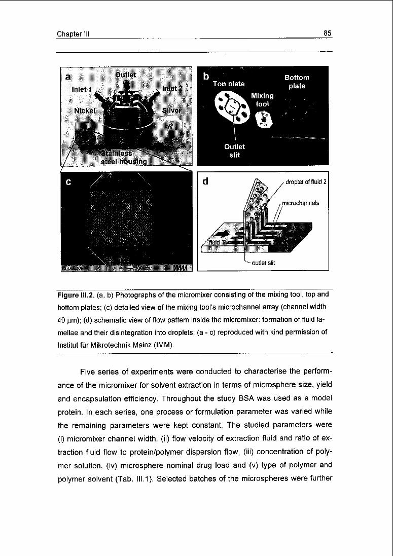
Chapter III 85
Figure 111.2. (a, b) Photographs of the micromixer consisting of the mixing tool, top and
bottom plates; (c) detailed view of the mixing tool's microchannel array (channel width
40 pm); (d) schematic view of flow pattern inside the micromixer: formation of fluid la¬
mellae and their disintegration into droplets; (a - c) reproduced with kind permission of
Institut für Mikrotechnik Mainz (IMM).
Five series of experiments were conducted to characterise the perform¬
ance of the micromixer for solvent extraction in terms of microsphere size, yield
and encapsulation efficiency. Throughout the study BSA was used as a model
protein. In each series, one process or formulation parameter was varied while
the remaining parameters were kept constant. The studied parameters were
(i) micromixer channel width, (ii) flow velocity of extraction fluid and ratio of ex¬
traction fluid flow to protein/polymer dispersion flow, (iii) concentration of poly¬
mer solution, (iv) microsphere nominal drug load and (v) type of polymer and
polymer solvent (Tab. 111.1). Selected batches of the microspheres were further

86 Chapter III
examined with respect to the in vitro release of BSA and the morphology of the
microspheres.
111,3.1 Repeatability of the microsphere preparation and influence of mi¬
cromixer channel width
Three batches of microspheres were produced using the mixing tool with
40 urn wide channels (Fig. III.3 a,b) and four batches using the tool of 25 urn
channel width (Fig. III.3 c), keeping all other parameters unchanged. In es¬
sence, all resulting particle size distributions exhibited a practically monomodal
shape, with a small fraction of very fine particles (0.5 - 3 urn) in all batches.
For the three batches prepared with the 40 urn tool, the size distributions
of the microspheres were practically identical when measured before filtration
and drying (Fig. III.3 a). After drying, one of the three samples exhibited a mar¬
ginal increase in particle size (Fig. III.3 b, solid line), indicating a tendency of the
spheres to slightly aggregate upon filtration or drying. Possibly for the same
reason, a very small fraction of larger particles (> 100 urn) was observed among
the dried spheres. Nevertheless, for the rest of the study all size distributions
were determined with dried microspheres only. According to the d(v,0.1) and
d(v,0.9) diameters, typically, 80% of the volume weighted particle diameters of
the three batches ranged from 7 to 36 urn. This size range was confirmed by
SEM (Fig. III.8 a). The mean diameters of the two batches unaffected by drying
were almost identical (16.1 and 16.2 urn), whereas that of the mentioned third
batch was slightly larger (18.3 (im). The product yield of the three batches was
high and reproducible, ranging from 93.6 to 95.3%. The encapsulation efficiency
of BSA amounted to 75.9 ± 4.8%.
Using the 25 urn tool, the reproducibility of particle size distribution was
less satisfactory than with the 40 urn tool (Fig. III.3 c). Two out of the four
batches exhibited size distributions similar to those obtained using the 40 um
tool, with mean diameters of 16.0 - 17.0 urn, d(v,0.1) of 7.5 and d(v,0.9) of
35.5 urn. The other two batches, however, featured slightly smaller mean di¬
ameters (13.5 and 14.0 urn) and a narrower distribution (d(v,0.1) = 6.5 and

Chapter III 87
0.1 1 10 100 10 100
o
'£>jo
E
"ö>
Particle diameter (urn)
Figure III.3. Reproducibility of microsphere size distributions, (a) channel width of 40
um, particle size before filtration and drying; (b) channel width of 40 pm, size of dried
particles; (c) channel width of 25 urn, size of dried particles. All other preparation condi¬
tions were identical to Table 111.1 standard conditions.

88 Chapter III
d(v,0.9) - 24.4 urn). This discrepancy was found for both the non-dried and
dried microspheres and, thus, cannot be attributed to agglomeration upon dry¬
ing. Microsphere yields in all four cases were close to 95% as also found with
the 40 urn tool. Encapsulation efficiency was slightly higher but at moderately
increased variability (79.0 ± 7.6%).
111,3.2 Influence of extraction fluid flow rate and flow rate ratio
As described elsewhere [15], the droplet size formed by the micromixer
can be controlled by the flow velocities of the two fluids pumped into the mixer.
In a first series of experiments, the flow rate of the extraction fluid was varied
from 420 to 1200 ml/h (Fig. III.4), while maintaining a 1/50 ratio O of the flow
rates between the protein/polymer dispersion and the extraction fluid. When in¬
creasing the extraction fluid flow rate in the mentioned range, the mean diame¬
ter of the microspheres was decreased from 29.0 to 8.8 urn. The lowering of the
mean diameter was degressive, i.e. increasingly larger extraction fluid flow rates
were required to reduce the mean diameter by a given decrement. The shape of
the size distribution was unaffected by the decrease in the distribution's mean
diameter and, therefore, both d(v,0.1) and d(v,0.9) were shifted in parallel to the
mean diameter. For example, for the lowest (F = 420 ml/h) and highest
(F = 1200 ml/h) extraction fluid flow rate, the particle size range d(v,0.1) to
d(v,0.9) was 14.9 - 50.2 urn and 3.5 - 17.1 urn, respectively. Again, a small
fraction of fine particles was observed in all preparations. Interestingly, both the
microsphere yield (91.2 - 96.4%) and the encapsulation efficiency
(75.1 ± 1.7%) remained essentially unaffected by F (Fig. III.4).
In a second series of experiments, the influence of the ratio O of the pro¬
tein/polymer dispersion flow rate to that of the extraction fluid on the micro¬
spheres' properties was examined (Tab. III.2). The extraction fluid flow rate was
kept at 600 ml/h, while that of the protein/polymer dispersion was adapted to
achieve O-values of 1/50, 1/25 and 1/12.5. Principally, an increase in 0> would
improve the productivity as the output of microspheres per unit mass extraction
fluid and, thus, per time would be raised. An increase in O from 1/50 to 1/12.5
augmented slightly the microspheres' mean diameter from 18.4 to 23.5 p.m.

Chapter III 89
Yield (102.9 ± 1.0%) and encapsulation efficiency (74.5 ± 0.9%) were inde¬
pendent from the flow rate ratio <&.
20
c
g
CO
E
o>
Hc
10
0.1 1 10 100
Particle diameter (urn)
100
w
300 600 900 1200 1500
F (ml/h)
Figure 111.4. Microsphere characteristics as a function of the extraction fluid flow rate F.
Upper panel: particle size distributions obtained at F = 1200, 900, 600, 420 ml/h (from
left to right). Lower panel: microsphere mean diameter, d(v,0.5) (), encapsulation effi¬
ciency, e ().

90 Chapter III
Table III.2. Influence of the ratio between the protein/polymer dispersion flow rate and
extraction fluid flow rate on the characteristics of the microspheres. The extraction fluid
flow rate F was kept at 600 ml/h.
Ratio of flow rates Microsphere mean Yield Encapsulation effi-
diameter ciency
d(v,0.5)
[nm] [%] [%]
1/50 18.4 103.8 73.5
1/25 19.5 101.9 74.8
1/12.5 23.5 103.0 75.3
111.3.3 Influence ofpolymer concentration
Batches of microspheres were produced at various polymer solution con¬
centrations, wp, from 2 to 10% (w/w) (Fig. III.5). The W/O dispersion ratio R was
adapted as to yield a nominal drug load Ld of 5%, constantly using a 5% (w/w)
BSA solution (equation 1). Here, the microspheres' mean diameter varied ran¬
domly between 17.1 and 21.1 urn and the shapes of the size distribution curves
were almost superimposed, with d(v,0.1) = 8.2 ± 1.0 urn and d(v, 0.9) =
37.8 ± 4.4 p.m. Yields were 95.6% on the average and varied considerably
(± 7.2%). BSA encapsulation efficiency tended to increase from approximately
65 to 80% for the range of polymer concentrations examined (Fig. III.5). Never¬
theless, because the deviations from the trendline were found to be quite large
in case of the 2% and 4% solutions, this trend is speculative.
111.3.4 Influence of nominal drug load
Microspheres with nominal BSA loads of 5, 10 and 15% were produced
(Tab. III.3). Basically, the nominal drug load in microspheres can be adjusted by
varying either the BSA solution concentration, wD, while maintaining the W/O
dispersion ratio R, or R, while maintaining wD (equation 1). For the first three
batches displayed in Tab. III.3, wD was increased to augment the drug load from
5 to 15%, whereas for the forth batch R was increased to bring the nominal load

Chapter III 91
0.1 1 10 100
Particle diameter (urn)
35 h r 100
30 -
- 80
_
25 -
^ 20 -
- 60
°- 15 -
10 -
.^
- 40
5 -
- 20
u i— T ! u
(d :3 6 9 12
Wp (%)
CO
Figure III.5. Microsphere characteristics as a function of the polymer solution concen¬
tration wP. Upper panel: particle size distributions for wP = 2% (—), 4% (—), 6% (»«).
8% (-•-•), 10% (-«-••) Lower panel: microsphere mean diameter, d(v,0.5) (), encap¬
sulation efficiency, e ().

92 Chapter III
from 10 to 15%. None of these changes markedly affected the particle size dis¬
tribution with the mean diameter remaining almost identical (16.8 ± 0.9 urn).
Yields were similarly high for all batches (97.5 ± 1.8%), while an increase in
BSA encapsulation efficiency from 73.5 to 83.4% was observed when the drug
load LD was augmented from 5 to 10%. An increase to 15% nominal load did
not further improve the efficiency of encapsulation. Equally, no marked differ¬
ence was found between the two batches with the 15% load, one prepared from
15% BSA solution at R = 0.05, the other from 10% BSA solution at R = 0.075.
Table III.3. Influence of the nominal drug load on microsphere characteristics.
Concentration Protein/polymer Nominal Microsphere Yield Encapsulationof BSA solution dispersion ratio drug load mean diameter efficiency
d(v,0.5)
J%] [%] [nm] [%] [%1
5.0 0.05 5.0 16.2 96.5 73.5
10.0 0.05 10.0 16.6 96.4 83.4
15.0 0.05 15.0 18.1 96.8 83.6
10.0 0.075 15.0 16.2 100.1 81.1
Hl.3.5 Influence ofpolymer solvent and polymer type
When ethyl formate (EF) was used in exchange for the generally em¬
ployed polymer solvent dichloromethane (DCM, Tab. III.4), the microspheres'
mean diameter was lowered from 16.9 to 7.1 urn, d(v,0.1) from 7 to 2 urn and
d(v,0.9) from 36 to 18 p.m. Microsphere yield, however, was similar (approxi¬
mately 95%) with both polymer solvents. Very importantly, BSA encapsulation
efficiency attained only 60.4 ± 7.5% with EF as compared to 75.9 ± 4.8% with
DCM. In view of achieving reproducible particle size distributions and controlling
the particle size, EF performance was as good as DCM (Fig. III.6). For three
microsphere batches prepared with EF under identical conditions size distribu¬
tions were virtually the same (Fig. III.6) with only minute variations of the mean

Chapter III 93
Table 111.4. Influence of the polymer solvent and polymer type on microsphere charac¬
teristics.
Polymer type Polymer solvent Microsphere meandiameter
d(v,0.5)
Yield Encapsulationefficiency
[Him] [%] [%]
RG503H DCM 16.9 + 1.2 94.6 ±0.9 75.9 ±4.8
RG503H EF 7.1 ±0.3 96.5 ±1.9 60.4 ±7.5
RG503 DCM 14.3 98.6 55.3
RG502H DCM 19.9 95.4 64.0
RG752 DCM 17.7 96.0 49.6
c
o
"reCD
E
|TO
c
Si
0.1 1 10 100
Particle diameter (urn)
Figure III.6. Particle size distributions of microspheres prepared with ethyl formate as
polymer solvent. F = 900, 600, 420 ml/h (from left to right). At F = 600 ml/h, three
batches were produced under identical conditions.

94 Chapter III
diameter (Tab. 111.4). The distributions were practically monomodal with only a
small fraction of very fine particles, as observed with DCM. EF was equally
suited to control the microsphere size by means of the extraction fluid flow rate.
Mean diameters varied from 11.6 to 4.9 urn by increasing the extraction fluid
flow from 420 to 900 ml/h (Fig. 111.6).
Finally, microspheres were prepared of polymers other than the generally
used RG503H (Tab. III.4). When compared to RG503H, RG503 features a
comparable inherent viscosity but no carboxylic end-groups, RG502H a lower
inherent viscosity (0.17 compared to 0.36 dl/g for RG503H), and RG752 a dif¬
ferent lactic acid to glycolic acid ratio (75/25 compared to 50/50 for RG503H).
Concerning microsphere size, RG503 yielded a moderately smaller, RG502H a
moderately larger, and RG752 a similar mean diameter, as compared to
RG503H. RG502H offered a much wider particle size distribution ranging from
5 to 51 urn, which must be attributed to the strong tendency of the RG502H
spheres to agglomerate upon collection on a filter and drying. Yields were gen¬
erally comparable (95 - 99%) irrespective of the polymer type. For all newly in¬
troduced polymer types, BSA encapsulation was strongly decreased as com¬
pared to RG503H (76%) and followed the order RG503H > RG502H > RG503 >
RG752, with the latter featuring even less than 50% efficiency.
III.3.6 BSA release from the microparticles
Six batches of microspheres, with two of them prepared under identical
conditions, were further examined for their in vitro release behaviour. In all
cases, a burst release within the first 24 h without significant subsequent re¬
lease during the following 20 days was observed. For the two batches prepared
under "standard" conditions, burst release was comparable with a value of 39%
of the total dose (Fig. III.7). The increase in the extraction fluid flow from 600 to
1200 ml/h slightly increased the burst release of the yielded smaller particles
(45%) whereas the increase in the flow rate ratio O from 1/50 to 1/12.5 de¬
creased the burst release to 25%. The use of a more concentrated polymer so¬
lution (wp = 10%) markedly reduced (9%), and increasing the nominal drug load
(LD = 15%) markedly increased (72%) the burst release as compared to the
"standard" microspheres (39%).
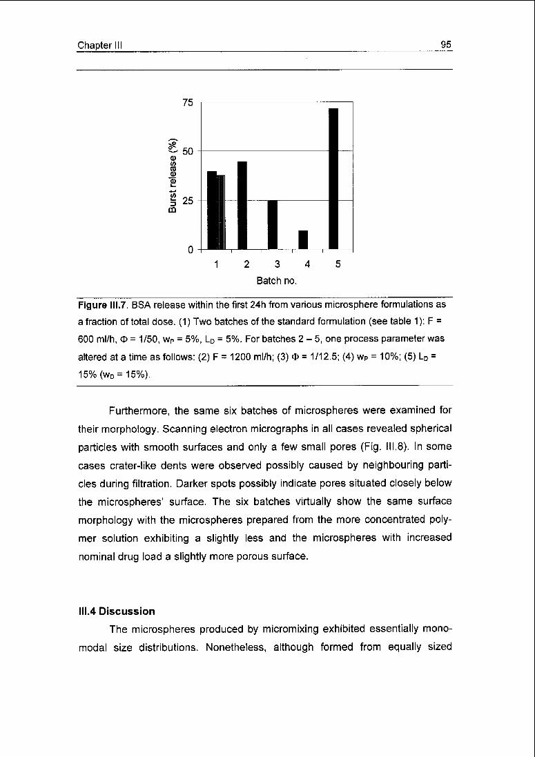
Chapter III 95
12 3 4
Batch no.
Figure III.7. BSA release within the first 24h from various microsphere formulations as
a fraction of total dose. (1) Two batches of the standard formulation (see table 1): F =
600 ml/h, O = 1/50, Wp = 5%, LD = 5%. For batches 2-5, one process parameter was
altered at a time as follows: (2) F = 1200 ml/h; (3) O = 1/12.5; (4) wP = 10%; (5) LD =
15%(wD = 15%).
Furthermore, the same six batches of microspheres were examined for
their morphology. Scanning electron micrographs in all cases revealed spherical
particles with smooth surfaces and only a few small pores (Fig. III.8). In some
cases crater-like dents were observed possibly caused by neighbouring parti¬
cles during filtration. Darker spots possibly indicate pores situated closely below
the microspheres' surface. The six batches virtually show the same surface
morphology with the microspheres prepared from the more concentrated poly¬
mer solution exhibiting a slightly less and the microspheres with increased
nominal drug load a slightly more porous surface.
III.4 Discussion
The microspheres produced by micromixing exhibited essentially mono-
modal size distributions. Nonetheless, although formed from equally sized
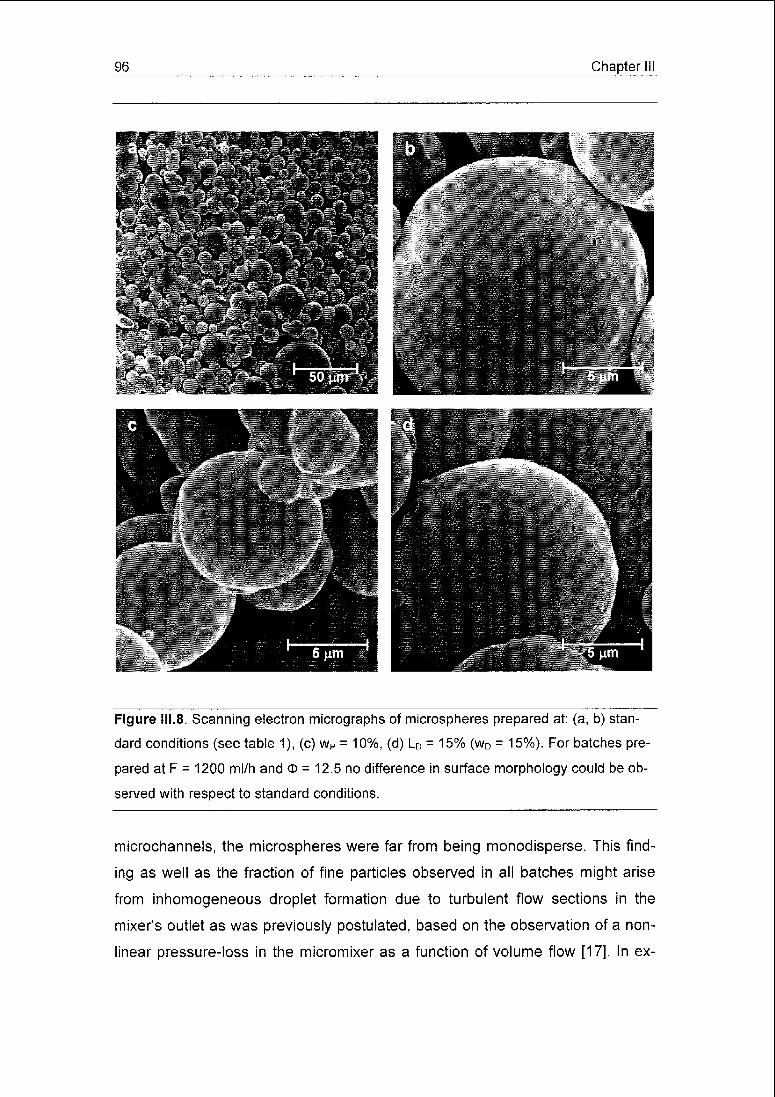
96 Chapter III
Figure III.8. Scanning electron micrographs of microspheres prepared at: (a, b) stan¬
dard conditions (see table 1), (c) wP = 10%, (d) LD = 15% (wD = 15%). For batches pre¬
pared at F = 1200 ml/h and o = 12.5 no difference in surface morphology could be ob¬
served with respect to standard conditions.
microchannels, the microspheres were far from being monodisperse. This find¬
ing as well as the fraction of fine particles observed in all batches might arise
from inhomogeneous droplet formation due to turbulent flow sections in the
mixer's outlet as was previously postulated, based on the observation of a non¬
linear pressure-loss in the micromixer as a function of volume flow [17]. In ex-

Chapter III 97
periments, the authors examined whether the fine particles resulted from frag¬
mentation of nascent microspheres upon entering the collection bath. However,
no evidence for such fragmentation was found.
The size of microdroplets produced by the micromixer basically depends
on three parameters [15], i.e. (i) width of the microchannels, (ii) absolute flow
rates of the fluids to be mixed and (iii) their flow rate ratio. By transition from the
channel array to the outlet slit alternating lamellae of the two fluids are being
formed, which exhibit periodical flow velocity gradients due to a parabolic veloc¬
ity profile in the microchannels (Fig. III.2 d). These gradients cause the lamellae
configuration to become unstable so that the lamellae of the one fluid transform
into droplets, whereas those of the other fluid coalesce to form a continuous
phase. The smaller the width of the microchannels, the smaller the lamellae
and, thus, the theoretical droplet size. Furthermore, an increase in the flow rates
while maintaining the flow rate ratio O augments the velocity gradients and fur¬
ther destabilises the lamellae, thereby yielding smaller droplets. Finally, if the
flow rate ratio is less than unity, i.e. one fluid is fed at lower flow rate than the
other and, thus, enters the outlet slit at a lower velocity, hydrodynamic focussing
occurs: Due to frictional forces, the fluid fed at the lower rate is accelerated re¬
sulting in a thinning of its lamellae and, consequently, in a reduction of particle
size.
Contrary to findings on the dispersion of immiscible fluids [15], it was
found that for the microsphere production the microchannel width did not signifi¬
cantly affect particle size. Of the four microsphere batches produced using the
25 urn tool, two exhibited similar and two only slightly smaller particle sizes than
those obtained with the 40 urn tool. A possible explanation could be the low flow
rate ratio O of 1/50 chosen for these experiments, which may dominate the flow
regime at the mixer's outlet slit and renders the impact of the channel width
secondary. However, in agreement with the above-mentioned dispersions of
immiscible fluids [15], particle sizes deceased markedly with increasing extrac¬
tion fluid flow rate F, which may be used to control effectively the size distribu¬
tion of the microspheres. Additionally, a slight but still significant increase in par¬
ticle size was observed at an increased flow rate ratio O. However, this effect of
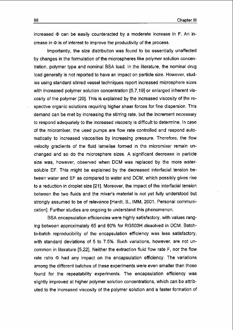
98 Chapter III
increased O can be easily counteracted by a moderate increase in F. An in¬
crease in O is of interest to improve the productivity of the process.
Importantly, the size distribution was found to be essentially unaffected
by changes in the formulation of the microspheres like polymer solution concen¬
tration, polymer type and nominal BSA load. In the literature, the nominal drug
load generally is not reported to have an impact on particle size. However, stud¬
ies using standard stirred vessel techniques report increased microsphere sizes
with increased polymer solution concentration [5,7,19] or enlarged inherent vis¬
cosity of the polymer [20], This is explained by the increased viscosity of the re¬
spective organic solutions requiring higher shear forces for fine dispersion. This
demand can be met by increasing the stirring rate, but the increment necessary
to respond adequately to the increased viscosity is difficult to determine. In case
of the micromixer, the used pumps are flow rate controlled and respond auto¬
matically to increased viscosities by increasing pressure. Therefore, the flow
velocity gradients of the fluid lamellae formed in the micromixer remain un¬
changed and so do the microsphere sizes. A significant decrease in particle
size was, however, observed when DCM was replaced by the more water-
soluble EF. This might be explained by the decreased interfacial tension be¬
tween water and EF as compared to water and DCM, which possibly gives rise
to a reduction in droplet size [21]. Moreover, the impact of the interfacial tension
between the two fluids and the mixer's material is not yet fully understood but
strongly assumed to be of relevance [Hardt, S., IMM, 2001, Personal communi¬
cation]. Further studies are ongoing to understand this phenomenon.
BSA encapsulation efficiencies were highly satisfactory, with values rang¬
ing between approximately 65 and 80% for RG503H dissolved in DCM. Batch-
to-batch reproducibility of the encapsulation efficiency was less satisfactory,
with standard deviations of 5 to 7.5%. Such variations, however, are not un¬
common in literature [5,22]. Neither the extraction fluid flow rate F, nor the flow
rate ratio <I> had any impact on the encapsulation efficiency. The variations
among the different batches of these experiments were even smaller than those
found for the repeatability experiments. The encapsulation efficiency was
slightly improved at higher polymer solution concentrations, which can be attrib¬
uted to the increased viscosity of the polymer solution and a faster formation of
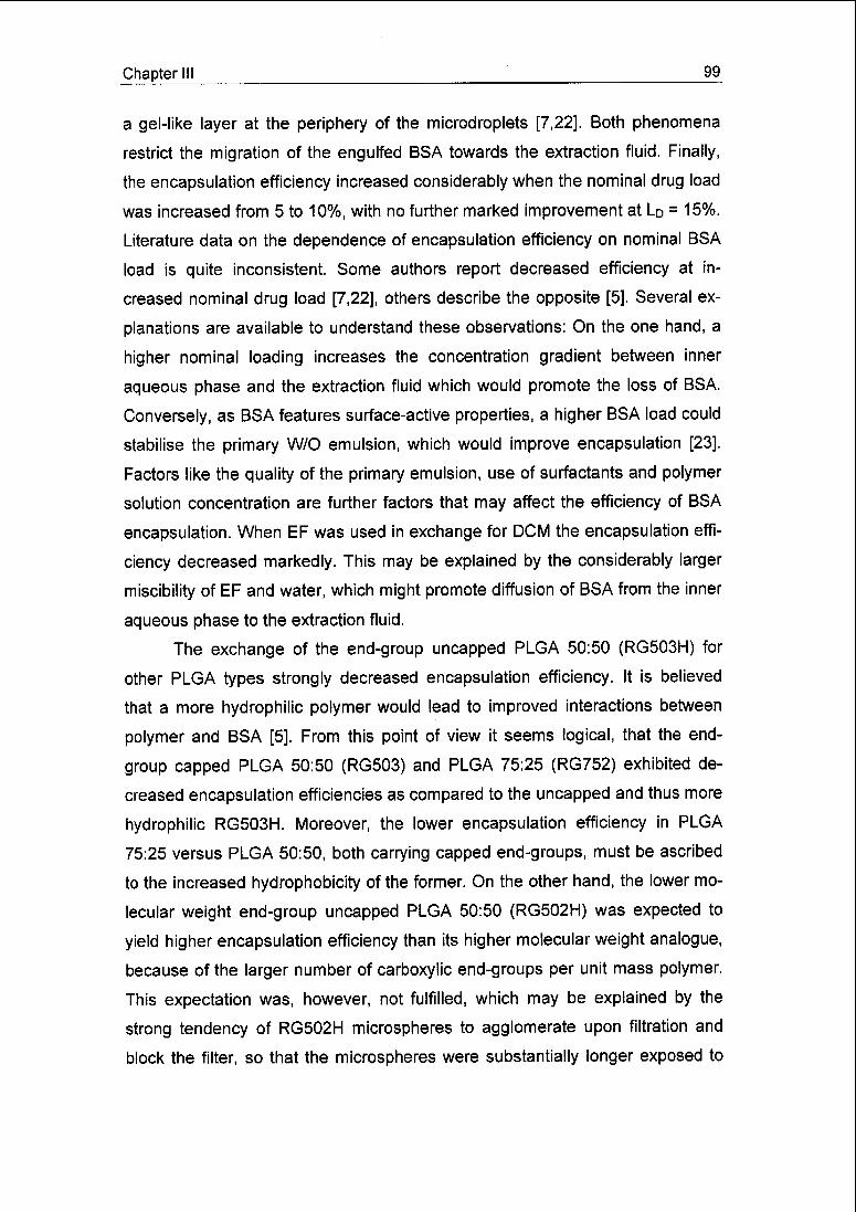
Chapter III 99
a gel-like layer at the periphery of the microdroplets [7,22]. Both phenomena
restrict the migration of the engulfed BSA towards the extraction fluid. Finally,
the encapsulation efficiency increased considerably when the nominal drug load
was increased from 5 to 10%, with no further marked improvement at LD = 15%.
Literature data on the dependence of encapsulation efficiency on nominal BSA
load is quite inconsistent. Some authors report decreased efficiency at in¬
creased nominal drug load [7,22], others describe the opposite [5]. Several ex¬
planations are available to understand these observations: On the one hand, a
higher nominal loading increases the concentration gradient between inner
aqueous phase and the extraction fluid which would promote the loss of BSA.
Conversely, as BSA features surface-active properties, a higher BSA load could
stabilise the primary W/O emulsion, which would improve encapsulation [23].
Factors like the quality of the primary emulsion, use of surfactants and polymer
solution concentration are further factors that may affect the efficiency of BSA
encapsulation. When EF was used in exchange for DCM the encapsulation effi¬
ciency decreased markedly. This may be explained by the considerably larger
miscibility of EF and water, which might promote diffusion of BSA from the inner
aqueous phase to the extraction fluid.
The exchange of the end-group uncapped PLGA 50:50 (RG503H) for
other PLGA types strongly decreased encapsulation efficiency. It is believed
that a more hydrophilic polymer would lead to improved interactions between
polymer and BSA [5]. From this point of view it seems logical, that the end-
group capped PLGA 50:50 (RG503) and PLGA 75:25 (RG752) exhibited de¬
creased encapsulation efficiencies as compared to the uncapped and thus more
hydrophilic RG503H. Moreover, the lower encapsulation efficiency in PLGA
75:25 versus PLGA 50:50, both carrying capped end-groups, must be ascribed
to the increased hydrophobicity of the former. On the other hand, the lower mo¬
lecular weight end-group uncapped PLGA 50:50 (RG502H) was expected to
yield higher encapsulation efficiency than its higher molecular weight analogue,
because of the larger number of carboxylic end-groups per unit mass polymer.
This expectation was, however, not fulfilled, which may be explained by the
strong tendency of RG502H microspheres to agglomerate upon filtration and
block the filter, so that the microspheres were substantially longer exposed to

100 Chapter III
the washing water. Under such conditions, a larger part of the BSA embedded
just close to the surface of the microspheres may have been released into the
washing water.
Finally, microsphere yield was basically unaffected by any variation in
formulation or process parameters and constantly numbered approximately
90-100%.
The release profiles featuring a burst release within the first 24 h without
subsequent release during the following 20 days were unsatisfactory. However,
such profiles are not uncommon in literature [24,25] and attributed to non-
covalent protein aggregation and protein adsorption on the polymer backbone.
It was found that exposure of a protein to an air/liquid interface combined with
high shear forces led to protein aggregation [26]. The dispersion of the aqueous
BSA solution in the organic polymer solution by ultrasonication could have led
to such aggregation due to the presence of high shear forces in addition to an
oil/water interface.
The burst release of 39% of total dose found for the microspheres pre¬
pared under "standard" conditions is rather large. This might be attributed to
pores possibly present closely under the smooth surface. These pores might be
rapidly accessible to the release medium through degradation and mechanical
disruption of the polymer cover. Thus a large surface area would be in contact
with the release medium, giving rise to fast dissolution of BSA. The increase of
the burst release to 45% for the smaller particles prepared at an extraction fluid
flow of 1200 ml/h has to be attributed to the larger specific surface of the
smaller particles. The reduction of the burst release to 25% upon increase of
the flow rate ratio to 1/12.5 might be caused by the reduced concentration gra¬
dient between inner aqueous phase and extraction fluid during preparation of
the particles as the protein/polymer dispersion per unit mass is in contact with
less extraction fluid. A reduced gradient would retard the diffusion of BSA from
the centre to the periphery of the solidifying microsphere where later on it would
be easier accessible to the release medium. The markedly reduced burst re¬
lease found for the 10% polymer solution is probably caused by its larger vis¬
cosity inhibiting the coalescence of the dispersed BSA solution droplets. Thus,
BSA is more finely dispersed in the polymer matrix and less prone to dissolution

Chapter III 101
by the release medium. Moreover, the increased viscosity generally restricts the
diffusion of BSA from the centre to the periphery of the solidifying microsphere.
Finally, a strongly increased burst release was found for a nominal drug load of
15%. As much more BSA is present in the polymer matrix it is more likely that
the BSA inclusions closely neighbour each other. Upon dissolution of the BSA
close to the microspheres' surface further BSA situated deeper in the micro¬
spheres would be rapidly accessible to the release medium.
Among the various approaches to improve the control of microsphere
size distribution in solvent extraction, extrusion through a glass membrane [13]
and the vibrating nozzle technique [14] seem to be the most promising ones.
However, the use of glass membranes [13] for the emulsification of pro¬
tein/polymer dispersions into extraction fluid imposes some drawbacks. For in¬
stance, the size of the microspheres can only be controlled by the pore size of
the membrane. The preparation of very fine particles necessitates glass mem¬
branes with equally small-sized pores, being highly susceptible to clogging upon
contact with polymeric W/O-dispersions. Nevertheless, a clear advantage of the
membrane extrusion technique lies in the very narrow size distributions that can
be obtained.
The vibrating nozzle technique [14] offers a number of powerful features:
Production of monodispersed microspheres, easily adjustable particle size, and
feasibility within a wide range of materials and concentrations. It is believed that
the static micromixer is a powerful alternative when monodispersity is not
needed. The micromixer-based procedure is simple, cheap and space-saving.
Moreover, as the fluids to be mixed can be perfectly contained within a closed
installation, micromixing is ideally suited for the aseptic processing of particulate
polymeric therapeutics embedding difficult to sterilise peptides, proteins, anti¬
gens or oligo- and polynucleotides. Furthermore, lack of moving parts and sim¬
ple set-up simplify disinfection or sterilisation of the micromixer prior to process¬
ing.
Nevertheless, the micromixer offers potential for further improvements.
Re-engineering of the micromixer's outlet section to avoid turbulent flow should
reduce the span of the particle size distribution and prevent the formation of un-
desired fine particles. As particles below 5 urn or even in the sub-micron range

102 Chapter 111
are desirable for a number of applications, re-engineering of the micromixer
should strongly consider this objective. A test reaction performed in the mi¬
cromixer indicated that improved mixing can be achieved by reduction of the
mixer's outlet slit [17]. This measure might reduce the particle size, though
maybe at the risk of higher particle polydispersity. A second measure would be
the reduction of the channel width below 25 urn. However, from the data it is
questionable whether this will have a pronounced effect. Narrower channels
may even render the mixer to become more susceptible to clogging. A further
measure to reduce particle size and, especially, polydispersity might be the re¬
design of the zone of transition from the channel array to the outlet slit, replac¬
ing sharp edges by smoother geometries thus avoiding the creation of turbulent
eddies.
III.5 Conclusions
In this work the potential of a static micromixer consisting of an array of
microchannels was examined with respect to the encapsulation of proteins in
PLGA microspheres by solvent extraction. Being small-sized, of simple set-up,
suitable for continuous production and easy to sterilise, the micromixer seems
to be ideally suited for automated and aseptic production. Scale-up is easily
feasible through the employment of a sufficient number of mixers in parallel.
The mixer proved to produce monomodal particle size distributions with excel¬
lent reproducibility, which were found to be very robust towards changes in the
formulation of the microspheres. Moreover, the particle mean diameter could be
varied in a considerable range by modulating the flow rate of the fluids to be
mixed. High yields and encapsulation efficiencies were obtained which were
unaffected by the modulation of the flow rates. Further research will be directed
towards the production of microspheres in the low micron and sub-micron range
as well as narrower size distributions.

Chapter III 103
Acknowledgements
The authors would like to thank Dr. Ernst Wehrli, Servicelabor für Elek¬
tronenmikroskopie, ETH Zürich, for the preparation of the scanning electron mi¬
crographs.
References
[1] R. Langer, New methods of drug delivery, Science 249 (1990) 1527-
1533.
[2] S. Cohen, T. Yoshioka, M. Lucarelli, L. Hwang, R. Langer, Controlled de¬
livery systems for proteins based on poly(lactic/glycolic acid) micro¬
spheres, Pharm. Res. 8 (1991) 713-720.
[3] G. Kersten, B. Gander, Biodegradable microspheres as vehicles for anti¬
gens, In: Concepts in Vaccine Development, S. Kaufmann (Ed.), Walter
de Gruyter (1996), Berlin.
[4] Y. Ogawa, M. Yamamoto, T. Okada, T. Yashiki, T. Shimamoto, A new
technique to efficiently entrap leuprolide acetate into microcapsules of
polylactic or copoly(lactic/glycolic) acid, Chem. Pharm. Bull. 36 (1988)
1095-1103.
[5] H. Marchais, F. Boury, C. Damgé, J.E. Proust, J.P. Benoit, Formulation
of bovine serum albumin loaded PLGA microspheres. Influence of the
process variables on the loading and in vitro release, STP Pharm. Sei. 6
(1996)417-423.
[6] F. Boury, H. Marchais, J.E. Proust, J.P. Benoit, Bovine serum albumin
release from poly(oc-hydroxy acid) microspheres: Effects of polymer mo¬
lecular weight and surface properties, J. Control. Release 45 (1997) 75-
86.
[7] Y.Y. Yang, T.S. Chung, X.L. Bai, W.K. Chan, Effect of preparation condi¬
tions on morphology and release profiles of biodegradable polymeric mi¬
crospheres containing protein fabricated by double-emulsion method,
Chem. Eng. Sei. 55 (2000) 2223-2236.
[8] Y.F. Maa, C. Hsu, Microencapsulation reactor scale-up by dimensional
analysis, J. Microencapsulation 13 (1996) 53-66.
104 Chapter III
[9] Y.F. Maa, C. Hsu, Liquid-liquid emulsification by static mixers for use in
microencapsulation, J. Microencapsulation 13 (1996) 419-433.
[10] N. Leelarasamee, S.A. Howard, C.J. Malanga, J.K. Ma, A method for the
preparation of polylactic acid microcapsules of controlled particle size
and drug loading, J. Microencapsulation 5 (1988) 147-157.
[11] B. Amsden, The production of uniformly sized polymer microspheres,
Pharm. Res. 16 (1999) 1140-1143.
[12] B.G. Amsden, M.F. Goosen, An examination of factors affecting the size,
distribution and release characteristics of polymer microbeads made us¬
ing electrostatics, J. Control. Release 43 (1997) 183-196.
[13] K. Shiga, N. Muramatsu, T. Kondo, Preparation of poly(D.L-lactide) and
copoly(lactide-glycolide) microspheres of uniform size, J. Pharm. Phar¬
macol. 48 (1996) 891-895.
[14] C. Berkland, K. Kim, D.W. Pack, Fabrication of PLG microspheres with
precisely controlled and monodisperse size distributions, J. Control. Re¬
lease 73 (2001) 59-74.
[15] V. Haverkamp, W. Ehrfeld, K. Gebauer, V. Hessel, H. Löwe, T. Richter,
C. Wille, The potential of micromixers for contacting of disperse liquid
phases, Fresen. J. Anal. Chem. 364 (1999) 617-624.
[16] J. Schiewe, W. Ehrfeld, V. Haverkamp, V. Hessel, H. Löwe, C. Wille, M.
Altvater, R. Rietz, R. Neubert, Micromixer based formation of emulsions
and creams for pharmaceutical applications, Proceed. 4th Int. Conf. on
Microreaction Technol. (2000), Atlanta, USA, 467-477.
[17] W. Ehrfeld, K. Golbig, V. Hessel, H. Löwe, T. Richter, Characterization of
mixing in micromixers by a test reaction: Single mixing units and mixer
arrays, Ind. Eng. Chem. Res. 38 (1999) 1075-1082.
[18] K. Benz, K.P. Jäckel, K.J. Regenauer, J. Schiewe, K. Drese, W. Ehrfeld,
V. Hessel, H. Löwe, Utilization of micromixers for extraction processes,
Chem. Eng. Tech. 24 (2001) 11-17.
[19] P. Sansdrap, A.J. Moës, Influence of manufacturing parameters on the
size characteristics and the release profiles of nifedipine from poly(DL-
lactide-co-glycolide) microspheres, Int. J. Pharm. 98 (1993) 157-164.

Chapter III 105
[20] D. Blanco, M. Alonso, Protein encapsulation and release from
poly(lactide-co-glycolide) microspheres: effect of the protein and polymer
properties and of the co-encapsulation of surfactants, Eur. J. Pharma.
Biopharm. 45 (1998) 285-294.
[21] H. Sah, Microencapsulation techniques using ethyl acetate as a dis¬
persed solvent: effects of its extraction rate on the characteristics of
PLGA microspheres, J. Control. Release 47 (1997) 233-245.
[22] H. Rafati, A.G. Coombes, J. Adler, J. Holland, S.S. Davis, Protein-loaded
poly(DL-lactide-co-glycolide) microparticles for oral administration: formu¬
lation, structural and release characteristics, J. Control. Release 43
(1997)89-102.
[23] Y.F. Maa, C.C. Hsu, Effect of primary emulsions on microsphere size
and protein-loading in the double emulsion process, J. Microencapsula¬
tion 14 (1997) 225-241.
[24] H.K. Kim, T.G. Park, Microencapsulation of human growth hormone
within biodegradable polyester microspheres: protein aggregation stabil¬
ity and incomplete release mechanism, Biotech. Bioeng. 65 (1999) 659-
667.
[25] Y.Y. Yang, H.H. Chia, T.S. Chung, Effect of preparation temperature on
the characteristics and release profiles of PLGA microspheres containing
protein fabricated by double-emulsion solvent extraction/evaporation
method, J. Control. Release 69 (2000) 81-96.
[26] Y.F. Maa, C.C. Hsu, Protein denaturation by combined effect of
shearand air-liquid interface, Biotech. Bioeng. 54 (1997) 503-512.
106 Chapter III
Seite Leer /
Blank leaf

Chapter IV 107
Chapter IV
Flow-through ultrasonic emulsification combined with static micromixing
for aseptic production of microspheres by solvent extraction
Sergio Freitas, Beat Rudolf, Hans P. Merkle, and Bruno Gander
Department of Chemistry and Applied Biosciences, Institute of Pharmaceutical Sci¬
ences, Swiss Federal Institute of Technology Zürich, ETH Hönggerberg HCl,
8093 Zürich, Switzerland
European Journal of Pharmaceutics and Biopharmaceutics, 61 (2005) 181-187

108 Chapter IV
IV.1 Introduction
Administration of biodegradable microspheres for drug and antigen deliv¬
ery is primarily via the parenteral route. Thus, product sterility has to be as¬
sured. Standard laboratory procedures yield microbiologically contaminated par¬
ticles [1,2]. Microbial contamination mostly originates from human cutaneous
flora and non-sterilised equipment. To yield a sterile product, two approaches
may be followed: (i) terminal sterilisation of the product or (ii) aseptic manufac¬
turing.
The most common matrix materials used to formulate biodegradable mi¬
crospheres for parenteral drug delivery are poly(lactic acid), PLA, and
poly(lactic-co-glycolic acid), PLGA. PLA and PLGA microspheres cannot be
sterilised by heat or steam, because of the low glass transition temperature of
these polymers, while the use of ethylene oxide may result in toxic residues.
Therefore, y-irradiation remains the only acceptable sterilisation method. How¬
ever, it has been shown that y-irradiation causes radiolytic chain scission result¬
ing in polymer molecular weight reduction, and thus alters drug release [1,2,3].
Moreover, damage to the active principle may occur [2]. As a result, aseptic mi¬
crosphere manufacturing should be favoured over terminal sterilisation of PLA
and PLGA microspheres.
Very commonly, microencapsulation is based on the so-called solvent
extraction method. Lab-scale experiments are frequently performed in a simple
beaker/stirrer set-up, which is not well suitable for aseptic manufacturing as it
involves a series of manual operations and is entirely unsuitable for scaling-up
[4,5], Although a vast number of modified processes have been developed [6],
only very few of them have been specifically designed for aseptic microsphere
preparation, requiring specialised, cost-intensive equipment [7].
In this study, BSA-loaded PLGA microspheres were prepared by means
of a W1/0/W2-double emulsion solvent extraction method [4]. A flow-through ul¬
trasonic cell for the preparation of the primary W1/O emulsion was combined
with a static micromixer for the preparation of the Wi/OAA/2-double emulsion.
This equipment offers a number of advantages with respect to aseptic micro¬
sphere preparation, e.g., small scale, low complexity, moderate cost equipment
and easy handling, cleaning and assembling. Therefore, the proposed technol-

Chapter IV 109
ogy appears suitable for cost-efficient aseptic production of drug-loaded micro¬
spheres in amounts suitable, e.g., for use in clinical studies. The prepared mi¬
crospheres were characterised with respect to particle size, drug loading and,
for those prepared under aseptic conditions, for absence of microbial contami¬
nation.
IV.2 Materials and methods
IV.2.1 Materials
Uncapped, 35 kDa poly(lactic-co-glycolic acid), PLGA (Resomer®
RG503H) was purchased from Boehringer-lngelheim (Ingelheim, Germany).
Bovine serum albumin (BSA, fraction V) was from Fluka (Buchs, Switzerland).
Polyvinyl alcohol) (PVA, Mowiol® 4-88) and polysorbate 20, used as dispersion
stabilisers, were obtained from Kuraray Specialities (Frankfurt/M., Germany)
and Hänseier (Herisau, Switzerland), respectively.
IV.2.2 Experimental set-up
BSA-loaded PLGA microspheres were prepared using a recently devel¬
oped micromixer-based double-emulsion solvent extraction method [8]. The ex¬
perimental set-up consisted of three serially connected subunits (Fig. IV. 1).
First, an aqueous BSA solution (W-i) and a solution of PLGA in an organic sol¬
vent (O), both fed by syringe pumps, were pre-mixed in a 1 ml rubber-sealed
glass cell by means of a magnetic stirrer. Second, the resulting coarse W1/O-
emulsion was transported into a flow-through ultrasonic cell (Dmini250,
Dr. Hielscher, Teltow, Germany; Fig. IV.2) for homogenisation. The homoge¬
nised emulsion was further transported to a 3 ml rubber-sealed glass receptacle
used as expansion vessel to decouple the Wi/O-emulsification from the follow¬
ing process step. Third, the Wi/O-emulsion was further emulsified in an aque¬
ous extraction fluid (W2) using a static micromixer (SSIMMAg40T35, Institut für
Mikrotechnik Mainz (IMM), Mainz, Germany; Fig. IV.3 a). The resulting Wi/OA/V2
double emulsion was collected in a glass vessel and stirred gently. Upon extrac¬
tion of the polymer solvent into the extraction fluid W2, solid microspheres with
encapsulated protein were formed.

110 Chapter IV
ä £No <_. 5H^ i?
cS S
+•»»+ flj
_2
3 (y)
static micromixer©@> |
• «1
18 >
V !here ionCL *->
rosU 0
c L 'Ê u
° — I
ro s Hi©x L
.y**
i
T3 **» 1
C H^gga 11« iy^ i
* 3 -** 1
tras< ce ri ress ater—
pi CL g"*^Hi ^
-"
i
0re- xer
u
E m
nagneti tïî
fc) 0
en
pumpsWl
g
o
iï
i
XI +3
O £
o
? o
O ja
M
o
y
<u
O
,g
E
S!a.
Q
Figure IV.1. Schematic overview of the microsphere preparation process, consisting of
three main steps: (i) Wi/O pre-emulsification, (ii) W^O emulsion homogenisation, and
(iii) \NJOr\N2 double emulsion formation. The numbers © to © indicate the sampling
points for sterility testing (see text for details).
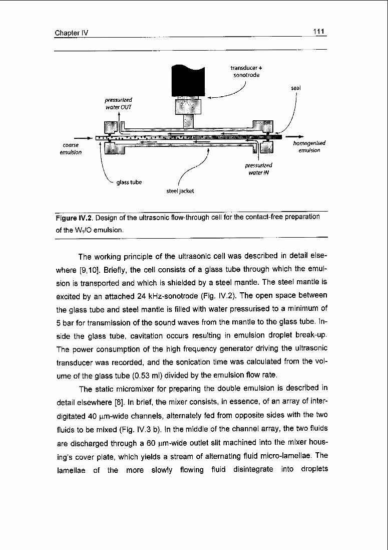
Chapter IV 111
^^ pressurized
f water IN
glass tube (steel jacket
Figure IV.2. Design of the ultrasonic flow-through cell for the contact-free preparation
of the Wi/0 emulsion.
The working principle of the ultrasonic cell was described in detail else¬
where [9,10]. Briefly, the cell consists of a glass tube through which the emul¬
sion is transported and which is shielded by a steel mantle. The steel mantle is
excited by an attached 24 kHz-sonotrode (Fig. IV.2). The open space between
the glass tube and steel mantle is filled with water pressurised to a minimum of
5 bar for transmission of the sound waves from the mantle to the glass tube. In¬
side the glass tube, cavitation occurs resulting in emulsion droplet break-up.
The power consumption of the high frequency generator driving the ultrasonic
transducer was recorded, and the sonication time was calculated from the vol¬
ume of the glass tube (0.53 ml) divided by the emulsion flow rate.
The static micromixer for preparing the double emulsion is described in
detail elsewhere [8]. In brief, the mixer consists, in essence, of an array of inter-
digitated 40 [tm-wide channels, alternately fed from opposite sides with the two
fluids to be mixed (Fig. IV.3 b). In the middle of the channel array, the two fluids
are discharged through a 60 urn-wide outlet slit machined into the mixer hous¬
ing's cover plate, which yields a stream of alternating fluid micro-lamellae. The
lamellae of the more slowly flowing fluid disintegrate into droplets
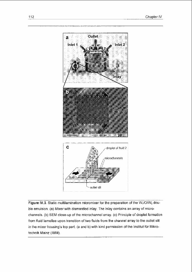
112 Chapter IV
Figure IV.3. Static multilamination micromixer for the preparation of the Wi/0/W2 dou¬
ble emulsion, (a) Mixer with dismantled inlay. The inlay contains an array of micro-
channels, (b) SEM close-up of the microchannel array, (c) Principle of droplet formation
from fluid lamellae upon transition of two fluids from the channel array to the outlet slit
in the mixer housing's top part, (a and b) with kind permission of the Institut für Mikro-
technik Mainz (IMM).
Chapter IV 113
(Fig. IV.3 c) [8,12]. The size of the droplets can be readily controlled by varying
the flow velocities of the two fluids [8].
IV.2.3 Microsphere preparation
PLGA was dissolved in dichloromethane (DCM) or ethyl formate (EF) at
6% (w/w) (O) and BSA in PBS at 5% (w/w) (Wi). The two solutions were proc¬
essed by the ultrasonic cell as described above. The portion of Wi/0 emulsion
discharged from the ultrasonic cell during the first 5 min of processing was dis¬
carded to let the process equilibrate. Aqueous 0.5% (w/w) solutions of PVA or
polysorbate 20 were used as extraction fluids (W2) for DCM and EF, respec¬
tively. Flow rates were set at 4, 45 and 360 ml/h for the Wr, O- and W2-phases,
respectively. The dispersion of nascent microspheres discharged from the mi¬
cromixer was collected in a glass vessel pre-filled with 500 ml of extraction fluid
and stirred gently for 30 (EF) or 120 min (DCM) for further hardening. The mi¬
crospheres were collected over a 0.2 urn pore-size filter, washed with 50 ml of
de-ionised water and dried at 20 mbar and room temperature for 24 h. For each
set of preparation parameters, three microsphere batches (400-500 mg/batch)
were prepared and analysed.
IV.2.4 Droplet size distribution of the Wi/0 emulsion
Samples of the W-i/O emulsions were taken from the expansion vessel
placed between ultrasonic cell and micromixer, diluted 250-fold with DCM satu¬
rated with water, and analysed by laser light scattering (Mastersizer X, Malvern,
Worcestershire, UK) using the Mie diffraction model. The refractive indices of
the BSA solution and diluted polymer solution were approximated by those of
water and DCM. The emulsion droplet size distributions are presented in the
volume-weighted mode and characterised by the mean diameter calculated
from the volume-moment average of the size distribution, D[4,3].
IV.2.5 Microsphere size distribution
Dispersions of the microspheres in the extraction fluid were analysed by
laser light scattering (see above). Here, the Fraunhofer model was chosen for
raw data analysis.

114 Chapter IV
IV.2.6 Protein content in the microspheres
The BSA content in the microspheres was quantified as described else¬
where [8]. Briefly, samples of 40 mg of dried microspheres were dissolved in
DCM. BSA was separated from the dissolved polymer by filtration over a 0.2 urn
pore-size regenerated cellulose filter. After elution of the protein from the filter
into PBS, the resulting solution was analysed fluorimetrically. The encapsulation
efficiency was expressed as the ratio of the amount of BSA extracted from the
microspheres to the amount of BSA employed for their preparation. Each mi¬
crosphere batch was assayed in duplicate.
IV.2.7 Aseptic microsphere production and sterility testing
To evaluate the feasibility of the described technology for aseptic manu¬
facturing, a number of microsphere batches were prepared under aseptic condi¬
tions and tested for sterility.
Syringes, pre-mixing cell, expansion vessel, glassware, tubing, as well as
the dismantled micromixer and the glass tube of the ultrasonic cell (Fig. IV.2)
were steam-sterilized, while the remaining parts of the equipment were surface-
disinfected with 70% ethanol. The experimental set-up was set together in a
laminar air-flow cabinet and finally purged with 70% ethanol.
The BSA and PLGA solutions were subject to sterile filtration over 0.2 (am
cellulose acetate and PTFE filters, respectively, while the PVA and polysorbate
solutions (extraction fluids) were steam-sterilised at 121°C and 2 bar for 15 min.
For validation of the sterilisation methods, all solutions involved in the process
were loaded with a defined bioburden of 1:1-mixtures of Bacillus subtilis and
Candida albicans. Volumes of 10 ml of both BSA and PLGA solutions were
separately loaded with 7 x 10⁶ CFU/ml of the microbial mixture to achieve a
bioburden of 107 CFU/cmz for sterile filtration on 7 cm2 cross-section membrane
filters. Typically, 10 ml of PLGA solution was used to produce one microsphere
batch. The extraction fluid was loaded with 106 CFU per 100 ml of the microbial
mixture. All contaminated solutions were found to be sterile after sterile filtration
or steam sterilisation (for sterility testing method see below).
During microsphere production, sterility tests were performed with the
BSA and PLGA solutions, the extraction fluid (Fig. IV.1, sampling points

Chapter IV 115
® to <3>), the W^O emulsion (©), the hardened microspheres (©) and the ex¬
traction fluid waste (©). Aliquots of the BSA solution (5 ml), the extraction fluid
and extraction fluid waste (25 ml each) were mixed with casein-peptone-
soypeptone (CASO) broth, incubated for 24 h at ambient conditions, filtered us¬
ing a Milliflex 100 system (Millipore, Massachusetts, USA), and the filters incu¬
bated with tryptic soy broth (TSB). Incubation conditions were 30-35 °C,
14 days for bacterial growth, and 20-25 °C, 14 days for growth of yeast and
moulds. The filters were checked daily for colony growth. The PLGA solution
was tested by filtering first over a sterile 0.2 urn regenerated cellulose filter, then
re-hydrating the filter [13], and incubating it in CASO broth for 24 h. Then the
broth was further processed as described above. Samples of the W1/O-
emulsion were diluted (1:6, v/v) in sterile ethyl formate and processed in anal¬
ogy to the PLGA solution. The microspheres dispersed in the extraction fluid
were collected on a sterile 0.2 ^m cellulose acetate filter. One portion of the col¬
lected particles was mixed with CASO broth, incubated for 24 h, and the
broth/particle-mixture was further processed using the Millipore system as de¬
scribed above. Another portion was dissolved in 5 ml of sterile EF and proc¬
essed further as described for the PLGA solution.
Positive controls were performed by direct incubation of the test bacteria
and yeast (88 CFU of each) in TSB. The controls showed colony growth after
three days of incubation. Sterility and control tests were carried out in triplicate.
IV.3 Results and discussion
IV.3.1 Process and microsphere characteristics
Pre-mixing of the BSA solution in the PLGA-solution produced aqueous
droplets of a size of typically < 200 fim [9]. Pre-mixing was necessary to ensure
that the composition of the W-i/O-feed entering the ultrasonic flow-through cell
remained constant. Processing of the coarse pre-emulsion by the ultrasonic cell
reduced the mean droplet size of the W-i/O-emulsion to 620 - 670 nm
(Tab. IV.1). The droplet size distributions were monomodal and relatively nar¬
row with negligible batch-to-batch variations (Fig. IV.4). The mean droplet size
of the W-i/O-emulsion was 620 nm when the maximum sonication power of
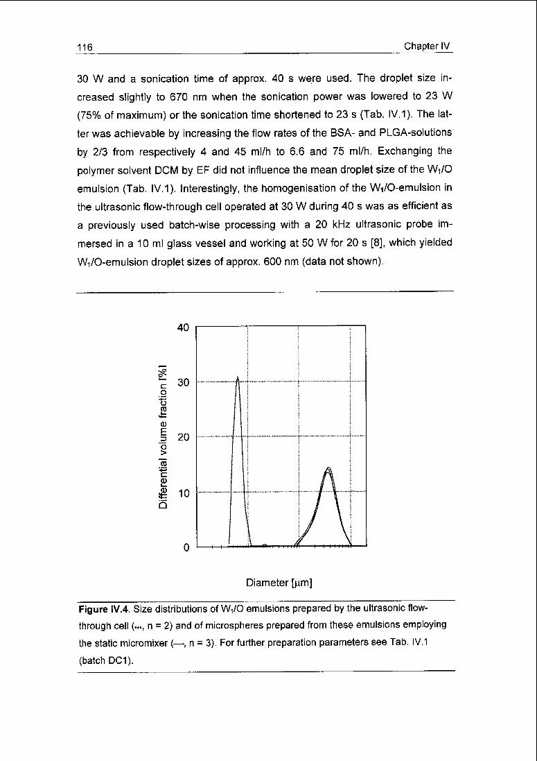
116 Chapter IV
30 W and a sonication time of approx. 40 s were used. The droplet size in¬
creased slightly to 670 nm when the sonication power was lowered to 23 W
(75% of maximum) or the sonication time shortened to 23 s (Tab. IV.1). The lat¬
ter was achievable by increasing the flow rates of the BSA- and PLGA-solutions
by 2/3 from respectively 4 and 45 ml/h to 6.6 and 75 ml/h. Exchanging the
polymer solvent DCM by EF did not influence the mean droplet size of the Wi/0
emulsion (Tab. IV.1). Interestingly, the homogenisation of the Wi/O-emulsion in
the ultrasonic flow-through cell operated at 30 W during 40 s was as efficient as
a previously used batch-wise processing with a 20 kHz ultrasonic probe im¬
mersed in a 10 ml glass vessel and working at 50 W for 20 s [8], which yielded
Wi/O-emulsion droplet sizes of approx. 600 nm (data not shown)
40
g
&
E_3O>
Ǥb
30
20
10
Diameter [urn]
Figure IV.4. Size distributions of Wi/0 emulsions prepared by the ultrasonic flow-
through cell («., n = 2) and of microspheres prepared from these emulsions employing
the static micromixer (—, n = 3) For further preparation parameters see Tab. IV.1
(batch DC1).

Chapter IV 117
Table IV.1. Characteristics of BSA-loaded microspheres prepared under different con¬
ditions of primary emulsion (W^O) and double emulsion (VvyOAAk) formation. Data are
given as mean of three microsphere batches ± S.D.
Batch Sonica- Sonica- Polymer Mean W^O Mean Theoret. EncapsulationID tion tion solvent droplet microsphere drug efficiency
power time diameter diameter loading
D[4,3] D[4,3]
[Gm] [Dm] [%] [%]
[W] [s]
DC1 30 39 DCM 0.62 ±0.05 36.4 ±0.8 5.6 73.0 ±3.6
DC2 23 39 DCM 0.67 ±0.03 38.9 + 1.7 5.6 72.5 ±1.2
DC3 30 23 DCM 0.67 ±0.05 30.9 ±0.3 5.6 67.1 ±2.5
EF1 30 40 EF 0.63 ± 0.03 14.8 ±0.2 6.0 70.2 ±3.7
Between the ultrasonic cell and the micromixer, an expansion vessel had
to be installed to decouple the fluid processing in the ultrasonic cell, which oc¬
curred at ambient pressure, from the fluid processing in the micromixer, occur¬
ring at a slightly higher pressure due to the pressure drop in the mixer. An in¬
creased pressure during the ultrasonication of the Wi/O-emulsion reduced the
homogeneity of the emulsion, because of less efficient cavitation. Enhanced
pressure increases the threshold for the onset of cavitation, resulting in a de¬
creased number of cavitation events per unit volume of emulsion [14].
Microsphere formation in the micromixer occurred through extruding the
Wi/O-emulsion through an array of interdigitated microchannels that were fed
from the opposite side by the extraction fluid, W2, and further through a fine gap
(the micromixer's outlet slit). Specifically, W^O-droplets in the W2-phase formed
by friction forces exerted on the slowly flowing Wi/O-lamellae by the nine-fold
faster flowing W2-lamellae. This W-i/O-droplet formation was accompanied by
simultaneous solvent extraction giving birth to microspheres of relatively broad
size distribution (Fig. IV.4), as previously found in earlier experiments with this
type of mixer [8], Batch-to-batch reproducibility was highly satisfactory. Micro¬
sphere sizes were not affected by the slight changes of the W-i/O-emulsion

118 Chapter IV
droplet size upon reduction of the sonication power (Tab. IV.1). The reduction of
the sonication time by increasing the flow rates of the Wi- and O-solutions, in
turn, necessitated to increase the flow-rate of the extraction fluid, W2, from 360
to 420 ml/h in order to maintain stable emulsification in the static micromixer,
resulting in a decrease of the microsphere mean size from 36 jam to 31 urn. Mi¬
crosphere sizes were reduced substantially, i.e., from above 36 to 15 urn when
DCM was exchanged for EF. Both observations are in agreement with earlier
experiments using this type of micromixer [8]. An explanation for the decreased
microsphere size with the use of EF may be the lower interfacial tension be¬
tween EF and the aqueous extraction fluid, which may have facilitated droplet
break-up.
The microencapsulation of BSA by this continuous process yielded en¬
capsulation efficiencies (approx. 70%; Tab. IV.1), which were similar to those
obtained previously with the same micromixer in combination with a batch-mode
preparation of the Wi/O-emulsion using a standard ultrasonic probe immersed
in a glass vessel [8]. The encapsulation efficiency was not significantly influ¬
enced by the small differences in the Wi -droplet sizes (620-670 nm) of the pri¬
mary W-i/O-emulsion, nor by the exchange of polymer solvent, although EF
produced much smaller microspheres than DCM. For similar experiments with
EF, in which a standard ultrasonic probe and the micromixer were used, the at¬
tained encapsulation efficiency was only 60% and varied largely between the
batches [8].
IV.3.2 Aseptic production
The combination of ultrasonic flow-through cell and static micromixer of¬
fers specific advantages for aseptic processing of drug-loaded microspheres.
The entire production unit is small and fits readily into a laminar-flow cabinet or
an isolator. The static micromixer consists basically of only three parts, which all
can be heat-sterilised. The glass tube which conducts the Wi/0 emulsion can
be dismantled from the ultrasonic cell and heat-sterilised, as all other tubing as
well. Thanks to the low complexity of the equipment, the few sterilised parts can
be readily assembled in a Class 100 containment. The unit allows for continu¬
ous production requiring minimum manual handling, which is a prerequisite for
Chapter IV 119
cost-efficient aseptic production, and obviates contact between the processed
materials and the environment.
None of the samples taken for sterility testing from the starting materials,
intermediate and final products showed microbial contamination. For sterility
testing of the microspheres, we firstly incubated them directly to check for sur¬
face contamination. The absence of surface contaminations was confirmed by
sterility testing of the extraction fluid waste. Secondly, the microspheres were
dissolved in EF, the obtained solutions sterile filtered, the filters re-hydrated and
incubated to test for microorganisms entrapped in the core. Although the use of
solvents like DCM for microsphere production could have reduced the risk of
core contamination by killing vegetative forms of bacteria, yeasts and moulds,
the more resistent spores could have survived this process [1,13,15].
In conclusion, the primary goal of this work was to obtain first information
on the feasibility of aseptic microsphere preparation combining the flow-through
ultrasonic cell and the multilamination micromixer. We are well aware that the
sterility tests performed are by no means sufficient to validate product sterility
on a GMP-level. Further work will have to include testing for anaerobe microor¬
ganisms. In addition, the method used for testing the sterility of the microsphere
cores needs further validation work with respect to the microbial toxicity of EF,
which was employed for the dissolution of the microspheres.
References
[1] A. Gèze, M. Venier-Julienne, J. Cottin, N. Faisant, J. Benoit, PLGA mi¬
crosphere bioburden evaluation for radiosterilization dose selection, J.
Microencapsulation 18 (2001) 627-636.
[2] D. Mohr, M. Wolff, T. Kissel, Gamma irradiation for terminal sterilization
of 17ß-estradiol loaded poly-(D,L-lactide-co-glycolide) microspheres, J.
Control. Release 61 (1999) 203-217.
[3] A. Hausberger, R. Kenley, P.P. De Luca, Gamma irradiation effects on
molecular weight and in vitro degradation of poly(D,L-lactide-co-
glycolide) microparticles, Pharm. Res. 12 (1995) 851-856.

120 Chapter IV
[4] P. O'Donnell, J. McGinity, Preparation of microspheres by the solvent
evaporation technique, Adv. Drug. Deliv. Rev. 28 (1997) 25-42.
[5] Y. Yang, T. Chung, X. Bai, W. Chan, Effect of preparation conditions on
morphology and release profiles of biodegradable polymeric micro¬
spheres containing protein fabricated by double-emulsion method,
Chem. Eng. Sei. 55 (2000) 2223-2236.
[6] S. Freitas, H.P. Merkle, B. Gander, Microencapsulation by solvent ex¬
traction/evaporation: reviewing the state of the art of microsphere prepa¬
ration process technology, J. Control. Release, in press.
[7] M. Tracy, Development and scale-up of a microsphere protein delivery
system, Biotechnol. Prog. 14 (1998) 108-115.
[8] S. Freitas, A. Walz, H.P. Merkle, B. Gander, Solvent extraction employ¬
ing a static micromixer: a simple, robust and versatile technology for the
microencapsulation of proteins, J. Microencapsulation 20 (2003) 67-85.
[9] S. Freitas, G. Hielscher, H.P. Merkle, B. Gander, Continuous contact-
and contamination-free ultrasonic emulsification - a useful tool for phar¬
maceutical development and production, Ultrasonics Sonochem., ac¬
cepted.
[10] S. Freitas, B. Gander, N. Lehmann, Verfahren und Durchflusszelle zur
kontinuierlichen Bearbeitung von fliessfähigen Zusammensetzungen mit¬
tels Ultraschall, German Patent Application 102 43 837, 2002.
[12] V. Haverkamp, W. Ehrfeld, K. Gebauer, V. Hessel, H. Löwe, T. Richter,
C. Wille, The potential of micromixers for contacting of disperse liquid
phases, Fresen. J. Anal. Chem. 364 (1999) 617-624.
[13] F. Furkert, A validated test for sterility of microparticles made of
poly(lactide-co-glycolide), Pharm. Ind. 60 (1998) 905-907.
[14] O. Behrend, H. Schubert, Influence of hydrostatic pressure and gas con¬
tent on continuous ultrasound emulsification, Ultrasonics Sonochem. 8
(2001)271-276.
[15] H. Toguchi, Sterility assurance of microspheres, J. Control. Release
(1999)51-55.
Chapter V 121
Chapter V
Ultrasonic atomisation into reduced pressure atmosphere - envisaging
aseptic spray-drying for microencapsulation
Sergio Freitas, Hans P. Merkle, and Bruno Gander
Department of Chemistry and Applied Biosciences, Institute of Pharmaceutical Sci¬
ences, Swiss Federal Institute of Technology Zürich, ETH Hönggerberg HCl,
8093 Zürich, Switzerland
Journal of Controlled Release, 95 (2004) 185-195

122 Chapter V
V.1 Introduction
The embedding of pharmaceutical compounds into bioerodible micro¬
spheres has gained considerable interest over the last decade as it opens the
door to a variety of therapeutic applications. Drugs can be released from such
microparticles in a sustained and controlled fashion, while non-released drug is
protected from degradation [1]. Furthermore, microparticles may be surface-
modified for targeting specific tissues or cells [2]. Various materials have been
used for such microspheres, amongst them lipids, proteins and a vast number
of biodegradable polymers. The most frequently used biodegradable polymers
are the polyesters poly(lactic acid), PLA, and poly(lactic-co-glycolic acid),
PLGA, as they are well tolerated and degrade to toxicologically harmless prod¬
ucts.
Besides solvent extraction/evaporation and phase separation (coacerva¬
tion), spray-drying is the method most frequently employed for microsphere
preparation. Standard laboratory spray-dryers consist of a pneumatic spray
nozzle, an aspirator coupled with a heating to provide hot air, a drying chamber,
a system for recovering the dried particles and a system clearing the exhaust
air, e.g., a bag filter. Separation of particles from the heat-providing and trans¬
porting stream of air commonly occurs in a cyclone, although filter systems may
also be used. Both methods of particle separation incorporate specific draw¬
backs. Filtration requires continuous removal of the collected product from the
filter in order to keep the pressure drop constant. A cyclone does not work
equally efficient for different particle sizes and airflows. Especially particles of
less than 5 urn in diameter are inefficiently separated so that a considerable
part of the product may be lost with the exhaust air [3]. Moreover, small parti¬
cles tend to deposit on the cyclone wall, which is typically caused by electro¬
static interaction [4]. Nonetheless, variations in cyclone and receiver design,
improvement in the exhaust air management by using a vacuum filter system
and the use of dual- or anti-static cyclone set-ups may all contribute to reduced
product loss [3]. Generally, product loss becomes less pronounced with larger
batch sizes [5].
Aseptic microencapsulation is increasingly demanded because numer¬
ous biodegradable materials, such as PLA or PLGA, cannot be heat-sterilised
Chapter V 123
and sterilisation by gamma rays may harm the encapsulated drug and degrade
the polymer [6]. However, aseptic preparation of microspheres by conventional
spray-drying is difficult to achieve. The stream of drying air has to be passed
through a sterilisation filter resulting in a considerable pressure drop, which
might negatively affect the dryer's performance in terms of particle separation.
Moreover, particles deposited on the cyclone wall might have to be recovered
by washing [3,4] which is most delicate for aseptic production.
To make aseptic spray-drying more economic and feasible in laboratory
environments, we developed a process consisting of an ultrasonic spray-head
for the disruption of a solution into microdroplets, a vessel kept under reduced
pressure for drying of the microdroplets and a bath of a non- or antisolvent for
collection and if necessary final desolvation of the resulting particles. The veloc¬
ity of the microdroplets ejected from an ultrasonic nozzle is one to two orders of
magnitude smaller than in pressurised nozzles, so that the drying chamber can
be of considerably shorter dimensions. Thus, the apparatus can be readily in¬
stalled in a laminar flow cabinet or isolator. Reduced pressure as the driving
force for the evaporation of the solvent from the microdroplets obviates the
need for large quantities of sterile hot air. A cyclone or filter-system is not
needed as the formed particles settle into the collection fluid, which can be com¬
fortably withdrawn from the apparatus. Additionally, the collection bath can be
used to surface-modify the particles, e.g. by adsorption of a substance dis¬
solved in the bath.
Microsphere production using an ultrasonic spray-head equipped to a
standard laboratory spray-dryer is reported in literature [5]. However, as the dry¬
ing (warm air) and particle collection mechanisms remained unaltered, the sys¬
tem offers little benefit with respect to aseptic preparation. Furthermore, direct
ultrasonic spraying into an antisolvent without previous drying is reported [7,8].
The aim of this study was to evaluate the potential of the novel spray-
drying process for the preparation of protein-loaded PLA and PLGA microparti¬
cles. Bovine serum albumin (BSA) was chosen as model protein and the influ¬
ence of various process and formulation parameters on the characteristics of
the resulting microparticles was studied.

124 Chapter V
V.2 Materials and methods
V.2.1 Materials
End-group uncapped 14.6 kDa PLA (Resomer® R202H; molecular
weights given are weight-averaged according to [9]), end-group uncapped
13.7 kDa and 35 kDa PLGA50:50 (Resomer® RG502H and RG503H) and end-
group capped 41.2 kDa PLGA50:50 (Resomer® RG504) were purchased from
Boehringer-lngelheim (Ingelheim, Germany). Bovine serum albumin (BSA, frac¬
tion V) was from Fluka (Buchs, Switzerland) and polysorbate-20 from Hänseier
(Herisau, Switzerland). Synthesis grade dichloromethane (DCM) and ethyl ace¬
tate (EA) were from EGT Chemie (Scharlau, Switzerland), ethyl formate (EF)
was obtained from Fluka. Purified water was obtained from a NANOpure ul¬
trapure water system (Barnstead, Dubuque, USA).
vacuum
pump
150
150
S©3I
400
magneticstir bar
pre-formedprotein/polymer dispersion
synnge pump
US spray head
removable
cylinders
microspheres dispersedin collection fluid
outlet
200
Figure V.1 a. Sketch of the vacuum spray-dryer.
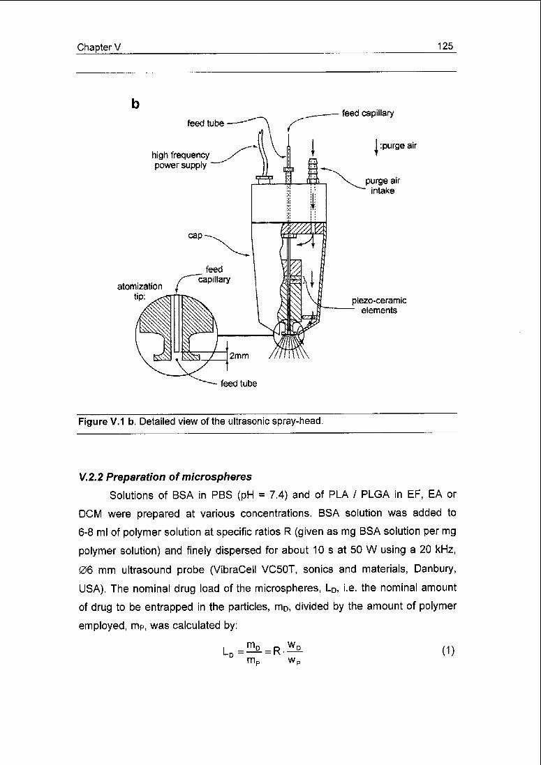
Chapter V 125
feed tube
high frequency
power supply
atomization
tip:ptezo-ceramic
elements
feed tube
Figure V.1 b. Detailed view of the ultrasonic spray-head.
V.2.2 Preparation of microspheres
Solutions of BSA in PBS (pH = 7.4) and of PLA / PLGA in EF, EA or
DCM were prepared at various concentrations. BSA solution was added to
6-8 ml of polymer solution at specific ratios R (given as mg BSA solution per mg
polymer solution) and finely dispersed for about 10 s at 50 W using a 20 kHz,
06 mm ultrasound probe (VibraCell VC50T, sonics and materials, Danbury,
USA). The nominal drug load of the microspheres, LD, i.e. the nominal amount
of drug to be entrapped in the particles, mD, divided by the amount of polymer
employed, mp, was calculated by:
LD=^ = R.^mc wc
(1)

126 Chapter V
where wD and wP denote the weight fraction of the drug and the polymer in their
respective solutions.
The protein/polymer dispersion was transferred into a 20 ml single-use
syringe and by means of a syringe pump (syritrol 12, Heinzerling Medizintech¬
nik, Rotenburg a.d. Fulda, Germany) fed to a 100 kHz ultrasonic spray head
(US1, Lechler, Metzingen, Germany) installed in a glass vessel (Fig. V.1). The
vessel was kept under reduced pressure controlled precisely by a vacuum
pump (LVS 610T ecoflex, llmvac, Ilmenau, Germany), to evaporate the solvent
from the fine droplets formed by the ultrasonic head. A throttle valve was in¬
stalled between syringe and spray head to prevent the protein/polymer disper¬
sion from being uncontrollably drawn into the glass vessel. The resulting micro¬
spheres settled into 1.5 I of aqueous polysorbate-20 solution (0.5% w/w) filled
into the bottom of the glass vessel for collection and harvest of the spheres. At
the end of product atomisation, the microspheres were allowed to remain dis¬
persed in the collection fluid for 5 min while the spray head was purged with
pure solvent. The microsphere dispersion was then drained from the glass ves¬
sel and passed through a 90 u,m sieve to remove potential large-scaled matter.
The microspheres were separated from the fluid by filtration over a 0.2 urn pore-
size cellulose acetate filter (Sartorius, Göttingen, Germany), washed with
200 ml of deionised water, and finally dried at 20 mbar and room temperature
for 24 h. All experiments were conducted in an air-conditioned room at 20 °C.
For each formulation or set of parameters, two batches were produced.
The height of the glass vessel could be varied in two steps from 400 to
550 to 700 mm by adding cylindrical extensions to the main glass body
(Fig. V.1 a) to adapt the residence time of the nascent microspheres in the low
pressure atmosphere as desired. All described experiments were conducted in
the 550 mm high version. Furthermore, the ultrasonic spray head was equipped
with an inlet for purge air intake. The air leaves the spray head through an an¬
nular gap encircling the atomisation tip (Fig. V.1 b), thereby shaping the spray
ejected from the tip to a 30° cone. The flow of air could be controlled by a nee¬
dle valve. Finally, a steel capillary (0.4 mm inner diameter) was installed inside
the feed tube of the spray head to reduce dead volume.

Chapter V 127
y.2.3 Particle size distribution
The particle size distribution was determined directly after preparation
when the particles were still dispersed in the collection fluid and again after dry¬
ing of the microspheres. In the latter case, the particles were re-dispersed in
0.5% (w/w) polysorbat-20 solution and subsequently treated with ultrasound for
5 s (6 mm probe, 20 kHz, 50 W). Microsphere size was determined by laser
light scattering (Mastersizer X, Malvern, Worcestershire, UK, equipped with a
100 mm lens) using a Fraunhofer diffraction model for the analysis of the raw
data. All size distributions are presented in the volume-weighted mode with the
mean diameter D[4,3] being calculated from the volume-moment average of the
size distribution.
V.2.4 BSA encapsulation efficiency
Samples of approximately 40 mg of dried microspheres were accurately
weighted and dissolved in 5 ml of DCM. BSA was separated from the dissolved
polymer by filtration over a 0.2 urn pore-size regenerated cellulose filter (Sarto-
rius, Göttingen, Germany). The filter was washed with additional 5 ml of DCM to
remove remaining polymer. BSA was eluted from the filter into 10 ml of PBS by
shaking for 3 h. The resulting solution was diluted to 25 ml and analysed
fluorimetrically (kex = 278 nm, A,em = 347 nm; Cary Eclipse, Varian, Mulgrave,
Australia). The encapsulation efficiency e was expressed as the ratio of the
amount of BSA extracted from the microspheres to the amount of BSA em¬
ployed for their preparation. Each microparticle batch was assayed in duplicate.
V.2.5 Scanning electron microscopy (SEM)
Samples of dried microspheres were placed on a double-sided adhesive
tape and coated with 6 nm of platinum. The micrographs were taken on a Hi¬
tachi S-700 (Nissei Sangyo, Ratingen, Germany) electron microscope.
V.2.6 In vitro BSA release
For each formulation examined, samples of approximately 30 mg each
were taken from two different microsphere batches. After their accurate weight¬
ing, the samples were added to glass vials containing 3 ml of PBS along with
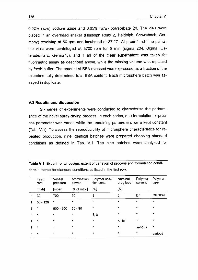
128 Chapter V
0.02% (w/w) sodium azide and 0.05% (w/w) polysorbate 20. The vials were
placed in an overhead shaker (Heidolph Reax 2, Heidolph, Schwabach, Ger¬
many) revolving at 60 rpm and incubated at 37 °C. At predefined time points,
the vials were centrifuged at 3700 rpm for 5 min (sigma 204, Sigma, Os¬
terode/Harz, Germany), and 1 ml of the clear supernatant was taken for
fluorimetric assay as described above, while the missing volume was replaced
by fresh buffer. The amount of BSA released was expressed as a fraction of the
experimentally determined total BSA content. Each microsphere batch was as¬
sayed in duplicate.
V.3 Results and discussion
Six series of experiments were conducted to characterise the perform¬
ance of the novel spray-drying process. In each series, one formulation or proc¬
ess parameter was varied while the remaining parameters were kept constant
(Tab. V.1). To assess the reproducibility of microsphere characteristics for re¬
peated production, nine identical batches were prepared choosing standard
conditions as defined in Tab. V.1. The nine batches were analysed for
Table V.1. Experimental design: extent of variation of process and formulation condi¬
tions.* stands for standard conditions as listed in the first row.
Feed Vessel Atomisation Polymer solu- Nominal Polymer Polymerrate pressure power tion cone. drug load solvent type
[ml/h] [mbar] [%ofmax.] [%] [%]
* 30 700 30 5 5 EF RG503H
1 30-120 *
2 * 500-900 30-90
3 , *
A * * *
C * * *
* * * *
* * * *
5,8
5,15
* * various
* * * various

Chapter V 129
their particle size distribution and six of them further for yield and protein encap¬
sulation.
V.3.1 Product yield
For the batches produced to assess repeatability, the yield amounted to
83.7 ± 4.7% (Fig. V.2 a). Repeatability of the production was satisfactorily re¬
flected by the moderate standard deviation. Yields above 80% by far exceed
values usually obtained in conventional spray-drying equipment for microsphere
batches as small as those prepared here (200 - 300 mg), with values reported
in the literature amounting to 35 - 60% [4,10,11]. In conventional spray-drying
equipment, product is mainly lost through the exhaust air and by adherence to
the cyclone wall. Therefore, the exchange of the pressurised nozzle of a con¬
ventional spray-dryer by an ultrasonic spray-head did not improve the yield [5].
In the novel spray-dryer some product is lost through particle attachment to the
vessel wall and via the vacuum system. However, owing to the narrow-angled
spray-cone of the ultrasonic spray-head and the lack of significant air movement
in the dryer, only a very small fraction of microspheres actually came into con¬
tact with the vessel. Moreover, as only a few litres per hour of air and evapo¬
rated polymer solvent were withdrawn by the vacuum pump, only very few par¬
ticles could have escaped by this way.
Vessel pressure and fluid feed rate did not affect product yield (Fig. V.3),
which for all experiments amounted to 80 - 85%. However, feed rates could only
be varied within a rather narrow range; an unlimited increase in the feed rate
will not be feasible. Under controlled conditions, the liquid leaving the spray-
head's feed capillary spreads on the atomising tip (Fig. V.1 b) and forms a thin
film. Capillary waves are formed on this film excited by the tip's oscillation. The
waves become unstable and their crests are ejected as fine droplets [12,13].
Uncontrolled atomisation occurs when the feed rate becomes too high to allow
for the fluid to evenly spread on the atomisation tip, leading to the formation of
large-scaled, undefined droplets.
Excessive decrease of the vessel pressure causes rapid solvent evapo¬
ration prior to atomisation, so that the solution may become too viscous

130 Chapter V
100
80
TT60
>- 40
20
''"
ï T
i
* » t
-
a
12 3 4 5 6
Batch number
o
'8
B_3o>
C
S<U
10 100 0.1 1
Particle diameter
Figure V.2. Repeatability of microsphere preparation (a,b) and microsphere recovery
(c). a: Product yield Y () and BSA encapsulation efficiency e (•) of six microsphere
batches prepared under identical conditions (standard conditions, Table V.1). The hori¬
zontal lines represent the mean values of Y and e; error bars for e are for repeated
analysis (n = 2). b: Particle size distribution of the six batches detailed in panel A plus a
further three prepared identically (but not analysed with respect to Y and e). c: Particle
size distribution of a batch (prepared at standard conditions), measured once directly in
the collection fluid and once after drying and re-dispersion.

Chapter V 131
400 500 600 700 800 900 1000
p [mbar]
100
— 60
0 30 60 90 120 150
F [ml/h]
Figure V.3. Product yield Y (), BSA encapsulation efficiency e (•) and mean particle
diameter D[4,3] (o) as a function of vessel pressure p (a) and feed rate F (b). All other
conditions were standard conditions (Table V.1). Error bars are for batch-to-batch vari¬
ability (n = 2).

132 Chapter V
Table V.2. Influence of atomisation power on microsphere characteristics. Values are
given as mean of two microsphere batches ± error of the mean. First row gives data for
standard conditions (see Table V.1 ; n = 6, mean ± S.E.M.).
Atomisation
power
Product yield BSA encapsulation
efficiencyMicrosphere meandiameter
D[4,3]
[W (% of maximum)] [%] [%] [nm]
2.4 (30) 83.7+4.7 59.5 ±4.9 18.25 ±1.05
4.8 (60) 72.8 ±9.8 54.2 ±13.7 18.62 + 1.18
7.2 (90) 50.4 ±5.7 54.8 ±4.0 17.54 ±0.64
for spreading and defined spraying. Within the limits mentioned above, an in¬
creased feed rate counteracts excessive solvent evaporation. In addition, with
decreased vessel pressure the risk for vapour bubble formation in the feed tube
increases, resulting in unstable feed conditions and uncontrolled spraying. The
latter effect was observed when the low feed capillary was de-installed and the
spray head's dead volume thereby increased.
Table V.3. Influence of nominal drug load and polymer (RG503H) solution concentra¬
tion on microsphere characteristics. Values are given as mean of two microsphere
batches ± error of the mean. First row gives data for standard conditions (see Table
V.1; n = 6, mean±S.E.M.).
Nominal drugload
Polymer solution
concentration
Product yield BSA encaps.
efficiency
Microspheremean diameter
D[4,3]
[%] [%] [%] [%] [nm]
5 5 83.7+4.7 59.5+4.9 18.25+1.05
15 5 81.4 + 1.0 31.5±0.3 17.49 ±0.23
15 8a 83.8 ±1.7 54.9 ±1.8 29.16 ±1.95
aFor the 8% (w/w) polymer solution, the feed rate was increased from 30 to 60 ml/h.

Chapter V 133
Table V.4. Influence of polymer type and polymer solvent on microsphere characteris¬
tics. Values are given as mean of two microsphere batches ± error of the mean. First
row gives data for standard conditions (see Table V.1 ; n = 6, mean ± S.E.M.).
Polymer Polymer Product yield BSA encaps. Microsphere
type solvent efficiency mean diameter
D[4,3]
[%] [%] [nm]
RG503H EF 83.7±4.7 59.5 ±4.9 18.25 + 1.05
RG503H EA 81.9 ±1.4 60.2 ±1.1 15.08 ±0.81
RG503H DCM 74.1 ±0.1 50.6 ±1.6 23.91 ±0.37
RG502H EF 84.4 ±0.3 74.0 ±1.5 12.74±0.18
R202H EF 68.5 ±1.0 36.6 ±2.0 13.45 ±0.37
RG504 EF 84.6 ±0.5 27.5 ±2.2 20.67 ±0.41
Product yield decreased from above 80% to approximately 50% when
the relative atomisation power was increased from 30 to 90% (Tab. V.2), It
seems that the increased oscillation amplitude impaired the spreading of the
fluid on the atomisation tip of the spray-head. At 60 and 90% relative atomisa¬
tion power, large scaled droplets were ejected from the spray-head and formed
a film on the surface of the collection fluid, which disintegrated into large flakes.
The flaky matter was removed by a 90 urn sieve prior to yield determination.
Increase of the nominal drug load from 5 to 15% did not affect product
yield (Tab. V.3). When the concentration of the polymer solution was increased
from 5 to 8%, the feed rate had to be increased from the standard 30 to 60 ml/h
to achieve effective atomisation and a yield of approximately 84% was obtained
(Tab. V.3). At 30 ml/h, pre-atomisation solvent evaporation led to a pronounced
increase in the solution's viscosity and spray head malfunction.
The polymer and solvent type generally exerted no significant influence
on product yield, except for the particles made from RG503H dissolved in DCM
(74%) and those from R202H in EF (68%, Tab. V.4). In case of RG503H in
DCM, the high vapour pressure of the solvent might again have resulted in pre-

134 Chapter V
atomisation evaporation, leading to uncontrolled atomisation. In fact, flaky mate¬
rial of >90 pm was observed.
V.3.2 Microsphere size and morphology
The reproducibility of the particle size distribution for repeated production
was highly satisfactory. For nine batches of microspheres prepared under iden¬
tical conditions, the size distribution curves were virtually superimposable
(Fig. V.2 b). The mean diameter averaged 18.25 ± 1.05 pm. According to the
10 and 90% undersize diameters, the majority of the particles ranged between
5 and 35 urn. Generally, given a fixed liquid, the droplet size produced by an
ultrasonic spray-head is a function of the exciting frequency [12]. Thus, using a
spray-head with a higher frequency, smaller droplets and therefore particles
could be produced.
Particle size distributions were identical before and after harvesting and
drying of the particles irrespective of the process and formulation conditions
employed (Fig. V.2 c). In fact, only the microspheres prepared of the polymer
RG502H exhibited agglomeration upon harvesting and drying. This finding, al¬
ready observed in a different study [14], might be attributable to water uptake by
the comparatively polar polymer, leading to particle softening and cohesion.
Atomisation power did not have significant influence on particle size
(Tab. V.2). With increasing vessel pressure, the size distribution shifted slightly
but steadily to smaller particle sizes, i.e. from a mean diameter of -23 urn at
500 mbar to -16 pm at 900 mbar (Fig. V.3 a). The droplets ejected from the
spray-head will shrink upon solvent evaporation until a solid layer forms at the
surface, determining the solidifying particle's size. Further solvent removal cre¬
ates pores inside the particles but will not significantly alter their dimension. As
solvent evaporation is slower at higher pressure, the solid layer formation is de¬
layed and particle shrinkage more extended.
With increasing feed rate, a significant shift of the particle size distribution
to larger sizes was observed (Fig. V.3 b). The mean particle diameter increased
from -18 pm at 30 ml/h to -32 pm at 120 ml/h. With increasing feed rate, colli¬
sion and subsequent coalescence of droplets in close vicinity of the atomising
tip becomes more likely, yielding larger particles. Collision between droplets
Chapter V 135
might be diminished by purging the spray-head with air (Fig. V.1 b), so that the
droplets are carried away from the atomising tip more rapidly. Actually, with air
intake, the mean particle size at F = 30 ml/h was reduced from -18 to
-13.5 pm, however at the cost of a reduced yield, amounting to 67% instead of
more than 80% found without air intake. The additional volume of air that has to
be withdrawn by the vacuum pump causes a greater loss of particles via the
exhaust air. In a study where the same type of ultrasonic atomiser was installed
in a standard spray-dryer for the production of BSA-loaded microspheres [5],
much smaller particles of approximately 10 pm mean diameter were found at
comparable experimental conditions (RG503 in DCM, Wp = 5%, F = 120 ml/h).
This might partly be due to the massive air-flow used in their study.
Drug load did not affect particle size while an increase in polymer solu¬
tion concentration from 5 to 8% increased the mean particle size from -18 to
-29 pm (Tab. V.3). Larger particle sizes for more concentrated polymer solu¬
tions are reported both for conventional [11] as well as ultrasonic spray-drying
[5], which has to be attributed to the increased viscosity of the more concen¬
trated solutions. Moreover, for the 8% polymer solution, a bimodal particle size
distribution was obtained; besides the main peak, a small fraction of smaller
particles (1-5 pm) was observed (not shown). We assume that for the more
viscous solution, droplet emission from the capillary waves was accompanied
by the formation of so-called satellite droplets.
When the polymer solvent EF was exchanged by EA or DCM the mean
particle size was slightly lowered (-15 pm) by EA, but increased (-24 urn) by
DCM (Tab. V.4). For the 5% solution in DCM, a bimodal particle size distribution
with a minor peak between 1 and 5 urn was observed (not shown). A possible
explanation for the increase in mean particle diameter with decreasing boiling
point of the polymer solvents (Tb~ 77, 54 and 40°C for EA, EF and DCM, re¬
spectively) could be a more rapid solidification of the microparticles' surface,
which might lead to larger particles as detailed above. Moreover, a more pro¬
nounced evaporation of the solvent prior to atomisation increases the polymer
solution viscosity. Finally, the surface tension and density of the liquid do also
have an impact on the mean droplet size produced by an ultrasonic atomiser
[12]. The bimodal size distribution observed with DCM might again be ascribed

136 Chapter V
to increased solution viscosity due to assumed pre-atomisation solvent evapo¬
ration, resulting in satellite droplets.
c
o
"8£5*^
CD
3o>
c
S
0.1 1 10 100
Particle diameter [nm]
Figure V.4. Dependence of the particle size distribution on the polymer type:
R202H (-•-•), RG502H (....), RG504 (—) and RG503H (—). All other conditions were
standard conditions (Table V.1).
When the polymer RG503H was exchanged by the moderately higher
molecular weight RG504, a slight increase in the mean particle diameter
(Tab. V.4) but almost no change in particle size distribution (Fig. V.4) was
found. However, the low molecular weight polymers RG502H and R202H
yielded smaller mean particle diameters of about 13 urn (Tab. V.4) and a narrow
size distribution (approximately 6 to 23 pm, according to the 10 and 90% under-
size diameters; Fig. V.4). As the molecular weight of RG502H and R202H is
only half of that of RG503H, the reduced viscosity of their solutions might ex¬
plain the observed decrease in particle size.

Chapter V 137
Scanning electron microscopy revealed that the particles produced by
the new method were of spherical shape, but exhibited numerous surface pores
(Fig. V.5 a) and a very porous interior (Fig. V.5 b). Particle porosity may be
caused by fast evaporation of the solvent from the droplets as described above.
However, no significant influence of the vessel pressure on particle porosity
could be observed. Atomisation power and feed rate did not influence morphol¬
ogy and porosity either (pictures not shown). Generally, less diluted polymer so¬
lutions and smaller droplet sizes may reduce porosity.
Figure V.5. SEM micrographs of the microspheres, (a): Surface pores, (b): Porous in¬
terior, (a) made of RG503H, (b) made of RG502H; all other conditions were standard
conditions (Table V.1).
V.3.3 BSA encapsulation efficiency
For the microsphere batches produced under identical conditions, the
mean BSA encapsulation efficiency was 59.5% and the standard error of the
mean 4.9% (Fig. V.2 a). This contrasts to the 80-90% BSA encapsulation effi¬
ciency reported for ultrasonic atomisation into a flow of warm air [5], The mod¬
erate encapsulation efficiency for BSA produced by our new spray-drying
method is likely due to BSA loss into the aqueous solution wherein the particles

138 Chapter V
were collected. Such loss may be reduced when a non-solvent for the com¬
pound to be encapsulated is used as collection fluid, which is subject of ongoing
studies.
The process parameters of vessel pressure, feed rate (Fig. V.3) and at¬
omisation power (Tab. V.2) did not significantly affect the BSA encapsulation
efficiency, which generally varied between 50 and 60%.
When the nominal BSA load of the microparticles was increased from 5%
to 15%, the encapsulation efficiency dropped from -60% to -32% (Tab. V.3).
As detailed above, loss of BSA will mainly occur through partitioning into the
aqueous collection bath, which is more pronounced for higher nominal loadings
due to the higher concentration gradient between the microparticles and the
surrounding fluid. However, when microparticles with a nominal drug load of
15% were produced from an 8% rather than 5% polymer solution, the encapsu¬
lation efficiency re-increased to approximately 55% (Tab. V.3). A more concen¬
trated polymer solution may produce less porous particles and the higher vis¬
cosity of the solution will limit BSA droplet coalescence in the emulsion sprayed,
both limiting BSA losses.
The use of EA instead of EF as polymer solvent did not affect BSA en¬
capsulation (-60%), whereas DCM reduced the encapsulation efficiency (-51%,
Tab. V.4). The different polymer types (dissolved in EF) affected BSA encapsu¬
lation efficiency in the following order: RG502H > RG503H » R202H > RG504,
with a satisfactory 74% efficiency found for RG502H (Tab. V.4). This order cor¬
relates with the polarity of the polymers, which seems reasonable as increased
polymer polarity affords stronger protein-polymer interactions thereby improving
protein encapsulation [15].
V.3.4 In vitro BSA release
For all batches of microspheres prepared so far, the burst release (BSA
release within the first 24 h) was unacceptably high exceeding 50% of total
dose. The strongly porous particles may have readily taken up water from the
release buffer, resulting in quick dissolution of the encapsulated BSA [16,17].
Atomisation power, feed rate and vessel pressure as well as the solvent type

Chapter V 139
100
wP = 5% wP = 5% wP = 8% wP = 8%
LD = 5% LD = 15% LD= 15% LD = 5%
100
10 15
Time [days]
25
Figure V.6. BSA release from the microspheres, (a)- 24 h burst release dependant on
polymer solution concentration wP and nominal drug load LD. At least two batches of
each microsphere formulation were examined, represented by the double/triple bars;
error bars are for repeated analysis (n = 2). (b). BSA release from microspheres pre¬
pared at wP = 5% (a) and wP = 8% (•); all other conditions were standard conditions
(Table V.1). Error bars are for batch-to-batch variability (n = 2).

140 Chapter V
did not significantly influence BSA burst (data not shown) like they did not affect
porosity. Increasing nominal drug Ld from 5% to 15% augmented the average
burst release from -58% to -68%, while an increase in the polymer solution
concentration wP from 5% to 8% (at LD = 15%) re-decreased the average burst
to approximately 56% (Fig. V.6 a). Therefore, three additional microsphere
batches were produced at wP = 8% and the standard LD = 5%. For these
batches, average BSA burst release strongly diminished to approximately 16%
(Fig. V.6 a). The particles made of the more concentrated polymer solutions will
feature less pores, thereby limiting instantaneous BSA dissolution.
The microsphere batches exhibiting high burst releases showed almost
no further release of BSA during the following 21 days (Fig. V.6 b). Such re¬
lease profiles are not uncommon in literature [18,19] and attributed to non-
covalent protein aggregation [18] and protein adsorption on the polymer back¬
bone [20]. It was found that protein exposure to oil/water or air/water interfaces
combined with high shear force led to protein aggregation [21,22]. In our ex¬
periments, the dispersion of the aqueous BSA solution in the organic polymer
solution by ultrasonication could have led to such aggregation. Milder dispersion
conditions (e.g. reduced ultrasonic intensity) and the use of stabilisers [23] may
reduce the detrimental effect.
The microspheres prepared at wP = 8% and LD = 5% showed a slightly
more sustained release from a mean 16.1% of total BSA dose released on day
1 to a mean of 22.3% released on day 21. The higher viscosity of the more con¬
centrated polymer solution might have reduced the shear forces acting upon the
protein during ultrasonic dispersion.
V.4 Conclusions
In this work, ultrasonic atomisation into reduced pressure atmosphere
was evaluated for the encapsulation of the model protein BSA in PLGA micro¬
spheres. Simple particle recovery and vacuum instead of hot air for drying the
particles makes this method well suited for aseptic microsphere preparation as
compared to conventional spray-drying. High particle yields but solely moderate
BSA encapsulation efficiencies were obtained. The majority of particles was

Chapter V 141
very porous and exhibited an unacceptably high BSA burst release. However,
24 h bursts of particles prepared from more concentrated polymer solutions
were strongly decreased. Further research will be directed at non-aqueous col¬
lection fluids to improve encapsulation of water-soluble compounds and to
smaller and less porous particles.
Acknowledgements
The authors would like to thank Dr. Ernst Wehrli, Laboratory of Electron
Microscopy, ETH Zürich for the preparation of the scanning electron micro¬
graphs. We also thank Stefan Raduner, Alexandra Honegger, Michael Ulrich
and René Bemsel for their valuable technical assistance and advice.
References
[1] S. Cohen, T. Yoshioka, M. Lucarelli, L.H. Hwang, R. Langer, Controlled
delivery systems for proteins based on poly(lactic/glycolic acid) micro¬
spheres, Pharm. Res. 8 (1991) 713-720.
[2] C. Erni, C, Suard, S. Freitas, D. Dreher, H.P. Merkle, E. Walter, Evalua¬
tion of cationic solid lipid microparticles as synthetic carriers for the tar¬
geted delivery of macromolecules to phagocytic antigen-presenting cells,
Biomaterials 23 (2002) 4667-4676.
[3] Y.F. Maa, P.A. Nguyen, K. Sit, C.C. Hsu, Spray-drying performance of a
bench-top spray dryer for protein aerosol powder preparation, Biotech.
Bioeng. 60 (1998) 301-309.
[4] P. Johansen, H.P. Merkle, B. Gander, Technological considerations re¬
lated to the up-scaling of protein microencapsulation by spray-drying,
Eur. J. Pharm. Biopharm. 50 (2000) 413-417.
[5] B. Bittner, T. Kissel, Ultrasonic atomization for spray drying: a versatile
technique for the preparation of protein loaded biodegradable micro¬
spheres, J. Microencapsulation 16 (1999) 325-341.

142 Chapter V
[6] D. Mohr, M. Wolff, T. Kissel, Gamma irradiation for terminal sterilization
of 17ß-estradiol loaded poly-(D.L-lactide-co-glycolide) microparticles,
J. Control. Release 61 (1999) 203-217.
[7] C. Dirix, H. Kamp, A. Sam, A process for the preparation of biologically
active material-containing polymeric microcapsules, European Patent
0 556 917 A1, 1993.
[8] C.B. Felder, M.J. Blanco-Prfeto, J. Heizmann, H.P. Merkle, B. Gander,
Ultrasonic atomisation and subsequent polymer desolvation for peptide
and protein microencapsulation into biodegradable polyesters, J. Micro¬
encapsulation, in press.
[9] C. Thomasin, H.P. Merkle, B. Gander, Drug Microencapsulation by
PLA/PLGA coacervation in the light of thermodynamics. 2. Parameters
determining microsphere formation, J. Pharm. Sei. 87 (1988) 269-275.
[10] F. Pavanetto, B. Conti, I. Genta, P. Giunchedi, Solvent evaporation, sol¬
vent extraction and spray drying for polylactide microsphere preparation,
Int. J. Pharm. 84 (1992) 151-159.
[11] F. Pavanetto, I. Genta, P. Giunchedi, B. Conti, Evaluation of spray drying
as a method for polylactide and polylactide-co-glycolide microsphere
preparation, J. Microencapsulation 10 (1993) 487-497.
[12] R.J. Lang, Ultrasonic atomization of liquids, J. Acoust. Soc. Am. 34
(1962)6-8.
[13] D.D. Lobdell, Particle size-amplitude relations for the ultrasonic atomizer,
J. Acoust. Soc. Am. 43 (1968) 229-231.
[14] S. Freitas, A. Walz, H.P. Merkle, B. Gander, Solvent extraction employ¬
ing a static micromixer: a simple, robust and versatile technology for the
microencapsulation of proteins, J. Microencapsulation 20 (2003) 67-85.
[15] H. Marchais, F. Boury, C. Damgé, J.E. Proust, J.P. Benoit, Formulation
of bovine serum albumin loaded PLGA microspheres. Influence of the
process variables on the loading and in vitro release, STP Pharma Sei., 6
(1996)417-423.
[16] K.F. Pistel, T. Kissel, Effects of salt addition on the microencapsulation of
proteins using W/O/W double emulsion technique, J. Microencapsulation
17(2000)467-483.
Chapter V 143
[17] Y.Y. Yang, T.S. Chung, N.P. Ng, Morphology, drug distribution and in vi¬
tro release profiles of biodegradable polymeric microspheres containing
protein fabricated by double emulsion solvent extraction/evaporation
method, Biomaterials 22 (2001) 231-241.
[18] H.K. Kim, T.G. Park, Microencapsulation of human growth hormone
within biodegradable polyester microspheres: protein aggregation stabil¬
ity and incomplete release mechanism, Biotech. Bioeng. 65 (1999) 659-
667.
[19] Y.Y. Yang, H.H. Chia, T.S. Chung, Effect of preparation temperature on
the characteristics and release profiles of PLGA microspheres containing
protein fabricated by double-emulsion solvent extraction/evaporation
method, J. Control. Release 69 (2000) 81-96.
[20] G. Crotts, T-G. Park, Stability and release of bovine serum albumin en¬
capsulated within poly(D,L-lactide-co-glycolide) microparticles, J. Control.
Release 44 (1997) 123-134.
[21] M. van de Weert, J. Hoechstetter, W.E. Hennink, D.J. Crommelin, The
effect of a water/organic solvent interface on the structural stability of ly¬
sozyme, J. Control. Release 68 (2000) 351-359.
[22] Y.F. Maa, C.C. Hsu, Protein denaturation by combined effect of shear
and air-liquid interface, Biotech. Bioeng., 54 (1997) 503-512.
[23] F.R. Kang, J. Singh, Conformational stability of a model protein (bovine
serum albumin) during primary emulsification process of PLGA micro¬
spheres synthesis, Int. J. Pharm. 260 (2003) 149-156.

144 Chapter V
Seite Leer /
Blank leaf

Discussion and outlook 145
Discussion and outlook
The objective of the present work was to develop microencapsulation
processes that are well suited for (i) the aseptic preparation of drug-loaded bio¬
degradable microspheres, typically made from PL(G)A, and (ii) the scaling-up of
the laboratory process to a pilot-scale process. The second aspect was not fur¬
ther investigated in the context of this study, because it would have caused rela¬
tively large investment costs; nonetheless, scaling-up was taken into considera¬
tion in the design of the new processes. At the beginning of the processes de¬
sign, some critical criteria for enabling aseptic manufacturing were defined.
They included:
(i) avoidance of open vessels to isolate the processed materials from the
environment
(ii) feasibility of continuous processing and minimisation of manual manipu¬
lation
(iii) use of simple, sterilisable and easy-to-clean equipment
(iv) avoidance of warm drying air and pressurised air for liquid atomisation
(as needed in conventional spray-drying)
Various process and formulation parameters were studied in the devel¬
oped processes, and their influence on microsphere size distribution, morphol¬
ogy, protein loading and protein release were assessed. Bovine serum albumin
encapsulated in PL(G)A was employed as a model system. The developed
processes included: (i) a contact-free continuous emulsification in a novel ultra¬
sonic flow-through cell for preparing primary W/O-emulsions that can be further
processed into microspheres, or for preparing OA/V-emulsions for direct fabrica¬
tion of nanoparticles; (ii) a solvent extraction process for microsphere prepara¬
tion that is based on micro-scale flow in a static micromixer; (iii) an ultrasonic
atomisation process into low pressure atmosphere for microsphere preparation
by spray-drying.
The continuous ultrasonic flow-through cell proved to be well suited to
prepare both oil-in-water and water-in-oil emulsions. The droplet size of the dis¬
perse phase was effectively reduced by two or more orders of magnitude. The
reproducibility of the resulting droplet size distribution was highly satisfactory.
Emulsions of a BSA solution in a solution of PLGA prepared by the flow-through

146 Discussion and outlook
ultrasonic cell were successfully further processed into BSA-loaded micro¬
spheres. Polymeric nanoparticles were prepared by oil-in-water emulsification
and subsequent solvent extraction. However, not being the main focus of this
thesis, this method of nanoparticle preparation was not further investigated, al¬
though various features appear highly attractive for further exploration such as
the avoidance of PVA for use as stabiliser, the possibility to entrap proteins and
other drugs, the feasibility to obtain sterile nanoparticles or the processing of
other materials such as lipids or other polymers.
The particular benefit of this method to produce emulsions resides in the
contact-free use of ultrasound. High-shear homogenisers of the Polytron®-type
are difficult to clean and sterilise and thus constitute an important source of
product contamination. Direct sonication by immersion of a sonotrode in the
emulsion may lead to the emission of metallic particles or ions by action of cavi¬
tation. Moreover, both of these set-ups are inconvenient for fully segregating the
processed materials from the environment. In contrast, the here developed flow-
through ultrasonic cell features contact-free action and simple exchange and
sterilisation of the parts in contact with the product, which both strongly facilitate
aseptic processing.
The present flow-through cell has its limitations with respect to the power
transferred to the emulsion. Scaling-up the process by installation of a manifold
of parallel glass tubes in the cell would probably improve largely the energetic
efficiency, as the ratio of energy expended for exciting the apparatus to that ac¬
tually resulting in emulsification would be enhanced. However, it would be de¬
sirable to improve also the absolute power input to yield even finer emulsions.
BSA-loaded PL(G)A microspheres were reproducibly prepared employ¬
ing the IMM multilamination micromixer. The mixer offers comfortable control of
the microsphere size by simply varying the flow rates of extraction fluid and
polymer solution and robustness towards changes in microsphere formulation
parameters, which leaves size distributions essentially unaffected. Scale-up
should be easily achievable by using a sufficient number of mixers in parallel
("number-up"). The mixer's small size and simple design facilitate cleaning, ster¬
ilisation and assembling, which makes the mixer attractive for aseptic micro¬
sphere preparation. We were able to demonstrate that the combined used of

Discussion and outlook 147
the ultrasonic flow-through cell and micromixer yielded microspheres that
passed a simplified sterility test.
The IMM micromixer wins over conventional vessel/stirrer set-ups, which
offer poor control of microsphere size. Moreover, scale-up often is delicate and
mostly achievable only via trial and error. Classical tube-installed static mixers
are comparable to the micromixer in terms of microsphere size control and
scalability, but they are difficult to clean and thus not well suited for aseptic
processing. Extrusion through microdevices or membranes offers much better
control of the microsphere size than the IMM micromixer, but suffer generally
from low productivity as very slow flow velocities are required. Further, cleaning
and sterilisation of extrusion-operated microdevices is difficult, because of the
very small size and complex geometries.
The most significant drawback in using the IMM micromixer for micro¬
sphere preparation resides in the considerable polydispersity of the resulting
particles, despite the seemingly well-defined, laminar flow regime inside the
mixer. This may possibly be ascribed to non-optimal design of the mixer's outlet
slit that exhibits an abrupt transition from a wide slit at the level of the channel
array to a very fine tube towards the mixer's outlet. This transition is likely to
transform the initially well-defined fluid lamellae into a turbulent chaotic flow.
Ultrasonic atomisation into a reduced pressure atmosphere allowed us to
reproducibly prepare BSA-loaded microspheres, which, however, were rather
polydisperse. The use of rather concentrated polymer solutions is required to
yield particles of acceptable porosity and burst release. Very satisfactory prod¬
uct yields were obtained, even for very small batch sizes, exceeding by far
those found with conventional spray-drying.
The novel spray-drying process offers considerable advantages over
conventional spray-drying using warm-air and pressurized air-operated nozzles,
if aseptic preparation is considered. The novel procedure obviates the need to
sterilise large streams of warm drying air. The gentle spray produced by the
ultrasonic atomiser allows the drying microspheres to settle slowly into a liquid
bath, which can be comfortably withdrawn from the apparatus. Therefore, mi¬
crosphere harvesting requires only minimum manual interference while conven¬
tional spray-drying often requires manual rinsing of the equipment to recover
148 Discussion and outlook
sufficient amounts of the microspheres, which is unacceptable for aseptic proc¬
essing.
Ultrasonic atomisation into a reduced pressure atmosphere tended to
produce rather porous microspheres, which could be improved by using more
concentrated polymer solutions and suitable polymer solvents. The choice of
the collection fluid has to be done with care to avoid dissolution and loss of en¬
trapped material. Finally, the mean particle size can only be controlled by the
atomiser's operating frequency
In summary, the novel technologies developed in the present study rep¬
resent promising approaches towards aseptic production of drug-loaded biode¬
gradable microspheres. However, the sterility testing performed in this study is
by no means sufficient to ensure product sterility on a GMP-level. Especially,
the method to dissolve/disintegrate the microspheres to get access to possible
encapsulated microbial contaminants would require thorough validation to ex¬
clude erroneously positive sterility results by harming the entrapped microbes.
The encapsulation of peptides and proteins necessitates stabilisation measures
to protect them from the harsh conditions during microsphere preparation and
degradation (aqueous-organic interfaces combined with shear forces, pH-
change upon degradation) and prevent their adsorption to the matrix-forming
polymer. Like in many other studies reported in literature, incomplete protein
release from the microspheres was observed in the present study and ascribed
to protein adsorption and aggregation. However, the required stabilisation
measures do not solely depend on the processing conditions, but also strongly
on the nature of the encapsulated compound, matrix material(s), microsphere
formulation and solvent type. Thus, any stabilisation measure requires case-
specific optimisation. Defining stabilisation strategies for the newly developed
techniques was therefore beyond the scope of this work.

Curriculum Vitae, Publications 149
Curriculum Vitae
05/1993
06/1993-08/1994
10/1994-04/2000
04/2000
05/2000-01/2004
Publications
S. Freitas, G. Hieischer, H.P. Merkle, B. Gander, Continuous contact- and con¬
tamination-free ultrasonic emulsification - a useful tool for pharmaceutical
development and production, Ultrasonics Sonochem., 13 (2006) 76-85.
S. Freitas, H.P. Merkle, B. Gander, Microencapsulation by solvent extrac¬
tion/evaporation: reviewing the state of the art of microsphere preparation
process technology, J. Control. Release, 102 (2005) 313-332.
S. Freitas, B. Rudolf, H.P. Merkle, B. Gander, Flow-through ultrasonic emulsifi¬
cation combined with static micromixing for aseptic production of micro¬
spheres by solvent extraction, Eur. J. Pharm. Biopharm., 61 (2005) 181-187
S. Freitas, H.P. Merkle, B. Gander, Solvent extraction employing a static mi¬
cromixer: a simple, robust and versatile technology for the microencapsula¬
tion of proteins, J. Control. Release 95 (2004) 185-195.
Graduation from high-school "Johannes-Althusius-
Gymnasium", Emden, Germany
Alternative service at an home for the aged, Emden,
Germany
Undergraduate studies in chemical engineering at
Technische Universität Clausthal, Clausthal-Zeller-
feld, Germany and ETH Zürich, Switzerland
Graduation ("summa cum laude") as chemical
engineer (Dipl.-Ing.)
Postgraduate studies at the Drug Formulation and
Delivery Group, Institute of Pharmaceutical Sciences,
ETH Zürich under supervision of Prof. H.P. Merkle
and PD Dr. B. Gander

150 Curriculum Vitae, Publications
S. Freitas, A. Walz, H.P. Merkle, B. Gander, Ultrasonic atomisation into re¬
duced pressure atmosphere - envisaging aseptic spray-drying for microen¬
capsulation, J. Microencapsulation 20 (2003) 67 - 85.
C. Erni, C. Suard, S. Freitas, D. Dreher, H.P. Merkle, E. Walter, Evaluation of
cationic solid lipid microparticles as synthetic carriers for the targeted delivery
of macromolecules to phagocytic antigen-presenting cells, Biomaterials 23
(2002) 4667 - 4676.
F. Lode, S. Freitas, M. Mazzotti, M. Morbidelli, Sorptive and catalytic properties
of partially sulfonated resins, Ind. Eng. Chem. Res. 43 (2004) 2658 - 2668.
Patents
S. Freitas, B. Gander, N. Lehmann, Verfahren und Durchflusszelle zur kontinu¬
ierlichen Bearbeitung von fliessfähigen Zusammensetzungen mittels Ultra¬
schall, German patent application, 2002.

Acknowledgements 151
Acknowledgements
In the first place, I would like to sincerely thank Prof. Hans P. Merkle for
giving me the opportunity to do my Ph.D. in his group, for his help, support and
for the corrections of my thesis.
Very many thanks go to Prof. Bruno Gander, my co-referee and supervi¬
sor, for his steady support, encouragement, for fruitful and critical discussions
and corrections of my thesis. Many thanks in addition, dear Bruno, for caring
about my sportive performance, for your imperturbably good mood and for be¬
ing a very close friend.
Many thanks go to Prof. Jean-Pierre Benoit for agreeing to be my second
co-referee, for discussions and his interest in my work.
I am very grateful to Dr. Hielscher of Dr. Hielscher GmbH for constructing
the ultrasonic flow-through cell, his constant support and manifold discussions.
I am thankful to Prof. Steffen Hardt, Prof. Volker Hessel and Dr. Bernd
Werner of the Institut für Mikrotechnik Mainz GmbH for their support in the field
of micromixer technology, for generous donation of equipment, for giving me the
opportunity to work for several weeks at the IMM and for their input and discus¬
sions.
Many thanks to the staff of the Universität Zürich glassworks for turning
my many weird ideas into functioning reality.
A very heartly thank-you to Kathrin and Michael with whom I shared a lab
as well as to all other members of the group, namely Michael, Lars, Annette,
Elke, Lukas, Vera, Stefan, Rachel, Samantha, Christina, Uta, Ruth and Lorenz
for the warm and friendly atmosphere in the group, for shared parties, hiking
trips, cinema evenings, ski excursions,... Despite all ups and downs I spent
wonderful years with you all! Special thanks to Michael and Kathrin for their

152 Acknowledgements
magic tricks (making 500g of chocolate-coated almonds disappear in minutes)
and for aiding me in high-glycaemic food stock-keeping.
Special thanks
Countless thanks and hugs to Ulla for her love, many, many encourage¬
ments and especially for her endless patience during the tough time of finishing
writing the thesis.
Many, many thanks to my parents as well as to Chrysantha and Ayres for
support, encouragements and love.
Finally, thanks to my flat-mates Anna-Ursina, Barbara and Vinh for the
joyful days we spent together.