right angle drives Inch and Metric...
12
ANGLgear ® right angle drives Inch and Metric Series “The Original Right Angle Gear Drive” Made in the U.S.A.
Transcript of right angle drives Inch and Metric...

ANGLgear®
right angle drivesInch and Metric Series
“The Original Right Angle Gear Drive”Made in the U.S.A.

800-713-6170 • www.andantex.com • [email protected]
1
Intro to ANGLgear Inch & Metric Series pg. 2-3
2 Flange Units, Inch Series pg. 4
3 Flange Units, Inch Series pg. 5
Selection & Ordering Information, pg. 6Inch Series
2 Flange Units, Metric Series pg. 7
3 Flange Units, Metric Series pg. 8
Selection & Ordering Information, pg. 9Metric Series
Special Units Inch & Metric Series pg. 10
INDEX
800-713-6170 • www.andantex.com • [email protected]
2
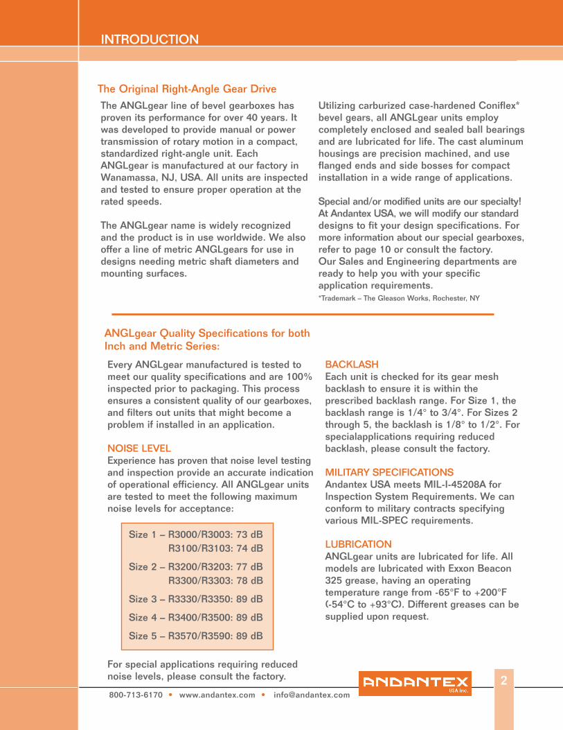
The ANGLgear line of bevel gearboxes has proven its performance for over 40 years. It was developed to provide manual or power transmission of rotary motion in a compact, standardized right-angle unit. Each ANGLgear is manufactured at our factory in Wanamassa, NJ, USA. All units are inspected and tested to ensure proper operation at the rated speeds.
The ANGLgear name is widely recognized and the product is in use worldwide. We also offer a line of metric ANGLgears for use in designs needing metric shaft diameters and mounting surfaces.
Utilizing carburized case-hardened Coniflex* bevel gears, all ANGLgear units employ completely enclosed and sealed ball bearings and are lubricated for life. The cast aluminum housings are precision machined, and useflanged ends and side bosses for compact installation in a wide range of applications.
Special and/or modified units are our specialty! At Andantex USA, we will modify our standard designs to fit your design specifications. For more information about our special gearboxes, refer to page 10 or consult the factory.Our Sales and Engineering departments are ready to help you with your specific application requirements.*Trademark – The Gleason Works, Rochester, NY
The Original Right-Angle Gear Drive
INTRODUCTION
Every ANGLgear manufactured is tested to meet our quality specifications and are 100% inspected prior to packaging. This process ensures a consistent quality of our gearboxes, and filters out units that might become aproblem if installed in an application.
NOISE LEVELExperience has proven that noise level testing and inspection provide an accurate indication of operational efficiency. All ANGLgear units are tested to meet the following maximum noise levels for acceptance:
For special applications requiring reduced noise levels, please consult the factory.
BACKLASHEach unit is checked for its gear mesh backlash to ensure it is within the prescribed backlash range. For Size 1, the backlash range is 1/4° to 3/4°. For Sizes 2 through 5, the backlash is 1/8° to 1/2°. For specialapplications requiring reduced backlash, please consult the factory.
MILITARY SPECIFICATIONSAndantex USA meets MIL-I-45208A for Inspection System Requirements. We can conform to military contracts specifying various MIL-SPEC requirements.
LUBRICATIONANGLgear units are lubricated for life. All models are lubricated with Exxon Beacon 325 grease, having an operating temperature range from -65°F to +200°F (-54°C to +93°C). Different greases can be supplied upon request.
ANGLgear Quality Specifications for bothInch and Metric Series:
Size 1 – R3000/R3003: 73 dB R3100/R3103: 74 dB
Size 2 – R3200/R3203: 77 dB R3300/R3303: 78 dB
Size 3 – R3330/R3350: 89 dB
Size 4 – R3400/R3500: 89 dB
Size 5 – R3570/R3590: 89 dB

800-713-6170 • www.andantex.com • [email protected]
3
BEVEL GEARSAll gears in the ANGLgear product line are cut using the Gleason Generating System to a AGMA Quality Class 9. This system develops straight bevel Coniflex tooth profiles, which are crowned at the center of the tooth. This allows for better tooth meshing, and operating pitchline velocities of over 1000 feet per minute. All gears are then carburized case hardened to ensure a long operating life.
BEARINGSThere are four ball bearings in each ANGLgear unit. Each bearing is packed with Exxon Beacon 325 Grease and sealed with two Buna-N seals. The bearings are lubricated for life. Special seals such as Viton and Teflon can be provided for high temperature applications.
HOUSINGThe housings are aluminum alloy castings. Each housing is precision machined on our CNC machining center and then coated with a chemical film to protect the material. We can offer special materials and coatings for further protection in corrosive environments, and special machining for precision mounting and alignment.
SHAFTSThe shaft material for Sizes 1, 2 and 3 is #416 stainless steel. **On 2:1 models, the pinion shaft is cadmiumplated carbon steel. For Sizes 4 and 5, the shaft material is black-oxide carbon steel. We can offer a variety of materials and treatments to meet your design specifications. Shafts can be provided with special extensions (with flats, splines, holes, etc.) and/or specific lengths upon request.
ANGLgear Quality Specifications:
Grease Lubricated
Hardened Coniflex Straight Bevel Gears
Universal Mounting Positions
Double Sealed Ball Bearings
Cast Aluminum Housings
Stainless Steel Shafts Type 416**
800-713-6170 • www.andantex.com • [email protected]
4
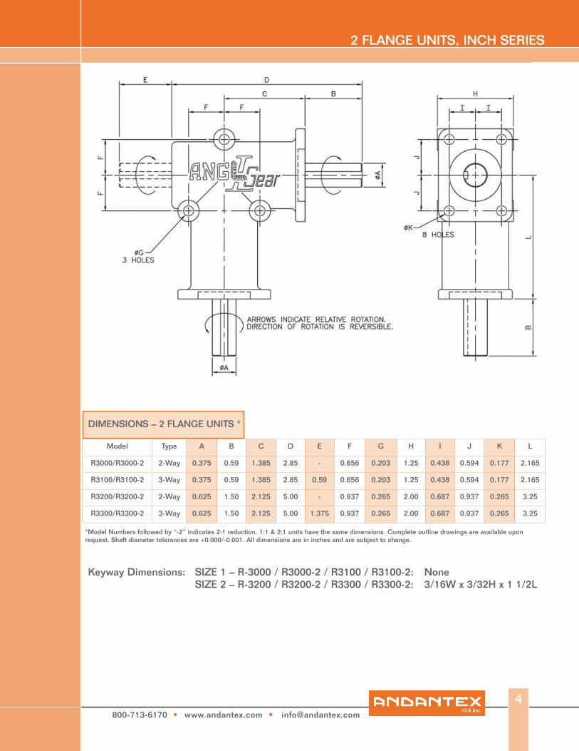
2 FLANGE UNITS, INCH SERIES
Model Type A B C D E F G H I J K L
R3000/R3000-2 2-Way 0.375 0.59 1.385 2.85 - 0.656 0.203 1.25 0.438 0.594 0.177 2.165
R3100/R3100-2 3-Way 0.375 0.59 1.385 2.85 0.59 0.656 0.203 1.25 0.438 0.594 0.177 2.165
R3200/R3200-2 2-Way 0.625 1.50 2.125 5.00 - 0.937 0.265 2.00 0.687 0.937 0.265 3.25
R3300/R3300-2 3-Way 0.625 1.50 2.125 5.00 1.375 0.937 0.265 2.00 0.687 0.937 0.265 3.25
DIMENSIONS – 2 FLANGE UNITS *
*Model Numbers followed by “-2” indicates 2:1 reduction. 1:1 & 2:1 units have the same dimensions. Complete outline drawings are available upon request. Shaft diameter tolerances are +0.000/-0.001. All dimensions are in inches and are subject to change.
Keyway Dimensions: None3/16W x 3/32H x 1 1/2L
SIZE 1 – R-3000 / R3000-2 / R3100 / R3100-2: SIZE 2 – R-3200 / R3200-2 / R3300 / R3300-2:

800-713-6170 • www.andantex.com • [email protected]
3 FLANGE UNITS, INCH SERIES
Model Type A B C D E F G H I J K L M
R3003/R3003-2 2-Way 0.375 0.59 1.385 3.36 - 0.656 0.209 1.25 0.438 0.594 0.177 2.165 0.656
R3103/R3103-2 3-Way 0.375 0.59 1.385 3.36 0.59 0.656 0.209 1.25 0.438 0.594 0.177 2.165 0.656
R3203/R3203-2 2-Way 0.625 1.50 2.125 5.75 - 0.937 0.265 2.00 0.687 0.937 0.265 3.25 0.937
R3303/R3303-2 3-Way 0.625 1.50 2.125 5.75 1.50 0.937 0.265 2.00 0.687 0.937 0.265 3.25 0.937
R3330/R3330-2 2-Way 0.75 2.00 3.00 8.00 - 1.50 0.344 3.00 1.125 1.50 0.344 5.00 1.50
R3350/R3350-2 3-Way 0.75 2.00 3.00 8.00 2.00 1.50 0.344 3.00 1.125 1.50 0.344 5.00 1.50
R3400/R3400-2 2-Way 1.00 2.75 3.25 9.25 - 1.75 0.406 4.00 1.50 1.50 0.406 6.00 2.75
R3500/R3500-2 3-Way 1.00 2.75 3.25 9.25 2.75 1.75 0.406 4.00 1.50 1.50 0.406 6.00 2.75
R3570 2-Way 1.00 2.75 3.25 9.25 - 1.75 0.406 4.00 1.50 1.50 0.406 6.00 2.75
R3590 3-Way 1.00 2.75 3.25 9.25 2.75 1.75 0.406 4.00 1.50 1.50 0.406 6.00 2.75
DIMENSIONS – 3 FLANGE UNITS *
* Model Numbers followed by “-2” indicates 2:1 reduction. 1:1 & 2:1 units have the same dimensions. Complete outline drawings are available upon request. Shaft diameter tolerances are +0.000/-0.001. All dimensions are in inches and are subject to change.
Keyway Dimensions: None3/16W x 3/32H x 1 1/4L3/16W x 3/32H x 1 1/4L1/4W x 1/8H x 2L1/4W x 1/8H x 2L
SIZE 1 – R3003 / R3003-2 / R3103 / R3103-2:SIZE 2 – R3203 / R3203-2 / R3303 / R3303-2: SIZE 3 – R3330 / R3330-2 / R3350 / R3350-2: SIZE 4 – R3400 / R3400-2 / R3500 / R3500-2:SIZE 5 – R3570 / R3590:
5
800-713-6170 • www.andantex.com • [email protected]
6
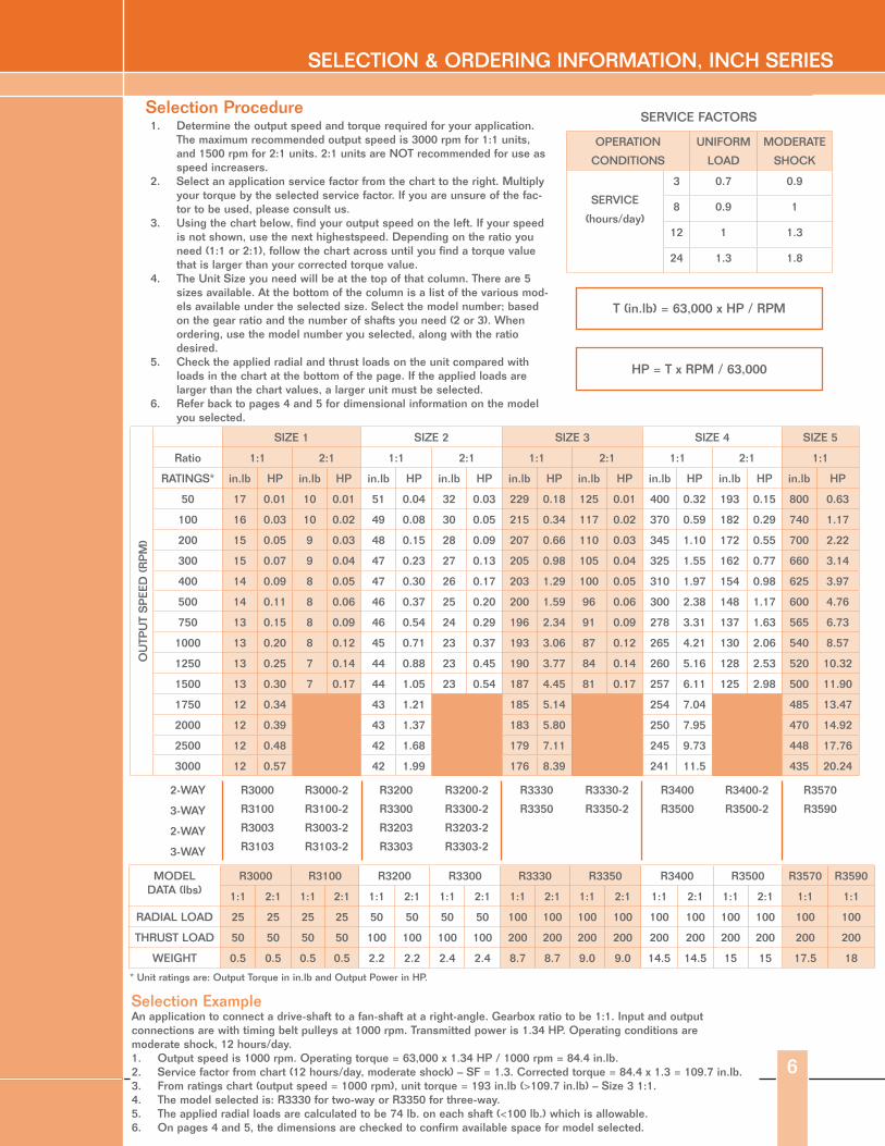
SELECTION & ORDERING INFORMATION, INCH SERIES
1. Determine the output speed and torque required for your application. The maximum recommended output speed is 3000 rpm for 1:1 units, and 1500 rpm for 2:1 units. 2:1 units are NOT recommended for use as speed increasers.
2. Select an application service factor from the chart to the right. Multiply your torque by the selected service factor. If you are unsure of the fac-tor to be used, please consult us.
3. Using the chart below, find your output speed on the left. If your speed is not shown, use the next highestspeed. Depending on the ratio you need (1:1 or 2:1), follow the chart across until you find a torque value that is larger than your corrected torque value.
4. The Unit Size you need will be at the top of that column. There are 5 sizes available. At the bottom of the column is a list of the various mod-els available under the selected size. Select the model number; based on the gear ratio and the number of shafts you need (2 or 3). When ordering, use the model number you selected, along with the ratio desired.
5. Check the applied radial and thrust loads on the unit compared with loads in the chart at the bottom of the page. If the applied loads are larger than the chart values, a larger unit must be selected.
6. Refer back to pages 4 and 5 for dimensional information on the model you selected.
Selection Procedure
OPERATION
CONDITIONS
UNIFORM
LOAD
MODERATE
SHOCK
SERVICE
(hours/day)
3 0.7 0.9
8 0.9 1
12 1 1.3
24 1.3 1.8
SERVICE FACTORS
T (in.lb) = 63,000 x HP / RPM
HP = T x RPM / 63,000
SIZE 1 SIZE 2 SIZE 3 SIZE 4 SIZE 5
Ratio 1:1 2:1 1:1 2:1 1:1 2:1 1:1 2:1 1:1
RATINGS* in.lb HP in.lb HP in.lb HP in.lb HP in.lb HP in.lb HP in.lb HP in.lb HP in.lb HP
50 17 0.01 10 0.01 51 0.04 32 0.03 229 0.18 125 0.01 400 0.32 193 0.15 800 0.63
100 16 0.03 10 0.02 49 0.08 30 0.05 215 0.34 117 0.02 370 0.59 182 0.29 740 1.17
200 15 0.05 9 0.03 48 0.15 28 0.09 207 0.66 110 0.03 345 1.10 172 0.55 700 2.22
300 15 0.07 9 0.04 47 0.23 27 0.13 205 0.98 105 0.04 325 1.55 162 0.77 660 3.14
400 14 0.09 8 0.05 47 0.30 26 0.17 203 1.29 100 0.05 310 1.97 154 0.98 625 3.97
500 14 0.11 8 0.06 46 0.37 25 0.20 200 1.59 96 0.06 300 2.38 148 1.17 600 4.76
750 13 0.15 8 0.09 46 0.54 24 0.29 196 2.34 91 0.09 278 3.31 137 1.63 565 6.73
1000 13 0.20 8 0.12 45 0.71 23 0.37 193 3.06 87 0.12 265 4.21 130 2.06 540 8.57
1250 13 0.25 7 0.14 44 0.88 23 0.45 190 3.77 84 0.14 260 5.16 128 2.53 520 10.32
1500 13 0.30 7 0.17 44 1.05 23 0.54 187 4.45 81 0.17 257 6.11 125 2.98 500 11.90
1750 12 0.34 43 1.21 185 5.14 254 7.04 485 13.47
2000 12 0.39 43 1.37 183 5.80 250 7.95 470 14.92
2500 12 0.48 42 1.68 179 7.11 245 9.73 448 17.76
3000 12 0.57 42 1.99 176 8.39 241 11.5 435 20.24
OU
TPU
T S
PEE
D (
RP
M)
2-WAY R3000
R3100
R3003
R3103
R3000-2
R3100-2
R3003-2
R3103-2
R3200
R3300
R3203
R3303
R3200-2
R3300-2
R3203-2
R3303-2
R3330
R3350
R3330-2
R3350-2
R3400
R3500
R3400-2
R3500-2
R3570
R35903-WAY
2-WAY
3-WAY
MODELDATA (lbs)
R3000 R3100 R3200 R3300 R3330 R3350 R3400 R3500 R3570 R3590
1:1 2:1 1:1 2:1 1:1 2:1 1:1 2:1 1:1 2:1 1:1 2:1 1:1 2:1 1:1 2:1 1:1 1:1
RADIAL LOAD 25 25 25 25 50 50 50 50 100 100 100 100 100 100 100 100 100 100
THRUST LOAD 50 50 50 50 100 100 100 100 200 200 200 200 200 200 200 200 200 200
WEIGHT 0.5 0.5 0.5 0.5 2.2 2.2 2.4 2.4 8.7 8.7 9.0 9.0 14.5 14.5 15 15 17.5 18
* Unit ratings are: Output Torque in in.lb and Output Power in HP.
Selection ExampleAn application to connect a drive-shaft to a fan-shaft at a right-angle. Gearbox ratio to be 1:1. Input and output connections are with timing belt pulleys at 1000 rpm. Transmitted power is 1.34 HP. Operating conditions are moderate shock, 12 hours/day.1. Output speed is 1000 rpm. Operating torque = 63,000 x 1.34 HP / 1000 rpm = 84.4 in.lb.2. Service factor from chart (12 hours/day, moderate shock) – SF = 1.3. Corrected torque = 84.4 x 1.3 = 109.7 in.lb.3. From ratings chart (output speed = 1000 rpm), unit torque = 193 in.lb (>109.7 in.lb) – Size 3 1:1.4. The model selected is: R3330 for two-way or R3350 for three-way.5. The applied radial loads are calculated to be 74 lb. on each shaft (<100 lb.) which is allowable.6. On pages 4 and 5, the dimensions are checked to confirm available space for model selected.

800-713-6170 • www.andantex.com • [email protected]
Model Type A B C D E F G H I J K L
R3000M/R3000-2M 2-Way 8 15 34 76 - 16 5.2 33 11 15 4.2 60
R3100M/R3100-2M 3-Way 8 15 34 76 15 16 5.2 33 11 15 4.2 60
R3200M/R3200-2M 2-Way 15 35 52 125 - 24 8.3 52 18 26 6.2 90
R3300M/R3300-2M 3-Way 15 35 52 125 35 24 8.3 52 18 26 6.2 90
DIMENSIONS – 2 FLANGE UNITS *
Model numbers followed by “-2” indicates 2:1 reduction. 1:1 & 2:1 units have the same dimensions. Complete outline drawings are available upon request. Shaft diameter tolerances are ISO f7. All dimensions are in millimeters and are subject to change.
Keyway Dimensions: None3/16W x 3/32H x 1 1/2L
SIZE 1- R3000M / R3000-2M / R3100M / R3100-2M:SIZE 2 -R3200M / R3200-2M / R3300M / R3300-2M:
2 FLANGE UNITS, METRIC SERIES
7

800-713-6170 • www.andantex.com • [email protected]
8
3 FLANGE UNITS, METRIC SERIES
Model Type A B C D E F G H I J K L M
R3003M/R3003-2M 2-Way 8 15 35 85 - 16.5 5.2 33 11 15 4.2 55 16.5
R3103M/R3103-2M 3-Way 8 15 35 85 15 16.5 5.2 33 11 15 4.2 55 16.5
R3203M/R3203-2M 2-Way 15 35 54 143 - 24 8.3 52 18 24 6.2 82.5 24
R3303M/R3303-2M 3-Way 15 35 54 143 35 24 8.3 52 18 24 6.2 82.5 24
R3330M/R3330-2M 2-Way 20 50 75 200 - 38 8.3 76 27 38 8.3 140 38
R3350M/R3350-2M 3-Way 20 50 75 200 50 38 8.3 76 27 38 8.3 140 38
R3400M/R3400-2M 2-Way 25 70 80 230 - 45 10.3 100 38 38 10.3 150 70
R3500M/R3500-2M 3-Way 25 70 80 230 70 45 10.3 100 38 38 10.3 150 70
R3600M/R3600-2M 2-Way 35 70 80 230 - 45 10.3 100 38 38 10.3 150 70
R3700M-R3700-2M 3-Way 35 70 80 230 70 45 10.3 100 38 38 10.3 150 70
DIMENSIONS – 3 FLANGE UNITS *
Model numbers followed by “-2” indicates 2:1 reduction. 1:1 & 2:1 units have the same dimensions. Complete outline drawings are available upon request. Shaft diameter tolerances are ISO f7. All dimensions are in millimeters and are subject to change.
Keyway Dimensions: None3/16W x 3/32H x 1 1/4L3/16W x 3/32H x 1 1/4L1/4W x 1/8H x 2L1/4W x 1/8H x 2L
SIZE 1 – R3003M / R3003-2M / R3103M / R3103-2M:SIZE 2 – R3203M / R3203-2M / R3303M / R3303-2M: SIZE 3 – R3330M / R3330-2M / R3350M / R3350-2M:SIZE 4 – R3400M / R3400-2M / R3500M / R3500-2M:SIZE 5 – R3600M / R3600-2M / R3700M / R3700-2M:
800-713-6170 • www.andantex.com • [email protected]
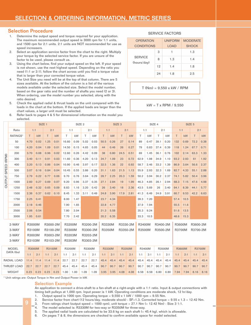
SELECTION & ORDERING INFORMATION, METRIC SERIES
9
1. Determine the output speed and torque required for your application. The maximum recommended output speed is 3000 rpm for 1:1 units, and 1500 rpm for 2:1 units. 2:1 units are NOT recommended for use as speed increasers.
2. Select an application service factor from the chart to the right. Multiply your torque by the selected service factor. If you are unsure of the factor to be used, please consult us.
3. Using the chart below, find your output speed on the left. If your speed is not shown, use the next highest speed. Depending on the ratio you need (1:1 or 2:1), follow the chart across until you find a torque value that is larger than your corrected torque value.
4. The Unit Size you need will be at the top of that column. There are 5 sizes available. At the bottom of the column is a list of the various models available under the selected size. Select the model number, based on the gear ratio and the number of shafts you need (2 or 3). When ordering, use the model number you selected, along with the ratio desired.
5. Check the applied radial & thrust loads on the unit compared with the loads in the chart at the bottom. If the applied loads are larger than the chart values, a larger unit must be selected.
6. Refer back to pages 4 & 5 for dimensional information on the model you selected.
Selection Procedure
OPERATION
CONDITIONS
UNIFORM
LOAD
MODERATE
SHOCK
SERVICE
(hours/day)
3 1 1.3
8 1.3 1.4
12 1.4 1.8
24 1.8 2.5
SERVICE FACTORS
T (Nm) = 9,550 x kW / RPM
kW = T x RPM / 9,550
SIZE 1 SIZE 2 SIZE 3 SIZE 4 SIZE 5
Ratio 1:1 2:1 1:1 2:1 1:1 2:1 1:1 2:1 1:1 2:1
RATINGS* T kW T kW T kW T kW T kW T kW T kW T kW T kW T kW
50 4.70 0.02 1.25 0.01 16.60 0.09 5.02 0.03 50.5 0.26 27 0.14 89 0.47 39.1 0.20 132 0.69 72.2 0.38
100 4.20 0.04 1.09 0.01 14.50 0.15 4.65 0.05 44 0.46 26 0.27 79 0.83 37.4 0.39 118 1.24 67.7 0.71
200 3.70 0.08 0.96 0.02 12.60 0.26 4.42 0.09 38 0.80 24.5 0.51 69 1.45 36.1 0.76 102 2.14 63.3 1.33
300 3.40 0.11 0.91 0.03 11.60 0.36 4.20 0.13 34.7 1.09 23 0.72 62.9 1.98 34.9 1.10 93.2 2.93 61 1.92
400 3.20 0.13 0.86 0.04 10.90 0.46 3.97 0.17 32.5 1.36 22 0.92 58.7 2.46 33.2 1.39 86.9 3.64 56.6 2.37
500 3.07 0.16 0.84 0.04 10.45 0.55 3.86 0.20 31.1 1.63 21.5 1.13 55.9 2.93 32.3 1.69 82.7 4.33 55.1 2.88
750 2.79 0.22 0.77 0.06 9.70 0.76 3.64 0.29 28.7 2.25 20.3 1.59 50.2 3.94 30.2 2.37 74.1 5.82 50.4 3.96
1000 2.60 0.27 0.69 0.07 9.20 0.96 3.37 0.35 27.1 2.84 19 1.99 46.3 4.85 28.1 2.94 68.3 7.15 47.6 4.98
1250 2.48 0.32 0.65 0.09 8.83 1.16 3.20 0.42 26 3.40 18 2.36 43.5 5.69 26 3.40 64.1 8.39 44.1 5.77
1500 2.36 0.37 0.62 0.10 8.45 1.33 3.11 0.49 24.8 3.90 17.9 2.81 41.3 6.49 24.9 3.91 60.7 9.53 42.2 6.63
1750 2.25 0.41 8.00 1.47 23.7 4.34 39.3 7.20 57.4 10.5
2000 2.18 0.46 7.90 1.65 22.8 4.77 37.9 7.94 55.5 11.6
2500 2.06 0.54 7.80 2.04 21.3 5.58 35.3 9.24 51.6 13.5
3000 1.95 0.61 7.70 2.42 20.2 6.35 33.3 10.5 48.6 15.3
OU
TPU
T S
PEE
D (
RP
M)
2-WAY
3-WAY
2-WAY
3-WAY
R3000M
R3100M
R3003M
R3103M
R3000-2M
R3100-2M
R3003-2M
R3103-2M
R3200M
R3300M
R3203M
R3303M
R3200-2M
R3300-2M
R3203-2M
R3303-2M
R3330M
R3350M
R3330-2M
R3350-2M
R3400M
R3500M
R3400-2M
R3500-2M
R3600M
R3700M
R3600-2M
R3700-2M
MODELDATA (lbs)
R3000M R3100M R3200M R3300M R3330M R3350M R3400M R3500M R3600M R3700M
1:1 2:1 1:1 2:1 1:1 2:1 1:1 2:1 1:1 2:1 1:1 2:1 1:1 2:1 1:1 2:1 1:1 2:1 1:1 2:1
RADIAL LOAD 11.4 11.4 11.4 11.4 22.7 22.7 22.7 22.7 45.4 45.4 45.4 45.4 45.4 45.4 45.4 45.4 45.4 45.4 45.4 45.4
THRUST LOAD 22.7 22.7 22.7 22.7 45.4 45.4 45.4 45.4 90.7 90.7 90.7 90.7 90.7 90.7 90.7 90.7 90.7 90.7 90.7 90.7
WEIGHT 0.23 0.23 0.23 0.23 1.00 1.00 1.09 1.09 3.95 3.95 4.08 4.08 6.58 6.58 6.80 6.80 7.94 7.94 8.16 8.16
* Unit ratings are: Output Torque in Nm and Output Power in kW.
Selection ExampleAn application to connect a drive-shaft to a fan-shaft at a right-angle with a 1:1 ratio. Input & output connections with timing belt pulleys at 1,000 rpm. Input power is 1 kW. Operating conditions are moderate shock, 12 hr/day.1. Output speed is 1000 rpm. Operating torque = 9,550 x 1 kW / 1000 rpm = 9.55 Nm.2. Service factor from chart (12 hours/day, moderate shock) - SF=1.3. Corrected torque = 9.55 x 1.3 = 12.42 Nm.3. From ratings chart (output speed = 1000 rpm), unit torque = 27.1 Nm (> 12.42 Nm) - Size 3 1:1.4. The model selected is: R3330M for two-way or R3350M for three-way.5. The applied radial loads are calculated to be 33.6 kg on each shaft (< 45.4 kg), which is allowable.6. On pages 7 & 8, the dimensions are checked to confirm available space for model selected.
800-713-6170 • www.andantex.com • [email protected]
10
SPECIAL UNITS
Service & Replacement PartsAll units can be serviced at our factory in Wanamassa, NJ. Field repairs are not covered under our warranty. Unit partslists are available upon request. Spare parts may be purchased from our factory, and are non-returnable.
WarrantyANDANTEX USA Inc., the manufacturer, warrants that for a period of 12 months from the date of installation or 18 months from the date of shipment, it will repair, or at its option, replace any new unit which proves defective in material or workmanship, or which does not conform to applicable drawings and specifications approved by the manufacturer. All repairs and replacements shall be F.O.B. factory. All claims must be made in writing to the manufacturer. In no event, and under no circumstances shall the manufacturer be liable for (a) damages in shipment; (b) failures or damages due to misuse,
abuse, improper installation or abnormal conditions of temperature, dirt, water or corrosives; (c) failures due to operation, intentional or otherwise, above rated capacities, and (d) non-authorized expenses for removal, inspection, transportation, repair or rework. Nor shall the manufacturer ever be liable for consequential and incidental damages, or in any amount greater than the purchase price of the unit.
This warranty is in LIEU OF ALL OTHER WARRANTIES, EXPRESS OR IMPLIED, INCLUDING (BUT NOT LIMITED TO) ANY IMPLIED WARRANTIES OF MERCHANT ABILITY OR FITNESS FOR A PARTICULAR PURPOSE. THE TERMS OF THIS WARRANTY CONSTITUTE ALL BUYER’S OR USER’S SOLE AND EXCLUSIVE REMEDY, AND ARE IN LIEU OF ANY RIGHT TO RECOVERFOR NEGLIGENCE, BREACH OF WARRANTY, STRICT TORT LIABILITY OR UPON ANY OTHER THEORY.
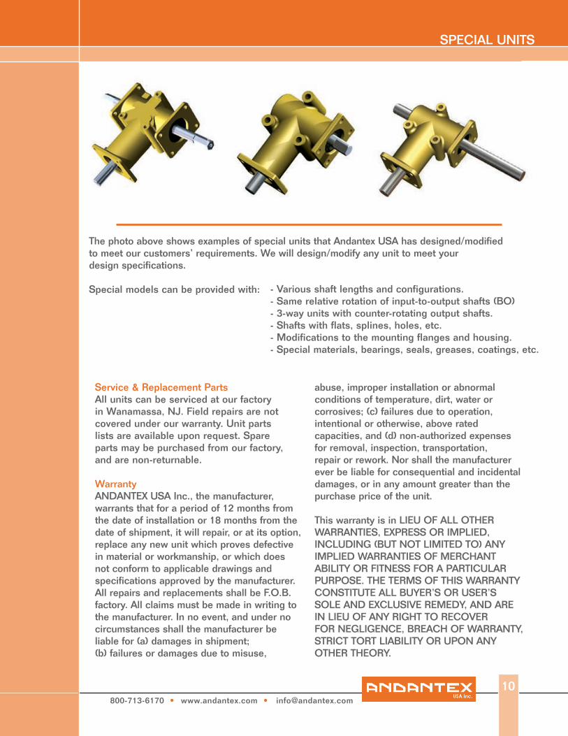
The photo above shows examples of special units that Andantex USA has designed/modified to meet our customers’ requirements. We will design/modify any unit to meet your design specifications.
Special models can be provided with: - Various shaft lengths and configurations.- Same relative rotation of input-to-output shafts (BO)- 3-way units with counter-rotating output shafts.- Shafts with flats, splines, holes, etc.- Modifications to the mounting flanges and housing.- Special materials, bearings, seals, greases, coatings, etc.

1705 Valley Road • Wanamassa, NJ 07712Phone: 800.713.6170 • 732.493.2812 • Fax: 732.493.2949 • E-mail: [email protected] • www.andantex.com