RIGblaster Advantageradiomanual.info/schemi/...RIGblaster_Advantage...The RIGblaster Advantage has...
75
www.westmountainradio.com 1020 Spring City Drive Waukesha, WI 53186 262-522-6503 [email protected] ©2015 West Mountain Radio, All rights reserved. All trademarks are the property of their respective owners. RIGblaster Advantage
Transcript of RIGblaster Advantageradiomanual.info/schemi/...RIGblaster_Advantage...The RIGblaster Advantage has...

www.westmountainradio.com1020 Spring City DriveWaukesha, WI 53186
©2015 West Mountain Radio, All rights reserved. All trademarks are the property of their respective owners.
RIGblasterAdvantage

Table of ContentsIntroduction About the RIGblaster Advantage . . . . . . . . . . . . . . . . . . . . 4 About the RIGblaster DVD . . . . . . . . . . . . . . . . . . . . . . . . 5 Digital-Mode Operating . . . . . . . . . . . . . . . . . . . . . . . . . . . 5
Package Contents . . . . . . . . . . . . . . . . . . . . . . . . . . . . . . . . . 6
Controls, Connections and Features . . . . . . . . . . . . . . . . . . 7
Choosing the Correct ISC . . . . . . . . . . . . . . . . . . . . . . . . . . . 8
Software Driver Installation Windows, Linux & Mac Drivers . . . . . . . . . . . . . . . . . . . . . 10 How to Renumber the RIGblaster Advantage COM port . . 14
Transceiver Connections . . . . . . . . . . . . . . . . . . . . . . . . . . . 15 Required Connections . . . . . . . . . . . . . . . . . . . . . . . . . . . . 15 Optional Connections . . . . . . . . . . . . . . . . . . . . . . . . . . . . 15
RIGblaster Settings Audio Levels . . . . . . . . . . . . . . . . . . . . . . . . . . . . . . . . . . . 16 PTT (Keying your radio) . . . . . . . . . . . . . . . . . . . . . . . . . . 18 Morse (CW) Operation . . . . . . . . . . . . . . . . . . . . . . . . . . . 19 RTTY (FSK) Operation . . . . . . . . . . . . . . . . . . . . . . . . . . . 19 CAT . . . . . . . . . . . . . . . . . . . . . . . . . . . . . . . . . . . . . . . . . . 20Transceiver Settings Operation Mode . . . . . . . . . . . . . . . . . . . . . . . . . . . . . . . . . 21 Recieve Settings . . . . . . . . . . . . . . . . . . . . . . . . . . . . . . . . 22 Transmit Settings . . . . . . . . . . . . . . . . . . . . . . . . . . . . . . . . 22
Software Configuration FLDigi (Multiple Digital Modes) . . . . . . . . . . . . . . . . . . . . . 23 Airlink Express (PSK31, RTTY & MFSK-16) . . . . . . . . . . . 26 MMTTY (RTTY FSK) . . . . . . . . . . . . . . . . . . . . . . . . . . . . . 30 MRP40 (Morse Code) . . . . . . . . . . . . . . . . . . . . . . . . . . . . 33 JT65-HF: (JT Modes) . . . . . . . . . . . . . . . . . . . . . . . . . . . . 35 Winlink 2000 with RMS Express (WinMOR) . . . . . . . . . . . 38 UZ7HO Sound Modem (Packet Radio) . . . . . . . . . . . . . . . 41 MMSSTV (Analog SSTV) . . . . . . . . . . . . . . . . . . . . . . . . . 45 Easy Pal (Digital SSTV) . . . . . . . . . . . . . . . . . . . . . . . . . . 48 FreeDV (Digital HF Voice) . . . . . . . . . . . . . . . . . . . . . . . . . 51 Ham Radio Deluxe & DM-780 . . . . . . . . . . . . . . . . . . . . . . 55
3West Mountain Radio Operating Manual
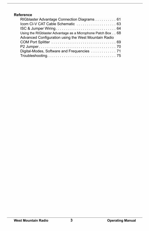
Reference RIGblaster Advantage Connection Diagrams . . . . . . . . . . 61 Icom CI-V CAT Cable Schematic . . . . . . . . . . . . . . . . . . . 63 ISC & Jumper Wiring . . . . . . . . . . . . . . . . . . . . . . . . . . . . . 64 Using the RIGblaster Advantage as a Microphone Patch Box . . 68 AdvancedConfigurationusingtheWestMountainRadio COM Port Splitter . . . . . . . . . . . . . . . . . . . . . . . . . . . . . . . 69 P2 Jumper . . . . . . . . . . . . . . . . . . . . . . . . . . . . . . . . . . . . . 70 Digital-Modes, Software and Frequencies . . . . . . . . . . . . 71 Troubleshooting . . . . . . . . . . . . . . . . . . . . . . . . . . . . . . . . . 75

4West Mountain Radio Operating Manual
Introduction
About The RIGblaster Advantage We understand you have a choice when buying Amateur Radio products and we would like to take a moment to thank you for choosing West Mountain Radio. The RIGblaster Advantage has been designed with you, the digital-mode operator in mind. It has many outstanding features which will at the same time enhance and simplify your operating. Some of the features of the RIGblaster Advantage which put it ahead of the competition include;
•COM port push-to-talk (PTT) keying. •A high-quality built-in USB sound card with level controls (both RX
& TX) on the front panel.•Pre-wired Instant Setup Connectors – no more complex jumper
wiring!•Rig-control (CAT/CI-V).* • FSK jack for operating FSK RTTY.**•CW keying jack for operating Morse Code.•Digital VOX with adjustable delay.•Separate audio jacks for received and transmitted audio.• Foot-switch PTT input.•USB virtual serial port with RS-232C externalization• TX inhibit switch.
Connection to your computer is made very simple with the supplied USB cable. We will go into connecting up your RIGblaster Advantage in the firstchaptersodonothookituprightaway.
Pleasereadthroughthismanualfirst(especiallythedriverinstallationsection)andyouwillfindtheRIGblasterAdvantagewillprovideyouwithmany years of reliable service and enjoyment.
* Rig control is only available on certain transceivers.** FSK requires the transceiver to have a dedicated RTTY mode, an optional FSK cable and the software must support serial FSK.

5West Mountain Radio Operating Manual
About the RIGblaster DVD The supplied DVD is mostly a collection of various digital-mode software programs for use with sound card interfaces like the RIGblaster Advantage.
The programs contained on the disc were not written by West Mountain Radio. Some are completely free while others are commercial. We have however tested our products on the majority of them.
Amateur radio software is constantly evolving and we encourage you to visit the various authors websites to check for updates for software you wish to use.
We maintain a list of website addresses for the software we place onto the DVD (as best we can) and you can access this page from:
http://www.westmountainradio.com/content.php?page=links
Introduction To Digital-Mode OperatingMost modern digital-modes can be operated on the RIGblaster Advantage. Some of these may already be familiar to you. For instance PSK31, JT65 & RTTY are very commonly heard on the bands.If you have the ability try tuning to 14.070MHz (usb) and chances are you will hear multiple PSK31 QSOs taking place.
Moving up to 14.073MHz you may hear the tones of the MFSK modes suchasOlivia,Contestia,ThorandMFSK-16.Youwillalsofindthe“cricket-like” chirping of Feld Hell.
Tune to 14.076MHz and you will hear JT65 signals. Going up another 10KHz lands you right in a very popular RTTY segment.Moving up through 14.100MHz you should hear packet networks, WinMOR and the wider band digital modes signals such as MT63, ALE and Pactor.
14.230MHz (usb) yields a very active SSTV (Slow Scan TV) frequency. This is traditional analog SSTV. Another 3KHz up (14.233MHz) is the main watering-hole of digital SSTV enthusiasts.14.236MHz is currently very popular with the digital voice experimenters using FreeDV software.It is worth noting there are some modes in use which cannot be used with the RIGblaster Advantage (nor any sound-card based interface).
These are the arq modes Pactor, G-TOR, Amtor and Clover.These modes require very precise timing cycles which Windows is unable to deliver. Amtor, G-TOR and Clover are very seldom used these days but Pactor is commonly employed for mail messaging using the Winlink 2000 system.

6West Mountain Radio Operating Manual
In practice this is not much of a limitation as the RMS Express software (using WinMOR) makes mail/e-mail messaging simple using the RIGblaster Advantage.
Many digital-modes (such as PSK31) will work far down into the noise level. It is not uncommon to see copy on your screen even when you havedifficultyhearingthesignalonyourspeaker.
This also implies you do not need to run high power levels during normal conditionsandformostdigital-modesyouwillfind20-40Wample.Infact, running close to maximum output on your radio is self-defeating. In this case you stand a very good chance of having a spread-out badly distorted signal (think QRM!) and you may even damage your rig on long overs as many transceivers are not designed to run high duty-cycle transmissions for extended periods.
Atthebackofthismanualyouwillfindasimplechartofdigital-modes,software and frequencies to try. These are just suggestions but will help you get started navigating the world of HF digital-modes.
Package ContentsThe following is a list of the contents for the RIGblaster Advantage. Verify that all the following items were included:
*The RIGblaster Advantage cover is loose so you may easily remove it to install jumpers.
QTY ITEM1 RIGblaster Advantage1 Owner’s Manual7 Instant Setup Connectors8 Single Pin White Jumpers5 Mini Blue Shunt Jumpers4 #6 Black Metal Screws (*for cover)4 Adhesive Pads and Rubber Feet1 Microphone Cable (RJ-45 to 8 Pin Screw-On1 1/8” Stereo Mini Plug Cable1 USB (A/B) Cable1 DVD

7West Mountain Radio Operating Manual
Controls, Connections And Features
Mic
roph
one
outp
ut fo
r 8 p
in
roun
d m
ic:u
sed
with
cab
le
(Mic
inpu
t with
RJ4
5 co
nnec
-to
r rad
io
PTT
in/o
ut R
CA
Con
nect
or (u
sed
with
foot
-sw
itch
or o
ther
PTT
sw
itch
or c
onne
ctio
n.
Aud
io li
ne in
put (
outg
oing
aud
io
from
you
r rad
io c
onne
cts
here
Rad
io tr
ansm
itted
aud
io (a
llow
s yo
u to
mon
itor a
udio
rece
ived
by
radi
o)C
ompu
ter t
rans
mitt
ed a
udio
allo
ws
you
to m
onito
r tra
nsit
audi
o fro
m P
CC
W/F
SK
key
ing
outp
ut (c
on-
nect
s to
radi
o ke
ying
inpu
t
CAT
RIG
Con
trol a
t RS
232
Leve
ls
CAT
/CI-V
rig
cont
rol (
Con
nect
s to
ra
dio
with
acc
esso
ry c
able
)
US
B to
inte
rface
(Rea
d dr
iver
in
stal
l bef
ore
conn
ectin
g.
PTT
SoftwareConfigC
OM
: RTS
Con
trol
PTT
DTG
R C
ontro
ls C
W/F
SK
off:
com
-pu
ter c
an n
ever
act
ivat
e P
TT o
r CW
/FS
K V
OX:
PTT
and
CW
/FS
K a
ctiv
ated
au
tom
atic
ally
by
audi
o.
US
B L
ED
(lig
hts
whe
n un
it is
pow
-er
ed. W
ill b
link
whe
n so
ftwar
e is
re
ceiv
ing
or tr
ansm
ittin
g au
dio
PTT
LE
D (l
ight
s w
hen
softw
are
activ
ates
tran
smits
)
Mic
roph
one
inpu
t for
8 p
in ro
und
mic
(M
ic o
utpu
t with
RJ4
5 co
nnec
tor r
adio
)
Tran
smit
audi
o le
vel (
Use
in
conj
unct
ion
with
com
pute
r vo
lum
e le
vel
Rec
eive
aud
io le
vel (
Use
in c
onju
nctio
n w
ith c
ompu
ter a
udio
leve
l
If V
OX
ena
bled
, con
trols
leng
th o
f tim
e tra
nsm
it is
act
ive
FSK
/CW
LE
D (l
ight
s w
hen
softw
are
acce
sses
ser
ial
DTR
line
for F
SK
/CW
key
ing.
Als
o lig
hts
in V
OX
m
ode
and
indi
cate
s si
gnal
leve
l)

8West Mountain Radio Operating Manual
Choosing the Correct ISCConfiguringtheRIGblasterAdvantagewithatransceiverisverysimpleby use of the Instant Setup Connectors (ISC). These take the place of jumper wiring for many common radios.
EachISCisrespectivelyidentified:IcomRoundMetal,IcomRJ45Modular, Yaesu Round Metal, Yaesu Round Metel – Isolated, Yaesu RJ45 Modular, Kenwood Round Metal and Kenwood RJ45 Modular.Depending on the transceiver in use, one of these ISCs will need to be installed inside the RIGblaster Advantage before use. They take care of all the microphone connection wiring that previously was done by installing jumper wires and shunts. If using a non-standard microphone wiring, jumper wires and and blue shunts have been provided in the package contents. The ISCs cover most popular brands and models of radios.
Observe the microphone connector on the radio. Typically it will be one of two types – either an 8-pin round metal connector or an RJ- 45 “square” modular jack. The RIGblaster Advantage is designed to interface the transceiver through the microphone jack. Be sure to select the ISC that matches the connector on the radio.
Chart of ISCs For Some Common Radios:
Manufacturer Model ISCIcom All 8 pin round mic jack radios (e.g., IC-746, IC-756/
Pro/III,IC-7600)Icom 8 Pin Round
Icom All RJ-45 modular mic jack radios (e.g., IC-706, IC-7000)
Icom RJ-45 Modular
Yaesu All older 8 pin round mic jack radios (e.g., FT-840, FT-757, FT-920)
Yaesu 8 Pin Round
Yaesu All newer 8 pin round mic jack radios (e.g., FT-950, FT-2000, FTDX-3000, FTDX-5000, FTDX-9000)
Yaesu 8 Pin Round- Isolated
Yaesu All RJ-45 modular mic jack radios (e.g., FT-817, FT-857, FT-897, FT-450)
Yaesu RJ-45 Mdular
Kenwood All 8 pin round mic jack radios (e.g. TS-570, TS-2000, TS-590S, TS-990S)
Kenwood 8 Pin Round
Kenwood Most RJ-45 modular mic jack radios (e.g. TM-V71) Kenwood RJ-45 ModularElecraft K3 & K2 use the same mic jack as Kenwood Kenwood 8 Pin RoundTen Tec Omni VII & Orion II use the same mic jack as newer
Yaesu radiosYaesu 8 Pin Round – Isolated
Flex Flex 1500 and 3000 use the same mic jack as Yaesu RJ-45 radios
Yaesu RJ-45 Modular
Flex Flex 5000 and 6000 series use the same mic jack as newer Yaesu radios
Yaesu 8 Pin Round - Isolated

9West Mountain Radio Operating Manual
Locate the correct ISC for the radio and install it on the ISC header (2 rows of 13 pins) located inside the RIGblaster Advantage ensuring pin 1 on the ISC matches pin 1 on the header.
Example: Installation of a Kenwood RJ45 Modular ISC inside the RIGblaster Advantage. Notice the orientation of the ISC and the location of pin 1.
Some radios use a 4-pin round microphone connector, these include older Kenwood and Yaesu transceivers and some Ten-Tec radios. An adapter will be needed to use the RIGblaster Advantage with these radios. The correct adapter is SKU 58136-1000 and available online for purchase.
Radios with 6 pin microphone connectors such as the Yaesu FT-100D will require our optional “Yaesu Modular 6” cable (SKU 58118-982). This cable comes with a jumper diagram and a resistor for correct operation.

10West Mountain Radio Operating Manual
Software Driver InstallationThe RIGblaster Advantage when properly installed in Windows, Linux or Macintosh operating systems will provide two new hardware devices; a serial port and a sound-device.
Afterthedriversinstallationhasfinished,thegreenledmarked“USB”on the front of the RIGblaster Advantage will be illuminated. During installation,thered“XMIT”ledmayflickerafewtimes.Thisisnormaland does not indicate a problem.
The green “USB” led will blink when the Advantage sound card is in use and remain solid when idle. Blinking does not indicate any fault!
Linux InstallationWest Mountain Radio drivers have been included in the Linux kernel since version 3.8.4. Most recent distributions should have no problem automatically recognizing the RIGblaster Advantage.
In most Debian/Ubuntu distributions before you can access a serial device you will have to add your username to the dialout group.
To do this, bring up a terminal window and enter the following command:
sudo usermod -a -G dialout <username>
Where <username> is your login name.
After you do this you will need to logout and log back in for the changes to take effect. The sound device driver needs no special such permissions.
Note: You can verify if the serial device is present by opening a terminal and using the command:
ls -l /dev/ttyU* which will list all USB serial tty devices.
If you have more than one USB serial device on your system you can use the following command to determine which ttyUSB device number is assigned to the RIGblaster:
ls -l /dev/serial/by-id | grep ‘RIGblaster’

11West Mountain Radio Operating Manual
For older distributions and troubleshooting visit the following support page: http://www.westmountainradio.com/adv/drv/linux
Macintosh Installation The RIGblaster Advantage will work with OS X 10.5 and above. Drivers and instructions are available online:
http://www.westmountainradio.com/adv/drv/macosx
Windows InstallationYou have two choices of automatic installation on Windows systems.
Quick Method (For advanced Windows users running Vista, Windows 7 or Windows 8)As long as your computer is online, you can simply plug in the USB cable to your computer and the RIGblaster Advantage. This will trigger the “Found New Hardware Wizard” and you will be asked if you want to do an automatic install. Answer yes and allow Windows to connect to Micro-softUpdatetoretrievethesigneddrivers.Youwillbenotifiedwhentheprocess is complete. This can take a few minutes so be patient.This method may not work on Windows XP or earlier versions of Win-dows. In this case you are advised to use the standard method of instal-lation detailed below.
Standard Method (Recommended for most users)Do not attach the RIGblaster Advantage.
Insert the DVD into your computer which should autoplay. You will be promptedthefirsttimeyouinsertthisdiskifyouwanttoinstalltheRIG-blaster Survey/Diagnostic Program. Answer yes to all steps and this will pre-load all West Mountain Radio drivers for you. After it has installed you may attach the RIGblaster Advantage.
Manual InstallationForthosestillusingWindows2000orWindows98youwillfindadriverpackage available from http://www.westmountainradio.com/adv/drv/win2k
In the case of Windows 98 it must be Windows 98SE and have all the Microsoft issued USB updates applied before it will work.
After successful installation a good idea is to check Windows Device Manager and verify there is a new COM port and audio device.

12West Mountain Radio Operating Manual
Finding Device Manager in Windows XP:1. Open the Windows Control Panel (Start->Settings->Control Panel)2. Look for the System icon and double-click it.3. Choose the “Hardware” tab at the top and click the button marked “Device Manager”.
Finding Device Manager in Windows 7:1. Open the Windows Control Panel (Start->Settings->Control Panel)2. Change Control Panel to “View By Small Icons”3. Click on the icon labeled “System”4. Click on the icon labeled “Device Manager” 3. Choose the “Hardware” tab at the top and click the button marked “Device Manager”.
Finding Device Manager in Windows 8:1. From the Start screen, swipe up to bring up the Apps screen. With a stylus or mouse, click the circled down-arrow icon instead. Note: If you’re not running the Windows 8.1 update or later, swipe up from the bottom of the Start screen and tap the All apps icon. With a mouse, right-click on the Start screen and then click All apps.
2. Once on the Apps screen, scroll or swipe to the right until you see the Windows System heading.
3. Tap or click on Control Panel, located under Windows System.
4. Windows 8 will bring up the Desktop and automatically open the Con-trol Panel.
5. Tap or click on the Hardware and Sound link. Note: You won’t see Hardware and Sound if your Control Panel view is set to Large icons or Small icons. In your case, just tap or click on Device Manager and then move on to Step 6.
6. In the Hardware and Sound window, click or tap Device Manager, located under the Devices and Printers heading.

13West Mountain Radio Operating Manual
A window similar to the one shown here should appear. There will be a section called “Ports (COM & LPT)” which can be expanded to view by clicking on the + symbol to the left.
Look for the entry West Mountain Radio RIGblaster Advantage. Imme-diately after this text, look for the COM port number in parenthesis (e.g. COM5).Makeanoteofthisasitwillbeneededtoconfiguredigitalmodesoftware to use this COM port later.
When expanding the section marked “Sound, video and game control-lers”, notice the new entry labeled RIGblaster Advantage Audio (Shown as USB Audio Device in Win XP or earlier).

14West Mountain Radio Operating Manual
Windows may assign any number for the COM port. Windows typically treats COM1 to COM4 as special and does not normally use them for USB serial devices. Therefore, it is not recommended to renumber the RIGblaster Advantage COM port to a value lower than 5 unless you have to.
How To Renumber The RIGblaster Advantage COM portIfyoufinditnecessarytorenumbertheRIGblasterAdvantageCOMport,e.g., for use with older software which requires a lower COM port number we have created an application to allow you to do this easily. It is part of the West Mountain Radio Diagnostic program “WMRDiagnostics” which is available on the supplied DVD. You may already have it installed if you followed the standard installation.
Click the WMR icon on your system tray – it looks like this:
A window will appear listing your computer serial ports and West Moun-tain Radio RIGblasters.
Right-click over the RIGblaster Advantage entry and choose “Change Port #”. A new window will appear allowing you to enter a new COM port number. Make sure you choose one that isn’t already in use!

15West Mountain Radio Operating Manual
Transceiver ConnectionsNow hook up the RIGblaster Advantage to the radio. Follow the steps in the next section and refer to the connection diagrams if necessary (located in the back of this manual).
Required Connections1. Disconnect the microphone from the transceiver.
2. Reconnect the microphone to the RIGblaster Advantage. Note: There will be only one connector on the Advantage that will mate with the microphone plug; either the 8-pin round metal socket mating to the front panel or the square RJ-45 connector mating to the rear panel.
3. Connect the 8-pin (round) to RJ-45 (square) microphone cable, included in the package contents, to the transceiver’s microphone input socket. There will be only one end that will mate with the transceiver’s microphone socket.
4. Connect the other end of the microphone cable to the RIGblaster Advantage.
5. Take the 1/8” inch stereo patch cable and connect one end to the transceiver’s speaker out (or headphone) jack. Note: If the transceiver uses a 1/4” jack, it will require use of 1/8” inch to 1/4” stereo adapter.
6. The other end of the patch cable should be connected to the jack labeled LINE IN on the rear of the RIGblaster Advantage.
If you have our optional FSK cable then you would not perform steps 5 and6above.Connecttheflyingleadmarked“Audio”totheLINEINjack.
Optional ConnectionsAdditional jacks are provided on the rear of the RIGblaster Advantage for operation enhancement:
1. Serial DB-9. This connector can be used to interface some transceivers that require RS-232C level CAT. Note: This serial connector is a hardware extension of the USB virtual serial port. All lines are connected but take note that some control lines are used by the RIGblaster Advantage for PTT & CW/FSK.
2. CTL IN/OUT. This is a TTL level jack providing CI-V/CAT rig control. Many radios can be interfaced to this jack with a low-cost cable for complete rig control with suitable software.

16West Mountain Radio Operating Manual
3. CW/FSK. This jack can be used for serial port CW keying or FSK shift if your transceiver supports it.
4. AUDIO OUT. This jack provides a transmitted audio output. Connect amplifiedcomputerspeakersorapairofminiearphonesherefortransmit monitoring.
5. SPKR OUT. This jack provides a rig receive audio output. Connect an external speaker here only if not using our optional FSK cable.
6. PTT IN/OUT. This RCA phono jack is primarily used for connection to a foot-switch for PTT. The contacts are in parallel with the Advantage PTT relay (rated 30 VDC 2A max.) and in parallel with the transceiver’s microphonePTTline,andwillfloatatthesamevoltage.
RIGblaster Settings
Audio LevelsProper audio level setting is crucial to successful digital-mode operation.The RIGblaster Advantage transmit audio level can be set by use of the Windows playback volume slider and the convenient front panel XMIT LEVEL control.
Receive level can be set by the Windows recording volume slider and the front-panel RCV LEVEL control.
It is recommended to set the RIGblaster Advantage audio device levels to 50% for both “recording” and “playback” within Windows. Fine tuning can then be made using the XMIT & RCV level controls on the front of the Advantage.
It is important not to set the RIGblaster Advantage as the default Windows audio device. This will prevent any unintentional transmissions if operating in VOX mode (Windows audio-alerts, music etc).
Note: Some older digital-mode software only uses the default sound card in Windows for output. If using such software be careful when assigning the default Windows sound-card to the Advantage. In this case, it is recommended to change the Windows sound scheme to silent.
To access your Windows audio levels use the “Sound” icon in Control Panel and refer to the images shown below.

17West Mountain Radio Operating Manual
You can also use the “Sound” program to assign which sound card is the default device by right-clicking a device (in this case the internal computer sound card) and choosing “Set as default device”.
Note: The RIGblaster sound card should not be set as the “default communication device” for either record or playback.
Ifyoufindthattransmitaudioistoo“hot”thentryreducingtheplaybackvolume to about 10%. If that doesn’t help there is a single jumper in the Advantage which will further attenuate transmit volume by 20dB. It is located next to one of the audio transformers and should be shorted for the attenuator to be active.
Setting The Playback (TX) Volume

18West Mountain Radio Operating Manual
Setting The Record (RX) Volume
PTT (Keying Your Radio)On the front-panel of the RIGblaster Advantage there is a three position switch labeled TX. This controls how PTT is activated (the method by which the transceiver goes into transmit).
Position 1 – COM The Advantage is under computer control and switches the transceiver between transmit and receive depending on the state of the serial port RTS control signal.
Position 2 – OFF The Advantage is prevented from activating transmit on the transceiver. Note: The RCA foot-switch input is still active.
Position 3 – VOX The Advantage contains circuitry which detects the presence of an audio transmit signal and automatically switches the transceiver into transmit. When the signal ends the transceiver is returned to receive mode.
The VOX method of operation is suitable for many digital-modes and oftensimplifiessoftwareconfiguration.Anexampleofthiswouldberunning a logging program (which requires exclusive use of the serial port to read frequency and mode) but having the ability to run a preferred PSK31 program simultaneously. Using VOX mode allows the PSK31 softwaretokeytherigwithoutconflictingwiththeloggingprogram.(Note: There is no need to use the transceiver VOX setting).

19West Mountain Radio Operating Manual
Morse (CW) OperationThe RIGblaster Advantage has two methods of sending Morse Code (CW).
One method is using MCW (Modulated or Tone CW) in SSB or FM modes. Some computer software will only produce this type of CW.
The second, and preferred, method is to use serial port keying:
Connect a stereo patch cable from the RIGblaster Advantage’s CW/ FSK jack to the transceiver’s CW keying jack. This will permit Morse operation when using the radio’s CW mode with suitable software.
This hardware CW keying is realized by use of the DTR control line on the COM port. Refer to the example of setting up CW keying using the MRP40 software shown later in this manual. It is also possible to operate MCW in VOX mode, in which case the DTR circuit is logically OR’ed with PTT - the result is hardware keying from software which only has the MCW method available. Note: This is an excellent way of producing hard CW keying from the fldigi software.
By using a dual 1/8th inch stereo adaptor plug (or ‘Y’ splitter cable), connect the Morse Key in parallel with the CW jack. The output is open collector so is safe to use with contact-closure Morse Keys and modern “pull to ground” electronic keyers. This will allow to send computer Morse orusethekeyformaximumflexibility.Warning:Donotattemptthisifyour radio uses grid-block keying or cathode keying - you will destroy your Advantage!
RTTY (FSK) OperationSimilar to CW, there are two methods used to generate RTTY signals.Method one is AFSK RTTY being used in SSB mode. This relies on the software to generate the RTTY tones. Most digital-mode software will use this method.
The other method, FSK RTTY, may also be used by some PC software. Only transceivers that have an RTTY mode and FSK shift input will work in this method. A special cable is required to interface from the CW/FSK jack on the RIGblaster Advantage to the FSK input on the transceiver. FSK shift input is controlled by the serial DTR line. Note: PTT is also required and provided by serial RTS.
Refer to the MMTTY example later in this manual for an example of configuringFSK.

20West Mountain Radio Operating Manual
FSK Cables Available From West Mountain Radio:
CAT OperationThe RIGblaster Advantage is equipped with TTL and RS-232C level CAT. This makes it possible to use software for logging or radio control in addition to digital modes all through the same interface.
Most modern radios have a CAT jack and with very few exceptions the RIGblaster Advantage can be connected to this via an optional cable for full computer control.
The CAT jack on your radio is a serial interface (using TxD/RxD) which can receive instructions and send information back to your computer to be used with suitable software.
The serial interface on the Advantage is implemented through same COM port we use for PTT and CW/FSK keying. It is externalized on the RIG CTL jack (TTL) or the DB-9 (RS-232C). Note: Both jacks cannot be in use at the same time.
Hardwareflow-controlshouldnotbeusedunlesstheRIGblasteris operating in VOX as the radio will hold RTS high and cause the transmitter to be permanently in transmit mode.
Ifyourradiocannotdisableflow-control(e.g.,KenwoodwithRS-232C) then we recommend you use our Kenwood CAT cable (SKU 58119-1432) which will allow proper operation of the RIGblaster in COM mode or use a separate USB to RS-232C adapter cable for CAT.
SKU Used On58129-995 Icom radios with a 13 pin accessory jack
(e.g., IC-706, IC-718, IC-7000)58129-994 Icom radios with an 8 pin accessory jack
(e.g., IC-746, IC-756/Pro/II)58131-999 Kenwood radios with a 13 pin accessory jack
(e.g., TS-2000)58131-998 Yaesu radios with a 4 pin ‘RTTY’ jack
(e.g., FT-1000, FT-2000,FTDX-5000)

21West Mountain Radio Operating Manual
CAT Cables Available From West Mountain Radio:
In summary, the serial control lines used by the RIGblaster Advantage are shown in the table below:
Transceiver Settings Operating ModeMost digital mode programs expect the transceiver to be used in usb (upper sideband).
Traditionally, digital mode transmission was done in lsb (lower sideband) most modern software makes the assumption this is no longer the case. For some modes such as PSK31 (which is sideband independent) it actually makes no difference but to be “on the same page” with other operators you should choose usb unless you have good reason not to.The two exceptions to this would be real-keyed Morse Code (use CW mode) and FSK generated RTTY (use RTTY mode).
Because the RIGblaster Advantage connects to a transceiver microphone jack it is important not to choose a “data” or “dig” mode on the radio. These modes typically expect transmit modulation through an accessory jack and will disable the microphone jack.
SKU Used On58107-971 All CI-V equipped Icom radios (i.e., Icom radios
with a “remote” jack)58108-972 Yaesu radios with an 8 pin mini din CAT jack
(e.g., FT-817, FT-857,FT-897)58108-974 Yaesu radios with a 6 pin din CAT jack (e.g.,
FT-736, FT-747, FT-767, FT-990)58119-1432 Kenwood radios with an RS-232C CAT jack
(e.g. TS-480, TS-570, TS-2000)
Serial Line FunctionRTS Transceiver PTTDTR CW Keying (with CW software). Radio in
CW mode.DTR FSK Keying (with RTTY software). Radio in
RTTY mode.TxD/RxD CAT

22West Mountain Radio Operating Manual
Receive Settings For most digital modes setting your AGC (automatic gain control) to “auto”or“fast”isrecommended.Youmayfindsomemodes(e.g.,FeldHell&CW)willbenefitfromslowAGCaction.Thereisnohardandfastrule for this so experimentation is advised.
Receivefilteringisnormallyleft“wideopen”butifyouhavetheabilitytoalter your receive bandwidth in usb mode you may do so which may help with co-channel interference in crowded conditions. When operating FSK RTTYyoucanuseanynarrowfilteringyouradiohasavailable.
If your radio has DSP noise reduction it should be turned off. The only modeswhichmaybenefitfromsomenoisereductionareFeldHell&CW.UsingDSPnoisereduction(orDSPauto-notchfiltering)willadverselyaffect reception of many digital signals.
The transceiver’s Noise Blanker ideally should be turned off but that may not be possible if you live in a high noise area.
Transmit SettingsThe most important thing to avoid when transmitting digital modes is a distorted signal. This can happen when the drive to the microphone jack is too high or when your transceiver’s ALC (automatic level control) is active. It is recommended to leave your RF Power control set to maximum (usually 100W) and adjust the drive level using the RIGblaster’s XMIT LEVEL control and/or the Windows playback slider to achieveyourfinaloutputpower.Note:It’simportanttorealizethatsettingyour RF Power control to 100W does not imply you are transmitting a 100W signal! It simply leaves enough “headroom” to prevent ALC action from occurring.
Determining your output power can be problematic with digital mode operating as some modes have a high P(peak) to P(mean) ratio. Unless your power meter shows PEP with hold you may not get a very accurate indication of output power in these modes.
Fortunately PSK31 has a P(peak) to P(mean) ratio of approximately 0.79 so what you see on the meter is close to your actual output power.On the other hand, MT63 has a ratio of about 0.1 which would mean that transmitting a properly adjusted MT63 signal may indicate only 10W on an average power meter for a peak output of 100W. Trying to increase the drive will only distort the signal!
There is never a good reason to use your speech processor function while transmitting a digital mode – so turn it off!

23West Mountain Radio Operating Manual
As you will be transmitting in usb mode, the transceiver’s mic gain control will have a bearing on your output power. We recommend you leave your mic gain set to your normal level for operating phone and only adjust drive with the XMIT LEVEL and/or Windows playback slider control.
PSK31 rule-of-thumb: Ensure no ALC indication is shown on your meter while transmitting and aim for no more than 40W output. You should be transmitting a clean signal and being a “good HF neighbor”.
Software Configuration This section of the manual provides an overview of some of the most popular and current ham radio software that has been tested with the RIGblaster Advantage. This is not an exhaustive reference on the softwarebutmoreofaquickguidetogettingbasicsconfigured.Keeping in mind that these are Third-Party software programs, West Mountain Radio cannot guarantee it will work with every particular PC & radio.
Most of this software is under constant development so some features referred to in this manual may not be exactly as described in future versions released by the respective authors.Alsoincludedarescreencapturestoaidinconfiguringthesoftwarewiththe RIGblaster Advantage.
Fldigi Suite Modes supported: CW, Contestia, DominoEX, Hell, MFSK, MT63, Olivia, PSK, QPSK, PSKR, RTTY, THOR, Throb, WEFAX, Navtext & NBEMS modes.
W1HKJ’s Fldigi is a very capable, cost-free, and easy to use digital mode program. It has all of the most popular modes in use today (including PSK31) and its decode performance is highly regarded.

24West Mountain Radio Operating Manual
Many of its EMCOMM modes (NBEMS) are used on HF & VHF under control of other software which provides error-checking and automatic repeat request (ARQ). It also supports logging and integrated CAT by a variety of methods. It is under constant development and is multi-platform. There are builds for Windows, Macintosh and Linux available from the author’s website.
Note: The CW mode in Fldigi is tone modulated Morse Code (MCW). Normally operated in SSB mode on HF and FM mode on VHF/UHF, the RIGblaster Advantage can convert this into real-keyed CW when the switch is in the VOX mode and a stereo patch cable hooked to the CW jack on both the Advantage and radio.
Configure Fldigi To Use The RIGblaster Advantage Sound-device.
1.Choose“Configure”fromthemainmenu.2. Choose “Sound Card” from the popup menu.3.Choose“Audio”fromthefirstrowoftabs.4. Choose “Devices” from the second row of tabs.5. Select the “Port Audio” checkbox.6. Assign “RIGblaster Advantage Audio” to both of the “Capture” and “Playback” drop-down boxes.7. Click on “Save” to make the changes permanent.

25West Mountain Radio Operating Manual
Setting Up Fldigi For Hardware PTT.
1.Choose“Configure”fromthemainmenu.2. Choose “Rig control” from the popup menu.3.Choose“Rig”fromthefirstrowoftabs.4. Choose “Hardware PTT” from the second row of tabs.5. Select the “Use separate serial port PTT” checkbox.6. Assign the Advantage COM port in the “Device” drop-down.7. Select the “Use RTS” checkbox.8. Ensure “Use DTR” is not selected.9. Ensure “RTS=+V” is not selected.10. Ensure “DTR=+V” is not selected.11. Click on “Initialize”.12. Click on “Save” to make the changes permanent.

26West Mountain Radio Operating Manual
Setting Up Fldigi For Rig-controlFLdigi offers a number of methods of rig-control; beyond the scope of this manual to detail them all. Hamlib (on the rig-control tab) may be the simplestmethod,asFLdigicomeswithrigdescriptionfilesforthislibrary.
RigCATisanothergoodmethod.Downloadarigdescriptionfileforaspecificradiobygoingto:http://www.w1hkj.com/xmlarchives.html.
TypicalConfiguration:
1. Specify the Advantage COM port as the rig-control “device”. Note: Do not set RTS or DTR high, otherwise, the transceiver will go into transmit whentheprogramfirstloads!
2. Match the transceiver’s communication settings – check CAT baud rate and optionally CI-V address if using an Icom radio.
3. Flow control is not usually needed, but if required, use XON/XOFF as the method. Never choose hardware CTS/RTS.
Flrig is a stand-alone CAT program which will interface to Fldigi through the XML-RPC method. This is a preferred method of CAT for many operators using Fldigi. It is available on the author’s homepage.
Airlink ExpressModes Supported: PSK31, QPSK31, MFSK and RTTY
Airlink Express is designed to be a modern, user-friendly program which previous operators of Digipan will feel immediately at home with.
It supports the most popular digital modes, a multi-channel decoder, on-screendisplayofDSPfiltering,CATcontrolandevenFSKRTTY.

27West Mountain Radio Operating Manual
Configure Airlink Express To Use The RIGblaster Advantage Sound-device.
1. Choose “Setup” from the main menu.2. Choose “Audio Setup” from the popup menu.3. Assign “RIGblaster Advantage Audio” to the “Select Input Device” drop-down.4. Assign “Microphone” to the “Select Input Line” drop-down.5. Choose “Both” from the “Select Input Channel” selection.6. Assign “RIGblaster Advantage Audio” to the “Select Output Device” drop-down.7. Assign “Speakers” to the “Select Output Line” drop-down.8. Click on “Save” to make the changes permanent.

28West Mountain Radio Operating Manual
Configure Airlink Express To Use The RIGblaster Advantage Sound-device.
1. Choose “Setup” from the main menu.2. Choose “Audio Setup” from the popup menu.3. Assign “RIGblaster Advantage Audio” to the “Select Input Device” drop-down.4. Assign “Microphone” to the “Select Input Line” drop-down.5. Choose “Both” from the “Select Input Channel” selection.6. Assign “RIGblaster Advantage Audio” to the “Select Output Device” drop-down.7. Assign “Speakers” to the “Select Output Line” drop-down.8. Click on “Save” to make the changes permanent. Setting Up Airlink
Express For Hardware PTT.
1. Choose “Setup” from the main menu.2. Choose “PTT Serial Port Setup” from the popup menu.3. Assign the Advantage COM port in the “Select serial port” drop-down.4. Select the “Use RTS for PTT” checkbox.5. Ensure “Use DTR for PTT” is not selected.6. Ensure “Use TXD as PTT” is not selected.7. Click on “Save” to make the changes permanent.

29West Mountain Radio Operating Manual
TheconfigurationonthepreviouspagewillgetsimplePTTworkingandallow you to operate the software. You may prefer to incorporate CAT control (if you have an optional CAT cable) so the following example should be used instead:
Setting Up Airlink Express For Hardware PTT & CAT:
1. Choose “Setup” from the main menu.2. Choose “Radio Control” from the popup menu.3. Assign the Advantage COM port in the “Serial port” drop-down.4. Select your radio’s CAT baud rate from the “Baudrate” drop-down.5. Select the required data bits (usually 8), stop bits and parity for your radio.6. Ensure “Set DTR high” and “Set RTS high” are not selected.7. Select your radio model from the “Radio” drop-down.8. If using an Icom radio: Ensure the “Icom address” value is correct for your particular Icom.9. Ensure the “PTT by CAT commands” checkbox is not selected.10. Ensure the “PTT on RTS” checkbox is selected11. Ensure the “PTT on DTR” checkbox is not selected12. Click on “Save” to make the changes permanent.

30West Mountain Radio Operating Manual
MMTTY
MMTTY by Makoto Mori (JE3HHT) is used worldwide for RTTY and for good reason – its decode performance is excellent, makes tuning RTTY signals very simple, and integrates into popular contest logging software.
The latest version of MMTTY can be downloaded from Mako’s website at: http://hamsoft.ca
One of the features that make MMTTY (almost) unique is that it supports FSK RTTY which is often the preferred way to generate RTTY tones if the transceiver supports it.
The trick to getting MMTTY to work in FSK is to download an external library called “EXTFSK.dll”.
The latest version is available on Mako’s website at the following location: http://hamsoft.ca/pages/mmtty/ext-fsk.php
Scroll down to the bottom of the page and look for a hyperlink to a zip filenamed“ExtFSK106.zip”.
Downloadthisfile,unzipitandcopythecontentstotheMMTTYworking folder, usually C:\Ham\MMTTY.
ThenfollowthestepsonthenextpagetoconfigureMMTTYwiththeRIGblaster Advantage.

31West Mountain Radio Operating Manual
1. Select the “Option” menu from MMTTY.
2. Choose “Setup MMTTY”.
3. From the setup window choose “SoundCard” from the tabs at the top of the window.
4. Select RIGblaster Advantage Audio for both “Reception” and “Transmission”. Although we are not actually using the Advantage sound-card for RTTY transmission, setting it this way will allow for monitoring the signals on the AUDIO OUT jack in addition to keying the FSK line of the transceiver.
5. Choose the “MISC” tab from the tabs at the top of the window.
6. Select “Sound + COM-TxD (FSK)” in the “TX Port” frame.
7. Choose the “TX” tab from the tabs at the top of the window.
8. Select EXTFSK from the “Port” drop-down.
(CONTINUES ON NEXT PAGE)

32West Mountain Radio Operating Manual
9. A new window will appear titled “EXTFSK 1.06”. On this window, assign the RIGblaster Advantage COM port and choose DTR for “FSK output” and RTS for “PTT output”. Notice the “Status: OK” message near the top. If it is showing red and “NG” then MMTTY is reporting it was unable to open the COM port. Make sure no other software is running which has already claimed the COM port.
10. Verify that the RTTY FSK cable is connected to the transceiver from the Advantage CW/FSK jack.
11. Put the transceiver into its RTTY mode.
Hints For Operating FSK RTTY
Check the FSK settings on the radio – for 45 baud RTTY, the shift should be set to 170Hz. Many radios also offer a choice of MARK tones (e.g. 2125Hz, 1275Hz). There will be no difference in operating when choosing either setting.
FSK polarity varies from rig to rig, so attempt to tune in some RTTY to check that it is not “Upside Down”. A friendly station can help check your transmissions for correct polarity.
The transmit power level in FSK RTTY is simply determined by the transceiver’s RF POWER control.
The RIGblaster Advantage XMIT LEVEL control will have NO EFFECT on transmit power.
RTTY is a 100% duty-cycle mode. Check the transceiver manufacturer’s recommendation for a safe power level in RTTY. Good advice is to run half-power or less on solid state radios. Quarter- power or less for hybrid tube-finalrigs.
Ifthetransceiverisequippedwithnarrowfilters,theyareusuallyavailable in RTTY mode. These can really help in crowded band conditions and will improve copy.
WhenproperlyconfiguredforFSKRTTYtheRIGblasterAdvantagewillpulse the FSK/CW Yellow LED in sympathy with the RTTY signal. This is agoodmethodtodetermineifeverythingisconfiguredcorrectly.

33West Mountain Radio Operating Manual
MRP40
Although there are free CW (Morse Code) decoding programs the performance of many leave a lot to be desired. MRP40 by Norbert Pieper is an excellent CW decoder, even under weak signal conditions & QSB.
It supports transmission of Morse Code from the PC keyboard using the CW/FSK jack on the RIGblaster Advantage.
A 30 day trial version of the software is available to download from: http://www.polar-electric.com/
Configurationissimple.ItwillrequiretheoptionalCWkeyingcable(SKU 58120-984 - or use a stereo 1/8” to stereo 1/4” patch cable) to be connected between the RIGblaster Advantage CW/FSK jack and the transceiver’s CW keying jack. Select CW mode on the transceiver.

34West Mountain Radio Operating Manual
CompletethefollowingstepstoconfigureMRP40withtheRIGblasterAdvantage:
1. Choose “Options” on the MRP40 window.
2. Move the mouse cursor to “Show...” and then choose Soundcard...”
3. Assign “RIGBlaster Advantage Audio” in each of the RX and TX drop-down boxes.
4. Enter the preferred sidetone frequency. As we will be using your transceiver’s CW mode this should match the sidetone frequency.
5. Close the “Soundcard” window.
6. Choose “Options” on the MRP40 window again.
7. Move the mouse cursor to “TX Settings” and choose “Send via Com (x) Port” from the menu.
8. Enter the RIGblaster Advantage COM port number in the text box.
9. Ensure that “Send Pin” is set to DTR, and “PTT Pin” is set to RTS.
10. Ensure that “Disable PTT Function” is selected. This last step will permit your radio to operate in break-in (QSK) mode.
11. Click on “Save”.

35West Mountain Radio Operating Manual
Other Ideas For CW (Morse Code)
•IfyouwanttotryafreewareCWdecoderthentakealookatFldigias its CW performance, while not as good as MRP40, is certainly good enough to copy stronger stations that send well-formed Morse Code.•CWTypeisafreewareCWkeyboardterminal(nodecoding)butthissoftware will let you transmit Morse Code using the CW/FSK jack. See http://www.dxsoft.com/en/products/cwtype/•MultiPSKalsohasagoodCWdecoderandisfreeforthispurpose.Check out http://f6cte.free.fr/•LearnMorseCode,purchaseourTOUCHkeyerandhavesomehands-on CW fun!
JT65-HF
The “JT” series of modes were originally developed by Joe Taylor, K1JT to be very weak signal VHF modes suitable for EME, Troposcatter & Meteor trail methods of ionospheric propagation.
Since that time, one mode JT65(A) has become very popular on HF for long-distance contacts. Contacts may be a better term than QSO as the transmission rate is very slow with each “over” taking a little less than 1 minute in each direction.

36West Mountain Radio Operating Manual
Signal-to-noise ratios are often well below hearing threshold and it is not uncommon to perfectly decode a transmission at levels around -25dB S/N.
Originally JT65 operation was only possible using WSJT software pro-duced by K1JT and shortly after the MultiPSK program (F6CTE). While both of these programs are technically excellent they are not necessarily the easiest to use.
JT65-HF is a recent addition developed by Joe Large, W6CQZ. For straightforward HF operation in JT65 this is the easiest software to con-figureandsimplesttouse.
FollowthestepsbelowtoconfigureJT65-HF:
1. Click on “Setup” on the JT65-HF main window.
2.Selectthe“StationSetup”tabatthetopoftheconfigurationwindow.
3. Assign the RIGblaster Advantage Audio to the sound-card input & output device drop-down boxes.
4. Ensure “Enable Automatic RX/TX Sample Rate Correction” is checked.
5. Be sure to enter your callsign and Maidenhead grid locator.
6.Selectthe“RigControl/PTT”tabatthetopoftheconfigurationwin-dow.
7. Type the RIGblaster Advantage COM port into the “PTT port”.
8. Click on “Save Settings and Close Window”.

37West Mountain Radio Operating Manual
Hints For Operating JT65-HF
Receive Audio LevelIt is very important to set the receive level correctly for optimum JT65 decoding. Notice the “Adjust Input Levels” box shown on the main screen? The sliders are adjustable, but it is easier to adjust the RIGblaster Advantage RCV LEVEL control until L0 and R0 (on a quiet frequency) are achieved.
Time SynchronizationThe PC’s clock must be synchronized to an accurate time source. In practice, this is accomplished by using Third party software which will update the clock with an Internet time server.
It has been reported that the synchronization utility in Windows does not have an acceptable level of accuracy for JT65.
A well-regarded example is the “Dimension 4” time keeper software available from: http://www.thinkman.com/dimension4/
Output Power LevelBecause JT65 works even at very low signal-to-noise ratios there really no need to run QRO. In fact, running full power with transmissions lastingnearly1minuteat100%duty-cyclecouldstressthefinalsofmany rigs.
Powers of 10W and lower (often as low as 500mW) will produce great DX contacts!

38West Mountain Radio Operating Manual
Winlink 2000 With RMS Express (WinMOR)
Until recently there were few choices of sound-card software which could interface to the Winlink 2000 radio e-mail system. Most users bought expensive Pactor modems for HF and TNC’s for VHF.
On VHF it was possible to use sound-card packet, but it was not easy to integrate with a mail client. On HF, the choices were even more limited and still did not integrate with a simple mail client.
Rick Muething, KN6KB recently developed the WinMOR sound-card modem which made the Winlink 2000 system available for anyone with an HF transceiver. The WinMOR software modem was integrated into a full mail client by the Winlink development team. This product is called RMS Express and is freely down-loadable from the Winlink 2000 web-site: http://www.winlink.org/ClientSoftware
Using RMS Express requires an understanding of the Winlink 2000 system. This manual only covers getting it working with the RIGblaster Advantage.
To learn more, we recommend starting at the Winlink 2000 website: http://www.winlink.org/, especially http://www.winlink.org/GetStarted.

39West Mountain Radio Operating Manual
Configuring RMS Express Express with the RIGblaster Advantage.
1. Select Winmor WL2K from the drop-down box on the RMS Express main window.
2. Click on “Open Session” (to the left of the dropdown).
3. The “Winmor Winlink 2000 Session” window will appear.
4. Choose “Setup” from the menu at the top of this window.
5. Select “WINMOR TNC Setup”. A window titled “WINMOR Setup” should appear.
6. Assign the RIGblaster Advantage Audio device for both of the capture & playback drop-down boxes.
7. Click on “Update”.
8. From the “Setup” menu choose “Radio Setup”.
9. A window titled “Winmor WL2K Settings” should appear. This window deals with rig-control and PTT. Rig-control is highly recommended with RMS Express as the program ensures precise tuning with the remote station.
10. Choose the radio model and operating mode (usually USB).
11. If using an Icom transceiver, be sure to enter the CI-V address cor-rectly.
12. Select the RIGblaster Advantage COM port for “Serial Port to Use”. Enter the transceiver’s CAT baud rate. Make sure “Enable RTS” and “Enable DTR” are NOT selected.
13. Optionally in the frame labeled “PTT Port (Optional)”, also specify the Advantage COM port and this time “Enable RTS” *.

40West Mountain Radio Operating Manual
* PTT in RMS Express
The RMS Express software can handle transmit/receive switching by three methods: VOX, CAT & PTT-by-serial-port. It is recommend to use the CAT method if the radio supports it.
Some transceivers may have CAT, but no command to actually switch into transmit. For those cases, it may be possible to use PTT-byserial-port; but, only if the transceiver supports CAT & COM port PTT on the same serial port.

41West Mountain Radio Operating Manual
For radios that do not have CAT, use VOX in order to preserve rigcontrol (CAT). Remember to place the TX switch to VOX on the frontpanel of the RIGblaster Advantage and select “External” in the “Serial Port to Use” drop-down within RMS Express.
Make sure the VOX DELAY control is fully counter-clockwise.
Although there are other modes available in RMS Express besides Win-MOR, none of these are designed for sound-card interfaces and require a hardware TNC or modem to operate.
UZ7HO Sound Modem
Packet Radio is an error-correcting mode that has been in use since the 1980s. Traditionally a TNC (Terminal Node Controller) was required, this TNCcontainedfirmwareandtonegenerationcircuitsanddidmostofthe “heavy lifting” itself. Until recently there weren’t many truly effective sound card packet radio programs available for HF & VHF amateur use.
Andy Kopanchuk (UZ7HO) started developing his “Sound Modem” pro-gram in 2012 and has achieved a standard which even dedicated TNCs are cannot compete with. It’s performance on HF is remarkable.

42West Mountain Radio Operating Manual
The program provides transmission and reception of Packet Radio sig-nals from 300 to 2400 baud (Note: Currently only 300 baud Packet Radio is legal on the HF bands below 10m in the US). In addition the program can utilize a special “frame-collector” (name RX Pairs in the software) which provides a much bigger “window” of capture than traditional Packet Radio modems. If this isn’t enough the program offers “Single Bit Re-covery” and “Memory ARQ”. Both of these can dramatically help on HF circuits.
The software itself performs the task of a modem – to actually use it will require another software program which provides you with the tools nec-essary to handle connections and type. This is called a terminal program and Andy was nice enough to provide us this also.
ConfiguringUZ7HOSoundModemWithTheRIGblasterAdvantage
1. Click “Settings” from the main menu and choose “Devices” from the popup menu.
2. The “Settings” window will appear.
3. Select RIGblaster Advantage audio for both the “Output device” and “Input device” drop-downs.
4. Optionally select “Color Waterfall”(CONTINUES ON NEXT PAGE)

43West Mountain Radio Operating Manual
(CONTINUES ON NEXT PAGE)
5. Select the RIGblaster Advantage COM port in the “Select PTT port” drop-down.
6. Ensure “Dual PTT” is not selected.
7. Click on “OK” to save the new settings.
Configuring UZ7HO Sound Modem For HF Packet Radio
•Click“Settings”fromthemainmenuandchoose“Modems”fromthepopup menu.
•Ensure“Defaultsettings”isselectedforChannelA
•Ensure“HFAX.25300bd”isselectedforChannelAMode.
•Ensure“TXDelay”issetto250mS.Ifyoufindproblemswithconnectingto other stations try 300mS instead.
•Ensure“TXTail”issetto50mS

44West Mountain Radio Operating Manual
•Ifyouhaveamodernfastcomputer(e.g.,Core2Duoorhigher)thentherecommended setting for “Add.RX” is 8. On slower computers you will findthismaymakethesystemslowtorespondsoreducethenumberofRX pairs. On very slow computers you might need to set this value to 0.
•Ensure“Add.RXshift”issetto30Hz.
•Ensure“Bitsrecovery”issetto“Single”unlessyouhavegoodreasonnot to.
•Clickon“OK”tosavethenewsettings.
An Example Of Using The UZ7HO EasyTerm Program For HF Packet Radio
1. From the main window of Sound Modem ensure “Ch A” is set to 1500Hz
2. If necessary, download the UZ7HO EasyTerm program from http://uz7.ho.ua/Term.zip
(CONTINUES ON NEXT PAGE)

45West Mountain Radio Operating Manual
3. Bring up the EasyTerm software and click “Settings”. Choose “Station Setup” from the popup menu.
4. Enter your callsign and ensure “Paclen” is set to 60. Other parameters can be left at their default values.
5. Click on “OK” to save the new settings.
6. Tune your radio to 14.1018 MHz in upper sideband. This will put you on frequency with Network 105 – a popular HF Packet Radio network.
7. EasyTerm will start to decode when packets are heard.
8. If you are new to Packet Radio, before making a connection to another station it is advised you spend some time listening and observing the “netiquette”.
MMSSTV
SSTV – Slow Scan Television has been in use on the ham bands since the late 1960s. It has come a long way since the early black and white transmissions using all analog equipment.
Since the advent of the personal computer with color graphics, there has been much improvement in quality and resolution.
The RIGblaster Advantage can operate all the common SSTV modes in use today by using the highly regarded (and free) MMSSTV software written by Makoto Mori (JE3HHT).
(CONTINUES ON NEXT PAGE)

46West Mountain Radio Operating Manual
Find latest software version by visiting Mako’s website: http://hamsoft.ca/pages/mmsstv.php.
Configuring MMSSTV
1. Select the “Option” menu from the main MMSSTV window.
2. Choose “Setup MMSSTV(O)”.
3. Select the “TX” tab from the top of the options window.
4. Assign the RIGblaster Advantage COM port to the “PTT Port” drop-down box.
5. Be sure to enter your callsign in this screen!
(CONTINUES ON NEXT PAGE)

47West Mountain Radio Operating Manual
6. Click the “MISC” tab from the top of the options window.
7. Assign the RIGblaster Advantage Audio for both “In” & “Out” in the Sound-card section.
8. Select “12000” in the “Clock” drop-down.
9. Click on “OK” and an alert will show indicating MMSSTV needs to be restarted.
10. Exit and re-run the MMSSTV software.
MMSSTV is now ready to operate.
Most operation is on the 20m band (14.230usb). Tune there now to test the MMSSTV program on reception.
Before transmitting, it is recommended to check out the “SSTV Primer” byW4HIJ&W0EBavailableonMako’swebsiteiffirst-timeoperatingSSTV. See http://hamsoft.ca/pages/mmsstv/sstv-primer.php
Keep in mind transmitting SSTV images will mean long transmissions at full duty-cycle, so limit the output power to safe levels recommended by the radio manufacturer.
(CONTINUES ON NEXT PAGE)

48West Mountain Radio Operating Manual
EasyPal
A recent development is digital SSTV. The current mode used is based on DRM encoding (Digital Radio Mondiale) and provides fast image transmission with the ability to request missing data. Images received are very high-quality and do not suffer from typical analog SSTV noise.
The RIGblaster Advantage is capable of operating digital SSTV in conjunction with the “EasyPal” software created by Erik Sundstrup (VK4AES).
The latest version of EasyPal is available to download from: http://www.kc1cs.com/

49West Mountain Radio Operating Manual
Configuring EasyPal For The RIGblaster Advantage
1. Open the “Setup” menu from the EasyPal main window.
2. Open the “Setup c/s-Soundcard-PTT” menu item.
3. Choose “Soundcard”.
4. A window titled “Soundcard” will appear. Assign RIGblaster Advantage Audio to both RX & TX boxes.
5. Click “Assign”.
6. Re-open the “Setup”/”Setup c/s-Soundcard-PTT” menu and this time choose “Use CommPort (PTT rts/dtr)”.
7. A window titled “PTT COMMPORT SETUP” will appear.
8. Enter the RIGblaster Advantage COM port.
9. Select the TX option “RTS ON DTR OFF”.
10. Select the RX option “RTS DTR (OFF always)”.
11. Click on “OK”.
12. Be sure to enter your callsign!

50West Mountain Radio Operating Manual
At this point you should be able to receive digital SSTV images.
Try tuning to 14.233(usb) which is the main 20m frequency in use.
Looking at the EasyPal waterfall while receiving a transmission, notice that the three “green markers” line up with the three “transmitted carriers”?
This indicates correct tuning.

51West Mountain Radio Operating Manual
FreeDV (HF Digital Voice)
An exciting new development is the FreeDV software created by David Rowe (VK5DGR) and David Witten (KD0EAG). It uses a low bit-rate “codec” (also created by David Rowe) to transmit and receive voice communications digitally. This software is open-source.
Speech is compressed down to 1600 bit/s then modulated onto a 1.25KHz wide 16QPSK signal. Communications should be copyable down to 2dB S/N, and long-distance contacts are reported using 1-2 watts power.
In order to use the software, two sound cards are necessary. As an owner of the RIGblaster Advantage you're in luck as you can use the sound card in the RIGblaster and your internal computer sound card to operate this remarkable mode.
You will also require a computer microphone and these are easily available in your main street stores.
The software is in constant development so you are encouraged to download the latest version available from http://freedv.org/tiki-index.php

52West Mountain Radio Operating Manual
Configuring FreeDV With The RIGblaster Advantage
Because we have to specify two sound cards the setup for FreeDV is a littlemoredifficultthannormal.
1.Clickon“Tools”,then“AudioConfig”fromthemainFreeDVmenu.
2.The“AudioConfig”windowwillappear.Noticethetabsatthebottomleft of the window.
3. Click on the “Receive” tab.
4. The top part of the window says “From Radio”. This is the sound card device used for reception of the digital signal.
5. Assign the RIGblaster Advantage sound card in the “Device” drop-down.
6. Change the “Sample Rate” drop-down to 48000.
7. The lower part of the window says “To Speaker/Headphones”. This is the sound card device you will actually listen to.
8. Assign your internal computer sound card in the “Device” drop-down.
9. Click on the “Transmit” tab (at the bottom left).
10. The top part of the window says “From Microphone”. This is the sound card device used to capture your voice (where you computer microphone is connected).
11. Assign your internal computer sound card in the “Device” drop-down.
12. The lower part of the window says “To Radio”. This is the sound card device used for transmission of the digital signal.
13. Assign the RIGblaster Advantage sound card in the “Device” drop-down.
14. Change the “Sample Rate” drop-down to 48000.

53West Mountain Radio Operating Manual

54West Mountain Radio Operating Manual
FreeDV PTT Setup
1.Clickon“Tools”,then“PTTConfig”fromthemainFreeDVmenu.
2. Ensure “Use Serial Port PTT” is selected.
3. Select the RIGblaster Advantage COM port in the selection box.
4. Ensure “Use RTS” is selected.
5. Ensure “Use DTR” is not selected.
6. Ensure “DTR=+V” is not selected.
7. Ensure “RTS=+V” is not selected.
Hints For Operating FreeDV
The P(peak) to P(mean) ratio of the emitted FreeDV digital signal is high. Using your transceiver power meter, aim for no higher than 10% to 20% average output power or you will distort your signal.
There is a FreeDV quick start guide which is well worth reading at the following location:
http://freedv.org/tiki-index.php?page=Microsoft+Windows+Quick+Start+Guide

55West Mountain Radio Operating Manual
Ham Radio Deluxe & DM-780
One of the best known rig-control programs is Ham Radio Deluxe (HRD).
Wheninstalledandconfigureditallowsforcruisingtheradiospectrumusing nothing more than a keyboard and mouse. HRD maps many of the transceiver’s functions onto simple-to-access buttons on the main screen.Ifstrugglingtochangesomehard-to-findsettingburiedinthetransceiver’s menu system, then Ham Radio Deluxe is the program to use!
Note: You will require one of the RIGblaster Advantage CAT cables to be connected for HRD to operate.
Configuring HRDUponthefirstrun,awindowsimilartotheoneshowninFigure8willappear. (Important settings are highlighted in red.) This is the new connectiondialogandsomesettingsmustbespecifiedheretogetHRDto communicate with the RIGblaster Advantage and the transceiver.
1. Choose the “New” tab.
2. Select the transceiver’s manufacturer in the “Company” drop-down.
3. Select the transceiver’s model in the “Radio” drop-down.(CONTINUES ON NEXT PAGE)

56West Mountain Radio Operating Manual
4. Assign the RIGblaster Advantage COM port in the “COM Port” drop-down.
5. Select the transceiver’s CAT baud rate in the “Speed” drop-down.
6. If using an Icom radio, assign its CI-V address in the “CI-V” text-box. HRD will provide a default value here which will work unless this setting hasbeenalteredinthespecificradioinuse.
7. Ensure that CTS,DTR or RTS are not selected.
8. Click on “Connect” to save this connection and start HRD.

57West Mountain Radio Operating Manual
After clicking on “Connect” the main HRD window should appear. Check that the frequency displayed is the same as your transceiver’s dial. From this point on, the transceiver is under the control of the PC and use of the frequency sliders and “push buttons” displayed in HRD will affect changes to the rig.
Setting Up PTT In HRD
IfusingCATthroughtheRIGblasterAdvantageyoumustconfigurePTTin the “Program Options” window.
1. Click “Tools” from the main menu and select “Program Options” (last item in menu).
2. The “Options” window will appear.
3. Select “COM Port TX” from the list shown on the left.
4. Select “None” for COM Port Pin.
5. Ensure “Always use RTS instead of sending CAT commands” is selected.
6. Click on “Apply” and “OK” to save the new settings.
58West Mountain Radio Operating Manual
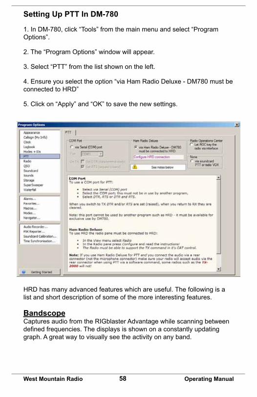
Setting Up PTT In DM-780
1. In DM-780, click “Tools” from the main menu and select “Program Options”.
2. The “Program Options” window will appear.
3. Select “PTT” from the list shown on the left.
4. Ensure you select the option “via Ham Radio Deluxe - DM780 must be connected to HRD”
5. Click on “Apply” and “OK” to save the new settings.
HRD has many advanced features which are useful. The following is a list and short description of some of the more interesting features.
Bandscope Captures audio from the RIGblaster Advantage while scanning between definedfrequencies.Thedisplaysisshownonaconstantlyupdatinggraph. A great way to visually see the activity on any band.

59West Mountain Radio Operating Manual
Rotator HRD provides a nice interface to many antenna rotors for automatic control.
Satellite Tracking HRD will automatically compensate for doppler-shift while tracking satellites.
IP Server Provides a TCP/IP interface for remote station control. Use HRD to control your radio from anywhere with an internet connection
DM780 Digital Master 780 is a very feature-rich digital-Mode program. Operate PSK31 and many other modes while integrating logging with Ham Radio Deluxe. Consider trying the “Super Browser” which will decode multiple PSK31 transmissions simultaneously.

60West Mountain Radio Operating Manual

61West Mountain Radio Operating Manual

62West Mountain Radio Operating Manual

63West Mountain Radio Operating Manual
Icom CI-V CAT Cable Schematic
Icom uses the same CI-V interface for nearly all their transceivers. This optional cable (SKU 58107-971) is available from West Mountain Radio for modest cost but we realize you may want to save a few dollars and make it yourself. Shown below is how the cable should be wired.
Note: A stereo 1/8” patch cable with a stereo-to-mono adapter will not work!

64West Mountain Radio Operating Manual
ISC & Jumper Wiring
Pattern #1: Kenwood, Alinco, Elecraft & SGC with 8 pin round-metal mic jack
ISC labeled “Kenwood 8 Pin Round Metal”
Pattern #2: Icom with 8 pin round-metal mic jack
ISC labeled “Icom 8 Pin Round Metal”

65West Mountain Radio Operating Manual
Pattern #3: Older Yaesu Radios with 8 pin round-metal mic jack
ISC labeled “Yaesu 8 Pin Round Metal”
(This jumpering is for older Yaesu radios with microphones that have common PTT & audio ground and older hand mics, desk mics, desk mics and Heil mics)
Pattern #4: Newer Yaesu Radios with 8 pin round-metal mic jack
ISC labeled “Yaesu 8 Pin Round – Isolated”. Use this for FT-950, FT-2000, FTDX-3K,5K,9K
(This ISC also used for Flex 6000 series, Ten Tec Omni VII & Orion II)

66West Mountain Radio Operating Manual
Pattern #5: Icom & Alinco Radios with RJ-45 modular mic jacks
ISC labeled “Icom RJ-45 Modular”
Pattern #6: Kenwoods with RJ45 mic jacks & most, but not all Kenwood FM rigs
ISC labeled “Kenwood RJ-45 Modular”

67West Mountain Radio Operating Manual
Pattern #7: Yaesu Radios with RJ45 mic jacks
ISC labeled “Yaesu RJ-45 Modular”
Use This ISC For FT-817, FT-857, FT-897 & FT-450.

68West Mountain Radio Operating Manual
Using RIGblaster Advantage As A Microphone Patch Box
It's perfectly possible to use the RIGblaster Advantage to interface a different brand microphone with your transceiver even if the pin outs are different. In this case you would not use one of the supplied ISCs – you would use the white and blue jumpers supplied.
If you examine the P1 jumper header you will see there are two sides – an “input” side and an “output” side. The “input” side corresponds to the front 8 pin round metal mic jack and the “output” side corresponds to the rear RJ-45 jack. Although labeled “input” & “output” the RIGblaster Advantage is bi-directional so a microphone can be connected to the front or rear (depending on mic plug).
In general, wire the side your transceiver is connected to with the radio mic jack pin out (found in the owner's manual) and then wire the opposite side to suit the microphone being used.
If your microphone has an 8 pin “round metal” plug then no criss-cross jumpers (PTT & MIC) are needed – just wire them to the same side.
If you are using a microphone with an RJ-45 plug then you will need to criss-cross the PTT & MIC jumpers i.e., connect them to the other side. Study patterns 5,6 & 7 to see examples of the criss-cross wiring.
If your radio uses a common ground for mic audio and PTT then a shunt jumper should be used on the GND TIE terminal. This ties together both of these grounds.
Be careful if the radio has a voltage output on the mic jack. You don't want to pass this through to an off-brand mic!
If there is no bias voltage available from the mic jack and you are using a condensor microphone, external bias will be required – some microphones provide this from internal batteries.
West Mountain Radio will not cover repair or replacement if you damage your equipment by incorrectly connecting jumpers!

69West Mountain Radio Operating Manual
Using the West Mountain Radio COM Port Spitter
Sometimes it is impossible or inconvenient to attempt CAT control, PTT and CW/FSK keying through a single Windows COM port.
For this reason we developed the COM Port Splitter application (part of the Diagnostic/Survey program).
It allows you to create either two or three virtual COM ports and map the CAT, PTT & CW/FSK functions.
For instance, using this software you can separate all three functions onto different COM port numbers. This could be used to operate HRD & DM-780 in RTTY FSK mode (with a suitable FSK cable).
You can also map PTT & FSK onto the same COM port (while keeping CAT separate). This could be used for N1MM Logger running MMTTY in RTTY FSK.

70West Mountain Radio Operating Manual
Using The P2 Jumper
Placing a jumper on P2 (2 pin header pointed to below) will attenuate transmittedaudiowhenfindingtheinputtothetransceiveristoo“hot”.Thefactory default position is open.

71West Mountain Radio Operating Manual
Digital-Modes, Software And Frequencies
A complete list of digital-modes, software and HF frequencies would be difficulttofind,however,belowisaabrief(non-exhaustive)compilationofsuggested frequencies to help get oriented with the RIGblaster Advantage.
MostfrequenciesgivenherereflectcurrentNorthAmericanpractices.Manyof these are shared internationally, but if in doubt, check with a national amateur radio organization for recommendations.
There are many Internet resources that provide further information on operating digital-Modes and a good place to start is K3UK’s Digital Radio Yahoo!® forum: http://groups.yahoo.com/group/digitalradio/
Digital Mode
Software Frequencies Notes
PSK31 Fldigi, Airlink Express, DM-780, Digipan, MixW, MultiPSK, TruTTY, WinWar-bler et al.
3.580 MHz (usb)7.035 MHz (usb)10.140 MHz (usb)14.070 MHz (usb)18.100 MHz (usb)21.070 MHz (usb)28.120 MHz (usb))
Analog SSTV
MMSSTV, MultiPSK, MixW 7.171Mhz (lsb)14.230Mhz (usb)
Digital SSTV
EasyPal 3.713MHz (lsb)7.173MHz (lsb)14.233MHz (usb)
RTTY MMTTY, TruTTY,DM780, FLdigi, MultiPSK et al
14.080-14.090MHz Traditional operating was in lsb but many today use usb
JT-65 WSJT, JT65-HF, MultiPSK 1.838MHz (usb)3.576MHz (usb)7.039MHz (usb)14.076MHz (usb)21.076MHz (usb)28.076MHz (usb)
Hellsch-reiber
FLdigi, MultiPSK, MixW, DM780
14.063 MHz (usb)14.073 MHz(usb)
Olivia FLdigi, MixW, MultiPSK, DM780
14.074MHz (usb)14.1065MHz (usb)
Digital Voice
Free DV 14.236 MHz (usb)
HF Packet Radio
Sound Modem, AGWPE, MultiPSK, MixW
14.1018 MHz (usb) Tones will be at 1400/1600Hz on the waterfall.
VHF APRS Sound Modem, AGWPE, MultiPSK, MixW
144.390 MHz (fm) International APRS frequencies vary.

72West Mountain Radio Operating Manual
Problem Cause FixNo power light showing (green LED)
1. USB cable is unplugged
2. Driver Issue
1. Check USB cable is connected.
2. Check Windows device-manager for RIGblaster Advantage COM port conflictsandre-installdrivers/change COM port if necessary.
Radio will not go into transmit
1. Incorrect ISC installed
2.Softwareconfiguration
1. Make sure the correct ISC (or jumper wiring) is installed for the transceiver in use.
2. Ensure the digital-mode software is set for RTS=PTT and DTR=CW.Note: RTS/DTR should never be set to permanently “high” or “on”.
Radio will enter transmit, but no power level showing
1. Incorrect ISC installed
2. Windows mixer volume sliders set too low
3. XMIT LEVEL control is too low
4. Transceiver MIC GAIN/RF POWER set too low
5. Wrong sound device selected
1. Make sure the correct ISC (or jumper wiring) is installed for the transceiver in use.
2. Ensure the Windows mixer (RIGblaster Audio) is set appropriately and not muted.
3. Rotate the XMIT LEVEL control slowly clockwise while transmitting and note if power out increases.
4. Check the transceiver’s MIC GAN and RF POWER controls are not set too low.
5. Make sure the digital mode program is using the RIGblaster Advantage Audio device and not the default sound-card.

73West Mountain Radio Operating Manual
Radio Control (CAT) not working
1. CAT cable unplugged
2. Software/Transceiver configuration
3. Noise
1. Connect the optional CAT cable.
2. Ensure the RIGblaster Advantage COM port is selected and the serial settings (baud rate etc) in the software match the transceiver. Some Yaesu radios have a multi-function port which must be enabled for CAT.
3. Some switching power supplies can cause prob-lems with CAT control. Ensure that equipment is properly grounded.
Waterfall not showing 1. Audio cable not con-nected
2. Windows recording mixer set too low
3. RCVE LEVEL control set too low
4. Wrong sound-device selected
1. Connect the audio cable from the radio to the RIG-blaster Advantage.
2. Ensure the recording level mixer for the Advan-tage is not muted and set appropriately.
3. Rotate RCVE LEVEL control until waterfall starts displaying normally.
4. Make sure the digital mode program is using the RIGblaster Advantage Audio device and not the default sound-card.
CW keying not working 1. CW keying cable not connected
2. Radio has wrong mode selected
3.Softwareconfiguration.
1. Connect the optional CW keying cable to the trans-ceiver’s CW input jack.
2. Serial port CW keying will only work in the transceiv-er’s CW mode.
3. Ensure the digital-mode software is set for RTS=PTT and DTR=CW.Note: RTS/DTR should never be set to permanently “high” or “on”.

74West Mountain Radio Operating Manual
Radio transmits but FSK RTTY not working
1. FSK cable not connected
2. Transceiver does not support FSK RTTY
3.Softwareconfiguration
4. Transceiver settings
1. Connect the optional FSK cable to the transceiv-er’s ACC/FSK jack.
2. Only radios with a dedicated RTTY mode can support FSK RTTY.
3. Ensure the software is set for RTS=PTT and DTR=FSK SHIFT.
4. Ensure the transceiver is configuredcorrectlyforFSKRTTY.
Radio stays in transmit after PTT activated
1. RFI 1. This is usually caused by RFI. Try re-positioning the RIGblaster Advantage away from your radio and tuner and ensure the equipment is properly grounded.
Transmitted audio is dis-torted
1. XMIT LEVEL control set too high
2. Windows mixer slider set too high
3. RFI
1. Rotate XMIT LEVEL control counter-clockwise until audio output is clean. In general your transceiver ALC meter should indicate minimum or no ALC action.
2. Reduce Windows volume sliders until audio in normal range. In general your transceiver ALC meter should indicate minimum or no ALC action.
3. Try re-positioning the RIGblaster Advantage away from your radio and tuner and ensure the equipment is properly grounded.

RIGblaster Advantage WarrantyRIGblaster Advantage is warranted against failure due to defects in workmanship or materials for one year after the date of purchase from West Mountain Radio. Warranty does not cover damage caused by abuse, accident, misuse, improper or abnormal usage, failure to follow instructions, improper installation, alteration, lightning, or other incidence of excessive voltage or current. If failure occurs within this period, return the RIGblaster Advantage or accessory to West Mountain Radio at your shipping expense. The device or accessory will be repaired or replaced, at our option, without charge, and returned to you at our shipping expense. Repaired or replaced items are warranted for the remainder of the original warranty period. You will be charged for repair or replacement of the RIGblaster Advantage or accessory made after the expiration of the warranty period.
The Compact Disc of Radio Amateur Software Collection is excluded from any and all warranties by West Mountain Radio. Note that the programs have been provided as shareware or freeware by the software authors to the amateur radio community for their use and enjoyment. The DVD is to be used at your own risk.
West Mountain Radio shall have no liability or responsibility to customer or any other person or entity with respect to any liability, loss, or damage caused directly or indirectly by use or performance of the products or arising out of any breach of this warranty, including, but not limited to, any damages resulting from inconvenience, loss of time, data, property, revenue, or profit, or any indirect, special incidental, or consequential damages, even if West Mountain Radio has been advised of such damages.
Except as provided herein, West Mountain Radio makes no express warranties and any implied warranties, including fitness for a particular purpose, are limited in duration to the stated duration provided herein. www.westmountainradio.com 1020 Spring City Drive, Waukesha, WI 53186 tel 262-522-6503 fax 262-522-6504