Skanska Scholarship at University of Portland Skanska USA - 2013.
DIKE
DIKEDIKE
CONC
DEPARTMENT OF TRANSPORTATION
PREPARED FOR THE
STATE OF CALIFORNIA
TI
ME
PL
OT
TE
D
=>
DA
TE
PL
OT
TE
D
=>
12:45:53
PM
12/19/2012
US
ER
NA
ME
=>
mozaffarianb
PROJECT ENGINEER
DESIGN OVERSIGHT
SIGN OFF DATE
DESIGN
DETAILS
QUANTITIES
BY CHECKED
SPECIFICATIONS
CHECKED
PLANS AND SPECS
COMPARED
BY
BY
LAYOUT
...\Governor\57-0759rl-a-gp01.dgnFILE =>
DISREGARD PRINTS BEARING
EARLIER REVISION DATES
BRIDGE NO.
SHEET OF
CHECKED
CHECKEDBY
BY
DIST COUNTY ROUTESHEET TOTAL
PLANS APPROVAL DATE
REGISTERED CIVIL ENGINEER
NoTOTAL PROJECT SHEETS
The State of California or its officers or agents
shall not be responsible for the accuracy or
POST MILES
ORIGINAL SCALE IN INCHES
FOR REDUCED PLANS0 1 2 3
POST MILES
DATE
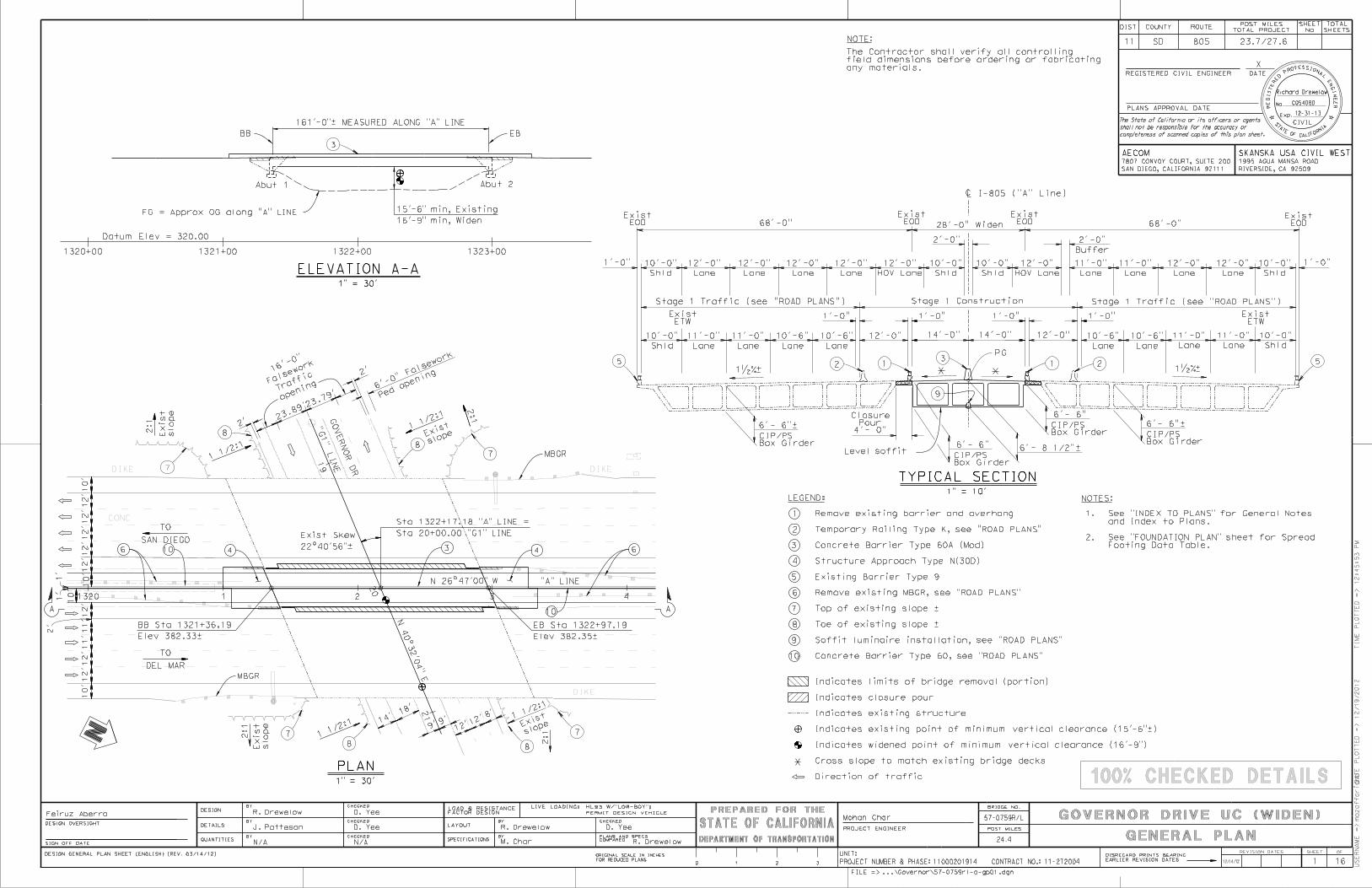
GENERAL PLAN
X
UNIT:
PROJECT NUMBER & PHASE:
X
No.
Exp.
CIVIL
RE
GIS
TE
RE
D P
ROFESSIONAL
E
NGI
NE
ER
S
TATE OF CALIF
ORNIA
REVISION DATES
FACTOR DESIGNLOAD & RESISTANCE LIVE LOADING: HL93 W/"LOW-BOY";
PERMIT DESIGN VEHICLE
CONTRACT NO.: 11-2T2004
11 SD 805
SAN DIEGO, CALIFORNIA 92111
7807 CONVOY COURT, SUITE 200
23.7/27.6
12-31-13
Richard Drewelow
C054080
11000201914
24.4
GOVERNOR DRIVE UC (WIDEN)57-0759R/LR. Drewelow
J. Patteson
N/A
R. Drewelow
R. Drewelow
AECOM
16
Mohan Char
M. Char
Feiruz Aberra
DESIGN GENERAL PLAN SHEET (ENGLISH) (REV. 03/14/12)
completeness of scanned copies of this plan sheet.
100% CHECKED DETAILS
RIVERSIDE, CA 92509
1995 AGUA MANSA ROAD
SKANSKA USA CIVIL WEST
12/14/12
PLAN
TYPICAL SECTION1" = 10’
1" = 30’
1" = 30’
1321+00 1322+001320+00 1323+00
Datum Elev = 320.00
BB EB
68’-0" 68’-0"
EODExist
EODExist
EODExist
EODExist
ETWExist
2
Box GirderCIP/PS
6’- 6"–
Box GirderCIP/PS
6’- 6"–
1�%–1�%–
1
2
3
4
1
161’-0"– MEASURED ALONG "A" LINE
Abut 1 Abut 2
1320 1 2 3 4
19
20
N 40°3
2’0
4" E
21
GO
VE
RN
OR
DR
Elev 382.33–
BB Sta 1321+36.19
Elev 382.35–
EB Sta 1322+97.19
Exist Skew
12’
SAN DIEGO
TO
DEL MAR
TO
10’12’12’11’11’12’
12’12’12’12’12’10’
MBGR
MBGR
14’
18’
2:1
2:1
NOTES:LEGEND:
5
6
Box GirderCIP/PS
Box GirderCIP/PS
5 5
PG
Shld
10’-0"
Shld
10’-0"ELEVATION A-A
2:1
1 1/
2:1
2:1
1 1/
2:1
9’9’
8’
12’
46 64
1 1/
2:1
1 1/
2:1
A A
6’- 6"
6’- 6"
7
8
*
3
4’- 0"Pour
Closure
* *
28’-0" Widen
2’
1’
1’
N 26°47’00" W "A" LINE
3
7
77
7
8
8
8 8
NOTE:
� I-805 ("A" Line)
Shld
10’-0"
Lane
11’-0"
Lane
11’-0"
Lane
10’-6"
Lane
10’-6"
Shld
10’-0"
Lane
11’-0"
Lane
11’-0"
213
Stage 1 Construction
ETWExist
Lane
12’-0"
Lane
12’-0"
Lane
12’-0"
Lane
12’-0"
HOV Lane
12’-0"
Shld
10’-0"
Shld
10’-0"
Lane
11’-0"
Lane
11’-0"1’-0" 1’-0"
HOV Lane
12’-0"
14’-0" 14’-0"
1’-0" 1’-0"
2’-0"
Buffer
2’-0"
12’-0"
1’-0"
12’-0"
1’-0"
Lane
10’-6"
Lane
10’-6"
Clearance Width
Vertical Horizontal Clear
Falsework opening required over
Railroad Traffic
Location Height Width
Falsework opening required on
Pedestrian Traffic
for footing excavation.
C. Temporary traffic lane reduction needed
Two-way
Bnd
Bnd
Clearance Opening
Temporary Vertical Width of Traffic
B. Falsework opening(s) required:
A. No falsework allowed over traffic.
4. Traffic will pass under the structure on
Stage construction will/will not be required.
3. Traffic will be carried on the structure.
2. Traffic will be detoured away from the site.
1. New alignment. No traffic at the site.
Vehicular Traffic
9
9
2’
2’
1
Stage 1 Traffic (see "ROAD PLANS") Stage 1 Traffic (see "ROAD PLANS")
10’
10’
Direction of traffic
Cross slope to match existing bridge decks
Indicates widened point of minimum vertical clearance (16’-9")
Indicates existing structure
Indicates closure pour
Indicates limits of bridge removal (portion)
any materials.
field dimensions before ordering or fabricating
The Contractor shall verify all controlling
N/A
D. Yee
D. Yee D. Yee
FG = Approx OG along "A" LINE
16’-9" min, Widen
15’-6" min, Existing
Level soffit
10
Footing Data Table.
See "FOUNDATION PLAN" sheet for Spread2.
and Index to Plans.
See "INDEX TO PLANS" for General Notes1.
10
10
slope
Exist
slop
eExist
slope
Exist
slop
eExist
Ped
openin
g
6’-0
" Fals
ework
openin
gTr
affi
cFals
ework16
’-0"
23.8
9’23.7
9’
Concrete Barrier Type 60, see "ROAD PLANS"
Soffit luminaire installation, see "ROAD PLANS"
Remove existing MBGR, see "ROAD PLANS"
Existing Barrier Type 9
Structure Approach Type N(30D)
Concrete Barrier Type 60A (Mod)
Temporary Railing Type K, see "ROAD PLANS"
Remove existing barrier and overhang
"G1"
LI
NE
Sta 20+00.00 "G1" LINE
Sta 1322+17.18 "A" LINE =
Lane
12’-0"
Lane
12’-0"

DEPARTMENT OF TRANSPORTATION
PREPARED FOR THE
STATE OF CALIFORNIA
TI
ME
PL
OT
TE
D
=>
DA
TE
PL
OT
TE
D
=>
9:30:56
AM
12/18/2012
US
ER
NA
ME
=>
pattesonj
PROJECT ENGINEER
DESIGN OVERSIGHT
SIGN OFF DATE
...\Governor\57-0759rl-a-itp.dgnFILE =>
DISREGARD PRINTS BEARING
EARLIER REVISION DATES
BRIDGE NO.
SHEET OF
DIST COUNTY ROUTESHEET TOTAL
PLANS APPROVAL DATE
REGISTERED CIVIL ENGINEER
NoTOTAL PROJECT SHEETS
The State of California or its officers or agents
shall not be responsible for the accuracy or
POST MILES
ORIGINAL SCALE IN INCHES
FOR REDUCED PLANS0 1 2 3
POST MILES
DATE
X
UNIT:
PROJECT NUMBER & PHASE:
X
DESIGN
DETAILS
QUANTITIES
BY CHECKED
CHECKED
CHECKEDBY
BY
No.
Exp.
CIVIL
RE
GIS
TE
RE
D P
ROFESSIONAL
E
NGI
NE
ER
S
TATE OF CALIF
ORNIA
REVISION DATES
CONTRACT NO.:
11 SD 805 23.7/27.6
Richard Drewelow
C054080
12-31-13
24.4
11-2T200411000201914
GOVERNOR DRIVE UC (WIDEN)57-0759R/LR. Drewelow
J. Patteson
16
Feiruz AberraMohan Char
N/A
DESIGN DETAIL SHEET (ENGLISH) (REV. 03/14/12)
completeness of scanned copies of this plan sheet.
D. Yee
D. Yee
N/A
100% CHECKED DETAILS
SAN DIEGO, CALIFORNIA 92111
7807 CONVOY COURT, SUITE 200
AECOM
RIVERSIDE, CA 92509
1995 AGUA MANSA ROAD
SKANSKA USA CIVIL WEST
12/14/12
INDEX TO PLANS
INDEX TO PLANSSTANDARD PLANS MAY 2006
CONCRETE STRENGTH AND TYPE LIMITS
No Scale
SITE SPECIFIC ARS CURVE
0.0 0.5 1.0 1.5 2.0 2.5 3.0 3.5 4.0
0.0
0.1
0.2
0.3
0.4
0.5
0.6
0.7
0.8
0.9
1.0
Period (Seconds)
Spectral
Acc. (g)
STANDARD PLAN SHEET NO.
DETAIL NO.
2
S30
LOG OF TEST BORINGS (5 OF 5)16.
LOG OF TEST BORINGS (4 OF 5)15.
LOG OF TEST BORINGS (3 OF 5)14.
LOG OF TEST BORINGS (2 OF 5)13.
LOG OF TEST BORINGS (1 OF 5)12.
STRUCTURE APPROACH DRAINAGE DETAILS11.
STRUCTURE APPROACH TYPE N(30D)10.
GIRDER REINFORCEMENT9.
GIRDER LAYOUT8.
TYPICAL SECTION7.
ABUTMENT DETAILS6.
ABUTMENT LAYOUT5.
REMOVAL PLAN4.
FOUNDATION PLAN3.
INDEX TO PLANS2.
GENERAL PLAN1.
max
CONCRETE:
See "Prestressing Notes" on "GIRDER LAYOUT" sheetPRESTRESSED
n = 8
f’c = 3.6 ksi, unless noted otherwise
fy = 60 ksiCONCRETE:
ASTM A706REINFORCED
LOADING:
Site Specific ARS CurveSEISMIC
Permit design loadLOADING:
HL-93 Design Truck and Tandem and P15LIVE
Includes 35 psf for future wearing surfaceDEAD LOAD:
November 2010DESIGN:
Caltrans Seismic Design Criteria (SDC) version 1.6SEISMIC
with California amendments dated December 15, 2011
AASHTO LRFD Bridge Design Specifications 4TH EditionDESIGN:
LOAD AND RESISTANCE FACTOR DESIGN
GENERAL NOTES
(f’c = 3.6 ksi @ 28 days)
Structural Concrete, Approach Slab
(f’c = 4 ksi @ 28 days)
Structural Concrete, Bridge Footing
(f’c = 6 ksi @ 28 days)
Structural Concrete, Bridge
(f’c = 4 ksi @ 28 days)
Structural Concrete, Bridge
V = 1300 ft/sSoil Profile:
5% Damping
Moment Magnitude, M
= 0.42 gPeak Ground Acceleration
ISOLATION JOINT DETAIL
CONCRETE PAVEMENT - LANE SCHEMATICS ANDRSP P18
CONCRETE PAVEMENT - DOWEL BAR DETAILSRSP P10
CAST-IN-PLACE PRESTRESSED GIRDER DETAILSB8-5
BOX GIRDER DETAILSB7-1
JOINT SEALS (MAXIMUM MOVEMENT RATING = 2")RSP B6-21
BRIDGE DETAILSB0-13
BRIDGE DETAILSB0-5
BRIDGE DETAILSB0-3
BRIDGE DETAILSB0-1
CONCRETE BARRIER TYPE 60RSP A76A
SYMBOLS (SHEET 2 OF 2)A10D
SYMBOLS (SHEET 1 OF 2)A10C
ACRONYMS AND ABBREVIATIONS (SHEET 2 OF 2)A10B
ACRONYMS AND ABBREVIATIONS (SHEET 1 OF 2)A10A
DIKEDIKE
380
380
370
378.9
379.4
DEPARTMENT OF TRANSPORTATION
PREPARED FOR THE
STATE OF CALIFORNIA
TI
ME
PL
OT
TE
D
=>
DA
TE
PL
OT
TE
D
=>
12:45:58
PM
12/19/2012
US
ER
NA
ME
=>
mozaffarianb
PROJECT ENGINEER
DESIGN OVERSIGHT
SIGN OFF DATE
...\Governor\57-0759rl-e-fpl01.dgnFILE =>
DISREGARD PRINTS BEARING
EARLIER REVISION DATES
BRIDGE NO.
SHEET OF
DIST COUNTY ROUTESHEET TOTAL
PLANS APPROVAL DATE
REGISTERED CIVIL ENGINEER
NoTOTAL PROJECT SHEETS
The State of California or its officers or agents
shall not be responsible for the accuracy or
POST MILES
ORIGINAL SCALE IN INCHES
FOR REDUCED PLANS0 1 2 3
POST MILES
DATE
X
UNIT:
PROJECT NUMBER & PHASE:
X
DESIGN
DETAILS
QUANTITIES
BY CHECKED
CHECKED
CHECKEDBY
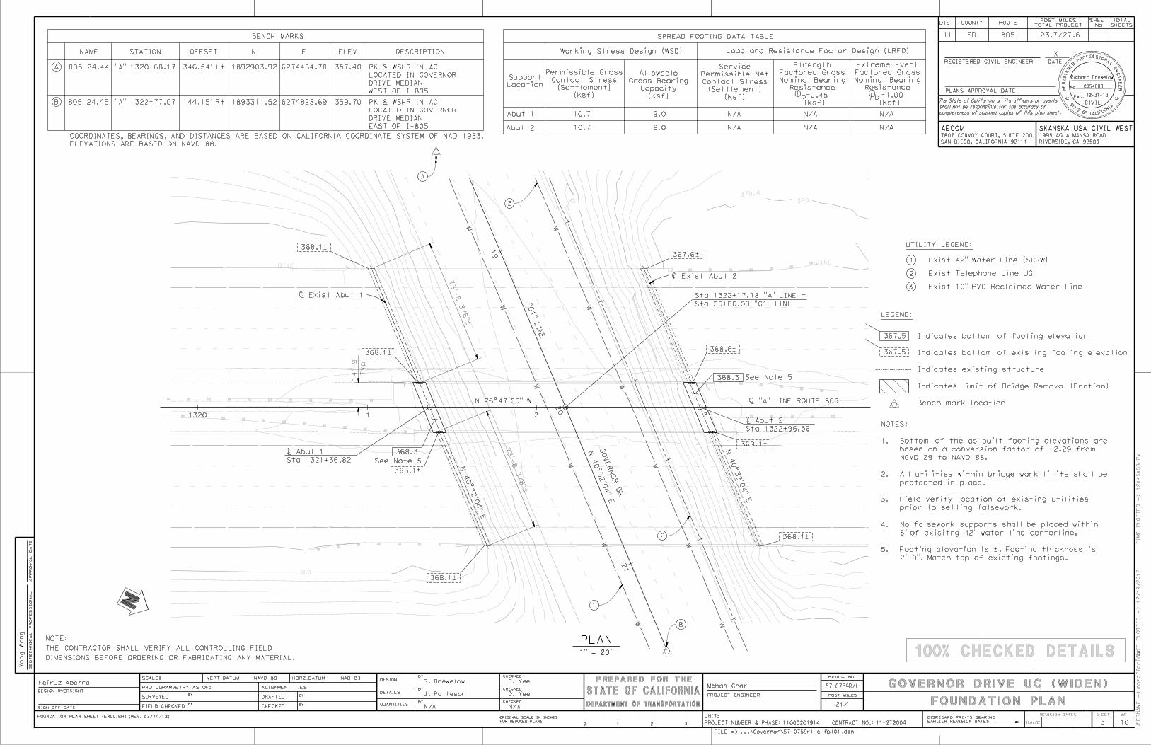
BY FOUNDATION PLAN
GE
OT
EC
HNIC
AL
PR
OF
ES
SI
ON
AL
AP
PR
OV
AL
DA
TE
PHOTOGRAMMETRY AS OF:
SURVEYEDBY
BYCHECKED
DRAFTEDBY
BYFIELD CHECKED
ALIGNMENT TIES
SCALE: VERT.DATUM HORZ.DATUM
No.
Exp.
CIVIL
RE
GIS
TE
RE
D P
ROFESSIONAL
E
NGI
NE
ER
S
TATE OF CALIF
ORNIA
REVISION DATES
CONTRACT NO.:
11 SD 805 23.7/27.6
Richard Drewelow
C054080
12-31-13
24.4
11-2T200411000201914
GOVERNOR DRIVE UC (WIDEN)57-0759R/LR. Drewelow
J. Patteson
N/A
Feiruz AberraMohan Char
16
Yong
Wang
FOUNDATION PLAN SHEET (ENGLISH) (REV. 03/14/12)
completeness of scanned copies of this plan sheet.
N/A
D. Yee
D. Yee
NAVD 88 NAD 83
100% CHECKED DETAILS
SAN DIEGO, CALIFORNIA 92111
7807 CONVOY COURT, SUITE 200
AECOM
RIVERSIDE, CA 92509
1995 AGUA MANSA ROAD
SKANSKA USA CIVIL WEST
12/14/12
PLAN
GO
VE
RN
OR
DR
Typ
14’-9"
N 40°3
2’0
4" E
N 40°3
2’0
4" E
1
2
3
N 26°47’00" W
3
2
1" = 20’
1
1320 1 2 3
19
20
21
N 40°3
2’0
4" E
Abut 2
Abut 1
(ksf)
(Settlement)
Contact Stress
Permissible Net
Service
Location
Support
(ksf)
(Settlement)
Contact Stress
Permissible Gross
(ksf)
Capacity
Gross Bearing
Allowable
Working Stress Design (WSD) Load and Resistance Factor Design (LRFD)
SPREAD FOOTING DATA TABLE
(ksf)
=1.00
Resistance
Nominal Bearing
Factored Gross
Extreme Event
b
N/A N/A N/A
N/AN/AN/A
368.3
368.3
� "A" LINE ROUTE 805
LEGEND:
367.5
3
10.7
10.7
9.0
9.0
367.5
368.1–
368.1–
368.1–
368.1–
367.6–
368.6–
369.1–
368.1–
Sta 1321+36.82
� Abut 1
Sta 1322+96.56
� Abut 2
DIMENSIONS BEFORE ORDERING OR FABRICATING ANY MATERIAL.
THE CONTRACTOR SHALL VERIFY ALL CONTROLLING FIELD
NOTE:
UTILITY LEGEND:
Exist 10" PVC Reclaimed Water Line
Exist Telephone Line UG
Exist 42" Water Line (SCRW)
(ksf)
=0.45
Resistance
Nominal Bearing
Factored Gross
Strength
b
� Exist Abut 2
� Exist Abut 1
A
STATION
B
ELEVATIONS ARE BASED ON NAVD 88.
COORDINATES, BEARINGS, AND DISTANCES ARE BASED ON CALIFORNIA COORDINATE SYSTEM OF NAD 1983.
OFFSET N
1892903.92
1893311.52 6274828.69
6274484.78
E ELEV
357.40
359.70
DESCRIPTION
BENCH MARKS
"A" 1320+68.17 346.54’ Lt
144.15’ Rt"A" 1322+77.07
NAME
805 24.44
805 24.45
WEST OF I-805
DRIVE MEDIAN
LOCATED IN GOVERNOR
PK & WSHR IN AC
EAST OF I-805
DRIVE MEDIAN
LOCATED IN GOVERNOR
PK & WSHR IN AC
A
B
Bench mark location
Indicates limit of Bridge Removal (Portion)
Indicates existing structure
Indicates bottom of existing footing elevation
Indicates bottom of footing elevation
See Note 5
See Note 5
2’-9". Match top of existing footings.
5.
8’ of exisitng 42" water line centerline.
No falsework supports shall be placed within4.
prior to setting falsework.
Field verify location of existing utilities3.
protected in place.
All utilities within bridge work limits shall be2.
NGVD 29 to NAVD 88.
based on a conversion factor of +2.29 from
Bottom of the as built footing elevations are1.
NOTES:
"G1" LIN
E
Sta 20+00.00 "G1" LINE
Sta 1322+17.18 "A" LINE =

DEPARTMENT OF TRANSPORTATION
PREPARED FOR THE
STATE OF CALIFORNIA
TI
ME
PL
OT
TE
D
=>
DA
TE
PL
OT
TE
D
=>
9:31:01
AM
12/18/2012
US
ER
NA
ME
=>
pattesonj
PROJECT ENGINEER
DESIGN OVERSIGHT
SIGN OFF DATE
...\57-0759rl-e-rem_pl.dgnFILE =>
DISREGARD PRINTS BEARING
EARLIER REVISION DATES
BRIDGE NO.
SHEET OF
DIST COUNTY ROUTESHEET TOTAL
PLANS APPROVAL DATE
REGISTERED CIVIL ENGINEER
NoTOTAL PROJECT SHEETS
The State of California or its officers or agents
shall not be responsible for the accuracy or
POST MILES
ORIGINAL SCALE IN INCHES
FOR REDUCED PLANS0 1 2 3
POST MILES
DATE
X
UNIT:
PROJECT NUMBER & PHASE:
X
DESIGN
DETAILS
QUANTITIES
BY CHECKED
CHECKED
CHECKEDBY
BY
No.
Exp.
CIVIL
RE
GIS
TE
RE
D P
ROFESSIONAL
E
NGI
NE
ER
S
TATE OF CALIF
ORNIA
REVISION DATES
CONTRACT NO.:
11 SD 805 23.7/27.6
Richard Drewelow
C054080
12-31-13
24.4
11-2T200411000201914
GOVERNOR DRIVE UC (WIDEN)57-0759R/LR. Drewelow
J. Patteson
16
Feiruz AberraMohan Char
N/A
DESIGN DETAIL SHEET (ENGLISH) (REV. 03/14/12)
completeness of scanned copies of this plan sheet.
D. Yee
D. Yee
N/A
100% CHECKED DETAILS
SAN DIEGO, CALIFORNIA 92111
7807 CONVOY COURT, SUITE 200
AECOM
RIVERSIDE, CA 92509
1995 AGUA MANSA ROAD
SKANSKA USA CIVIL WEST
12/14/12
REMOVAL PLAN
ABUTMENT REMOVAL ELEVATION
SECTION C-C
SECTION B-B
ABUTMENT REMOVAL PLAN
(Abut 1 shown, Abut 2 similar)
DIMENSIONS BEFORE ORDERING OR FABRICATING ANY MATERIAL.
THE CONTRACTOR SHALL VERIFY ALL CONTROLLING FIELD
NOTE:
(Abut 1 shown, Abut 2 similar)
LEGEND
(Exist Br No. 57-0759R)
Exist edge of deck
(Exist Br No. 57-0759L)
Exist edge of deck
C B
BC
footing
Edge of Exist
footing
Edge of ExistAbutment
� Exist
= � Exist footing
� Exist Abutment
4
NOTES:
See Note 1
abutment diaphragm
Edge of existing
exterior girder
Edge of existing
exterior girder
Edge of existing
abutment diaphragm
Edge of existing
See Note 2
See Note 2
1/4" = 1’-0"
1/4" = 1’-0"
1/4" = 1’-0"
Indicates existing structure
Bridge Removal (Portion)
Indicates limit of
and protect in place.
Existing footing reinforcement clean3.
clean and protect in place.
Existing transverse deck reinforcement 2.
storage facility.
and delivered to a Caltrans Department
railing to be removed shall be salvaged
All metal components of existing bridge1.
C
C
wallCurtain
1/4" = 1’-0"
SECTION D-D
B
B
Curtain wall
D
D
Exist wingwall
shear key
Top of existing
See Note 3footing
Top of existing
Edge of curtain wall
Abutment
� ExistEdge of curtain wall
Varies
1/4" = 1’-0"

DEPARTMENT OF TRANSPORTATION
PREPARED FOR THE
STATE OF CALIFORNIA
TI
ME
PL
OT
TE
D
=>
DA
TE
PL
OT
TE
D
=>
9:31:02
AM
12/18/2012
US
ER
NA
ME
=>
pattesonj
PROJECT ENGINEER
DESIGN OVERSIGHT
SIGN OFF DATE
...\57-0759rl-f-a01_lo.dgnFILE =>
DISREGARD PRINTS BEARING
EARLIER REVISION DATES
BRIDGE NO.
SHEET OF
DIST COUNTY ROUTESHEET TOTAL
PLANS APPROVAL DATE
REGISTERED CIVIL ENGINEER
NoTOTAL PROJECT SHEETS
The State of California or its officers or agents
shall not be responsible for the accuracy or
POST MILES
ORIGINAL SCALE IN INCHES
FOR REDUCED PLANS0 1 2 3
POST MILES
DATE
X
UNIT:
PROJECT NUMBER & PHASE:
X
DESIGN
DETAILS
QUANTITIES
BY CHECKED
CHECKED
CHECKEDBY
BY
No.
Exp.
CIVIL
RE
GIS
TE
RE
D P
ROFESSIONAL
E
NGI
NE
ER
S
TATE OF CALIF
ORNIA
REVISION DATES
CONTRACT NO.:
11 SD 805 23.7/27.6
Richard Drewelow
C054080
12-31-13
24.4
11-2T200411000201914
GOVERNOR DRIVE UC (WIDEN)57-0759R/LR. Drewelow
J. Patteson
16
Feiruz AberraMohan Char
N/A
DESIGN DETAIL SHEET (ENGLISH) (REV. 03/14/12)
completeness of scanned copies of this plan sheet.
D. Yee
D. Yee
N/A
100% CHECKED DETAILS
SAN DIEGO, CALIFORNIA 92111
7807 CONVOY COURT, SUITE 200
AECOM
RIVERSIDE, CA 92509
1995 AGUA MANSA ROAD
SKANSKA USA CIVIL WEST
12/14/12
LEGEND
DIMENSIONS BEFORE ORDERING OR FABRICATING ANY MATERIAL.
THE CONTRACTOR SHALL VERIFY ALL CONTROLLING FIELD
NOTE:
ABUTMENT LAYOUT
See Note 3
ABUTMENT PLAN
ABUTMENT ELEVATION
ABUTMENT FOOTING LAYOUT
7’-0"
3’-2"
1’-11"
1’-11"
New footing
Typ see Note 4
3" drain pipe,
See Note 3
Detail B, see Note 2
match Exist
Top of slope to
pour, Typ
Deck closure
See Note 3
� New Abut
4"
5
Shear key
face of existing abutments
Face of new abutment to match
(optional)
Const Jt
= � Shear key
= � Abut
I-805 ("A" LINE)
Indicates existing structure
Indicates closure pour
Bridge Removal (Portion)
Indicates limit of
Bearing pad Tot 43
Equal
spac
es @
9’-6
" =
28’-
6"
pour, Typ
Abutment closure
11"10"
13
Exist WW LOL
Exist EOD and
BB
Exist WW LOL
Exist EOD and
Edge of footing
of abut
Back face
pad 15" x 30" x 3"
or fabric reinforced bearing
14" x 26" x 2 1/2" (elastomer only)
Steel reinforcement bearing pad
EQ EQ
EQ
EQ
Level
Typ
3"
� Bearing pad = � Abut
BEARING PAD DETAIL
No Scale
1/4" = 1’-0"
FOOTING REINFORCING DETAIL
No Scale
See Note 1
1/4" = 1’-0"
See Note 1
1/4" = 1’-0"
� Exist Abut
hole, Typ
abutment in 10" deep
dowels @ 12" on � existing
drill and bond#5
� Exist Abut
� New Abut
"A" LINE
� Exist Abut
Extend abutment reinf into closure pour. Typ.6.
Match top of existing footings.5.
See "STRUCTURE APPROACH DRAINAGE DETAILS" sheet.4.
See "REMOVAL PLAN" sheet.3.
"ABUTMENT DETAILS" sheet.
For abutments sections and details, see2.
Abutment 1 is shown. Abutment 2 is similar.1.
NOTES:
See Note 5
See Note 6
4’-9
"

DEPARTMENT OF TRANSPORTATION
PREPARED FOR THE
STATE OF CALIFORNIA
TI
ME
PL
OT
TE
D
=>
DA
TE
PL
OT
TE
D
=>
9:31:04
AM
12/18/2012
US
ER
NA
ME
=>
pattesonj
PROJECT ENGINEER
DESIGN OVERSIGHT
SIGN OFF DATE
...\Governor\57-0759rl-f-a01dt.dgnFILE =>
DISREGARD PRINTS BEARING
EARLIER REVISION DATES
BRIDGE NO.
SHEET OF
DIST COUNTY ROUTESHEET TOTAL
PLANS APPROVAL DATE
REGISTERED CIVIL ENGINEER
NoTOTAL PROJECT SHEETS
The State of California or its officers or agents
shall not be responsible for the accuracy or
POST MILES
ORIGINAL SCALE IN INCHES
FOR REDUCED PLANS0 1 2 3
POST MILES
DATE
X
UNIT:
PROJECT NUMBER & PHASE:
X
DESIGN
DETAILS
QUANTITIES
BY CHECKED
CHECKED
CHECKEDBY
BY
No.
Exp.
CIVIL
RE
GIS
TE
RE
D P
ROFESSIONAL
E
NGI
NE
ER
S
TATE OF CALIF
ORNIA
REVISION DATES
CONTRACT NO.:
11 SD 805 23.7/27.6
Richard Drewelow
C054080
12-31-13
24.4
11-2T200411000201914
GOVERNOR DRIVE UC (WIDEN)57-0759R/LR. Drewelow
J. Patteson
16
Feiruz AberraMohan Char
N/A
DESIGN DETAIL SHEET (ENGLISH) (REV. 03/14/12)
completeness of scanned copies of this plan sheet.
D. Yee
D. Yee
N/A
100% CHECKED DETAILS
SAN DIEGO, CALIFORNIA 92111
7807 CONVOY COURT, SUITE 200
AECOM
RIVERSIDE, CA 92509
1995 AGUA MANSA ROAD
SKANSKA USA CIVIL WEST
12/14/12
DIMENSIONS BEFORE ORDERING OR FABRICATING ANY MATERIAL.
THE CONTRACTOR SHALL VERIFY ALL CONTROLLING FIELD
NOTE:
No Scale
No Scale
ABUTMENT SECTION
END DIAPHRAGM DETAIL
DETAIL A DETAIL B
ABUTMENT DETAILS
Polystyrene
1" Expanded
3’-0"
footing
Top of
Abutment Reinf
Footing Reinf
#5 Tot 2
1’-6"
1’-6"2’-6"
1’-0"
2’-0"
1’-7" 1’-7"
B8-5
"ABUTMENT SECTION".
NOTE: For reinforcement not shown, see
"END DIAPHRAGM DETAIL".
NOTE: For reinforcement not shown, see
2’-9"
Clr
3"
Exist
Match
#5 @ 12"
#8 @ 12"
3’-2"
Exist
Match
(optional)
Const Jt
B6-21
(Match Exist)
BB/EB
#5 Tot 2
#5 Tot 2
7"1’-0"
4" Fillet
8’-0"
between girders
#5 @ 6"
Limits of distribution Reinf
Exist
Match
6
B0-1
1-6
footing
Top of
B0-1
1-6
7’-0"
2’-0"
Mi
n
filler, Typ
1" Exp Jt
(optional)
Const Jt
� Shear key
(optional)
Const Jt
NOTE: Abut 1 shown, Abut 2 similiar
#5 @ 12"
#7 @ 12"
grillage
recess and
anchorage
Prestressed
Detail A
sheet
APPROACH TYPE N(30D)"
See "STRUCTURE
Center on shear key
#11 x 14’-0" Tot 3
#11 Tot 3
3" Expanded Polystyrene
Typ
2" Clr
6"3’-3"
@ 12#5
6"
#5 @ 12"
2’-0"
3’-6"
3’-3"
Clr
2"
#5 Tot 8
#11 Tot 6
alternate
and 24" Horiz
#5 @ 12" Vert
neoprene with grease.
bearing. Coat top of
metal on top of each
20" x 32" x 16 Ga sheet
Polystyrene
3" Expanded
See Note 3
No Scale
See Note 3
1/2" = 1’-0"
#6 Tot 2
� Abut
� Abut
(MR = 1")
Joint Seal
see Note 1
Geocomposite Drain,
Pervious backfill or
see Note 1
Drain pipe,
#11
abutment. Place abutment bars perpendicular to abutment centerline.
Abutment dimensions are perpendicular or parallel to centerline of3.
than 2’-0" differential in backfill heights between each abutment.
Backfill shall be placed simultaneously at both abutments with no more
Abutment backfill shall be placed after completion of superstructure.2.
For drainage details, see "STRUCTURE APPROACH DRAINAGE DETAILS" sheet.1.
NOTES:

DEPARTMENT OF TRANSPORTATION
PREPARED FOR THE
STATE OF CALIFORNIA
TI
ME
PL
OT
TE
D
=>
DA
TE
PL
OT
TE
D
=>
9:31:05
AM
12/18/2012
US
ER
NA
ME
=>
pattesonj
PROJECT ENGINEER
DESIGN OVERSIGHT
SIGN OFF DATE
...\Governor\57-0759rl-k-ts01.dgnFILE =>
DISREGARD PRINTS BEARING
EARLIER REVISION DATES
BRIDGE NO.
SHEET OF
DIST COUNTY ROUTESHEET TOTAL
PLANS APPROVAL DATE
REGISTERED CIVIL ENGINEER
NoTOTAL PROJECT SHEETS
The State of California or its officers or agents
shall not be responsible for the accuracy or
POST MILES
ORIGINAL SCALE IN INCHES
FOR REDUCED PLANS0 1 2 3
POST MILES
DATE
X
UNIT:
PROJECT NUMBER & PHASE:
X
DESIGN
DETAILS
QUANTITIES
BY CHECKED
CHECKED
CHECKEDBY
BY
No.
Exp.
CIVIL
RE
GIS
TE
RE
D P
ROFESSIONAL
E
NGI
NE
ER
S
TATE OF CALIF
ORNIA
REVISION DATES
CONTRACT NO.:
11 SD 805 23.7/27.6
Richard Drewelow
C054080
12-31-13
24.4
11-2T200411000201914
GOVERNOR DRIVE UC (WIDEN)57-0759R/LR. Drewelow
J. Patteson
16
Feiruz AberraMohan Char
N/A
DESIGN DETAIL SHEET (ENGLISH) (REV. 03/14/12)
completeness of scanned copies of this plan sheet.
D. Yee
D. Yee
N/A
100% CHECKED DETAILS
SAN DIEGO, CALIFORNIA 92111
7807 CONVOY COURT, SUITE 200
AECOM
RIVERSIDE, CA 92509
1995 AGUA MANSA ROAD
SKANSKA USA CIVIL WEST
12/14/12
DIMENSIONS BEFORE ORDERING OR FABRICATING ANY MATERIAL.
THE CONTRACTOR SHALL VERIFY ALL CONTROLLING FIELD
NOTE:
LEGEND
TYPICAL SECTION
2’-0"
Typ
Pour
Closure
4’-0"
A76A
Typ
4’-0"
Br No. 57-0785L Br No. 57-0785R
and deck overhang
Remove Exist Type 9 Barrier
1.5%–1.5%–
Exist
Match
Exist
Match
Typ
8 1/8"
Typ
1’-0"
groove, Typ
3/4" Drip
Typ
4" fillet,
4" Typ6" Typ
Typ
1’-0"
1’-1"
Const Jt, Typ
Tot 8, Typ
#5 Cont
Typ
Half space
Typ
Half space
B7-1
B-1
#5 @ 12" Max, Typ
per girder, Typ
#8 Cont Tot 2
See Note 2
per girder, Typ
#5 Cont Tot 2
1"
Clr
2"
Clr
#4 Cont @ 18"
See Note 3
#6 or stirrups, Typ
per girder
#11 Cont Tot 2
#5 @ 10", Typ
1’-6"
B0-5
5-10
B0-5
5-11
PART TYPICAL SECTION
TYPICAL SECTION
B0-5 B7-1 B8-5
B0-5
5-2
#5, S=10" or
7
Typ
6"
3 Equal spaces @ 8’-9 5/16" = 26’-4"
1’-1"
Equal spaces, Typ
#5 Tot 8
1’-1"
Typ
per bay, Typ
#4 Tot 4
per bay, Typ
#5 Tot 7
MEDIAN WIDEN
-
See Note 1
NOTES:
camber values are 0.75 times those shown.
When Falsework Release Alternative 2 is used,
after the falsework has been released.
pour shall not be placed sooner than 14 days
after the last concrete has been placed. Closure
Falsework shall not be released less than 28 days
Alternate 2:
has been released.
placed sooner than 60 days after the falsework
by the specifications. Closure pour shall not be
Falsework shall be released as soon as permitted
Alternate 1:
FALSEWORK RELEASE & CLOSURE POUR
� I-805 ("A" LINE)
in place, typ
clean and protect
Reinf (S=10")
Exist #5 deck
CLOSURE POUR REINFORCING
Closure Pour
4’-0"
reinf
transverse
Existing
for reinf not shown
"PART TYPICAL SECTION"
#5 cont see
girder
Face of new
reinf
New transverse
2"closure pour
ties right before the
reinf with tight wire
Secure exist and new
complete.
Barrier may be placed after closure pours are7.
dowels as approved by Engineer.
Contractor shall be replaced by drill and bond
Any existing reinforcement damaged by6.
"Service" spliced.
Continuous longitudinal reinforcement shall be5.
all existing transverse deck reinforcement.
Remove deck along a straight line and protect4.
For stirrup spacing, see "GIRDER LAYOUT" sheet.3.
"GIRDER REINFORCEMENT" sheet.
For additional longitudinal reinforcement, see2.
For soffit lighting, see "ROAD PLANS".1.
Clr
1 1/2"
1"
Clr
Min
6’- 6"
1/4" = 1’-0"
1/2" = 1’-0"
staggered Typ
in 10" deep hole,
Drill and bond dowels
#53
110
"1’-9"
1/2" = 1’-0"
DRILL AND BOND DETAIL
See Note 6
1’-9"
Typ
#4 @ 13"
Indicates limit of Bridge Removal (Portion)
Indicates existing structure
(Mod)
Type 60A
Conc barrier
bond in 5" deep hole, see Note 7
6" min embedment or drill and
Wet set #5 @ 12" with
1/2" = 1’-0"

DEPARTMENT OF TRANSPORTATION
PREPARED FOR THE
STATE OF CALIFORNIA
TI
ME
PL
OT
TE
D
=>
DA
TE
PL
OT
TE
D
=>
9:31:06
AM
12/18/2012
US
ER
NA
ME
=>
pattesonj
PROJECT ENGINEER
DESIGN OVERSIGHT
SIGN OFF DATE
...\57-0759rl-l-gir_lo01.dgnFILE =>
DISREGARD PRINTS BEARING
EARLIER REVISION DATES
BRIDGE NO.
SHEET OF
DIST COUNTY ROUTESHEET TOTAL
PLANS APPROVAL DATE
REGISTERED CIVIL ENGINEER
NoTOTAL PROJECT SHEETS
The State of California or its officers or agents
shall not be responsible for the accuracy or
POST MILES
ORIGINAL SCALE IN INCHES
FOR REDUCED PLANS0 1 2 3
POST MILES
DATE
X
UNIT:
PROJECT NUMBER & PHASE:
X
DESIGN
DETAILS
QUANTITIES
BY CHECKED
CHECKED
CHECKEDBY
BY
No.
Exp.
CIVIL
RE
GIS
TE
RE
D P
ROFESSIONAL
E
NGI
NE
ER
S
TATE OF CALIF
ORNIA
REVISION DATES
CONTRACT NO.:
11 SD 805 23.7/27.6
Richard Drewelow
C054080
12-31-13
24.4
11-2T200411000201914
GOVERNOR DRIVE UC (WIDEN)57-0759R/LR. Drewelow
J. Patteson
16
Feiruz AberraMohan Char
N/A
DESIGN DETAIL SHEET (ENGLISH) (REV. 03/14/12)
completeness of scanned copies of this plan sheet.
D. Yee
D. Yee
N/A
100% CHECKED DETAILS
SAN DIEGO, CALIFORNIA 92111
7807 CONVOY COURT, SUITE 200
AECOM
RIVERSIDE, CA 92509
1995 AGUA MANSA ROAD
SKANSKA USA CIVIL WEST
12/14/12
DIMENSIONS BEFORE ORDERING OR FABRICATING ANY MATERIAL.
THE CONTRACTOR SHALL VERIFY ALL CONTROLLING FIELD
NOTE:
LEGEND
GIRDER LAYOUT
points shown
cable path is a parabola between
Center of gravity of prestress� Span
3" 3"
LONGITUDINAL SECTION
for "CAMBER DIAGRAM".
See "GIRDER REINFORCEMENT" sheetNOTE:B7-1
18
18 12
12
1812
1812
B7-1
V-1
Deck closure pour
Deck closure pour
4’-10"
4’-10"
"A" Line
@ 18"
8
PRESTRESSING NOTES
Indicates girder designation
Indicates girder stem thickness in inches
end stressingIndicates point of no movement for one
Soffitt vent, Typ
A
A
B
C
D
L/2
L
L/2
Spacing
#6 or Stirrup
GIRDER LAYOUT
flare, Typ
16’-0" Girder
PLACE PERPENDICULAR TO � GIRDERS ORB0-5
5-10
B0-5
5-11
B0-5
5-11
B0-5
5-11
Face of exterior girder
Face of exterior girder
ˆ
B8-5
13’-2"
13’-2"
see "ROAD PLANS"
installation
Soffit luminaire
on "GIRDER REINFORCEMENT" sheet
See DECK REINFORCEMENT DETAIL
1/8" = 1’-0"
VERT SCALE 1/4" = 1’-0"
HORIZ SCALE 1/8" = 1’-0"
One end stressing shall be performed from Abut 2
based on initial stress at = 0.96 times jacking stress
Contractor shall submit elongation calculations
= 4ksi @ time of stressingf’ci
= 6ksi @ 28 daysf’cConcrete:
symmetrically in the structure.shall not exceed 1200 kip. Tendons shall be arrangedMaximum final force variation between girders
girders shall not exceed the ratio of 3:2Distribution of prestress force (Pjack) between
= 0.0002/ftFriction wobble coefficient, k
= 0.15/radFriction curvature coefficient,
= 4Total Number of Girders
= 3/8"Anchor Set
= 11000 kipPjack (Total)
270 ksi Low Relaxation Strands:
� Abut 2
� Abut 1
� Abut 1 � Abut 2
1’-1"
2’-6"
2’-6"
42 @ 10"
28 @ 15" @ 18"
Girders A & D
Girders B & C
22 @ 4 1/2"
18 @ 5 3/4"
42 @ 10"
28 @ 15"
22 @ 4 1/2"
18 @ 5 3/4"

DEPARTMENT OF TRANSPORTATION
PREPARED FOR THE
STATE OF CALIFORNIA
TI
ME
PL
OT
TE
D
=>
DA
TE
PL
OT
TE
D
=>
9:31:08
AM
12/18/2012
US
ER
NA
ME
=>
pattesonj
PROJECT ENGINEER
DESIGN OVERSIGHT
SIGN OFF DATE
...\57-0759rl-o-gir_rf01.dgnFILE =>
DISREGARD PRINTS BEARING
EARLIER REVISION DATES
BRIDGE NO.
SHEET OF
DIST COUNTY ROUTESHEET TOTAL
PLANS APPROVAL DATE
REGISTERED CIVIL ENGINEER
NoTOTAL PROJECT SHEETS
The State of California or its officers or agents
shall not be responsible for the accuracy or
POST MILES
ORIGINAL SCALE IN INCHES
FOR REDUCED PLANS0 1 2 3
POST MILES
DATE
X
UNIT:
PROJECT NUMBER & PHASE:
X
DESIGN
DETAILS
QUANTITIES
BY CHECKED
CHECKED
CHECKEDBY
BY
No.
Exp.
CIVIL
RE
GIS
TE
RE
D P
ROFESSIONAL
E
NGI
NE
ER
S
TATE OF CALIF
ORNIA
REVISION DATES
CONTRACT NO.:
11 SD 805 23.7/27.6
Richard Drewelow
C054080
12-31-13
24.4
11-2T200411000201914
GOVERNOR DRIVE UC (WIDEN)57-0759R/LR. Drewelow
J. Patteson
16
Feiruz AberraMohan Char
N/A
DESIGN DETAIL SHEET (ENGLISH) (REV. 03/14/12)
completeness of scanned copies of this plan sheet.
D. Yee
D. Yee
N/A
100% CHECKED DETAILS
SAN DIEGO, CALIFORNIA 92111
7807 CONVOY COURT, SUITE 200
AECOM
RIVERSIDE, CA 92509
1995 AGUA MANSA ROAD
SKANSKA USA CIVIL WEST
12/14/12
DIMENSIONS BEFORE ORDERING OR FABRICATING ANY MATERIAL.
THE CONTRACTOR SHALL VERIFY ALL CONTROLLING FIELD
NOTE:
GIRDER REINFORCEMENT
Edge of bottom slab
9
All bars shall be evenly spaced.3.
No splices allowed.2.
see "TYPICAL SECTION" sheet.
For additional details and reinforcement,1.
NOTES:
No Scale
CAMBER DIAGRAM
�
Abut 1
1/4
Span
1/2
Span
1/4
Span
�
Abut 2
ADDITIONAL BOTTOM LONGITUDINAL REINFORCEMENT
falsework settlement.
NOTE: Does not include allowance for
1’-3"
face of abutment.
transverse reinforcement 3" from
into diaphragm. Stop remaining
Extend alternate top bars
DECK REINFORCEMENT DETAIL
Indicates bundled bars
LEGEND:
3"
(Soffit reinforcement similar)
No Scale
1 1/4"
1 1/4"
2"
per bay, Typ
#11 x 60’-0" Tot 18
per bay, Typ
#11 x 115’-0" Tot 8
� Span
20’-0"
40’-0"
40’-0"
20’-0"
55’-0"5’-0" 5’-0"55’-0"
� Abut 2� Abut 1
TRANSVERSE 1/4" = 1’-0"
LONGITUDINAL 1/8" = 1’-0"

CALIFORNIA
STATE OF
DEPARTMENT OF TRANSPORTATIONENGINEERING SERVICES
DIVISION OF
APPROVAL DATE
NO.
FILE
The State of California or its officers or agents
completeness of electronic copies of this plan sheet.
shall not be responsible for the accuracy or
X
X X
ORIGINAL SCALE IN INCHES
FOR REDUCED PLANS0 1 2 3
BRIDGE NO.
POST MILE
...\Governor\57-0759rl-s-sat.dgnFILE =>
TI
ME
PL
OT
TE
D
=>
DA
TE
PL
OT
TE
D
=>
12:07:31
PM
12/17/2012
US
ER
NA
ME
=>
pattesonj
SHEET OF
DIST COUNTY ROUTESHEET TOTAL
PLANS APPROVAL DATENo.
Exp.
CIVIL
RE
GIS
TE
RE
DP
ROFESSIONAL
EN
GI
NE
ER
S
TATE
OF CALIFORN
IA
REGISTERED CIVIL ENGINEER
TOTAL PROJECT SHEETS
POST MILES
DATE
No.
UNIT:
PROJECT NUMBER & PHASE:
X
CONTRACT NO.:
REVISION DATES
EARLIER REVISION DATES
DISREGARD PRINTS BEARING
XX
DS OSD 2147A (ENGLISH STANDARD DRAWING "XS" BORDER REV. (02-02-11)
Typ
JOINT" TABLE
TRANSVERSE CONTACT
SEE "APPROACH SLAB
PAVEMENT
PCC ROADWAY
PLANS"
"ROAD
SEE
6"
CONCRETE BARRIER
BB OR EB
SEE NOTE 46" 3" x 3" x �" ANGLE
OR 6" x �" PLATE
APPROACH SKEW
< 20°
> 45°
APPROACH SLAB TRANSVERSE CONTACT JOINT
20° - 45°
PAVEMENT
WITH AC ROADWAY
PAVEMENT
WITH PCC ROADWAY
TO 36’ APART
STAGGER LINES 24’
LANE LINE
STAGGER AT EACH
BB OR EB
A A
A A
C
"B" BARS
C"A" BARS
PLAN NO SCALE
STRUCTURE APPROACH - END STAGGER DETAIL
APPROACH
END OF STRUCTURE
PA
VE
ME
NT
WI
DT
H
SEE NOTE 3
30’-0" Min
30’-0" Min
BRIDGE DECK
EDGE ANGLE DETAIL
�" = 1’-0"
1’-6"
#5 @ 6
FILTER FABRIC
SEE NOTE 2
#5 @ 18
TP
B
Clr
2"
SEE "TIE DETAIL"
#6 @ 12
WOVEN TAPE FABRIC
1’-0"
6"
"A" BARS
#8 @ 6PAPER
BUILDING
30’-0" PAY LIMITS FOR STRUCTURAL CONCRETE, APPROACH SLAB
Clr
2"
LONGITUDINALLY
TRANSVERSELY AND 4’-0" –
#5 BAR CHAIRS @ 3’-0" –
#5 @ 12 "B" BARS
PIPE. SEE NOTE 2
3" SLOTTED PLASTIC
SEE NOTE 5
CONTACT JOINT
TRANSVERSE
DETAIL B
1�" = 1’-0"
NOTES:
DECK
BRIDGE
1
4
4"
4"
2�"
BAR CHAIR DETAIL
1�" = 1’-0"
#5 BAR
SEE NOTE 1
�" STEEL COUPLING NUT
�" ` 8" BOLT
ENGINEER
APPROVED BY THE
DEPTHS MUST BE
8" CLEAR, OTHER
ANCHOR ASSEMBLY
POLYSTYRENE AROUND
Clr
2�
"
Clr
2"
Clr
2"
Clr
2"
TIE DETAIL
�" = 1’-0"
WITH 1" ` HOLE
´ 2�" x �" x 2�"
SECTION C-C
4’-
0"
Min
NO SCALE
DETAIL A
FOR AC PAVEMENT
CONTACT JOINT
STRUCTURE APPROACH TYPE N(30D)xs3-140
SECTION A-A
�" = 1’-0"
B6-21
1 AND
SEE NOTE
OF PN
PARALLEL TO FACE
PN USE "DETAIL A"
PARALLEL TO FACE OF
PN USE "DETAIL A"
PARALLEL TO FACE OF
OF PN
PARALLEL TO FACE
AND BOTTOM Tot 6
#6 X 8’-0" TOP
1" ` x 2’-4" PVC CONDUIT
ENDS. ROD ENCASED IN
WITH NUT AND THREADED
�" ` Galv ROD @ 24
2"
DRAINGEOCOMPOSITE
2"
6"
6"
CONCRETE BARRIER
WINGWALL OR
RETAINING WALL
TPB
LOW SIDE ONLY
TYPE E-2
SEAL
POURABLE
WINGWALL, WITH SMOOTH SIDE TOWARD WINGWALL
SEE "DETAIL B"
SEAL
POURABLE
WINGWALL, WITH SMOOTH SIDE TOWARD WINGWALL
* *
* *
�" X �" X 8" FLAT
PLACE �" HARDWOOD BETWEEN SLAB AND
�" X �" X 8" FLAT
PLACE �" HARDWOOD BETWEEN SLAB AND
60°
BAR @ 12" CENTERS BAR @ 12" CENTERS
60°
� �
X
XXXXXXXXXXXX
X
WITH SLOPING FACE)(TO BE USED WITH CONCRETE BARRIER
WITH VERTICAL FACE)(TO BE USED WITH CONCRETE BARRIER
° (Var)
XX
X
SEE "EDGE ANGLE DETAIL". LOW SIDE ONLY
3" X 3" X �" ANGLE (GALVANIZED)
SEE "EDGE ANGLE DETAIL". LOW SIDE ONLY
6" X �" PLATE (GALVANIZED)
APPROACH
STRUCTURE
APPROACH
STRUCTURE
Max
�" Max
�"
July 2011
GOVERNOR DRIVE UC (WIDEN)
24.4
57-0759R/L
11 SD 805 23.7/27.6
Richard Drewelow
C054080
12-31-13
10 16
along � roadway
Spacing of transverse reinforcement is measured
reinforcement may be placed parallel to paving notch.
At the contractor’s option, approach slab transverse
Revised Standard Plan P18.
to Standard Plan P10. For longitudinal joint, refer to
For transverse contact joint with new PCC paving, refer
of wingwall or end of structure approach, as applicable
End angle or plate at beginning of barrier transition, end
Engineer, shall be located on lane lines
Longitudinal construction joints, when permitted by the
DETAILS" sheet
For drainage details, see "STRUCTURE APPROACH DRAINAGE
For details not noted or shown, see Structure Plans
6.
5.
4.
3.
2.
1.
1
1
1
1
2
1
1
1
1 Does not apply
2 Modified
PERVIOUS BACKFILL
GEOCOMPOSITE DRAIN OR
2
TPB
A76A
No scale
3
Typ
6"
30’-0" Min
30’-0" Min
AND BOTTOM Tot 6
#6 X 8’-0" TOP
PAVEMENT
PCC ROADWAY
No scale
1
2
BARRIER
SPECIAL DETAILS
3 Added
GEOCOMPOSITE DRAIN OR PERVIODS
1
12/17/20121’-9"
Typ
REVISED STANDARD DRAWING
100% CHECKED DETAILS
Type 60A (Mod)
Conc Barrier
and bond in 5" deep hole
6" min embedment or drill
Wet set #5 @ 12" with

DEPARTMENT OF TRANSPORTATION
PREPARED FOR THE
STATE OF CALIFORNIA
TI
ME
PL
OT
TE
D
=>
DA
TE
PL
OT
TE
D
=>
9:31:09
AM
12/18/2012
US
ER
NA
ME
=>
pattesonj
PROJECT ENGINEER
DESIGN OVERSIGHT
SIGN OFF DATE
...\Governor\57-0759rl-s-sadd.dgnFILE =>
DISREGARD PRINTS BEARING
EARLIER REVISION DATES
BRIDGE NO.
SHEET OF
DIST COUNTY ROUTESHEET TOTAL
PLANS APPROVAL DATE
REGISTERED CIVIL ENGINEER
NoTOTAL PROJECT SHEETS
The State of California or its officers or agents
shall not be responsible for the accuracy or
POST MILES
ORIGINAL SCALE IN INCHES
FOR REDUCED PLANS0 1 2 3
POST MILES
DATE
X
UNIT:
PROJECT NUMBER & PHASE:
X
DESIGN
DETAILS
QUANTITIES
BY CHECKED
CHECKED
CHECKEDBY
BY
No.
Exp.
CIVIL
RE
GIS
TE
RE
D P
ROFESSIONAL
E
NGI
NE
ER
S
TATE OF CALIF
ORNIA
REVISION DATES
CONTRACT NO.:
11 SD 805 23.7/27.6
Richard Drewelow
C054080
12-31-13
24.4
11-2T200411000201914
GOVERNOR DRIVE UC (WIDEN)57-0759R/LR. Drewelow
J. Patteson
16
Feiruz AberraMohan Char
N/A
DESIGN DETAIL SHEET (ENGLISH) (REV. 03/14/12)
completeness of scanned copies of this plan sheet.
D. Yee
D. Yee
N/A
100% CHECKED DETAILS
SAN DIEGO, CALIFORNIA 92111
7807 CONVOY COURT, SUITE 200
AECOM
RIVERSIDE, CA 92509
1995 AGUA MANSA ROAD
SKANSKA USA CIVIL WEST
12/14/12
DIMENSIONS BEFORE ORDERING OR FABRICATING ANY MATERIAL.
THE CONTRACTOR SHALL VERIFY ALL CONTROLLING FIELD
NOTE:
STRUCTURE APPROACH DRAINAGE DETAILS
SECTION A-A
No Scale
SECTION B-B
diaphragm
abutment
Backface of plastic pipe
3" slotted
plastic pipe
3" Unslotted
1’-0"
Abutment
NOTES:
at normal end
(slotted)
3" plastic pipe
Exist abutment
Exist abutment Exist abutment
Exist abutment
A
A
(mi
ddle
wi
deni
ng)
drai
nage syste
m
Pay li
mits of
Exist EOD
No Scale
PLAN
11
Type N(30D)
Approach slab
Type N(30D)
Approach slab
B0-3
3-1
1’-0"
Mi
n
3"
1’-0"
TPB
drain
Bond to geocomposite
diaphragm
toward abutment
Level or sloped
3" pipe
Cut hole for
Bond 6" to wall.
Note 1
Filter fabric
See Note 2
(Minor concrete)
Drainage pad
3’-0"
Pervious Backfill Type Geocomposite Drain Type
See Note 2
Pervious backfill
See Note 2
Pervious backfill
slope
existing
Match
See Note 2
B0-3
3-1
Mi
n
2’-0"
Mi
n
2’-0"
Note 1
1/2" = 1’-0"
damaged during construction shall be replaced.
Existing pervious backfill and drainage removed or3.
.place of Pervious Backfill per
Geocomposite Drain and Drainage Pad may be used in2.
1.
C
C
outlet
4" ` drain
slab
Approach
plastic pipe
3" slotted
plastic pipe
3" Unslotted
Approach slab
Note 1
slope
existing
Match
Mi
n
2’-0"
BB
slab
Approach
slope
existing
Match
1/2" = 1’-0"
SECTION C-C
drain not shown for clarity)
(Pervious backfill or geocomposite
drainage outlet
Approach slab
slab drains
with approach
equal spacing
outlet, Tot 4
Wall drainage
drainage outlet
Approach slab
at each drain
Tee connection
of pipe
Cap ends
Geocomposite drain