
Riccardo Balin Quinn Kostelecky Jas Min Ng Christian Ortiz-Torres Matthew Slavik Tyler Smith Jeffrey...
69
Riccardo Balin Quinn Kostelecky Jas Min Ng Christian Ortiz- Torres Matthew Slavik Tyler Smith Jeffrey Snively David Thomas Hindrik MODEFLIER Mode-Demonstrating Flying Laboratory: Instruction and Experiment in Real-time Test Readiness Review University of Colorado Boulder March 4th, 2015
-
Upload
angela-parsons -
Category
Documents
-
view
213 -
download
0
Transcript of Riccardo Balin Quinn Kostelecky Jas Min Ng Christian Ortiz-Torres Matthew Slavik Tyler Smith Jeffrey...

Riccardo BalinQuinn KosteleckyJas Min Ng
Christian Ortiz-TorresMatthew Slavik
Tyler Smith
Jeffrey SnivelyDavid ThomasHindrik Wolda
MODEFLIERMode-Demonstrating Flying Laboratory:Instruction and Experiment in Real-time
Test Readiness Review
University of Colorado Boulder
March 4th, 2015

2
Budget & SummaryGround Testing Flight TestingScheduleOverview
Develop a small, low-cost aircraft system to demonstrate the phugoid, Dutch roll, and spiral modes for future ASEN 3128 students.
3/4/2015
Problem Statement and Critical Project Elements
CPE1: Phugoid, Dutch roll, and spiral mode demonstration– Overarching purpose of project– Unusual task, as aircraft and control systems are typically designed to damp modes
CPE2: Control system– Means by which mode demonstrations are accomplished– Requires the most time and effort
CPE3: Ground station communication– Must reliably handle commanding of aircraft, RC manual override, and
telemetry downlink
CPE4: FAA Approval– COA Obtained February 12– Airframe: Techpod– Flight location: Boulder South Campus
University of Colorado BoulderAerospace Engineering Sciences

University of Colorado Boulder Aerospace Engineering Sciences
3
Budget & SummaryGround Testing Flight TestingScheduleOverview
3/4/2015
Concept of Operations
Pilot Controlled
Pilot Controlled

4
Budget & SummaryGround Testing Flight TestingScheduleOverview
3/4/2015University of Colorado Boulder
Aerospace Engineering Sciences
Functional Block Diagram
Mission Planner Flight Control
Visual Display
Data Processor
Physical Aircraft State
Aerodynamic Forces
Digital Data Storage
Video Camera
Audience
Pilot
PEOPLE
AIRCRAFT
GROUND STATION
KEY
Arrows BlocksBought
Modified
Designed
External
Radio signal
Electrical
Visual
Physical
Ground Station Power
Aircraft Battery
Power
Power conditioned from source
Internal power source
Ground Station Transceiver
GS Operator
Propulsive ForcesPropeller
Mode Excitation Functions
GS COMPUTER
AUTOPILOT
Autopilot Processor
Motor
Sensor Package(e.g. altimeter, rate gyro)
Electronic Speed Controller
Control Surfaces
Mode
Demo?
Yes
No
Multiplexer
LED Driver
LED Autopilot
Transceiver
RC Receiver
Servos
Control SwitchRC CONTROLLER
Mode
Demo?Yes
No
RC Control Sticks
PWM throttle/servo
settings
Override PWM (on/off)
Multiplexer switch control (RC override PWM)
Manual PWM throttle/servos
PWM throttle/servo settings
PWM throttle setting
PWM servos setting
Current Torque Thrust
Control surface deflections
Change in aero. forces
Physical dynamics
Aircraft State
Measured Aircraft State
Either mode demonstration PWM
commands or waypoint
Aircraft state variables
Aircraft state
variables
Turn on LED PWM
Mode demo PWM
Waypoint PWM
View of aircraft position, attitude, and speed
Current
Light
Plots of A/C state variables
Plots of A/C state variables
Manual throttle/servo settings and RC override (on/off) PWM
Aircraft state variables
Either mode demonstration PWM commands or waypoint
A/C state
variables
A/C state variables
Mode command
Mode demo PWM commands
Current waypoint
Current waypoint
Either mode demonstration PWM commands or waypoint
Hand-operated control
Desired RC override setting
(on/off)
Steady flight command
A/C state variables
Steady flight or
mode command
Throttle/servo settings and RC override PWM
Physical Aircraft State
Aerodynamic Forces
Pilot
PEOPLE
AIRCRAFT
GROUND STATION
KEY
Arrows BlocksBought
Modified
Designed
External
Radio signal
Electrical
Visual
Physical
Ground Station Power
Aircraft Battery
Power
Power conditioned from source
Internal power source
Propulsive ForcesPropellerMotorElectronic Speed
Controller
Control Surfaces
Multiplexer
RC Receiver
Servos
Control SwitchRC CONTROLLER
RC Control Sticks
PWM throttle/servo
settings
Override PWM (on/off)
Multiplexer switch control (RC override PWM)
Manual PWM throttle/servos
PWM throttle/servo settings
PWM throttle setting
PWM servos setting
Current Torque Thrust
Control surface deflections
Change in aero. forces
Physical dynamics
View of aircraft position, attitude, and speed
Manual throttle/servo settings and RC override (on/off) PWM
Hand-operated control
Desired RC override setting
(on/off)
Throttle/servo settings and RC override PWM
Mission Planner Flight Control
Physical Aircraft State
Aerodynamic Forces
PEOPLE
AIRCRAFT
GROUND STATION
KEY
Arrows BlocksBought
Modified
Designed
External
Radio signal
Electrical
Visual
Physical
Ground Station Power
Aircraft Battery
Power
Power conditioned from source
Internal power source
Ground Station Transceiver
GS Operator
Propulsive ForcesPropeller
GS COMPUTER
AUTOPILOT
Autopilot Processor
Motor
Sensor Package(e.g. altimeter, rate gyro)
Electronic Speed Controller
Control Surfaces
Mode
Demo?
Yes
No
Multiplexer
Autopilot Transceiver
Servos
Mode
Demo?Yes
No
PWM throttle/servo settings
PWM throttle setting
PWM servos setting
Current Torque Thrust
Control surface deflections
Change in aero. forces
Physical dynamics
Aircraft State
Measured Aircraft State
Current Waypoint
Waypoint PWM
Current waypoint
Current waypoint
Current waypoint
Current waypoint
Steady flight command
Steady flight or
mode command
Mission Planner Flight Control
Physical Aircraft State
Aerodynamic Forces
Digital Data Storage
PEOPLE
AIRCRAFT
GROUND STATION
KEY
Arrows BlocksBought
Modified
Designed
External
Radio signal
Electrical
Visual
Physical
Ground Station Power
Aircraft Battery
Power
Power conditioned from source
Internal power source
Ground Station Transceiver
GS Operator
Propulsive ForcesPropeller
Mode Excitation Functions
GS COMPUTER
AUTOPILOT
Autopilot Processor
Motor
Sensor Package(e.g. altimeter, rate gyro)
Electronic Speed Controller
Control Surfaces
Mode
Demo?
Yes
No
Multiplexer
Autopilot Transceiver
Servos
Mode
Demo?Yes
No
PWM throttle/servo settings
PWM throttle setting
PWM servos setting
Current Torque Thrust
Control surface deflections
Change in aero. forces
Physical dynamics
Aircraft State
Measured Aircraft State
Either mode demonstration PWM
commands
Aircraft state variables
Aircraft state
variables
Mode demo PWM
Aircraft state variables
Either mode demonstration PWM commands
A/C state variables
Mode command
Mode demo PWM commands
Either mode demonstration PWM commands
A/C state variables
Steady flight or
mode command
Mission Planner Flight Control
Visual Display
Data Processor
Physical Aircraft State
Aerodynamic Forces
Digital Data Storage
Video Camera
Audience
Pilot
PEOPLE
AIRCRAFT
GROUND STATION
KEY
Arrows BlocksBought
Modified
Designed
External
Radio signal
Electrical
Visual
Physical
Ground Station Power
Aircraft Battery
Power
Power conditioned from source
Internal power source
Ground Station Transceiver
GS Operator
Propulsive ForcesPropeller
Mode Excitation Functions
GS COMPUTER
AUTOPILOT
Autopilot Processor
Motor
Sensor Package(e.g. altimeter, rate gyro)
Electronic Speed Controller
Control Surfaces
Mode
Demo?
Yes
No
Multiplexer
LED Driver
LED Autopilot
Transceiver
RC Receiver
Servos
Control SwitchRC CONTROLLER
Mode
Demo?Yes
No
RC Control Sticks
PWM throttle/servo
settings
Override PWM (on/off)
Multiplexer switch control (RC override PWM)
Manual PWM throttle/servos
PWM throttle/servo settings
PWM throttle setting
PWM servos setting
Current Torque Thrust
Control surface deflections
Change in aero. forces
Physical dynamics
Aircraft State
Measured Aircraft State
Either mode demonstration PWM
commands or waypoint
Aircraft state variables
Aircraft state
variables
Turn on LED PWM
Mode demo PWM
Waypoint PWM
View of aircraft position, attitude, and speed
Current
Light
Plots of A/C state variables
Plots of A/C state variables
Manual throttle/servo settings and RC override (on/off) PWM
Aircraft state variables
Either mode demonstration PWM commands or waypoint
A/C state
variables
A/C state variables
Mode command
Mode demo PWM commands
Current waypoint
Current waypoint
Either mode demonstration PWM commands or waypoint
Hand-operated control
Desired RC override setting
(on/off)
Steady flight command
A/C state variables
Steady flight or
mode command
Throttle/servo settings and RC override PWM
Pilot Controlled RCAutonomous Waypoint TrackingMode Demonstrations

University of Colorado Boulder Aerospace Engineering Sciences
5
Budget & SummaryGround Testing Flight TestingScheduleOverview
• Level 1– Record flight data– 2/3 modes demonstrated
– Autonomous mode demonstrations commanded by Ground Station
• Level 2– Live data downlink and
display– All 3 modes demonstrated– Record flight video
– 10 students can view ground station
– Perform demonstrations in 110 minutes (1 lab period)
3/4/2015
Levels of Success
• Level 3– Fit aircraft and ground
station in SUV cargo bay– Reproducibility
• Aircraft: $1,000• Ground Station: $2,000
Indicates Completed

63/4/2015University of Colorado Boulder
Aerospace Engineering Sciences
Schedule

University of Colorado Boulder Aerospace Engineering Sciences
7
Budget & SummaryGround Testing Flight TestingScheduleOverview
3/4/2015
Test Breakdown Structure
GPS Resolution
Airspeed Sensor
Camera LifeLatency Analysis
RC Override GS Power Life A/C Battery Life
Range Test
Data Display
Tip Test
Surface Deflection
SUV Space Test
CG Test
SITL Waypoint
SITL Mode Excitation
Ground Dry Run
RC Flight Test
Auto. Steady Flight Test
Mode Demo. Flight Test Completed by
TRRStarted by
TRRIncomplete
Communications
Avionics
Ground Station
PropulsionAerodynamics
Structures
Software
SystemsLED Sync
Ground TestingFlight Testing
69% of tests completed, 44% of estimated test time completed

8
Budget & SummaryGround Testing Flight TestingScheduleOverview
2/19
2/26
3/4
4/10
15 16 17 18 19 20 21 22 23 24 25 26 27 28 1 2 3 4 5 6 7 8 9 10 11 12 13 14 15 16 17 18 19 20 21 22 23 24 25 26 27 28 29 30 31 1 2 3 4 5 6 7 8 9 10 11Feb 15, '15 Feb 22, '15 Mar 1, '15 Mar 8, '15 Mar 15, '15 Mar 22, '15 Mar 29, '15 Apr 5, '15
Spring Break
TRR
Test PlanGPS Test
Data Display
Latency Analysis
Airspeed Sensor
RC Override Test
Ground Station Power
Battery Life Test
Aircraft Assembled 2/19Aircraft Integrated w/ Avionics 2/26
CG Test
Tip Test
Control Surface Deflection
Ground Dry Run
RC Flight Test Autonomous Steady Flight (Waypoint Following)
Mode DemonstrationsSITL Required for Autonomous Steady Flight
SITL Required for Mode Demonstrations
SUV Space Test
Progress Contingency
Range Test
Camera Life Test
LED Sync Test
Subsystem TestingStatus: 97% CompleteTime Spent: ~19 hours pp.Time Remaining: ~6 hours total
Ground TestingStatus: 50% CompleteTime Spent: ~18 hours pp.Time Remaining: ~18 hours pp.Time Available: ~28 hours pp.
Flight TestingFirst Flight: ~March 9th Time Spent: N/ATime Remaining: ~27 hours pp.Time Available: ~49 hours pp.
2/15 2/22 3/1 3/8 3/15 3/22 3/29 4/5
3/4/2015University of Colorado Boulder
Aerospace Engineering Sciences

93/4/2015University of Colorado Boulder
Aerospace Engineering Sciences
Ground Testing

10
Budget & SummaryGround Testing Flight TestingScheduleOverview
3/4/2015University of Colorado Boulder
Aerospace Engineering Sciences
Aircraft Simulink Model
Wind Gust
Aerodynamics,Thrust, and Gravity
EquationsUsing Aircraft Parameters
Integration ofAircraft Equations
of Motion
Dynamics(Etkin[1])
Wind(MATLAB gust model[2] and NOAA wind data for Boulder[3])
SensorsControl Law
Servos
ModeExcitation
Latency

11
Budget & SummaryGround Testing Flight TestingScheduleOverview
3/4/2015University of Colorado Boulder
Aerospace Engineering Sciences
Aircraft Simulink Model
Wind Gust
Aerodynamics,Thrust, and Gravity
EquationsUsing Aircraft Parameters
Integration ofAircraft Equations
of Motion
Dynamics(Etkin[1])
Wind(MATLAB gust model[2] and NOAA wind data for Boulder[3])
SensorsControl Law
Servos
ModeExcitation
Latency
ElevatorDeflection
Remove Longitudinal
Control

12
Budget & SummaryGround Testing Flight TestingScheduleOverview
3/4/2015University of Colorado Boulder
Aerospace Engineering Sciences
Software in the Loop
Wind Gust
Aerodynamics,Thrust, and Gravity
EquationsUsing Aircraft Parameters
Integration ofAircraft Equations
of Motion
Dynamics(Etkin[1])
Wind(MATLAB gust model[2] and NOAA wind data for Boulder[3])
SensorsControl Law
Servos
ModeExcitation
Latency
Not modeled
JSBSim Aircraft Dynamic Simulator(Equations of Stevens and Lewis[4] and of Zipfel[5])
in Python functions

13
Budget & SummaryGround Testing Flight TestingScheduleOverview
Start of mode demonstration
3/4/2015University of Colorado Boulder
Aerospace Engineering Sciences
Software in the LoopPurpose: • Implementation of mode demonstration functions in Python• Verification of mode demonstration control law on alternate simulator
Completed:• Aircraft state data recorded
throughout simulation• Successfully ran mode
demonstration function• Aircraft successfully follows
waypointsRemaining:• Modifying aircraft parameters
in simulator to match Techpod
End of mode demonstration
180° designrequirement
Nominal exponential spiral response
SITL Spiral Response for Default Aircraft
SITL data

14
Budget & SummaryGround Testing Flight TestingScheduleOverview
3/4/2015University of Colorado Boulder
Aerospace Engineering Sciences
Latency Characterization
Total Latency 111 ms
Tolerance 200 ms
Safety Factor 1.8
1. Data Measurement (Autopilot State Estimation) (1-2 ms)
2. Aircraft to Ground Station Communication (9-41 ms)
3. Feedback Processing (Python Functions) (20-35 ms)
4. Ground Station to Aircraft Communication (5-33 ms)
Total Expected Latency: 111 ms
No Latency
Latency above Tolerance: 300 ms
Latency at Tolerance: 200 ms
Example Damping of Unwanted Dutch Roll

15
Budget & SummaryGround Testing Flight TestingScheduleOverview
3/4/2015University of Colorado Boulder
Aerospace Engineering Sciences
Ground Dry Run
Purpose: Verifies design requirements and reduces time that a pilot is needed
Ground Station
Test Area
Camera Line of Sight
• Performed at flight location: South Campus
• No power to motor – will walk aircraft
Range Test
RC Override
Data Display
Lost Link Protocol
Record State Variables
Data Transmission
Video/LED Sync
Ground Station Endurance Battery Swap Time
Servo Check-Out
Communication for full COA area
DR2.1: Aircraft state measured
DR3.3: Pilot can take full control
DR2.2 & 2.3: Real-time data at 10Hz
Proper avionics connections
DR1.5: All demos in 110 mins
Aircraft path is predictable
DR4.2: Video paired with data
DR2.2 & 2.3: Real-time data at 10Hz
DR1.5: Electronics run for 110 mins
Lost Link Protocol
• Verifies 7 design requirements• Completes flight-test-related objectives without
presence of pilot• Builds confidence in safety• Familiarizes team with flight test procedures
• Verifies aircraft follows pre-programmed flight maneuvers if communication is lost (design)
• Adds confidence that aircraft will not fly towards audience (safety)• Reduces likelihood of aircraft crashing and suffering significant
damage (risk mitigation)

163/4/2015University of Colorado Boulder
Aerospace Engineering Sciences
Flight Testing

17
Budget & SummaryGround Testing Flight TestingScheduleOverview
3/4/2015University of Colorado Boulder
Aerospace Engineering Sciences
Aircraft Simulink Model
Wind Gust
Aerodynamics,Thrust, and Gravity
EquationsUsing Aircraft Parameters
Integration ofAircraft Equations
of Motion
Dynamics(Etkin[1])
Wind(MATLAB gust model[2] and NOAA wind data for Boulder[3])
SensorsControl Law
Servos
ModeExcitation
Latency
in Python functions
Physical aircraft system and
environment

18
Budget & SummaryGround Testing Flight TestingScheduleOverview
3/4/2015University of Colorado Boulder
Aerospace Engineering Sciences
Flight Testing
Needed for all test flights:• Pilot
– James Mack (Primary)– Doug Weibel (Alternate)
• Observer– Quinn Kostelecky
• Acceptable weather conditions– Winds less than 11 m/s– No precipitation– Visibility greater than 2 miles
• Location availability– CU South Campus
RC Flight3/9 – 3/17
Autonomous Flight3/18 – 3/31
Mode Demonstration Flight
4/1 – 4/10FR5: Takeoff and
LandingFR1: Mode
DemonstrationsFR3: Autonomous
Flight

19
Budget & SummaryGround Testing Flight TestingScheduleOverview
RC Flight3/9 – 3/17
Autonomous Flight3/18 – 3/31
Mode Demonstration Flight
4/1 – 4/10
3/4/2015University of Colorado Boulder
Aerospace Engineering Sciences
RC Flight
Improve:• Safety and Confidence
– FR5: Aircraft can take off and land safely
– Characterize battery life
• Visibility– Perform qualitative
visibility analysis

20
Budget & SummaryGround Testing Flight TestingScheduleOverview
RC Flight3/9 – 3/17
Autonomous Flight3/18 – 3/31
Mode Demonstration Flight
4/1 – 4/10
3/4/2015University of Colorado Boulder
Aerospace Engineering Sciences
Autonomous Flight
• FR3: Aircraft can fly autonomously– Pixhawk capable of
controlling aircraft
• DR 3.1: Aircraft follows defined waypoint flight path– Characterize flight path
deviation from waypoints

21
Budget & SummaryGround Testing Flight TestingScheduleOverview
University of Colorado BoulderAerospace Engineering Sciences
Autonomous Flight Plan
Ground Station and RC Pilot
Waypoint R ≤ 10 m
Altitude = 15 m
Max Distance from GS = 220 m
South Campus Location
228 m visibility requirement
250 m autonomous flight limit based on RC pilot safety range
Waypoint320 m90 m
50 m
3/4/2015

22
Budget & SummaryGround Testing Flight TestingScheduleOverview
RC Flight3/9 – 3/17
Autonomous Flight3/18 – 3/31
Mode Demonstration Flight
4/1 – 4/10
3/4/2015University of Colorado Boulder
Aerospace Engineering Sciences
Mode Demonstration Flight
• FR1: Perform each mode demonstration
• Measure aircraft state data– Phugoid:
• Pitch angle• DR1.2: 2 periods > 5°
amplitude
– DR: • Yaw angle• DR1.3: 1 period > 5°
amplitude
– Spiral: • Yaw angle• DR1.4: > 180° rotation

23
Budget & SummaryGround Testing Flight TestingScheduleOverview
University of Colorado BoulderAerospace Engineering Sciences
Phugoid and Dutch Roll Modes Demonstration
Mode Distance Travelled Duration Excitation Method
Phugoid 210 m 18 s 3.5 elevator step for 1 sᵒ
Dutch roll 90 m 6 s 25 rudder oscillation for 2.8 sᵒ
210 m
Enter steady level flight
Excite and demonstrate natural mode behavior
Return to Waypoint Flight Plan
3/4/2015
Estimated deviation during demonstration

24
Budget & SummaryGround Testing Flight TestingScheduleOverview
University of Colorado BoulderAerospace Engineering Sciences
Spiral Mode Demonstration
Mode Duration Excitation Method
Spiral 24 s 5 rudder step for 1 sᵒ
Enter steady level flight
Excite and demonstrate
natural behavior
Recover steady level flight and return to
waypoint
3/4/2015

25
Budget & SummaryGround Testing Flight TestingScheduleOverview
3/4/2015University of Colorado Boulder
Aerospace Engineering Sciences
Phugoid Mode Validation
5° Minimum Pitch Amplitude
End of Mode Demonstration
Start of Mode Demonstration2 Peaks Above 5°
FR1 Validated: Aircraft is capable of demonstrating flight modes.
Expected data from Phugoid mode demonstration

263/4/2015University of Colorado Boulder
Aerospace Engineering Sciences
Budget & Summary

27
Budget & SummaryGround Testing Flight TestingScheduleOverview
$940 spent on aircraft
$1,266 spent on ground station
Budget
3/4/2015University of Colorado Boulder
Aerospace Engineering Sciences
$1,270 total margin
$734 ground station margin
$3,280 spent to date• $940 spent on aircraft• $1,266 spent on ground station• $1,074 spent on testing, manufacturing, printing, etc.
$5,000 Total Budget
$2,000 Ground Station Reproducibility
$1,000 Aircraft Reproducibility
$450 remaining expenditures-report printing-symposium poster-flight test equipment
$60 aircraft margin
DR1.6: aircraft reproducible for less than $1,000DR2.4: ground station reproducible for less than $2,000
Under total course budget
Spending estimate increased $48 since MSR

28
Budget & SummaryGround Testing Flight TestingScheduleOverview
3/4/2015University of Colorado Boulder
Aerospace Engineering Sciences
SummaryLevel of Success 1 Level of Success 2 Level of Success 3
RequirementValidated
by:Requirement Validated by: Requirement
Validated by:
Record flight data
Sensor Test10 students can
view ground stationData Display Test
Aircraft and ground station fit in SUV
SUV Cargo Test
2 of 3 modes demonstrated
Flight TestLive data downlink
and displayData Display Test
Reproducibility - Aircraft: $1,000
- Ground Station: $2,000
Finances
Autonomous commands from ground station
Flight Test Record flight videoVideo/LED Sync
Test
All demonstrations within 110 minutes
Endurance Test, Battery change-out, Flight Tests
All 3 modes demonstrated
Flight TestsIndicatesAchieved
All level of success requirements have tests planned for validation

293/4/2015University of Colorado Boulder
Aerospace Engineering Sciences
Questions?

University of Colorado Boulder Aerospace Engineering Sciences
303/4/2015
References
[1] Etkin, B., and Reid, L. D., Dynamics of Flight: Stability and Control, 3rd ed., John Wiley & Sons, Inc., Hoboken, NJ, 1996.[2] “Discrete Wind Gust Model,” MathWorks, URL: http://www.mathworks.com/help/ aeroblks/discretewindgustmodel.html [cited 2 Mar. 2015].[3] “Boulder Wind Info,” Earth Science Research Laboratory, URL: http://www.esrl.noaa.gov/psd/boulder/wind.html [cited 2 Mar. 2015].[4] Stevens, B. L., and Lewis, F. L., Aircraft Control and Simulation, 2nd ed., John Wiley & Sons, Inc., Hoboken, NJ, 2003.[5] Zipfel, P., Modeling and Simulation of Aerospace Vehicle Dynamics, 2nd ed., American Institute of Aeronautics and Astronautics, Inc., Reston, VA, 2007.
313/4/2015University of Colorado Boulder
Aerospace Engineering Sciences
Backup Slides: Dynamic Modes Natural Response

32University of Colorado Boulder
Aerospace Engineering Sciences
Phugoid Mode Response
End of mode excitation
Control re-established
5° amplitude requirement
5° amplitude requirement
End of mode excitation
Control re-established
DR1.2 Validated: Aircraft is capable of demonstrating phugoid mode.
3/4/2015

33University of Colorado Boulder
Aerospace Engineering Sciences
Dutch Roll Mode Response
End of mode excitation
Control re-established
5° amplitude requirement
5° amplitude requirement
DR1.3 Validated: Aircraft is capable of demonstrating Dutch roll mode.
3/4/2015

34University of Colorado Boulder
Aerospace Engineering Sciences
Spiral Mode Response
End of mode excitation
Control re-established
180° amplitude requirement
DR1.4 Validated: Aircraft is capable of demonstrating spiral modes
3/4/2015

353/4/2015University of Colorado Boulder
Aerospace Engineering Sciences
Backup Slides: Individual Test Plans

363/4/2015University of Colorado Boulder
Aerospace Engineering Sciences
Circuit Block Diagram
Rad
ioCo
mm
unic
atio
n

37
Budget & SummaryGround Testing Flight TestingScheduleOverview
3/4/2015University of Colorado Boulder
Aerospace Engineering Sciences
Video/LED Sync Test
Video Camera
VelcroLoopLED
Field of ViewBattery
Pixhawk LED Switch
LED
Video Camera
5V 4A5V
0.025A
5V
0.02AField of View
Verifies DR 4.1, 4.2 & Level of Success 2:Video recorded onboard and matched with mode demonstrations post-flight(LED setup uses 0.01% of battery life)
Test Procedure① LED lights up given PWM input: begin
mode excitation② LED blinks at 1Hz: mode demonstration
in-progress③ LED turns off: end of mode demonstration
Fiel
d o
f Vie
w
View from Camera

383/4/2015University of Colorado Boulder
Aerospace Engineering Sciences
Airspeed Sensor Resolution
• Airspeed corrected for altitude:–
• Resolution:
𝜎 𝐴𝑆
𝜎𝑊𝑇 Ideal 1:1
Linear FitDR2.1 met: Velocity shall be measured with a resolution less than 1 m/s.
• Airspeed corrected for altitude:
• Resolution:

393/4/2015University of Colorado Boulder
Aerospace Engineering Sciences
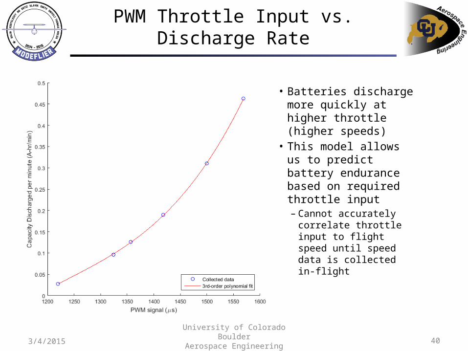
Battery Life Characterization
PWM (μs)Capacity Discharge
rate (A-hr/min)Approximate Battery
Life (min)
1220 0.0276 110
1324 0.0960 32
1357 0.1261 24.5
1418 0.1900 16
1500 0.3101 9.5
1569 0.4629 6.5
403/4/2015University of Colorado Boulder
Aerospace Engineering Sciences
PWM Throttle Input vs. Discharge Rate
• Batteries discharge more quickly at higher throttle (higher speeds)
• This model allows us to predict battery endurance based on required throttle input– Cannot accurately
correlate throttle input to flight speed until speed data is collected in-flight

413/4/2015University of Colorado Boulder
Aerospace Engineering Sciences
Battery Duration
• End-of-life defined as approximately 3.1Ahr discharged– LiPo manufactures
recommend never to discharge more than 80% of total capacity to preserve battery longevity
• RC flight test data will correlate throttle input to flight speed, and battery life can be estimated based on the necessary throttle input

423/4/2015University of Colorado Boulder
Aerospace Engineering Sciences
Ground Station Power Test
• Purpose: Verify ground station has power for full two hour test (DR2.2)
• Test: Connected all externally powered ground station modules to power supply and tested longevity
• Results: Power supplied for 230 minutes
Power supply
Mission PlannerData Displays
Ground station with mobile power supply

433/4/2015University of Colorado Boulder
Aerospace Engineering Sciences
SUV Cargo Test
• Procedure:– Gather all ground station,
aircraft, and flight testing components
– Position components within an SUV with cargo dimensions 1.5x1x0.9 m • If a larger SUV is used, the
proper dimensions will be marked with tape
– Photograph configuration that fits within the allotted space
• Purpose:– Verifies DR1.7 and DR2.5: The
aircraft and ground station can be transported in a cargo volume of 1.5x1x0.9 m
1m
1.5m

443/4/2015University of Colorado Boulder
Aerospace Engineering Sciences
Ground Dry Run – Electronic Endurance
• Procedure:– Connect and power all ground station components– Start a timer once all units are turned on– Proceed to complete remaining ground dry run tasks– Continue use of ground station until timer reaches 110
minutes
• Purpose:– Necessary to verify DR1.5: The demonstrations shall be
performed within 110 minutes• Verifies the ground station can provide power for allotted
time
– Allows for flight tests to conclude before 110 minutes which reduces the amount of time a pilot is needed

453/4/2015University of Colorado Boulder
Aerospace Engineering Sciences
Ground Dry Run – Proper Channel Communication
• Procedure:– Connect and power all avionics units (no motor)– Use RC transmitter to verify the servos are connected
to the right Pixhawk ports– Hold aircraft in a user safe position– Connect motor– Tap throttle to confirm motor responds correctly– Wait for propeller to stop moving, disconnect motor
from power
• Purpose:– Verifies the proper avionics connections are made– Also verifies that there are no faulty solder joints

463/4/2015University of Colorado Boulder
Aerospace Engineering Sciences
Ground Dry Run – Taking Data
• Procedure:– Connect and power all avionics units (no motor)– Allow Pixhawk to gather data with all electronic
systems working– Download data onto computer for analysis
following ground dry run
• Purpose:– Verify DR2.1: Meet the required aircraft state
variable measurement accuracy

473/4/2015University of Colorado Boulder
Aerospace Engineering Sciences
Ground Dry Run – Transmitting and Displaying Data
• Procedure:– Connect and power all avionics units (no motor) and ground
station components– Establish communication between ground station and aircraft– Carry aircraft to maximum flight distance from ground station– Allow Pixhawk to collect and transmit aircraft state variable
data to ground station– Use plotting script to display data on external monitors in real
time
• Purpose:– Verify DR2.1, DR2.2, DR2.3: Transmit data in real time, plot
data at 10 Hz rate, and data display must be observable by 10 people

483/4/2015University of Colorado Boulder
Aerospace Engineering Sciences
Ground Dry Run – Range Test
• Ground Dry Run – Range• Procedure:
– Connect and power all avionics units (no motor) – Establish communication between ground station and
aircraft– Carry aircraft to maximum COA distance from ground
station (note: this is a larger distance than the maximum flight distance)
– Command surface deflections with RC transmitter– Command surface deflections with ground station functions
• Purpose:– Verifies the communications system has sufficient range
capabilities– Reduces likelihood of lost link risk

493/4/2015University of Colorado Boulder
Aerospace Engineering Sciences
Ground Dry Run – Lost Link Protocol
• Procedure:– Connect and power all avionics units (no motor)– Establish communication between ground station and
aircraft– Verify connection with surface deflection commanded by
ground station– Disconnect communication system from aircraft avionics
suite– Observe surface deflections as per predefined lost link
commands
• Purpose:– Verifies that the lost link protocol has been properly
implemented– Reduces likelihood of the aircraft taking an unsafe flight
path in the event of lost communications and severity of losing communications

503/4/2015University of Colorado Boulder
Aerospace Engineering Sciences
Ground Dry Run – RC Override
• Procedure:– Connect and power all avionics components (no motor)– Establish communication between ground station and
aircraft– Command surface deflections with ground station
commands– Use RC transmitter to command a different deflection – Observe which surface deflection is performed
• Purpose:– Verifies DR3.3: Pilot shall be able to take full control of
aircraft at any time– Reduces severity of aircraft entering an undesirable
attitude

513/4/2015University of Colorado Boulder
Aerospace Engineering Sciences
Ground Dry Run – Video/LED Sync
• Procedure:– Connect and power all avionics components (no motor)– Establish communication between ground station and
aircraft– Ensure video camera is recording data– Command a function from ground station that drives the LED– Save data set from Pixhawk and video from camera– On computer, match function command time to LED light in
video
• Purpose:– Verifies DR4.2: Specific times in video can be correlated to the
correct data• Verifies the LED is visible in daylight• Proves that the sync procedure works

523/4/2015University of Colorado Boulder
Aerospace Engineering Sciences
Ground Dry Run – Battery Swap Time
• Procedure:– Connect all avionics units– Have team member walk aircraft to simulate a landing in the proper
location– Start timer– Have an additional team member, originally stationed at ground station,
gather and return the aircraft– Open fuselage compartment, disconnect battery pack and replace with a
new battery pack– Walk aircraft to takeoff location– Stop timer
• Purpose:– Necessary to verify DR1.5: The demonstrations shall be performed
within 110 minutes• Provides time necessary to swap out battery (i.e. the time between flights)
which allows the total time of multiple flights to be determined with only one flight
533/4/2015University of Colorado Boulder
Aerospace Engineering Sciences
Backup Slides: Requirements Satisfaction

University of Colorado Boulder Aerospace Engineering Sciences
54
FR1: A fixed-wing, conventional aircraft will individually demonstrate the phugoid, Dutch roll, and spiral modes in a manner visible to a ground observer.
Requirement ID
Description Verified by Test
DR1.1
The roll, pitch, and yaw angles of the aircraft will be distinguishable to a ground observer with 20/30 vision at a resolution of 5°. This defines the maximum range of demonstration as 200L for phugoid and spiral modes and 200b for Dutch roll mode, where L is the length of the aircraft from tip to tail and b is the wingspan of the aircraft.
Flight test
DR1.2The aircraft shall exhibit a phugoid mode with a pitch oscillation amplitude of at least 5 degrees, meeting minimum visibility requirement.
Flight Test
DR1.3The aircraft shall exhibit a Dutch roll mode with a roll oscillation amplitude of at least 5 degrees, meeting minimum visibility requirement.
Flight Test
DR1.4The aircraft shall exhibit a spiral mode with a yaw rotation of at least 180 degrees, or it shall reach a roll angle that approaches an unrecoverable attitude, within a safety factor. The roll angle that is defined as unrecoverable will be determined through simulations.
Flight Test
3/4/2015
Design Requirements from FR1

University of Colorado Boulder Aerospace Engineering Sciences
553/4/2015
Design Requirements from FR1
FR1: A fixed-wing, conventional aircraft will individually demonstrate the phugoid, Dutch roll, and spiral modes in a manner visible to a ground observer.
Requirement ID
Description Verified by Test
DR1.5The aircraft will be able to repeat the demonstration of all three modes in a period of 110 minutes (the duration of an ASEN 3128 lab) to at least 40 observers such that each observer has the opportunity to view the ground station display at least 1 time.
Ground station endurance test,
Battery change-out, Flight Tests
DR1.6 The aircraft shall not exceed a reproducibility cost of $1,000. N/A – Finances
DR1.7The aircraft shall be stored in a container to be placed in an SUV with a cargo space no greater than 150 cm x 100 cm x 90 cm.
SUV transport test

University of Colorado Boulder Aerospace Engineering Sciences
563/4/2015
Design Requirements from FR2
FR2: A ground station shall communicate with aircraft at all times and display live flight data of the aircraft state variables.
Requirement ID
Description Verified by Test
DR2.1
The aircraft will measure and transmit flight data of its aircraft state in real-time throughout its entire flight. The aircraft state measurements will abide to the following resolutions: 1 m for position components, 1 m/s for velocity components, 1° for Euler angles, and 1°/s for the angular rate components.
Sensor component test
DR2.2The ground station will process and output data of the aircraft state at a rate of at least 10 Hz.
Data display component test
DR2.3The ground station will produce a real-time, on-screen display of the aircraft state data that will be visible to at least 10 observers on the ground.
Data display component test

University of Colorado Boulder Aerospace Engineering Sciences
573/4/2015
Design Requirements from FR2
FR2: A ground station shall communicate with aircraft at all times and display live flight data of the aircraft state variables.
Requirement ID
Description Verified by Test
DR2.4 The ground station shall not exceed a reproducibility cost of $2,000. N/A – Finances
DR2.5The ground station must be stored in a conventional SUV with a cargo space no greater than 150 cm x 100 cm x 90 cm.
SUV transport test

University of Colorado Boulder Aerospace Engineering Sciences
583/4/2015
Design Requirements from FR3
FR3: The aircraft will function autonomously, and commands from the ground station will trigger mode demonstrations and allow for a pilot to directly operate the aircraft via RC in the case of an anomaly.
Requirement ID
Description Verified by Test
DR3.1The autopilot will allow the aircraft to fly in steady, level flight on a predetermined path until it is commanded otherwise.
Flight Tests
DR3.2The autopilot will return the aircraft to steady, level flight after the demonstration of each mode.
Flight Tests
DR3.3At any time during the flight, the RC pilot will be able to override the autopilot and give the pilot direct control of the aircraft in case of an anomaly.
RC override test

University of Colorado Boulder Aerospace Engineering Sciences
593/4/2015
Design Requirements from FR4
FR4: An onboard camera will capture video of the flight of the aircraft.Requirement
IDDescription Verified by Test
DR4.1 The video will be stored onboard and downlinked after aircraft has landed.Video camera
component test
DR4.2The video will be able to be correlated with the mode demonstrations such that the recorded flight data can be matched to specific times in the video.
Video/LED sync test

University of Colorado Boulder Aerospace Engineering Sciences
603/4/2015
Design Requirements from FR5
FR5: The aircraft shall be capable of takeoff and landing without requiring modifications to the flight environment and without suffering any damage that will impair operational capabilities.
Requirement ID
Description Verified by Test
DR5.1
The launch method will be appropriate for the test environment. The three methods being considered are hand-launched, bungee-launched, and ground take-off with landing gear. This will be highly dependent on the selected airframe.
Flight test
DR5.2The landing method will also be appropriate for the test environment. Methods considered will include landing gear and controlled belly-landing. This will be highly dependent on the selected airframe.
Landing simulation tests,
Flight test

613/4/2015University of Colorado Boulder
Aerospace Engineering Sciences
Level of Success 1
Success Requirement Validated ByAutonomous mode demonstrations commanded by ground station
Flight Test
2 of 3 modes demonstrated Flight Test
Record flight data Sensor Component Test

623/4/2015University of Colorado Boulder
Aerospace Engineering Sciences
Level of Success 2
Success Requirement Validated ByAll 3 modes demonstrated Flight Tests
Live data downlink and display
Data Display Component Test
Record flight videoVideo Component and Video/LED Sync Tests
Perform demonstrations in 110 minutes (1 lab period)
Ground station endurance test, Battery change-out,
Flight Tests
10 students can view ground station
Data Display Component Test
633/4/2015University of Colorado Boulder
Aerospace Engineering Sciences
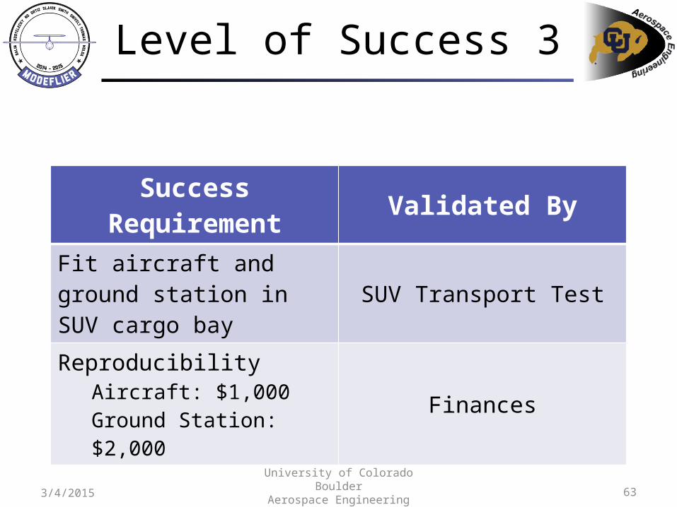
Level of Success 3
Success Requirement Validated ByFit aircraft and ground station in SUV cargo bay
SUV Transport Test
ReproducibilityAircraft: $1,000Ground Station: $2,000
Finances

643/4/2015University of Colorado Boulder
Aerospace Engineering Sciences
Backup Slides: Budget

65
Budget & SummaryGround Testing Flight TestingScheduleOverview
Purchases Breakdown
Category Total
Aircraft $939.88
Ground Station $1265.61
Miscellaneous $965.00
Testing $109.78
Total $3280.27
3/4/2015University of Colorado Boulder
Aerospace Engineering Sciences

66
Budget & SummaryGround Testing Flight TestingScheduleOverview
Aircraft Breakdown
Major Component Total
Techpod $186.70
Battery $36.29
Servos $90.95
Pixhawk $383.90
Propulsion System $84.17
Camera $39.69
Small Components $118.18
Total $939.88
3/4/2015University of Colorado Boulder
Aerospace Engineering Sciences

67
Budget & SummaryGround Testing Flight TestingScheduleOverview
Ground Station Breakdown
Component Total
Monitors $395.16
Monitor Splitter $149.99
Power Supplies $324.23
RC Controller $319.99
3DR Radio $51.25
Cable $24.99
Total $1265.61
3/4/2015University of Colorado Boulder
Aerospace Engineering Sciences

68
Budget & SummaryGround Testing Flight TestingScheduleOverview
Miscellaneous Breakdown
Item Total
FFR Printing $154.92
Extra Batteries $181.47
Extra Techpod $186.70
NexSTAR $144.99
NexSTAR Servos $73.96
Manufacturing Needs $37.55
Observer Medical Exam $150.00
Other Items $35.41
Total $965.00
3/4/2015University of Colorado Boulder
Aerospace Engineering Sciences

69
Budget & SummaryGround Testing Flight TestingScheduleOverview
Test Breakdown
Category Total
Servo Protractor $17.99
Extra Propellers $13.46
Static Thrust Stand $78.33
Total $109.78
3/4/2015University of Colorado Boulder
Aerospace Engineering Sciences


