Rhapsody 25e ARF - Horizon Hobby · Weight w/o Battery:Flying Your Rhapsody 25e ARF 3.70–3.90 oz...
24
Rhapsody 25e ARF Assembly Manual
Transcript of Rhapsody 25e ARF - Horizon Hobby · Weight w/o Battery:Flying Your Rhapsody 25e ARF 3.70–3.90 oz...

Rhapsody 25e ARFAssembly Manual

2 E-flite Rhapsody 25e ARF Assembly Manual
Notice
All instructions, warranties and other collateral documents are subject to change at the sole
discretion of Horizon Hobby, Inc. For up-to-date product literature, visit http://www.horizonhobby.com and click on the support tab for this product.
Meaning of Special Language
The following terms are used throughout the product literature to indicate various levels of potential harm
when operating this product:
NOTICE: Procedures, which if not properly followed, create a possibility of physical property damage
AND a little or no possibility of injury.
CAUTION: Procedures, which if not properly followed, create the probability of physical property damage
AND a possibility of serious injury.
WARNING: Procedures, which if not properly followed, create the probability of property damage, collateral
damage, and serious injury OR create a high probability of superficial injury.
WARNING: Read the ENTIRE instruction manual to become familiar with the features of the product before operating. Failure to operate the product correctly can result in damage to the product, personal property and cause serious injury.
This is a sophisticated hobby product and NOT a toy. It must be operated with caution and common sense and requires some basic mechanical ability. Failure to operate this Product in a safe and responsible manner could result in injury or damage to the product or other property. This product is not intended for use by children without direct adult supervision. Do not attempt disassembly, use with incompatible components or augment product in any way without the approval of Horizon Hobby, Inc. This manual contains instructions for safety, operation and maintenance. It is essential to read and follow all the instructions and warnings in the manual, prior to assembly, setup or use, in order to operate correctly and avoid damage or serious injury.
Introduction
The Rhapsody 25e combines modern styling with classic lines to give you a one-of-a-kind sport biplane that’s a real standout. On the ramp, its striking Ultracote® trim scheme, along with the factory-painted fiberglass cowl and wheel pants, will turn more than a few heads. In the air, its crisp roll rates and smooth, predictable flight characteristics will let you enjoy a wide range of sport aerobatics without any surprises. Best of all, you can have the Rhapsody 25e flying in just an evening or two thanks to handy features like the bolt-on tail and included wing jigs that make assembly a breeze.
Important Information Regarding Warranty Information
Please read our Warranty and Liability Limitations section on Page 21 before building this product. If you as the Purchaser or user are not prepared to accept the liability associated with the use of this Product, you are advised to return this Product immediately in new and unused condition to the place of purchase.
SpecificationsWingspan: 47.0 in (1190mm)Length: 39.0 in (990mm)Wing Area: 530 sq in (34.0 sq dm)Weight with Battery: 4.40–4.60 oz (1.90–2.10 kg)Weight w/o Battery: 3.70–3.90 oz (1.60–1.80 kg)
Using the Manual
This manual is divided into sections to help make assembly easier to understand, and to provide breaks between each major section. In addition, check boxes have been placed next to each step to keep track of its completion. Steps with a single circle () are performed once, while steps with two circles ( ) indicate the step will require repeating, such as for a right or left wing panel, two servos, etc.
Remember to take your time and follow the directions.
Table of ContentsNotice ................................................................... 2Meaning of Special Language ................................. 2Introduction ........................................................... 2Important Information Regarding
Warranty Information ........................................ 2Specifications ......................................................... 2Using the Manual ................................................... 2Contents of Kit/Parts Layout .................................... 3Covering Colors ..................................................... 3Hardware/Accessory Sizes ..................................... 3Recommended Radio Equipment ............................. 3Power 25 Motor Setup ........................................... 3Power 32 Motor Setup ........................................... 3Required Tools and Adhesives ................................. 3Optional Accessories .............................................. 3Warnings .............................................................. 4Rudder and Stabilizer Installation ............................ 4Landing Gear Installation ........................................ 5Motor, Speed Control and Cowling Installation ......... 7Aileron Servo Installation ........................................ 9Rudder and Elevator Servo Installation ................... 11Bottom Wing and Receiver Installation ................... 13Top Wing Installation ............................................ 14Removing the Wing Panels ................................... 17Motor Battery, Propeller and Pilot Installation ......... 17Center of Gravity ................................................. 18Control Throws..................................................... 19Preflight ............................................................... 19Flying Your Rhapsody 25e ARF ............................. 20Range Test Your Radio .......................................... 20Safety Do’s and Don’ts for Pilots ............................ 20Daily Flight Checks ............................................... 20Warranty and Repair Policy .................................. 21Warranty Services ................................................ 21Compliance Information for the European Union .... 222010 Official Academy of
Model Aeronautics Safety Code ....................... 22

3E-flite Rhapsody 25e ARF Assembly Manual
Contents of Kit/Parts LayoutReplacement Parts
EFL4176001 Bottom Wing SetEFL4175002 Top Wing SetEFL4175003 Fuselage with HatchEFL4175004 Tail SetEFL4175005 Wing Strut SetEFL4175006 CowlingEFL4175007 Wing Truss SetEFL4175008 Wheel Pant SetEFL4175009 Decal SetEFL4175010 Pushrod SetEFL4175011 Main GearEFL4175012 Wing Spar SetEFL4175013 Wing Cabane SetEFL4175015 Hardware Set
Covering ColorsWhite HANU870Deep Blue HANU873Gold HANU879
Hardware/Accessory SizesMain wheel diameter 2.5-inch (63.0mm)Tail wheel diameter 1-inch (25.0mm)Bottom wing bolt 6-32 x 1-inch
socket head boltTop/bottom wing retention bolt 4-40 x 1/2-inch
socket head bolt
Recommended Radio Equipment
You will need a minimum 4-channel transmitter, receiver and four servos. You can choose to purchase a complete radio system. If you are using an existing transmitter, just purchase the other required equipment separately. We recommend the crystal-free, interference-free Spektrum™ DX6i 2.4GHz DSM® 6-channel system. If using your own transmitter, we recommend the following radio equipment.
If you own the Spektrum DX6i radio, or you are using a different DSM2 radio, just add the AR6200 DSM2™ 6-channel receiver and four JR SPORT™ MN48 servos.Complete Radio System
SPM6600 DX6i DSM2 6CH systemOr Purchase Separately
SPMAR6200 AR6200 DSM2 6-Channel Full-Range Receiver (for DX6i or DX7)
JSP20040 MN48 Servo (4)EFLRYH3 3-inch Y-Harness, Lightweight
Power 25 Motor SetupEFLM4025A Power 25 Brushless Outrunner
Motor, 870KvEFLA1040 40-Amp Pro Switch-Mode
BEC Brushless ESCAPC12080E APC 12 x 8 Electric PropellerEFLB32003S30 3200mAh 3S 11.1V 30C LiPo,
12AWG EC3
Power 32 Motor SetupEFLM4032A Power 32 Brushless Outrunner
Motor, 770KvEFLA1060 60-Amp Pro Switch-Mode
BEC Brushless ESCAPC13065E APC 13 x 6.5 Electric PropellerEFLB32004S30 3200mAh 4S 14.8V 30C LiPo,
12AWG EC3
Required Tools and AdhesivesTools & Equipment
Flat file Pin viseSide cutter ScissorsCovering Iron RulerNut driver: 1/4-inchPhillips screwdriver: #1, #2Drill bit: 5/64-inch (2mm)Hobby knife with #11 bladeHex wrench: 1.5mm, 3/32-inch, 7/64-inchOpen end or box wrench: 1/2-inch, 12mm
AdhesivesThreadlock Thin CAMedium CA
Optional AccessoriesEFLA110 Power MeterEFLC505 Intelligent 1- to 5-Cell
Balancing ChargerEFLAEC312 Charge Lead with 12-inch
Wire and Jacks, 16AWGEFLA151 Civilian Pilot, BlueEFL4539 Dummy Motor
The Spektrum trademark is used with permission of Bachmann Industries, Inc.
All other marks are trademarks or registered trademarks of Horizon Hobby, Inc.

4 E-flite Rhapsody 25e ARF Assembly Manual
Warnings
Read and follow all instructions and safety precautions before use. Improper use can result in fire, serious injury and damage to property.
COMPONENTS
Use only with compatible components. Should any compatibility questions exist please refer to the product instructions, the component instructions or contact Horizon Hobby, Inc.
FLIGHT
Fly only in open areas to ensure safety. It is recommended flying be done at AMA (Academy of Model Aeronautics) approved flying sites. Consult local laws and ordinances before choosing a location to fly your aircraft.
PROPELLER
Keep loose items that can get entangled in the propeller away from the prop, including loose clothing, or other objects such as pencils and screwdrivers. Especially keep your hands away from the propeller as injury can occur.
BATTERIES
Notes on Lithium Polymer Batteries
When misused, lithium polymer batteries are significantly more volatile than alkaline or Ni-Cd/Ni-MH batteries used in RC applications. Always follow the manufacturer’s instructions when using and disposing of any batteries. Mishandling of Li-Po batteries can result in fire and explosion causing serious injury and damage.
SMALL PARTS
This kit includes small parts and should not be left unattended near children as choking and serious injury could result.
SAFETy PRECAUTIONS
This is a sophisticated hobby Product and not a toy. It must be operated with caution and common sense and requires some basic mechanical ability. Failure to operate this Product in a safe and responsible manner could result in injury or damage to the Product or other property. This Product is not intended for use by children without direct adult supervision. The Product manual contains instructions for safety, operation and maintenance. It is essential to read and follow all the instructions and warnings in the manual, prior to assembly, setup or use, in order to operate correctly and avoid damage or injury.
During the course of building your Rhapsody 25e we suggest you use a soft base for the building surface. Such things as a foam stand, large piece of bedding foam or a thick bath towel will work well and help protect the model from damage during assembly.
Rudder and Stabilizer InstallationRequired Parts
Stabilizer assembly Fuselage assemblyFin assembly 4-40 locknut (2)#4 washer (4)4-40 x 1/2-inch machine screw (2)
Required Tools and AdhesivesThreadlock Nut driver: 1/4-inchThin CA Phillips screwdriver: #1
Make sure to use threadlock on all metal-to-metal fasteners so they don’t vibrate loose.
1. Locate the stabilizer and fin assemblies. Insert the threaded rods on the bottom of the fin into the holes in the stabilizer. Note the trim scheme of the stabilizer in the photos.
5E-flite Rhapsody 25e ARF Assembly Manual
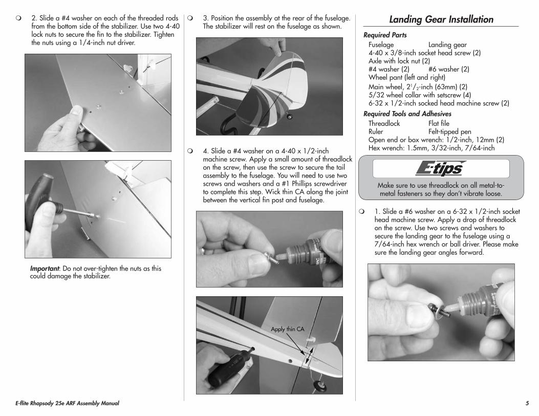
2. Slide a #4 washer on each of the threaded rods from the bottom side of the stabilizer. Use two 4-40 lock nuts to secure the fin to the stabilizer. Tighten the nuts using a 1/4-inch nut driver.
Important: Do not over-tighten the nuts as this could damage the stabilizer.
3. Position the assembly at the rear of the fuselage. The stabilizer will rest on the fuselage as shown.
4. Slide a #4 washer on a 4-40 x 1/2-inch machine screw. Apply a small amount of threadlock on the screw, then use the screw to secure the tail assembly to the fuselage. You will need to use two screws and washers and a #1 Phillips screwdriver to complete this step. Wick thin CA along the joint between the vertical fin post and fuselage.
Landing Gear InstallationRequired Parts
Fuselage Landing gear4-40 x 3/8-inch socket head screw (2)Axle with lock nut (2)#4 washer (2) #6 washer (2)Wheel pant (left and right)Main wheel, 21/2-inch (63mm) (2)5/32 wheel collar with setscrew (4)6-32 x 1/2-inch socked head machine screw (2)
Required Tools and AdhesivesThreadlock Flat fileRuler Felt-tipped penOpen end or box wrench: 1/2-inch, 12mm (2)Hex wrench: 1.5mm, 3/32-inch, 7/64-inch
Make sure to use threadlock on all metal-to-metal fasteners so they don’t vibrate loose.
1. Slide a #6 washer on a 6-32 x 1/2-inch socket head machine screw. Apply a drop of threadlock on the screw. Use two screws and washers to secure the landing gear to the fuselage using a 7/64-inch hex wrench or ball driver. Please make sure the landing gear angles forward.

6 E-flite Rhapsody 25e ARF Assembly Manual
2. Use open end or box wrenches to secure the landing gear axle to the landing gear. You will need 1/2-inch and 12mm wrenches to tighten the axle to the gear.
3. Use a flat file to make two 1/4-inch (6mm) wide flat areas on the axle for the setscrews in the wheel collars. Position the flats 1/4-inch (6mm) and 11/8-inch (28mm) from the outer end of the axle as shown.
4. Slide a 5/32-inch wheel collar on the axle and use a 1.5mm hex wrench to tighten the setscrew on the flat made in the previous step. Slide the wheel in position and use a second wheel collar and 1.5mm hex wrench to secure the wheel on the axle. Check that the wheel can rotate freely on the axle. If not, reposition the wheel collars so they are not binding against the wheel. Make sure to use threadlock on the setscrews so they don’t vibrate loose.
5. Slide a #4 washer on a 4-40 x 3/8-inch socket head machine screw. Apply a drop of threadlock to the screw. Use the screw to attach the wheel pant to the landing gear as shown. Use a 3/32-inch hex wrench to tighten the screw.
6. Repeat Steps 2 through 5 to install the remaining wheel to the landing gear.

7E-flite Rhapsody 25e ARF Assembly Manual
Motor, Speed Control and Cowling Installation
Required PartsFuselage assemblyCowling4-40 x 3/8-inch socket head machine screw (4)#4 washer (4)Hook and loop tapeHook and loop strap (2)
Required Parts (Power 25)Power 25 brushless outrunnerX-mount with screwsElectronic speed control, 40-amp4-40 x 3/8-inch socket head screw (4)#4 washer (4)
Required Parts (Power 32)Power 32 brushless outrunnerX-mount with screwsElectronic speed control, 60-amp4-40 x 3/4-inch socket head screw (4)#4 washer (4)Aluminum spacer, 1/4-inch (6mm) (4)
Required Tools and AdhesivesHex wrench or ball driver: 3/32-inchPhillips screwdriver: #1, #2Threadlock
Optional PartsDummy motor (EFL4539)
Paint Colors for Dummy RadialAluminumBlackYellowLight Gray
1. Remove the hatch cover from the top of the fuselage by lifting the rear of the hatch. The front is held in place using two dowels.
Make sure to use threadlock on all metal-to-metal fasteners so they don’t vibrate loose.
2. Use the screws included with the motor to attach the X-mount to the rear of the motor.
The blind nuts in the firewall for the motor can be repositioned for a variety of motor
installations. You will need to adjust their position to suit your particular motor selection.
Make sure to use threadlock on all metal-to-metal fasteners so they don’t vibrate loose.
3A. Attach the Power 25 motor to the firewall using four 4-40 by 3/8-inch socket head machine screws and four #4 washers. Use a 3/32-inch hex wrench to tighten the screws.
3B. Attach the Power 32 motor to the firewall using four 4-40 by 3/4-inch socket head machine screws and four #4 washers. Place the four 1/4-inch (6mm) aluminum spacers between the mount and firewall as shown. Use a 3/32-inch hex wrench to tighten the screws.
8 E-flite Rhapsody 25e ARF Assembly Manual
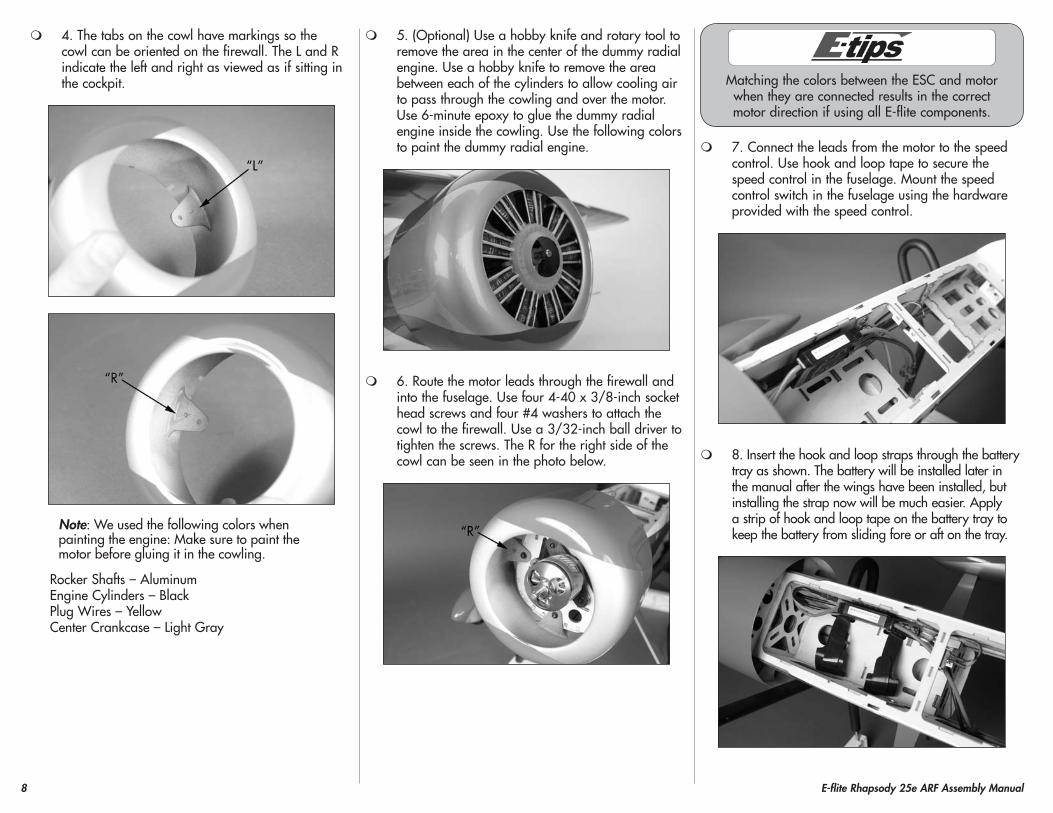
4. The tabs on the cowl have markings so the cowl can be oriented on the firewall. The L and R indicate the left and right as viewed as if sitting in the cockpit.
Note: We used the following colors when painting the engine: Make sure to paint the motor before gluing it in the cowling.
Rocker Shafts – AluminumEngine Cylinders – BlackPlug Wires – YellowCenter Crankcase – Light Gray
5. (Optional) Use a hobby knife and rotary tool to remove the area in the center of the dummy radial engine. Use a hobby knife to remove the area between each of the cylinders to allow cooling air to pass through the cowling and over the motor. Use 6-minute epoxy to glue the dummy radial engine inside the cowling. Use the following colors to paint the dummy radial engine.
6. Route the motor leads through the firewall and into the fuselage. Use four 4-40 x 3/8-inch socket head screws and four #4 washers to attach the cowl to the firewall. Use a 3/32-inch ball driver to tighten the screws. The R for the right side of the cowl can be seen in the photo below.
Matching the colors between the ESC and motor when they are connected results in the correct motor direction if using all E-flite components.
7. Connect the leads from the motor to the speed control. Use hook and loop tape to secure the speed control in the fuselage. Mount the speed control switch in the fuselage using the hardware provided with the speed control.
8. Insert the hook and loop straps through the battery tray as shown. The battery will be installed later in the manual after the wings have been installed, but installing the strap now will be much easier. Apply a strip of hook and loop tape on the battery tray to keep the battery from sliding fore or aft on the tray.

9E-flite Rhapsody 25e ARF Assembly Manual
Aileron Servo InstallationRequired Parts
Bottom wing panel (right and left)Servo with hardware2mm x 10mm sheet metal screw (8)Nylon clevis (2) Silicone clevis retainer (2)2-56 x 17/8-inch pushrod (2)Transmitter ReceiverReceiver battery
Required Tools and AdhesivesThin CA Phillips screwdriver: #1Pin vise Drill bit: 5/64-inch (2mm)Side cutter Covering iron
1. Remove the servo cover from the wing. You may need to use a covering iron to reseal the covering to the wing if the tape lifts the covering.
2. Prepare the aileron servo by installing the servo grommets and brass eyelets. Remove the servo horn from the servo using a #1 Phillips screwdriver.
3. Apply 2–3 drops of thin CA in each of the servo mounting holes to harden the surrounding wood. This will help in preventing the screws from vibrating loose.
4. Secure the aileron servo to the servo mount using the hardware included with the servo. Use a #1 Phillips screwdriver to tighten the screws. Note that the output for the servo is centered in the slot where the servo arm will protrude through the cover.
5. Use a pin vise and 5/64-inch (2mm) drill bit to enlarge the hole in the servo horn. Enlarge the inner hole of the longer arm of a standard servo arm. This hole is 3/8-inch (10mm) from the center of the horn as shown. Use side cutters to remove any unused arms so they don’t interfere with the operation of the servo.

10 E-flite Rhapsody 25e ARF Assembly Manual
6. Use the radio system to center the aileron servo. Use the screw from the servo to install the servo horn on the servo as shown. Use a #1 Phillips screwdriver to tighten the screw that secures the servo horn to the servo output.
7. A string is located in the wing to pull the servo lead through the wing. Tie the string to the end of the servo lead as shown.
8. Apply 2–3 drops of thin CA in each of the servo cover mounting holes to harden the surrounding wood. This will help in preventing the screws from vibrating loose.
9. Install the servo and cover using four 2mm x 10mm sheet metal screws and a #1 Phillips screwdriver. Carefully pull the servo lead through the wing at this time. Leave the string tied to the servo lead.
10. Attach the 2-56 x 17/8-inch pushrod wire to the servo horn using the bend in the wire. Slide a silicone clevis keeper on a clevis. Thread the clevis on the pushrod wire. With the servo centered, connect the clevis to the outer hole on the control horn. Make sure the aileron is centered when the clevis is connected. Slide the silicone clevis keeper over the forks of the clevis to keep it from opening accidentally in flight.
Drawing not to scale
Attach clevisto outer hole
11. Repeat Steps 1 though 10 to install the remaining aileron servo.

11E-flite Rhapsody 25e ARF Assembly Manual
Rudder and Elevator Servo InstallationRequired Parts
Fuselage assembly Nylon clevis (2)Transmitter ReceiverReceiver batteryServo with hardware (2)Silicone clevis retainer (2)Pushrod wire, 2-56 x 191/2-inch (rudder)Pushrod wire, 2-56 x 183/4-inch (elevator)
Required Tools and AdhesivesPin vise Drill bit: 5/64-inch (2mm)Thin CA Phillips screwdriver: #1Side cutter Ruler
1. Apply 2–3 drops of thin CA in each of the servo mounting holes to harden the surrounding wood. This will help in preventing the screws from vibrating loose.
2. Prepare the rudder and elevator servos by installing the servo grommets and brass eyelets. Remove the servo horn from the servo as well.
3. Secure the elevator and rudder servos in the radio tray using the hardware included with the servo. Use a #1 Phillips screwdriver to tighten the screws. Note that the output for the servos face to the front of the fuselage.
4. Use a pin vise and 5/64-inch (2mm) drill bit to enlarge the hole in the servo horn. Use side cutters to remove any unused arms so they don’t interfere with the operation of the servo.
5. Attach the 2-56 x 183/4-inch elevator pushrod wire to the servo horn using the bend in the wire.

12 E-flite Rhapsody 25e ARF Assembly Manual
6. Slide the pushrod wire into the pushrod tube inside the fuselage. Center the elevator servo using the radio system. Attach the servo horn to the servo output using the hardware provided with the servo and a #1 Phillips screwdriver.
7. Repeat Steps 4 though 6 to install the rudder servo horn and the 2-56 x 191/2-inch rudder pushrod wire.
When centering the control surfaces, use a ruler or straightedge to make sure the surface is in alignment.
8. Slide a silicone clevis keeper on a clevis. Thread the clevis on the pushrod wire. With the servo centered, connect the clevis to the outer hole on the control horn. Make sure the elevator is centered when the clevis is connected. Slide the silicone clevis keeper over the forks of the clevis to keep it from opening accidentally in flight.
Drawing not to scale
Attach clevisto outer hole
9. Slide a silicone clevis keeper on a clevis. Thread the clevis on the pushrod wire. With the servo centered, connect the clevis to the outer hole on the control horn. Make sure the rudder is centered when the clevis is connected. Slide the silicone clevis keeper over the forks of the clevis to keep it from opening accidentally in flight.
Drawing not to scale
Attach clevisto outer hole

13E-flite Rhapsody 25e ARF Assembly Manual
Bottom Wing and Receiver InstallationRequired Parts
Fuselage assembly Y-harness Receiver #4 washer (2)#6 washer (2) Bottom wing center sectionHook and loop tapeCarbon wing tube, shortBottom wing panel (right and left)6-32 x 1-inch socket head machine screw (2)4-40 x 1/2-inch socket head machine screw (2)
Required Tools and AdhesivesHex wrench: 3/32-inch, 7/64-inchScissors ThreadlockHobby knife with #11 blade
1. Use a hobby knife with a #11 blade to remove the covering from the top of the bottom center section for the aileron Y-harness.
2. Insert the Y-harness in the center section. Make sure the end that plugs into the receiver is exiting the hole in the top of the center section.
3. Use scissors to cut a piece of hook and loop tape the size of the receiver. Use the tape to secure the receiver to the center section as shown. Plug the Y-harness into the aileron port of the receiver.
4. Plug the rudder, elevator and speed control leads into the appropriate ports of the receiver at this time.
Make sure to use threadlock on all metal-to-metal fasteners so they don’t vibrate loose.
5. Attach the center section to the fuselage using two 6-32 x 1-inch socket head machine screws and two #6 washers. Use a 7/64-inch hex wrench to tighten the screws.

14 E-flite Rhapsody 25e ARF Assembly Manual
6. Use scissors to cut a piece of hook and loop tape the size of the remove receiver. Use the tape to attach the remote receiver to the side of the fuselage as shown.
7. Slide the short carbon wing tube in the bottom wing panel. The tube will slide in the socket easily, so don’t force it farther than it will easily slide.
We left the string tied to the aileron servo lead, but cut it to a length of 3-inches (76mm) so the lead can
be easily retrieved if it falls back into the wing.
8. Slide the carbon tube and wing panel into the bottom wing center section. Plug the lead from the aileron servo into the Y-harness. The panel will fit tight against the center section when installed.
9. Use a 4-40 x 1/2-inch socket head machine screw and #4 washer to secure the wing panel to the center section. Use a 3/32-inch hex wrench to tighten the screw.
10. Repeat Steps 8 and 9 to attach the remaining bottom wing panel.
Top Wing InstallationRequired Parts
Fuselage assembly #4 washer (22)Top wing panel (right and left)Top wing center sectionOuter strut fitting (8)Carbon wing tube, longCabane strut decal (4)Cabane strut, left (2)Cabane strut, right (2)Outer strut (right and left)Nylon clevis (4) Silicone clevis retainer (4)2-56 x 63/4-inch pushrod (2)4-40 x 1/4-inch socket head machine screw (8)4-40 x 3/8-inch socket head machine screw (4)4-40 x 1/2-inch socket head machine screw (10)
Required Tools and AdhesivesThreadlock Hex wrench: 3/32-inch
Make sure to use threadlock on all metal-to-metal fasteners so they don’t vibrate loose.
1. Use eight 4-40 x 1/2-inch socket head machine screws and eight #4 washers to attach the cabane struts to the fuselage. Note the left cabane struts are marked and are located on the left side of the fuselage as viewed if sitting in the pilot seat. Do not tighten the screws at this time as they will be tightened after the wings are installed on the aircraft.

15E-flite Rhapsody 25e ARF Assembly Manual
Make sure to use threadlock on all metal-to-metal fasteners so they don’t vibrate loose.
2. Thread the two outer strut fittings into the blind nuts installed in the top of the bottom wing panel. Install fittings in both the right and left wing panels at this time. Make sure the fitting is installed so the bottom is flush with the wing and they are facing parallel to each other as shown.
Make sure to use threadlock on all metal-to-metal fasteners so they don’t vibrate loose.
3. Attach the top wing center section to the cabane struts using four 4-40 x 3/8-inch socket head machine screws and four #4 washers. Use a 3/32-inch hex wrench to tighten the screws.
Make sure to use threadlock on all metal-to-metal fasteners so they don’t vibrate loose.
4. Thread the two outer strut fittings into the blind nuts installed in the bottom of the top wing panel. Install fittings in both the right and left wing panels at this time. Make sure the fitting is installed so the bottom is flush with the wing and they are facing parallel to each other as shown.
5. Slide the long carbon wing tube in the top wing panel. The tube will slide in the socket easily, so don’t force it farther than it will easily slide.
6. Slide the carbon tube and wing panel into the top wing center section. The panel will fit tight against the center section when installed.
7. Use a 4-40 x 1/2-inch socket head machine screw and #4 washer to secure the top wing panel to the top center section. Use a 3/32-inch hex wrench to tighten the screw.

16 E-flite Rhapsody 25e ARF Assembly Manual
8. Slide the remaining wing panel into position and secure it to the center section using a 4-40 x 1/2-inch socket head machine screw and #4 washer. Use a 3/32-inch hex wrench to tighten the screw.
9. Locate the outer strut. Note the bottom of the strut has more curvature than the top to fit the airfoil of the bottom wing.
10. Use four 4-40 x 1/4-inch socket head machine screws and four #4 washers to attach the outer strut to the strut fitting. Note that the inside of the mounting holes for the outer strut will fit over the fittings when installed and that the screws are installed from the wing tip as shown.
11. Tighten the screws that secure the cabane struts in the fuselage. Use a 3/32-inch hex wrench or ball driver to tighten the screws for this step.
12. Use the cabane strut decal to cover the holes where the cabane strut screws are located.
13. Slide a silicone clevis retainer on a clevis. Prepare two clevises, then thread them on the ends of the 2-56 x 63/4-inch pushrod. With the bottom aileron centered, adjust the length of the linkage so the top aileron is centered as well. Once the length is set, make sure both clevises are secure and that the silicone retainer has been slid over the forks of the clevis. Repeat for the opposite aileron connection.

17E-flite Rhapsody 25e ARF Assembly Manual
Removing the Wing PanelsRequired Parts
Assembled airframeWing transport truss (2)Rubber band (4)
Required Tools and AdhesivesHex wrench: 3/32-inch
Note: This section is to show you how to remove the wings using the transport trusses. The wings are reinstalled repeating the procedure starting from Step 3 and going to Step 1.
1. Locate the wing transport trusses and four rubber bands. Slide the braces between the top and bottom wing as shown. Use a rubber band to hold the truss to the top and bottom wing. Make sure the truss is positioned on the wing and not the center sections attached to the fuselage.
2. Use a 3/32-inch hex wrench to remove the 4-40 screws that attach the panels to the center section. Slide the panels from the tube and disconnect the servo lead for the aileron servo.
Using the transport brace allows the removal of the wing without the need to remove the aileron linkage
and the outer strut between the top and bottom wings.
3. Repeat Steps 1 and 2 to remove the remaining wing panels from the fuselage.
Note: To reattach the wings, simply step through Steps 1 through 3 in reverse order.
Motor Battery, Propeller and Pilot Installation
Required PartsFuselage assembly Canopy hatchPropeller TransmitterPropeller adapter Motor battery (charged)
Required Tools and AdhesivesMedium CA Hex wrench: 3/32-inch
Optional AccessoriesCivilian Pilot, Blue (EFLA151)
1. Use the hook and loop straps to secure the motor battery in the fuselage.

18 E-flite Rhapsody 25e ARF Assembly Manual
Always balance your propeller. An unbalanced propeller can cause vibrations to be transmitted
into the airframe, which could damage the airframe or other components as well as produce unwanted flight characteristics.
2. Use the propeller adapter to secure the propeller to the motor. Slide a 3/32-inch hex wrench through the hole in the adapter to tighten it, securing the propeller.
3. Connect the battery and speed control. Use the transmitter to check the operation of the motor. If connected as described earlier, the motor will spin counterclockwise when viewed from the front of the fuselage.
4. Use medium CA to glue the pilot in the cockpit as shown.
5. Place the canopy hatch on the top of the fuselage. The front of the hatch has pins that key into the front former, and magnets holding the rear of the hatch to the fuselage.
Do not remove the canopy hatch by lifting it up by the pilot. You may accidentally remove the pilot.
6. Apply the decals to your model using the photos on the box as a guide. Use a spray bottle filled with water and a drop of dish washing detergent sprayed on the airframe will allow easier repositioning of the decals. Squeegee the excess water from under the decal and allow them to set overnight before flying your model.
Center of Gravity
An important part of preparing the aircraft for flight is properly balancing the model.
Do not inadvertently skip this step or property damage and injury could occur.
The recommended Center of Gravity (CG) location for your model is 33/4 to 41/2 inches (95 to 114mm) back from the leading edge of the top wing as shown with the battery pack installed. Mark the location of the CG on the bottom of the top wing with a felt-tipped pen.
When balancing your model, support the plane upright at the marks made on the bottom of the top wing with your fingers or a commercially available balancing stand. This is the correct balance point for your model. Make sure your model is assembled and ready for flight before balancing.
Adjust the motor battery as necessary so the model is level or slightly nose down. This is the correct balance point for your model. You should find the CG to be very close with the battery installed as shown in this manual. Mark the location of the battery on the battery tray using a felt-tipped pen so it can be returned to this position if it is removed from your model.
After the first flights, the CG position can be adjusted for your personal preference.

19E-flite Rhapsody 25e ARF Assembly Manual
Control Throws
1. Turn on the transmitter and receiver of your model. Check the movement of the rudder using the transmitter. When the stick is moved right, the rudder should also move right. Reverse the direction of the servo at the transmitter if necessary.
2. Check the movement of the elevator with the radio system. Moving the elevator stick toward the bottom of the transmitter makes the airplane elevator move up.
3. Check the movement of the ailerons with the radio system. Moving the aileron stick right makes the right aileron move up and the left aileron move down.
4. Use a ruler to adjust the throw of the elevator, ailerons and rudder. Adjust the position of the pushrod at the control horn to achieve the following measurements when moving the sticks to their endpoints.
Elevator High Rate (100%)Up 1-inch (25mm)Down 1-inch (25mm)
Elevator Low RateUp 1/2-inch (13mm)Down 1/2-inch (13mm)
Aileron High Rate (100%)Up 5/8-inch (15mm)Down 5/8-inch (15mm)
Aileron Low RateUp 3/8-inch (9mm)Down 3/8-inch (9mm)
Rudder High Rate (100%)Right 2-inch (50mm)Left 2-inch (50mm)
Rudder Low RateRight 11/2-inch (38mm)Left 11/2-inch (38mm)
Measurements are taken at the inner or widest point on the control surface.
These are general guidelines measured from our own flight tests. You can experiment with higher rates to match your preferred style of flying.
Travel Adjust and Sub-Trims are not listed and should be adjusted according to each
individual model and preference.
PreflightCheck your Radio
Before going to the field, be sure your batteries are fully charged per the instructions included with your radio. Charge the transmitter and motor battery for your airplane. Use the recommended charger supplied with your particular radio system, following the instructions provided with the radio. In most cases, the radio should be charged the night before going out flying.
Before each flying session, be sure to range check your radio. See your radio manual for the recommended range and instructions for your radio system. Each radio manufacturer specifies different procedures for their radio systems. Next, run the motor. With the model securely anchored, check the range again. The range test should not be significantly affected. If it is, don’t attempt to fly! Have your radio equipment checked out by the manufacturer.
Double-check that all controls (aileron, elevator, rudder and throttle) move in the correct direction.
Check the radio installation and make sure all the control surfaces are moving correctly (i.e., the correct direction and with the recommended throws).
Check all the control horns, servo horns, and clevises to make sure they are secure and in good condition.

20 E-flite Rhapsody 25e ARF Assembly Manual
Flying your Rhapsody 25e ARF
As you taxi out to the runway you will find the ground handling to be very gentle and easy. The wide stance main gear and low angled stance keeps the model tracking very straight through all aspects on the ground. Once you are lined up on the runway ensure you have your throttle trim set to where the motor is spinning at a low idle setting. This is your flight idle. Apply power smoothly and steering with rudder. You will find the tail to come up very quickly and the model will accelerate straight ahead effortlessly. Once up to speed pull back slightly and ease the elevator control to establish a solid shallow climb to altitude. Once at altitude you will want to trim the model for level flight at about ¾ power. Once trimmed try some basic stalls to become comfortable with the model’s handling. You will find the model stalls very gently and forward routinely.
You will find the model is quite aerobatic and can perform loops, rolls, inverted flight, and all the other basic aerobatic maneuvers with ease. Landings are a thing of beauty as you glide in and settle gently to a 3-point touch down. The model also likes to be wheel landed, the choice is yours. We hope you enjoy your Rhapsody as much as we enjoy ours.
Happy Landings!
Range Test your Radio
Before each flying session, and especially with a new model, it is important to perform a range check. It is helpful to have another person available to assist during the range check. If you are using a Spektrum transmitter, please refer to your transmitter’s manual for detailed instructions on the range check process.
1. With the model resting on the ground, stand 30 paces (approximately 90 feet) away from the model.
2. Face the model with the transmitter in your normal flying position. Be sure the throttle is in the full down position and plug the flight battery into the speed control.
3. As you move the controls, watch to be sure the airplane’s motor and controls operate smoothly. You should have total control of the model at 30 paces (90 feet).
4. If control issues exist, call the appropriate Horizon Product Support office (see page 22) or go to horizonhobby.com to find a local Spektrum distributor in your country for service if using a Spektrum radio system.
Safety Do’s and Don’ts for Pilots
• Checkallcontrolsurfacespriortoeachtakeoff.
• Donotflyyourmodelnearspectators,parkingareas or any other area that could result in injury to people or damage of property.
• Donotflyduringadverseweatherconditions.Poorvisibility can cause disorientation and loss of control of your aircraft. Strong winds can cause similar problems.
• Donottakechances.Ifatanytimeduringflightyouobserve any erratic or abnormal operation, land immediately and do not resume flight until the cause of the problem has been ascertained and corrected. Safety can never be taken lightly.
• Donotflynearpowerlines.
Daily Flight Checks
1. Check the battery voltage of the transmitter battery. Do not fly below the manufacturer’s recommended voltage. To do so can crash your aircraft.
When you check these batteries, ensure you have the polarities correct on your expanded scale voltmeter.
2. Check all hardware (linkages, screws, nuts, and bolts) prior to each day’s flight. Be sure that binding does not occur and that all parts are properly secured.
3. Ensure all surfaces are moving in the proper manner.
4. Perform a ground range check before each day’s flying session.
5. Prior to starting your aircraft, turn off your transmitter, then turn it back on. Do this each time you start your aircraft. If any critical switches are on without your knowledge, the transmitter alarm will sound a warning at this time.
6. Check that all trim levers are in the proper location.
7. All servo pigtails and switch harness plugs should be secured in the receiver. Make sure the switch harness moves freely in both directions.

21E-flite Rhapsody 25e ARF Assembly Manual
Warranty and Repair Policy
WARRANTy PERIOD
Exclusive Warranty- Horizon Hobby, Inc., (Horizon) warranties that the Products purchased (the “Product”) will be free from defects in materials and workmanship at the date of purchase by the Purchaser.
LIMITED WARRANTy
Horizon reserves the right to change or modify this warranty without notice and disclaims all other warranties, express or implied.
(a) This warranty is limited to the original Purchaser (“Purchaser”) and is not transferable. REPAIR OR REPLACEMENT AS PROVIDED UNDER THIS WARRANTY IS THE EXCLUSIVE REMEDY OF THE PURCHASER. This warranty covers only those Products purchased from an authorized Horizon dealer. Third party transactions are not covered by this warranty. Proof of purchase is required for all warranty claims.
(b) Limitations- HORIZON MAKES NO WARRANTY OR REPRESENTATION, EXPRESS OR IMPLIED, ABOUT NON-INFRINGEMENT, MERCHANTABILITY OR FITNESS FOR A PARTICULAR PURPOSE OF THE PRODUCT. THE PURCHASER ACKNOWLEDGES THAT THEY ALONE HAVE DETERMINED THAT THE PRODUCT WILL SUITABLY MEET THE REQUIREMENTS OF THE PURCHASER’S INTENDED USE.
(c) Purchaser Remedy- Horizon’s sole obligation hereunder shall be that Horizon will, at its option, (i) repair or (ii) replace, any Product determined by Horizon to be defective. In the event of a defect, these are the Purchaser’s exclusive remedies. Horizon reserves the right to inspect any and all equipment involved in a warranty claim. Repair or replacement decisions are at the sole discretion of Horizon. This warranty does not cover cosmetic damage or damage due to acts of God, accident, misuse, abuse, negligence, commercial use, or modification of or to any part of the Product. This warranty does not cover damage due to improper installation, operation, maintenance, or attempted repair by anyone other than Horizon. Return of any Product by Purchaser must be approved in writing by Horizon before shipment.
DAMAGE LIMITS
HORIZON SHALL NOT BE LIABLE FOR SPECIAL, INDIRECT OR CONSEQUENTIAL DAMAGES, LOSS OF PROFITS OR PRODUCTION OR COMMERCIAL LOSS IN ANY WAY CONNECTED WITH THE PRODUCT, WHETHER SUCH CLAIM IS BASED IN CONTRACT, WARRANTY, NEGLIGENCE, OR STRICT LIABILITY. Further, in no event shall the liability of Horizon exceed the individual price of the Product on which liability is asserted. As Horizon has no control over use, setup, final assembly, modification or misuse, no liability shall be assumed nor accepted for any resulting damage or injury. By the act of use, setup or assembly, the user accepts all resulting liability.
If you as the Purchaser or user are not prepared to accept the liability associated with the use of this Product, you are advised to return this Product immediately in new and unused condition to the place of purchase.
Law: These Terms are governed by Illinois law (without regard to conflict of law principals).
Warranty Services
QUESTIONS, ASSISTANCE, AND REPAIRS
Your local hobby store and/or place of purchase cannot provide warranty support or repair. Once assembly, setup or use of the Product has been started, you must contact Horizon directly. This will enable Horizon to better answer your questions and service you in the event that you may need any assistance. For questions or assistance, please direct your email to [email protected], or call 877.504.0233 toll free to speak to a Product Support representative. You may also find information on our website at www.horizonhobby.com.
INSPECTION OR REPAIRS
If this Product needs to be inspected or repaired, please use the Horizon Online Repair Request submission process found on our website or call Horizon to obtain a Return Merchandise Authorization (RMA) number. Pack the Product securely using a shipping carton. Please note that original boxes may be included, but are not designed to withstand the rigors of shipping without additional protection. Ship via a carrier that provides tracking and insurance for lost or damaged parcels, as Horizon is not responsible for merchandise until it arrives and is accepted at our facility. An Online Repair Request is available at www.horizonhobby.com http://www.horizonhobby.com under the Repairs tab. If you do not have internet access, please contact Horizon Product Support to obtain a RMA number along with instructions for submitting your product for repair. When calling Horizon, you will be asked to provide your complete name, street address, email address and phone number where you can be reached during business hours. When sending product into Horizon, please include your RMA number, a list of the included items, and a brief summary of the problem. A copy of your original sales receipt must be included for warranty consideration. Be sure your name, address, and RMA number are clearly written on the outside of the shipping carton.
Notice: Do not ship batteries to Horizon. If you have any issue with a battery, please contact the appropriate Horizon Product Support office.
22 E-flite Rhapsody 25e ARF Assembly Manual
WARRANTy INSPECTION AND REPAIRS
To receive warranty service, you must include your original sales receipt verifying the proof-of-purchase date. Provided warranty conditions have been met, your Product will be repaired or replaced free of charge. Repair or replacement decisions are at the sole discretion of Horizon.
NON-WARRANTy REPAIRS
Should your repair not be covered by warranty the repair will be completed and payment will be required without notification or estimate of the expense unless the expense exceeds 50% of the retail purchase cost. By submitting the item for repair you are agreeing to payment of the repair without notification. Repair estimates are available upon request. You must include this request with your repair. Non-warranty repair estimates will be billed a minimum of ½ hour of labor. In addition you will be billed for return freight. Horizon accepts money orders and cashiers checks, as well as Visa, MasterCard, American Express, and Discover cards. By submitting any item to Horizon for inspection or repair, you are agreeing to Horizon’s Terms and Conditions found on our website under the Repairs tab.
UNITED STATES(Electronics and engines)Horizon Service Center
4105 Fieldstone RdChampaign, Illinois
61822 [email protected]
877-504-0233
(All other products)Horizon Product Support
4105 Fieldstone RdChampaign, Illinois
61822 [email protected]
877-504-0233
UNITED KINGDOMHorizon Hobby LimitedUnits 1-4 Ployters Rd
Staple TyeHarlow, EssexCM18 7NS
United [email protected]+44 (0) 1279 641 097
GERMANyHorizon Technischer Service
Hamburger Str. 1025335 Elmshorn
+49 4121 46199 66
FRANCEHorizon Hobby SAS14 Rue Gustave Eiffel
Zone d’Activité du Réveil Matin91230 Montgeron
+33 (0) 1 60 47 44 70
Compliance Information for the European Union
INSTRUCTIONS FOR DISPOSAL OF WEEE By USERS IN THE EUROPEAN UNION
This product must not be disposed of with other waste. Instead, it is the user’s responsibility to dispose of their waste equipment by handing it over to a designated collection point for the recycling of waste electrical and electronic equipment. The separate collection and recycling of your waste equipment at the time of disposal will help to conserve natural resources and ensure that it is recycled in a manner that protects human health and the environment. For more information about where you can drop off your waste equipment for recycling, please contact your local city office, your household waste disposal service or where you purchased the product.
Age Recommendation: 14 years or over. Not a toy. Not intended for use by children without direct adult supervision.
2010 Official Academy of Model Aeronautics Safety Code
GENERAL
1. A model aircraft shall be defined as a non-human-carrying device capable of sustained flight in the atmosphere. It shall not exceed limitations established in this code and is intended to be used exclusively for recreational or competition activity.
2. The maximum takeoff weight of a model aircraft, including fuel, is 55 pounds, except for those flown under the AMA Experimental Aircraft Rules.
3. I will abide by this Safety Code and all rules established for the flying site I use. I will not willfully fly my model aircraft in a reckless and/or dangerous manner.
4. I will not fly my model aircraft in sanctioned events, air shows, or model demonstrations until it has been proven airworthy.
5. I will not fly my model aircraft higher than approximately 400 feet above ground level, when within three (3) miles of an airport without notifying the airport operator. I will yield the right-of-way and avoid flying in the proximity of full-scale aircraft, utilizing a spotter when appropriate.
6. I will not fly my model aircraft unless it is identified with my name and address, or AMA number, inside or affixed to the outside of the model aircraft. This does not apply to model aircraft flown indoors.
7. I will not operate model aircraft with metal-blade propellers or with gaseous boosts (other than air), nor will I operate model aircraft with fuels containing tetranitromethane or hydrazine.

23E-flite Rhapsody 25e ARF Assembly Manual
8. I will not operate model aircraft carrying pyrotechnic devices which explode burn, or propel a projectile of any kind. Exceptions include Free Flight fuses or devices that burn producing smoke and are securely attached to the model aircraft during flight. Rocket motors up to a G-series size may be used, provided they remain firmly attached to the model aircraft during flight. Model rockets may be flown in accordance with the National Model Rocketry Safety Code; however, they may not be launched from model aircraft. Officially designated AMA Air Show Teams (AST) are authorized to use devices and practices as defined within the Air Show Advisory Committee Document.
9. I will not operate my model aircraft while under the influence of alcohol or within eight (8) hours of having consumed alcohol.
10. I will not operate my model aircraft while using any drug which could adversely affect my ability to safely control my model aircraft.
11. Children under six (6) years old are only allowed on a flightline or in a flight area as a pilot or while under flight instruction.
12. When and where required by rule, helmets must be properly worn and fastened. They must be OSHA, DOT, ANSI, SNELL or NOCSAE approved or comply with comparable standards.
RADIO CONTROL
1. All model flying shall be conducted in a manner to avoid over flight of unprotected people.
2. I will have completed a successful radio equipment ground-range check before the first flight of a new or repaired model aircraft.
3. I will not fly my model aircraft in the presence of spectators until I become a proficient flier, unless I am assisted by an experienced pilot.
4. At all flying sites a line must be established, in front of which all flying takes place. Only personnel associated with flying the model aircraft are allowed at or in front of the line. In the case of airshows demonstrations straight line must be established. An area away from the line must be maintained for spectators. Intentional flying behind the line is prohibited.
5. I will operate my model aircraft using only radio-control frequencies currently allowed by the Federal Communications Commission (FCC). Only individuals properly licensed by the FCC are authorized to operate equipment on Amateur Band frequencies.
6. I will not knowingly operate my model aircraft within three (3) miles of any preexisting flying site without a frequency-management agreement. A frequency management agreement may be an allocation of frequencies for each site, a day-use agreement between sites, or testing which determines that no interference exists. A frequency-management agreement may exist between two or more AMA chartered clubs, AMA clubs and individual AMA members, or individual AMA members. Frequency-management agreements, including an interference test report if the agreement indicates no interference exists, will be signed by all parties and copies provided to AMA Headquarters.
7. With the exception of events flown under official AMA rules, no powered model may be flown outdoors closer than 25 feet to any individual, except for the pilot and located at the flightline.
8. Under no circumstances may a pilot or other person touch a model aircraft in flight while it is still under power, except to divert it from striking an individual.
9. Radio-controlled night flying is limited to low-performance model aircraft (less than 100 mph). The model aircraft must be equipped with a lighting system which clearly defines the aircraft’s attitude and direction at all times.
10. The operator of a radio-controlled model aircraft shall control it during the entire flight, maintaining visual contact without enhancement other than by corrective lenses that are prescribed for the pilot. No model aircraft shall be equipped with devices which allow it to be flown to a selected location which is beyond the visual range of the pilot.
Rhapsody 25e Safe Operating Recommendations
- Inspect your model before every flight to make certain it is airworthy.
- Be aware of any other radio frequency user who may present an interference problem.
- Always be courteous and respectful of other users of your selected flight area.
- Choose an area clear of obstacles and large enough to safely accommodate your flying activity.
- Make certain this area is clear of friends and spectators prior to launching your aircraft.
- Be aware of other activities in the vicinity of your flight path that could cause potential conflict.
- Carefully plan your flight path prior to launch.
- Abide by any and all established AMA National Model Aircraft Safety Code.

17632 Created 05/2010
© 2010 Horizon Hobby, Inc.horizonhobby.com www.e-fliterc.com


![[ ] ARF slides.ppt](https://static.fdocuments.in/doc/165x107/55ca7deabb61eb604e8b456c/-arf-slidesppt.jpg)