
RG37X Reversing Starter
19
Installaon and users manual for RG-37X Reversing Starter www.grifco.com.au www.grifco.co.nz D-M-ACG/033 040615 Chamberlain Australia Pty Ltd PO Box 1446, Lane Cove NSW 1595, Australia Phone toll free 1800 474 326 Chamberlain New Zealand Ltd PO Box 100-221 North Shore 0745, New Zealand Phone toll free 0800 653 667 Reversing Starter RG37X
Transcript of RG37X Reversing Starter

Installation and users manual for RG-37X Reversing Starter
www.grifco.com.au www.grifco.co.nz
D-M-ACG/033 040615
Chamberlain Australia Pty Ltd PO Box 1446, Lane Cove NSW 1595, Australia Phone toll free 1800 474 326
Chamberlain New Zealand Ltd PO Box 100-221 North Shore 0745, New Zealand Phone toll free 0800 653 667
Reversing Starter RG37X

2
Safety instructions 3
Introduction 4 Identifying your Reversing Starter 4 Planning 5-6 Installation 7-11 Mounting the unit 7 RG-374 Three phase with neutral connections 8 RG-374 Three Phase with neutral Dock Leveller Interlock 9 RG-375 Single phase 3 wire motor connections 10 RG-376 Single Phase 4 wire motor connections 11 RG-378 Three Phase no neutral connections 12 Setup 13 Overload 13 Directional test 13
Changing door direction 13
Setting Limits 13
Operation 14 Maintenance 15 Troubleshooting 16 Schematics 17-19 Warranty 19
TABLE OF CONTENTS

3
Safety symbol and signal word review
This commercial door opener has been designed and tested to offer safe service provided it is installed, operated, maintained and tested in strict accordance with the instructions and warnings contained in this manual.
WARNING
WARNING
CAUTION
Mechanical
Electrical
When you see this Signal Word on the following pages, it will alert you to the possibility of damage to your commercial door and/or the commercial door opener if you do not comply with the cautionary statements that accompany it.
When you see these Safety Symbols and Signal Words on the following pages, they will alert you to the possibility of serious injury or death if you do not comply with the warnings that accompany them. The hazard may come from something mechanical or from electric shock.
SAFETY SYMBOL AND SIGNAL WORD REVIEW
WARNING: Important safety instructions. It is important for the
safety of persons to follow all instructions. SAVE these instructions.
THESE ARE IMPORTANT SAFETY INSTRUCTIONS. FOLLOW ALL INSTRUCTIONS AS INCORRECT INSTALLATION CAN LEAD TO SEVERE INJURY OR DEATH
Keep commercial door balanced. Sticking or binding doors must be repaired. Commercial doors, door springs, pulleys, brackets and their hardware are under extreme tension and can cause serious personal injury. Do not attempt to loosen, move or adjust them. Call for commercial door service.
Disengage all existing commercial door locks to avoid damage to commercial door. Install the wall control (or any additional push buttons) in a location where the commercial door is visible during operation . Do not allow children to operate push button(s) or remote control(s). Serious personal injury from a closing commercial door may result from misuse of the opener.
Do not wear rings, watches or loose clothing while installing or servicing a commercial door opener.
Permanently fasten all supplied labels adjacent to the wall control as a convenient reference and reminder of safe operating procedures.
To avoid serious personal injury from entanglement, remove all ropes connected to the commercial door before installing the door opener.
Activate opener only when the door is in full view, free of obstructions and opener is properly adjusted. No one should enter or leave the building while the door is in motion.
Installation and wiring must be in compliance with your local building and electrical codes. Connect the power supply cord only to properly earthed mains.
An electrician must disconnect electric power to the commercial door opener before making repairs or removing covers.
Moisture and water can destroy the electronic components. Make sure under all circumstances that water moisture or storage moisture cannot penetrate the electronics. The same applies for openings and cable entries.
If the supply cord is damaged, it must be replaced by the manufacturer or its service agent or a similarly qualified person in order to avoid a hazard A disconnection device incorporated in the fixed wiring must be provided in accordance with the wiring rules of the country in which it is installed.
After the installation a final test of the full function of the system and the full function of the safety devices must be done.
The actuating member of a biased-off switch is to be located within direct sight of the door but away from moving parts. Unless it is key operated, it is to be installed at a minimum height of 1500mm and not accessible to the public.
When operating a biased-off switch, make sure that other persons are kept away.
Make sure that people who install, maintain or operate the door follow these instructions. Keep these instructions in a safe place so that you can refer to them quickly when you need to.
The opener cannot be used with a driven part incorporating a wicket door (unless the opener cannot be operated with the wicket door open).
If the opener is installed at a height less than 2.5 metres from floor level or any other level from which the unit can be accessed (eg mezzanine) the installer is responsible to fit guards to the opener to prevent access to the chain drive.
Ensure that entrapment between the driven part and the surrounding fixed parts due to the opening movement of the driven part is avoided
This appliance is not intended for use by persons (including children) with reduced physical, sensory or mental capabilities, or lack of experience and knowledge, unless they have been given supervision or instruction concerning use of the appliance by a person responsible for their safety. Children should be supervised to ensure that they do not play with the appliance.
Motor may become hot during operation. Appropriate clearance and/or shielding should be supplied by the installer to ensure any cabling, wiring and/or other items cannot come in contact with the motor. If temperature rise exceeds 50⁰C all fixed wiring insulation must be protected, for example, by insulating sleeving having an appropriate temperature rating.
Use the commercial door opener for its intended purpose. eDrive +2.0 openers are designed for operating spring balanced roller shutters, spring balanced roller doors and counterweighted bi-fold and vertical lift doors.

4
Congratulations on your purchase of a Grifco “RG” Reversing Starter. This Reversing Starter is ideal for simple and reliable operation of your Grifco Mechanical limit equipped opener. Please see Planning section of this manual for the different types of Reversing Starters available.
INTRODUCTION
Appearance may vary with different enclosure types
IDENTIFYING YOUR Reversing Starter
WARNING Make sure that people who install, maintain or operate the door follow these instructions. It is advised that the instruc-tion be kept in a safe place so that you can refer to them quickly when you need to.
CAUTION Please remove any locks fitted to the door before operation in order to prevent damage to the door.

5
PLANNING
Identify the type and dimensions of your commercial rolling door. A check of the application is recommended to ensure suita-bility of the opener model to the door. Installer is to check that the temperature range marked on the drive is suitable for the location. Model No: RG-374 Supply Voltage: 415V, 3 Phase with Neutral Motor Voltage: 415V, 3 Phase Coil Voltage: 240V (except: RG-374-LB3E0## -110 & RG-374-LB3E0## -C0024) Controller case rating: IP55 Check “AMPS” value on the back of motor to ensure that the value is included in the overload range of the model supplied. Special Feature Description Table
Model No: RG-375 Supply Voltage: 240V, Single Phase with Neutral Motor Voltage: 240V, 220V, single phase 3 wire Coil Voltage: 240V, 220V, (except: RG-375-LB1E0## -110 & RG-375-LB1E0## -C0024) Controller case rating: IP55
Check “AMPS” value on the back of motor to ensure that the value is included in the overload range of the model supplied. Special Feature Description Table
Model Special Feature
RG-374-LB3E0## - 110 110V Coil Voltage
RG-374-LB3E0## - C0024 24V Coil Voltage
RG-374-LB3E0## - HP Waterproof /Hose proof IP56
RG-374-LB3E0## -KS101 Basic key isolator
RG-374-LB3E0## - KS201 Lock - it - Well key isolator
RG-374-LB3E0## - KSL Lock - it - Well key operation (up/down)
RG-374-LB3E0## - MT Metal Enclosed
RG-374-LB3E0## - DIP Dust Ignition Proof
Model Overload range (A)
Suitable for operator
RG-374-LB3E006 0.8-1.2 0.37kW (0.5hp)
RG-374-LB3E007 2.3-3.2 0.75kW (1hp)
RG-374-LB3E008 2.9-4.0 1.1kW (1.5hp) to 1.5kW (2.0hp)
RG-374-LB3E009 4.5-6.3 2.2kW (3.0hp)
RG-374-LB3E010 5.5-7.5 3kW (4.0hp)
RG-374-LB3E012 7.0-10.0 4kW (5.0hp)
Model Overload range (A)
Suitable for operator
RG-375-LB1E008 2.8-4.0 0.37kW (0.5hp) 3 wire
RG-375-LB1E009 4.0-6.3 0.75kW (1hp) 3 wire
Model Special Feature
RG-375-LB1E0## - 110 110V Coil Voltage
RG-375-LB1E0## - C0024 24V Coil Voltage
RG-375-LB1E0## - HP Waterproof /Hose proof IP56
RG-375-LB1E0## -KS101 Basic key isolator
RG-375-LB1E0## - KS201 Lock - it - Well key isolator
RG-374-LB3E0## - KSL Lock - it - Well key operation (up/down)
RG-375-LB1E0## - MT Metal Enclosed

6
PLANNING
Model No: RG-376 Supply Voltage: 240V, Single Phase with Neutral Motor Voltage: 240V, 220V, 110V single phase 4 wire Coil Voltage: 240V, 220V, 110V (except: RG-376-LB1E0## -C0024) Controller case rating: IP55 Check “AMPS” value on the back of motor to ensure that the value is included in the overload range of the model supplied. Special Feature Description Table Model No: RG-378 Supply Voltage: 415V, 3 Phase without Neutral Motor Voltage: 415V, 3 Phase Coil Voltage: 415V (except: RG-378-LB3E0## -110 & RG-378-LB3E0## -C0024) Controller case rating: IP55
Check “AMPS” value on the back of mo-tor to ensure that the value is included in the overload range of the model supplied.
Special Feature Description Table
Model Overload range (A) Suitable for operator
RG-378-LB3E006 1.1-1.6 0.37kW (0.5hp)
RG-378-LB3E007 2.3-3.2 0.75kW (1hp)
RG-378-LB3E008 2.9-4.0 1.1kW (1.5hp) to 1.5kW (2.0hp)
RG-378-LB3E009 4.5-6.3 2.2kW (3.0hp)
RG-378-LB3E010 5.5-7.5 3kW (4.0hp)
RG-378-LB3E012 7.2-10.0 4kW (5.0hp)
Model Special Feature
RG-378-LB3E0## -110 110V Coil Voltage
RG-378-LB3E0## -C0024 24V Coil Voltage
RG-378-LB3E0## -HP Waterproof / Hose-proof IP56
RG-378-LB3E0## -KS101 Basic key isolator
RG-378-LB3E0## -KS201 Lock-it-Well key isolator
RG-378-LB3E0## -KSL Lock-it-Well key operation (up/down)
RG-378-LB3E0## -MT Metal Enclosed
Model Overload range (A) Suitable for operator
RG-376-LB1E009 4.5-6.3 0.75kW (1hp)
RG-376-LB1E010 7.2-10.0 1.1kW (1.5hp) / 220V - 0.75kW (1hp)
RG-376-LB1E012 7.2-10.0 1.5kW (2.0hp)
Model Special Feature
RG-376-LB1E0## -110 110V Coil Voltage
RG-376-LB1E0## -C0024 24V Coil Voltage
RG-376-LB1E0## -HP Waterproof / Hoseproof IP56
RG-376-LB1E0## -KS101 Basic key isolator
RG-376-LB1E0## -KS201 Lock-it-Well key isolator
RG-376-LB1E0## -KSL Lock-it-Well key operation (up/down)
RG-376-LB1E0## -MT Metal Enclosed
RG-376-LB1E0## -#PT Basic spring toggle WP IP56

7
CAUTION: When drilling or punching conduit entries, take extreme care not to damage internal components.
Install the controller box in a location within direct sight of the door, minimum mounting height is 1.5m from the floor level. Use 4 x mounting fasteners appropriate to the surface you are fixing against (not supplied).
To retain the IP55 rating of the enclosure, any penetrations must use appropriate glands rated to IP55 or higher.
INSTALLATION
Automatic Chain Engagement Mechanism (ACEM) label The ACEM label (see right) must be fixed in close proximity to the controller e.g. on the door track. Please note: the label is not included with the controller.
Mounting holes to retain IP 55 rating
Optional mounting holes IP40 Suitable for dry indoor use only;
except HP variations
Run all cable through non-flexible conduit and use appropriate conduit
entries

8
INSTALLATION
3 - PHASE MOTOR CONNECTION (with neutral connections)
RG-374 Models
WARNING: Disconnect power before installation. Device must be properly grounded and connected in accordance with
local electrical codes. All electrical connections must be made by a qualified person
Wire used for connections must be rated to at least 10A. 1. Supply
Connect the three phases to L1, L2 and L3 on the open contactor
Connect the Neutral to A2 on the open contactor 2. Motor
Connect the motor to T1, T2 and T3 on the overload Connect the motor earth to the supply earth
3. Limits AVOID CRAMMING WIRES INTO LIMIT ENCLOSURE AS IT MAY AFFECT CAM MOVEMENT Connect the closed limit switch NC (normally closed)
terminals to terminal 21 on the open contactor and terminal A1 on the close contractor
Connect the open limit switch NC (normally closed) terminals to terminal A1 on the open contactor and terminal 21 on the close contractor
WARNING: A disconnection device incorporated in the fixed wiring must be provided in
accordance with the wiring rules of the country in which it is installed.

9
INSTALLATION
3 - PHASE MOTOR CONNECTION (with neutral connections)
RG-374 Dock Leveller Interlock
WARNING:
Disconnect power before installation. Device must be properly grounded and connected in accordance with
local electrical codes. All electrical connections must be made by a qualified person
Wire used for connections must be rated to at least 10A. 1. Supply
Connect the three phases to L1, L2 and L3 on the open contactor
Connect the Neutral to A2 on the open contactor 2. Motor
Connect the motor to T1, T2 and T3 on the overload Connect the motor earth to the supply earth
3. Limits AVOID CRAMMING WIRES INTO LIMIT ENCLOSURE AS IT MAY AFFECT CAM MOVEMENT Connect the closed limit switch NC (normally closed)
terminals to terminal 21 on the open contactor and terminal A1 on the close contractor
Connect the open limit switch NC (normally closed) terminals to terminal L1 on the open contactor and terminal A! on the 240V Dock leveller Interlock Relay.
Connect the Dock leveller to the NC (4)and COM (12) on the 240V Dock Leveller Relay.
WARNING: A disconnection device incorporated in the fixed wiring must be provided in
accordance with the wiring rules of the country in which it is installed.

10
INSTALLATION
SINGLE PHASE MOTOR CONNECTION (3 wire motor connections)
RG-375 Model
WARNING: Disconnect power before installation. Device must be properly grounded and connected in accordance with
local electrical codes. All electrical connections must be made by a qualified person
Wire used for connections must be rated to at least 10A. 1. Supply
Connect A to T1 and N to T3 on the overload. 2. Motor
Connect the A/FWD to L1, A/REV to L2 and Neutral to L3 on the open contactor
Connect the motor earth to the supply earth 3. Limits
AVOID CRAMMING WIRES INTO LIMIT ENCLOSURE AS IT MAY AFFECT CAM MOVEMENT Connect the closed limit switch NC (normally closed)
terminals to terminal 21 on the open contactor and terminal A1 on the close contractor
Connect the open limit switch NC (normally closed) terminals to terminal A1 on the open contactor and terminal 21 on the close contractor
WARNING: A disconnection device incorporated in the fixed wiring must be provided in
accordance with the wiring rules of the country in which it is installed.

11
INSTALLATION
SINGLE PHASE MOTOR CONNECTION (4 wire motor connections)
RG-376 Model
WARNING: Disconnect power before installation. Device must be properly grounded and connected in accordance with
local electrical codes. All electrical connections must be made by a qualified person
Wire used for connections must be rated to at least 10A. 1. Supply
Connect A to T1 and N to T3 on the overload. 2. Motor
Connect AN to L1, A to L2 and NA to L3 on the open contactor
Connect the motor earth to the supply earth 3. Limits
AVOID CRAMMING WIRES INTO LIMIT ENCLOSURE AS IT MAY AFFECT CAM MOVEMENT Connect the closed limit switch NC (normally closed)
terminals to terminal 21 on the open contactor and terminal A1 on the close contractor
Connect the open limit switch NC (normally closed) terminals to terminal A1 on the open contactor and terminal 21 on the close contractor
WARNING: A disconnection device incorporated in the fixed wiring must be provided in
accordance with the wiring rules of the country in which it is installed.

12
INSTALLATION
3 - PHASE MOTOR CONNECTION (no neutral connections)
RG-378 Models
WARNING: Disconnect power before installation. Device must be properly grounded and connected in accordance with
local electrical codes. All electrical connections must be made by a qualified person
Wire used for connections must be rated to at least 10A. 1. Supply
Connect the three phases to L1, L2 and L3 on the open contactor
2. Motor Connect the motor to T1, T2 and T3 on the overload Connect the motor earth to the supply earth
3. Limits AVOID CRAMMING WIRES INTO LIMIT ENCLOSURE AS IT MAY AFFECT CAM MOVEMENT Connect the closed limit switch NC (normally closed)
terminals to terminal 21 on the open contactor and terminal A1 on the close contractor
Connect the open limit switch NC (normally closed) terminals to terminal A1 on the open contactor and terminal 21 on the close contractor
WARNING: A disconnection device incorporated in the fixed wiring must be provided in
accordance with the wiring rules of the country in which it is installed.

13
Overload On the back of the motor there will be an “AMPS” value, adjust the overload to this value. If uncertain of this value leave over-load at the minimum value setting.
Directional test Before operating the unit:
Remove the drive chain from between the drive and door sprocket (ensuring door is closed) OR manually position the door approximately at mid-height to minimise the risk of a door collision when checking correct direction
Ensure that the limit switch cams are away from the limit switches If both limit switches are pressed or incorrectly connected the operator will not work.
Fix controller lid and turn power on. Verify that the drive unit is operating in the correct direction:
Press the up or down button
If the motor direction does not correspond with that of the button, the polarity of the motor must be reversed Disconnect power before opening the control box and altering cabling.
RG-374: Swap wires to T1 and T2 of the motor RG-375: Swap wires to L1 and L2 of the motor RG-376: Swap wires to L1 and L3 of the motor RG-378: Swap wires to T1 and T2 of the motor
Once the direction is correct you may refit the drive chain (if removed)
Setting Limits Disconnect power before setting limits as mains voltages are present within the enclosure. WARNING: Limits are extremely sensitive; a small cam movement may correspond to a large amount of shutter travel.
Limit Cam System
Manually position the door in the centre of the opening
Position one cam to depress a switch and the other so that it is well clear of the switch (Note which switch it is that you have depressed)
Supply power and activate control in the upward direction
If the shutter travels up then the limit switch noted above is the bottom limit
If the shutter doesn't move it is the top limit
Isolate power and adjust the limit cams to depress the switches when the shutter reaches its open and closed posi-tions
Test the cam positioning and adjust if necessary
SETUP
Limit switches
Limit
WARNING Isolate power to the controller before opening the limit enclosure.
Mains voltages are present within the enclosure!

14
This appliance is not intended for use by persons (including children) with reduced physical, sensory or mental capabilities, or lack of experience and knowledge, unless they have been given supervision or instruction concerning use of the appliance by a person responsible for their safety. Children should be supervised to ensure that they do not play with the appliance. The door must be set up according to the setup procedure prior to operating the door
To operate the door using the controller Press the UP button on the controller to open the door. Press the STOP button to stop the door at any position. Press and hold DOWN to close. Release the DOWN button to stop the door at any position.
Manual operation The hand chain provided allows manual operation of the door at all times when the motor is not in use. Warning! Use of the hand chain during powered oper-ation of the door may result in damage to equipment or injury to the user. Ensure power is shut off before using manual chain.
OPERATION
WARNING

15
Frequently examine the installation for imbalance and signs of wear or damage to cables, springs and mounting. Do not use if repair or adjustment is necessary. Power must be turned off before servicing, cleaning or adjusting the opener.
Certain mechanical aspects of the installation must be checked, see below:
Monthly − Examine the installation for imbalance and signs of wear or damage to cables, springs and mounting. Do not use if repair or adjustment is necessary * − Check chain alignment, tension and condition. Adjust / replace if required * − Check PE / IR beam/s and bump edge functionality where applicable
Quarterly − Check tightness of fixing bolts and (sprocket) grub screws. Adjust if required * refer page 7 − Check correct electrical operation − Check manual operation via hand chain − Lubricate the drive chain * − Check door balance. The drive chain should display a transition of tension from one side of the linkage to the other in the lower half of the roller door travel. This transition is the ‘balance’ point. Adjust if required * − Conduct door maintenance in accordance with door manufactures guidelines. This will include door balance *
* SERVICE MUST BE CARRIED OUT BY A QUALIFIED TECHNICIAN
MAINTENANCE
Power MUST be turned off before servicing or adjusting the opener. Disconnect the supply when cleaning!

16
1. The door does not work from the controller
Does the controller have power? Check the isolator switch and circuit breaker.
Check the motor has the correct power supply and voltages.
Are there any additional safety devices (Photo beams, safety edge, etc) obstructed? Clear the obstruction.
Has the overload tripped? Isolate power to the control box and check the overload reset.
Does the door move freely using the hand chain? Check the door moves freely and that the door is not jamming.
Has the motor seized? Use the hand chain to check the operation of the door and motor.
Has the motor failed? Isolate power and check the motor windings for resistance.
Check the limits have been set correctly. Excess wires crammed into the enclosure can affect the operation of the limit switches.
2. The door only drives in one direction
Are there any additional safety devices (Photo beams, safety edge, etc) obstructed? Clear the obstruction.
Have the limits been set correctly? Check limit switch wiring and adjustment. Excess wires crammed into the en-closure can affect the operation of the limit switches.
Check single phase motor connections.
Check the motor has the correct power supply and voltages.
Has the motor failed? Isolate power and check the motor windings for resistance.
3. The door drives past the limits
Does the door stop short on one limit but drive past the other limit? Check the chain is tight and the door has not mechanically jumped on the drive chain.
Does the door run past one limit only? Check the limit switch wiring and limit switch position. Excess wires crammed into the enclosure can affect the operation of the limit switches.
Does the stop button stop the door when over running the limit? If yes, then check the limit switch wiring and limit switch position. If no, then check for mechanical obstruction within the contactor box. Excess wires crammed into the enclosure can affect the operation of the contactor.
4. The door runs but stops after some time
Check the overload has been set to suit the current rating of the motor.
Check the motor has the correct power supply.
TROUBLESHOOTING
Power MUST be turned off before servicing or adjusting the opener. Disconnect the supply when cleaning!

17
SCHEMATICS
RG-374-LB3E0XX
RG-376-LB1E0XX
18
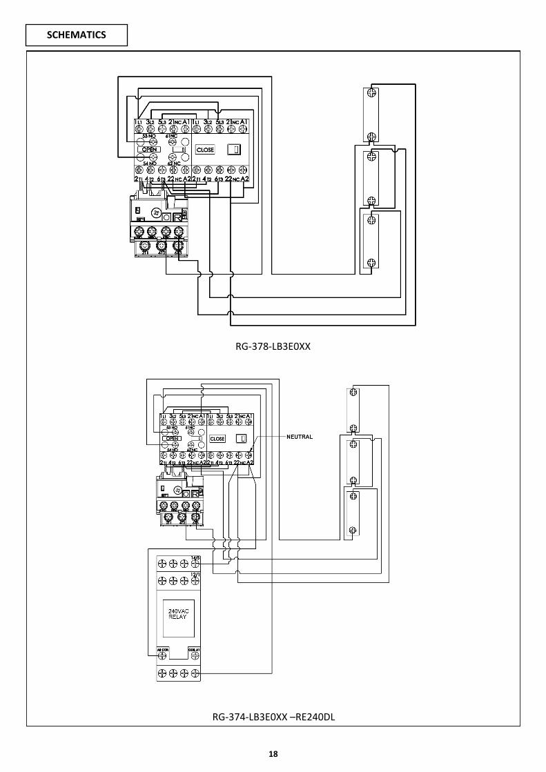
SCHEMATICS
RG-378-LB3E0XX
RG-374-LB3E0XX –RE240DL

19
© 2015 The Chamberlain Group, Inc
CHAMBERLAIN LIMITED WARRANTY - Grifco Products
Chamberlain Australia Pty Limited / Chamberlain New Zealand Limited (Chamberlain) is committed to manufacturing and supplying high quality goods. As part of
this commitment, we seek to provide reliable service and support for our goods and are pleased to provide you, the original purchaser, with this Chamberlain
Limited Warranty.
We also provide the following statement as required by the Australian Consumer Law: In Australia, in addition to your rights under this Chamberlain Limited
Warranty, our goods come with guarantees that cannot be excluded under the Australian Consumer Law. You are entitled to a replacement or refund for a ma-
jor failure and for compensation for any other reasonably foreseeable loss or damage. You are also entitled to have the goods repaired or replaced if the goods
fail to be of acceptable quality and the failure does not amount to a major failure.
Chamberlain’s warranty
Chamberlain warrants to the original purchaser of the Grifco product (Unit) that:
1 The Unit (excluding the electric motor) is free from defects in materials and workmanship for a period of 24 months from the date of purchase.
2 The electric motor is free from defects in materials and workmanship for a period of 12 months from the date of purchase.
During the applicable Chamberlain Warranty period, if you are concerned that the Unit or electric motor may be defective, call our service centre on the toll free
number below before removing the Unit and a Chamberlain technician will diagnose the problem. Once the problem has been diagnosed, subject to your rights
under the Australian Consumer Law with respect to major failures, Chamberlain will provide you with:
1 parts for “do-it-yourself” repairs; or
2 shipping instructions for a factory repair or replacement.
If a factory repair or replacement is required, provided the defective part or Unit is returned to Chamberlain well-packaged and in accordance with Chamberlain’s
shipping instructions, Chamberlain will, subject to your rights under the Australian Consumer Law with respect to major failures:
1 in relation to the Unit (excluding the electric motor), repair or, at its option where permissible, replace any defective part or Unit (excluding the electric mo-
tor) and return it to you at no cost; and
2 in relation to the electric motor, replace the electric motor and return it to you at no cost.
Where the Unit has been installed by an authorised installer, you must call them for prompt on-site service. Chamberlain will furnish replacement parts free of
charge through the authorised installer. A service fee for on-site service may apply.
Repairs and replacement parts provided under this Chamberlain Limited Warranty are provided free of charge and are warranted for the remaining portion of
the original warranty period.
This Chamberlain Limited Warranty provides benefits which are in addition to your other rights and remedies as a consumer.
Exclusions
If our service centre determines that a warranty claim has been made in respect of a failure or defect arising under or out of any exclusion detailed below such
that the claim is not covered under this Chamberlain Limited Warranty, we may, subject to your other rights and remedies as a consumer, charge you a fee to
repair, replace and/or return the Unit to you.
This Chamberlain Limited Warranty does not cover any failure of, or defect in, the Unit due to:
1 non-compliance with the instructions regarding installation, operation, maintenance and testing of the Unit or of any product with which the Unit is used;
2 any attempt by a person other than an authorised installer to change settings, repair, dismantle, reinstall or move the Unit to another location once it has
been installed;
3 tampering, neglect, abuse, wear and tear, accident, electrical storm, excessive use or conditions other than normal commercial use;
4 use of the Unit in conjunction with controls which have not been supplied, or pre-approved, by Chamberlain;
5 problems with, or relating to, the commercial door or commercial door hardware, including but not limited to the door springs, door rollers, door alignment,
hinges, guides, slats and drums; or
6 problems caused by electrical faults.
If this Chamberlain Limited Warranty does not apply, you may have rights available to you under the Australian Consumer Law.
Liability – Australia only
Except as set out in the Australian Consumer Law (being Schedule 2 of the Competition and Consumer Act 2010) (as amended, consolidated or replaced):
1 all other guarantees, warranties and representations in relation to the Unit or its supply are excluded to the extent that Chamberlain can lawfully exclude
them; and
2 under no circumstances will Chamberlain be liable for consequential, incidental or special damages arising in connection with the use, or inability to use, the
Unit, other than those which were reasonably foreseeable as liable to result from the failure.
Liability – New Zealand only
Except as set out in the Fair Trading Act 1986 and the Consumer Guarantees Act 1993 (as amended, consolidated or replaced):
1 all other guarantees, warranties and representations in relation to the Unit or its supply are excluded to the extent that Chamberlain can lawfully exclude
them; and
2 under no circumstances will Chamberlain be liable for consequential, incidental or special damages arising in connection with the use, or inability to use, the
Unit, other than those which were reasonably foreseeable as liable to result from the failure.
Note
We request that you retain your sales docket or invoice as proof-of-purchase and attach it to this manual to enable you to establish the date of purchase in the
unlikely event of a warranty service being required. Chamberlain reserves the right to change the design and specifications of the Unit without prior notification.
Some features or accessories of the Unit may not be available in certain markets or areas. Please check with your distributor.
New Zealand Auckland phone 09 477 2823 Phone toll free 0800 653 667 Fax toll free 0800 653 663
Websites www.grifco.com.au or www.grifco.co.nz
Chamberlain service centre contact details Australia Phone toll free 1800 474 326 Fax toll free 1800 888 121 Unit 1, 75 Epping Road North Ryde, NSW 2113
Email [email protected]


![Reversing and Malware Analysis Training Articles [2012] . cracking/Reversing... · Reversing and Malware Analysis Training Articles ... Step 1: Start with what you ... Reversing and](https://static.fdocuments.in/doc/165x107/5ab905fd7f8b9ac10d8db0ab/reversing-and-malware-analysis-training-articles-2012-crackingreversingreversing.jpg)