
Rg1200 1st Stage
63
Dive Rite RG 1200 Regulator • Service and Repair Manual Page 1 RG1200 Service and Repair Manual First Stage . . . . . . . . . . . . . . . . . . . . . . . . . . . . . . . . . . . . . . . . . 2 Disassembly . . . . . . . . . . . . . . . . . . . . . . . . . . . . . . . . . . . . . . . . . . . . 3 Cleaning . . . . . . . . . . . . . . . . . . . . . . . . . . . . . . . . . . . . . . . . . . . . . 12 Reassembly . . . . . . . . . . . . . . . . . . . . . . . . . . . . . . . . . . . . . . . . . . . 13 Adjustable Second Stage . . . . . . . . . . . . . . . . . . . . . . . . . . . . 23 Disassembly . . . . . . . . . . . . . . . . . . . . . . . . . . . . . . . . . . . . . . . . . . . 24 Cleaning . . . . . . . . . . . . . . . . . . . . . . . . . . . . . . . . . . . . . . . . . . . . . 33 Reassembly . . . . . . . . . . . . . . . . . . . . . . . . . . . . . . . . . . . . . . . . . . . 33 Non-Adjustable Second Stage . . . . . . . . . . . . . . . . . . . . . . . . 43 Disassembly . . . . . . . . . . . . . . . . . . . . . . . . . . . . . . . . . . . . . . . . . . . 43 Cleaning . . . . . . . . . . . . . . . . . . . . . . . . . . . . . . . . . . . . . . . . . . . . . 49 Reassembly . . . . . . . . . . . . . . . . . . . . . . . . . . . . . . . . . . . . . . . . . . . 49 Adjustment . . . . . . . . . . . . . . . . . . . . . . . . . . . . . . . . . . . . . . . . 55 First Stage . . . . . . . . . . . . . . . . . . . . . . . . . . . . . . . . . . . . . . . . . . . . 55 Second Stage . . . . . . . . . . . . . . . . . . . . . . . . . . . . . . . . . . . . . . . . . . 56 Troubleshooting . . . . . . . . . . . . . . . . . . . . . . . . . . . . . . . . . . . . 58 Cold Water Kit Installation . . . . . . . . . . . . . . . . . . . . . . . . . . . . 60 Parts Diagrams . . . . . . . . . . . . . . . . . . . . . . . . . . . . . . . . . . . . 61 First Stage . . . . . . . . . . . . . . . . . . . . . . . . . . . . . . . . . . . . . . . . . . . . 61 Adjustable Second Stage . . . . . . . . . . . . . . . . . . . . . . . . . . . . . . . . . . 62 Non-Adjustable Second Stage . . . . . . . . . . . . . . . . . . . . . . . . . . . . . . 63 Text and Photography by Pete Nawrocky Copyright (©) 1999-2000, Lamartek, Inc., dba Dive Rite
-
Upload
mitchell-singler -
Category
Documents
-
view
33 -
download
0
Transcript of Rg1200 1st Stage
Dive Rite RG 1200 Regulator • Service and Repair Manual Page 1
RG1200 Serviceand Repair Manual
First Stage . . . . . . . . . . . . . . . . . . . . . . . . . . . . . . . . . . . . . . . . . 2Disassembly . . . . . . . . . . . . . . . . . . . . . . . . . . . . . . . . . . . . . . . . . . . . 3Cleaning . . . . . . . . . . . . . . . . . . . . . . . . . . . . . . . . . . . . . . . . . . . . . 12Reassembly . . . . . . . . . . . . . . . . . . . . . . . . . . . . . . . . . . . . . . . . . . . 13
Adjustable Second Stage . . . . . . . . . . . . . . . . . . . . . . . . . . . . 23Disassembly . . . . . . . . . . . . . . . . . . . . . . . . . . . . . . . . . . . . . . . . . . . 24Cleaning . . . . . . . . . . . . . . . . . . . . . . . . . . . . . . . . . . . . . . . . . . . . . 33Reassembly . . . . . . . . . . . . . . . . . . . . . . . . . . . . . . . . . . . . . . . . . . . 33
Non-Adjustable Second Stage . . . . . . . . . . . . . . . . . . . . . . . . 43Disassembly . . . . . . . . . . . . . . . . . . . . . . . . . . . . . . . . . . . . . . . . . . . 43Cleaning . . . . . . . . . . . . . . . . . . . . . . . . . . . . . . . . . . . . . . . . . . . . . 49Reassembly . . . . . . . . . . . . . . . . . . . . . . . . . . . . . . . . . . . . . . . . . . . 49
Adjustment. . . . . . . . . . . . . . . . . . . . . . . . . . . . . . . . . . . . . . . . 55First Stage . . . . . . . . . . . . . . . . . . . . . . . . . . . . . . . . . . . . . . . . . . . . 55Second Stage . . . . . . . . . . . . . . . . . . . . . . . . . . . . . . . . . . . . . . . . . . 56
Troubleshooting. . . . . . . . . . . . . . . . . . . . . . . . . . . . . . . . . . . . 58
Cold Water Kit Installation . . . . . . . . . . . . . . . . . . . . . . . . . . . . 60
Parts Diagrams . . . . . . . . . . . . . . . . . . . . . . . . . . . . . . . . . . . . 61First Stage . . . . . . . . . . . . . . . . . . . . . . . . . . . . . . . . . . . . . . . . . . . . 61Adjustable Second Stage . . . . . . . . . . . . . . . . . . . . . . . . . . . . . . . . . . 62Non-Adjustable Second Stage . . . . . . . . . . . . . . . . . . . . . . . . . . . . . . 63
Text and Photographyby Pete Nawrocky
Copyright (©) 1999-2000, Lamartek, Inc., dba Dive Rite
Dive Rite RG 1200 Regulator • Service and Repair Manual Page 2
This manual is only to be used as a guide for trained regulatortechnician. Possession of this guide does not qualify any individ-ual to service Dive Rite breathing systems. Only qualified DiveRite dealers may service Dive Rite Products. Improper servicingcan lead to serious injury or death.
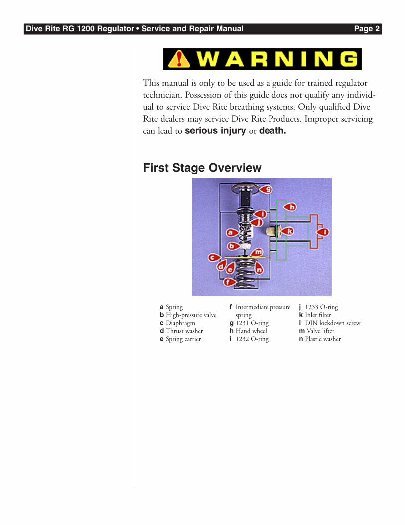
First Stage Overview
a Springb High-pressure valvec Diaphragmd Thrust washere Spring carrier
f Intermediate pressurespring
g 1231 O-ringh Hand wheeli 1232 O-ring
j 1233 O-ringk Inlet filterl DIN lockdown screwm Valve liftern Plastic washer
Dive Rite RG 1200 Regulator • Service and Repair Manual Page 3
First Stage DisassemblyBefore you begin:
�Remove all low-pressure hoses.
�Remove high-pressure hoses and remaining port plugs.
�Note location of plugs and hoses.
Then perform the following steps, in order.
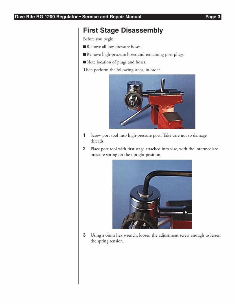
1 Screw port tool into high-pressure port. Take care not to damagethreads.
2 Place port tool with first stage attached into vise, with the intermediatepressure spring on the upright position.
3 Using a 6mm hex wrench, loosen the adjustment screw enough to lessenthe spring tension.
Dive Rite RG 1200 Regulator • Service and Repair Manual Page 4
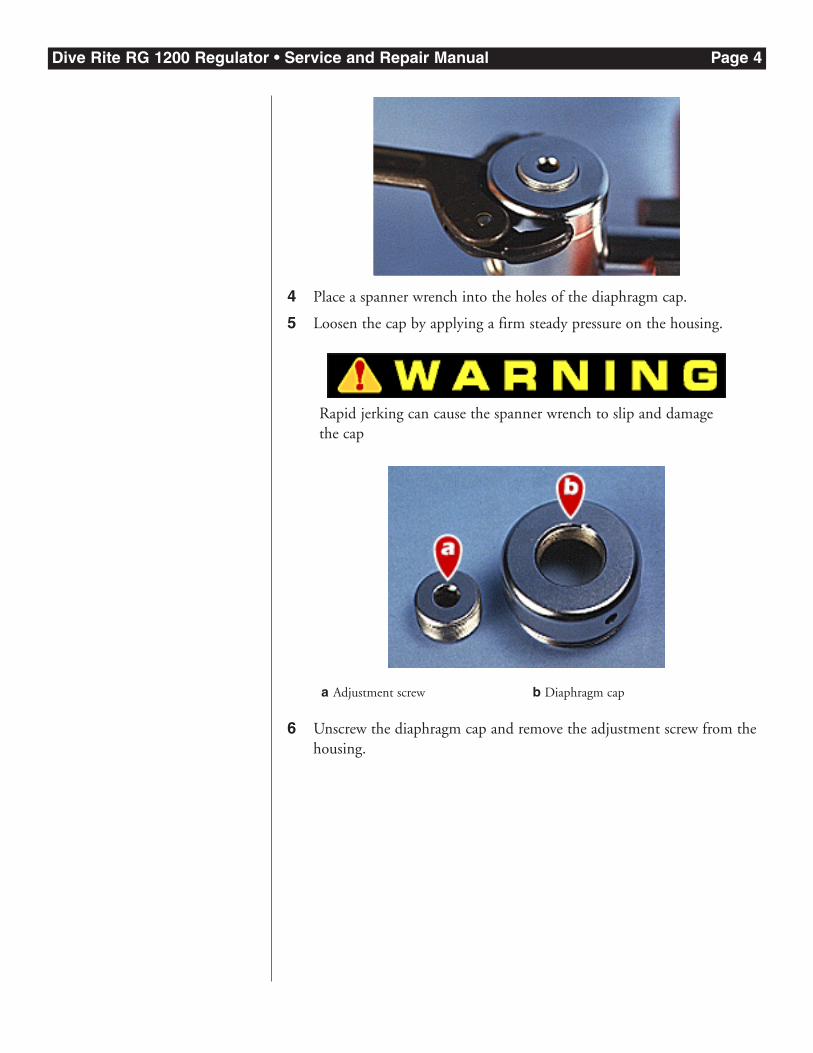
4 Place a spanner wrench into the holes of the diaphragm cap.
5 Loosen the cap by applying a firm steady pressure on the housing.
Rapid jerking can cause the spanner wrench to slip and damagethe cap
6 Unscrew the diaphragm cap and remove the adjustment screw from thehousing.
a Adjustment screw b Diaphragm cap
Dive Rite RG 1200 Regulator • Service and Repair Manual Page 5
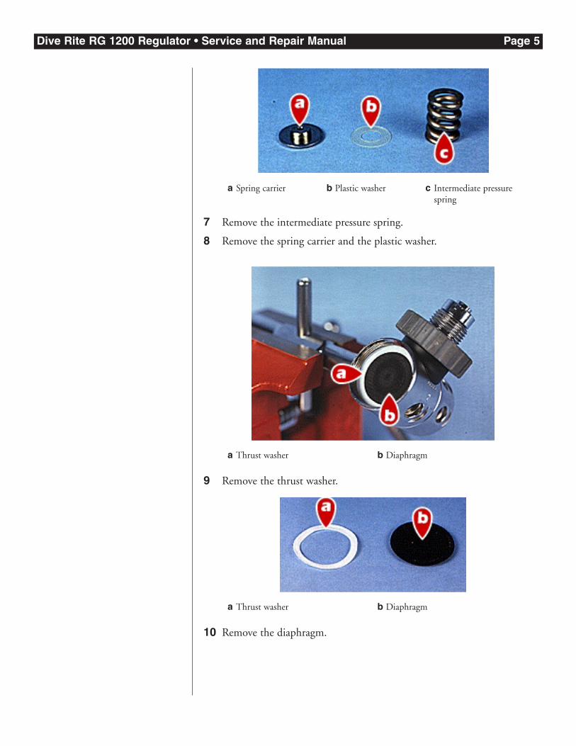
7 Remove the intermediate pressure spring.
8 Remove the spring carrier and the plastic washer.
9 Remove the thrust washer.
10 Remove the diaphragm.
a Thrust washer b Diaphragm
a Thrust washer b Diaphragm
a Spring carrier b Plastic washer c Intermediate pressurespring
Dive Rite RG 1200 Regulator • Service and Repair Manual Page 6
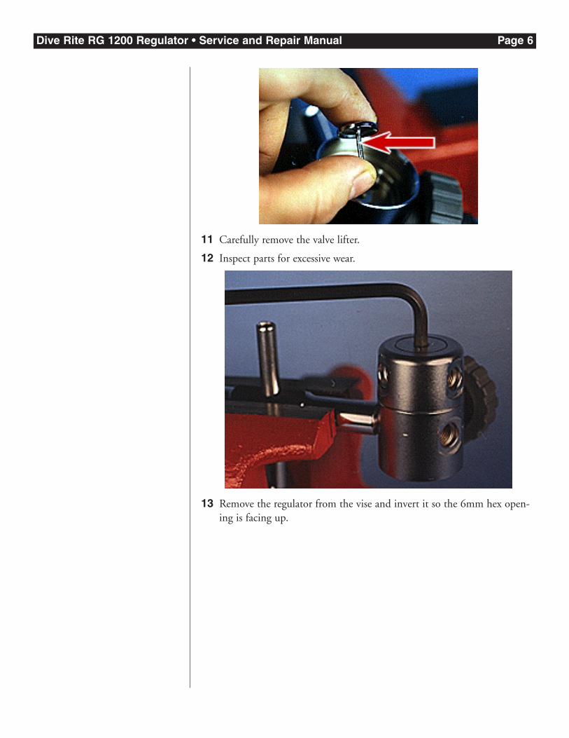
11 Carefully remove the valve lifter.
12 Inspect parts for excessive wear.
13 Remove the regulator from the vise and invert it so the 6mm hex open-ing is facing up.
Dive Rite RG 1200 Regulator • Service and Repair Manual Page 7
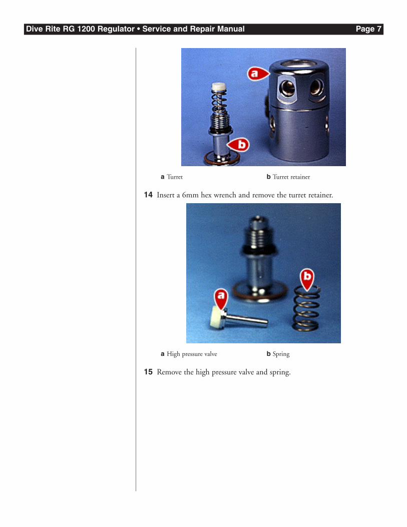
14 Insert a 6mm hex wrench and remove the turret retainer.
15 Remove the high pressure valve and spring.
a High pressure valve b Spring
a Turret b Turret retainer
Dive Rite RG 1200 Regulator • Service and Repair Manual Page 8
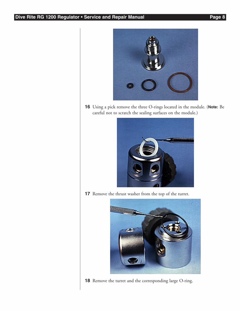
16 Using a pick remove the three O-rings located in the module. (Note: Becareful not to scratch the sealing surfaces on the module.)
17 Remove the thrust washer from the top of the turret.
18 Remove the turret and the corresponding large O-ring.
Dive Rite RG 1200 Regulator • Service and Repair Manual Page 9
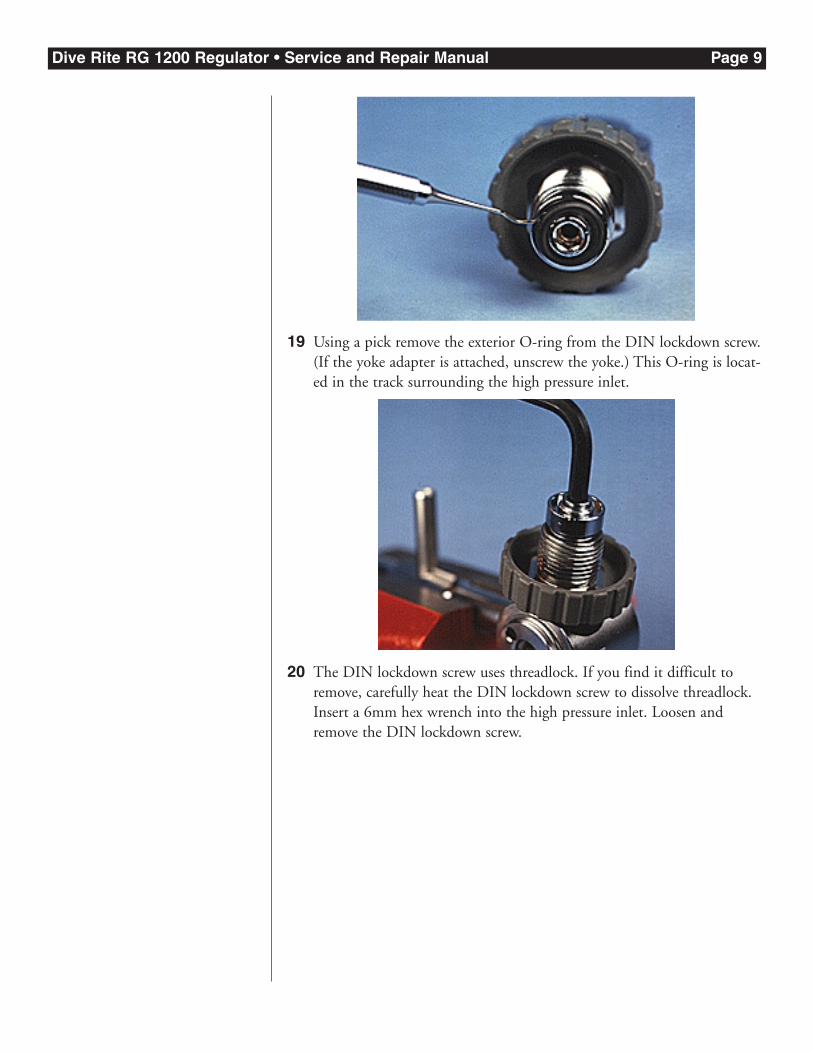
19 Using a pick remove the exterior O-ring from the DIN lockdown screw.(If the yoke adapter is attached, unscrew the yoke.) This O-ring is locat-ed in the track surrounding the high pressure inlet.
20 The DIN lockdown screw uses threadlock. If you find it difficult toremove, carefully heat the DIN lockdown screw to dissolve threadlock.Insert a 6mm hex wrench into the high pressure inlet. Loosen andremove the DIN lockdown screw.
Dive Rite RG 1200 Regulator • Service and Repair Manual Page 10
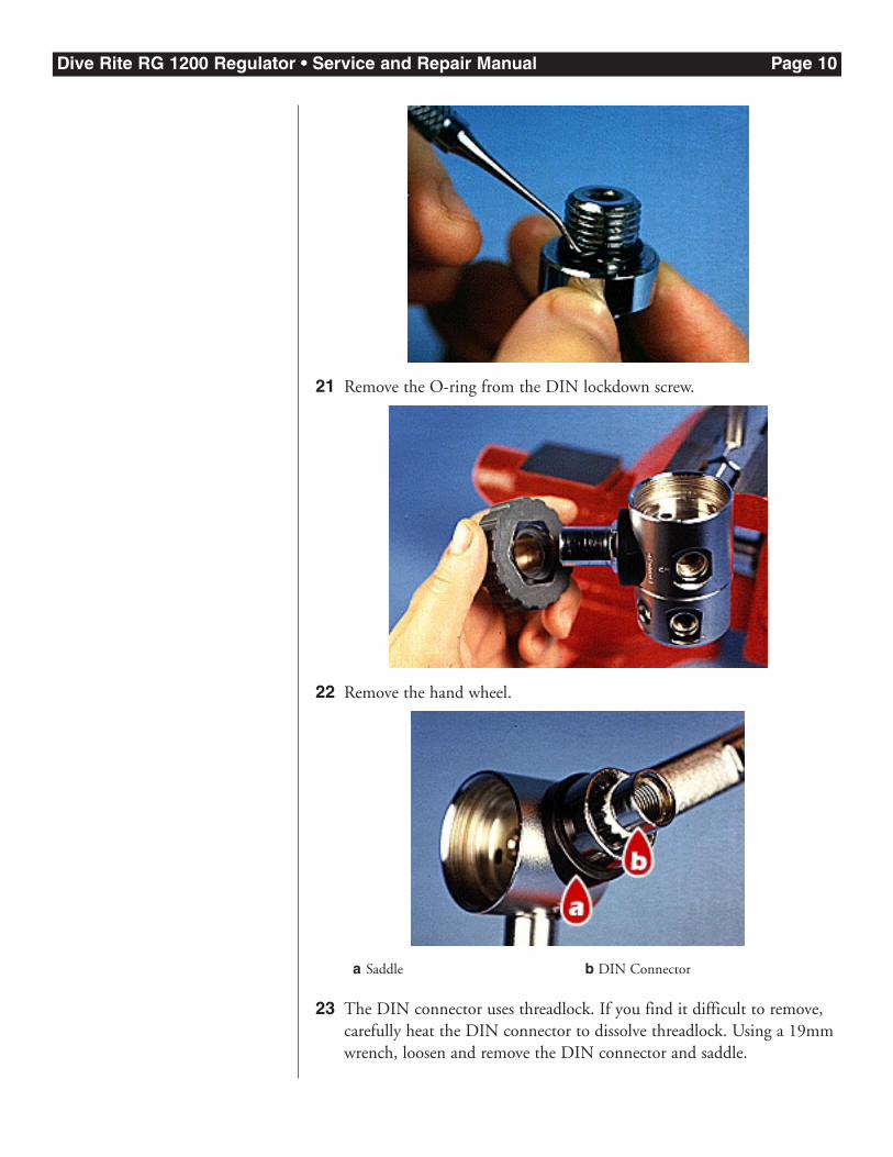
21 Remove the O-ring from the DIN lockdown screw.
22 Remove the hand wheel.
23 The DIN connector uses threadlock. If you find it difficult to remove,carefully heat the DIN connector to dissolve threadlock. Using a 19mmwrench, loosen and remove the DIN connector and saddle.
a Saddle b DIN Connector
Dive Rite RG 1200 Regulator • Service and Repair Manual Page 11
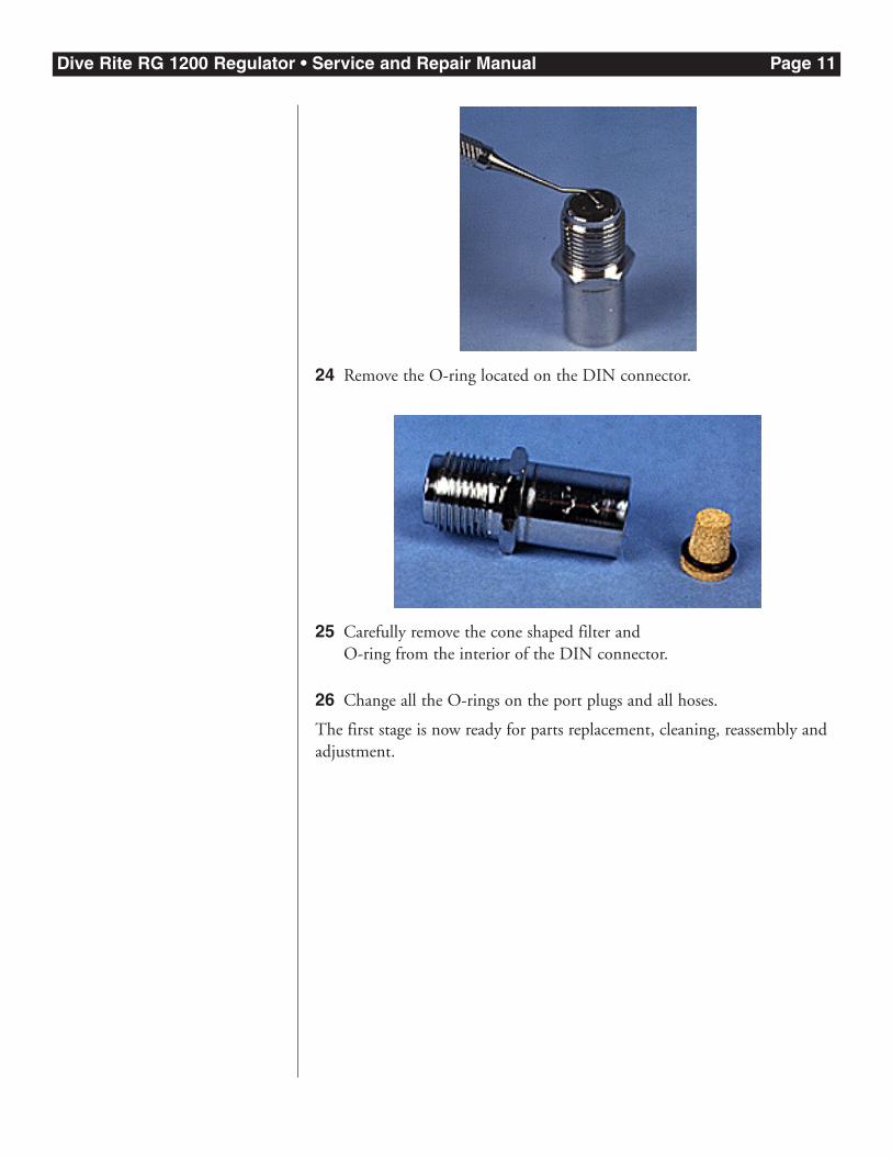
24 Remove the O-ring located on the DIN connector.
25 Carefully remove the cone shaped filter and O-ring from the interior of the DIN connector.
26 Change all the O-rings on the port plugs and all hoses.
The first stage is now ready for parts replacement, cleaning, reassembly andadjustment.
Dive Rite RG 1200 Regulator • Service and Repair Manual Page 12
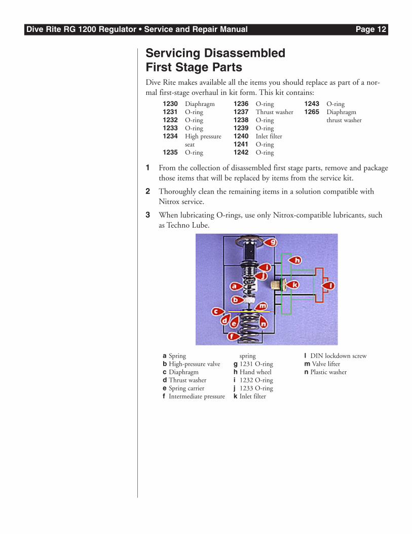
Servicing Disassembled First Stage PartsDive Rite makes available all the items you should replace as part of a nor-mal first-stage overhaul in kit form. This kit contains:
1 From the collection of disassembled first stage parts, remove and packagethose items that will be replaced by items from the service kit.
2 Thoroughly clean the remaining items in a solution compatible withNitrox service.
3 When lubricating O-rings, use only Nitrox-compatible lubricants, suchas Techno Lube.
a Springb High-pressure valvec Diaphragmd Thrust washere Spring carrierf Intermediate pressure
springg 1231 O-ringh Hand wheeli 1232 O-ringj 1233 O-ringk Inlet filter
l DIN lockdown screwm Valve liftern Plastic washer
1230 Diaphragm1231 O-ring1232 O-ring1233 O-ring1234 High pressure
seat1235 O-ring
1236 O-ring1237 Thrust washer1238 O-ring1239 O-ring1240 Inlet filter1241 O-ring1242 O-ring
1243 O-ring1265 Diaphragm
thrust washer
Dive Rite RG 1200 Regulator • Service and Repair Manual Page 13
First Stage Reassembly
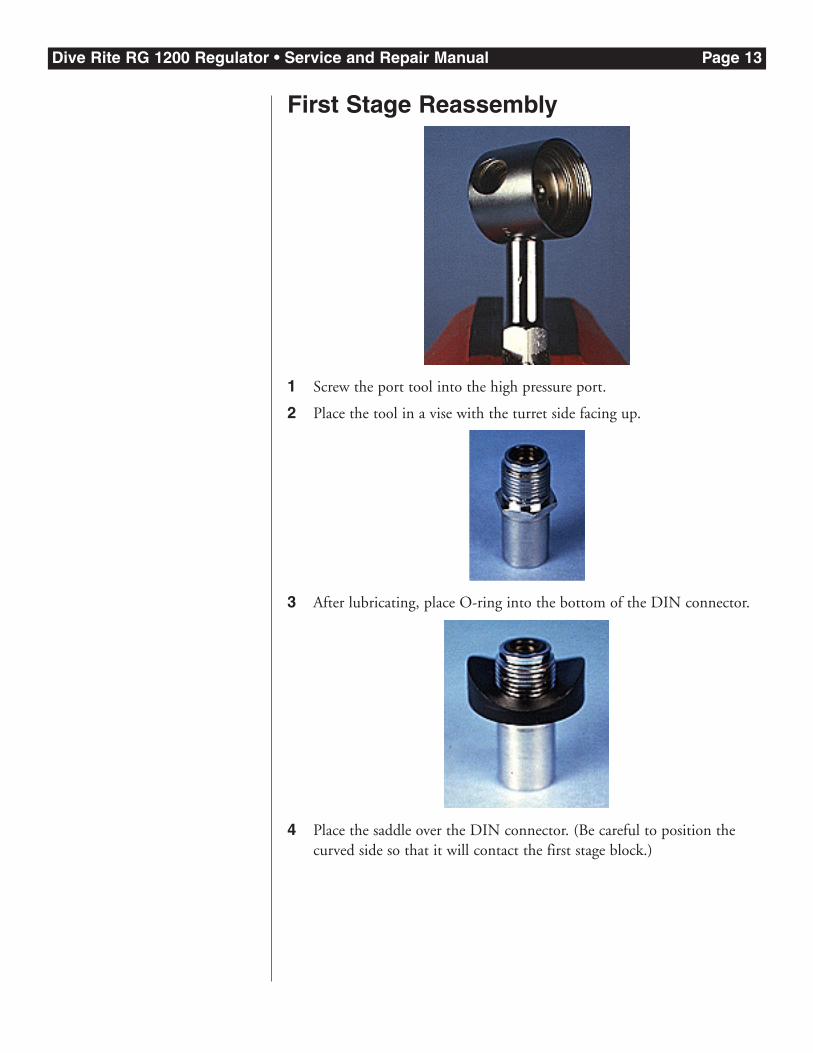
1 Screw the port tool into the high pressure port.
2 Place the tool in a vise with the turret side facing up.
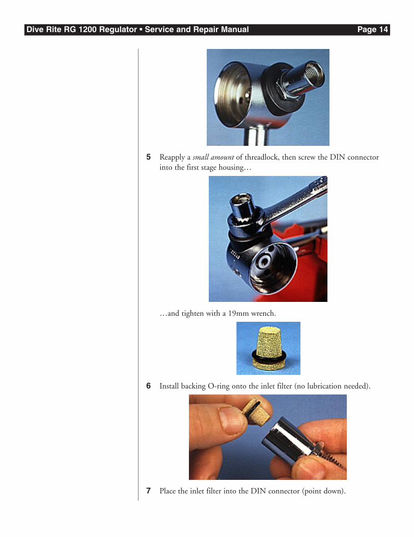
3 After lubricating, place O-ring into the bottom of the DIN connector.
4 Place the saddle over the DIN connector. (Be careful to position thecurved side so that it will contact the first stage block.)
Dive Rite RG 1200 Regulator • Service and Repair Manual Page 14
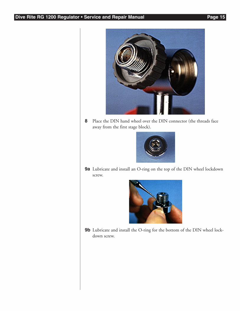
5 Reapply a small amount of threadlock, then screw the DIN connectorinto the first stage housing…
…and tighten with a 19mm wrench.
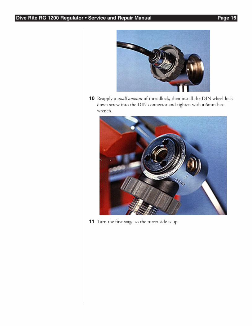
6 Install backing O-ring onto the inlet filter (no lubrication needed).
7 Place the inlet filter into the DIN connector (point down).
Dive Rite RG 1200 Regulator • Service and Repair Manual Page 15
8 Place the DIN hand wheel over the DIN connector (the threads faceaway from the first stage block).
9a Lubricate and install an O-ring on the top of the DIN wheel lockdownscrew.
9b Lubricate and install the O-ring for the bottom of the DIN wheel lock-down screw.
Dive Rite RG 1200 Regulator • Service and Repair Manual Page 16
10 Reapply a small amount of threadlock, then install the DIN wheel lock-down screw into the DIN connector and tighten with a 6mm hexwrench.
11 Turn the first stage so the turret side is up.
Dive Rite RG 1200 Regulator • Service and Repair Manual Page 17
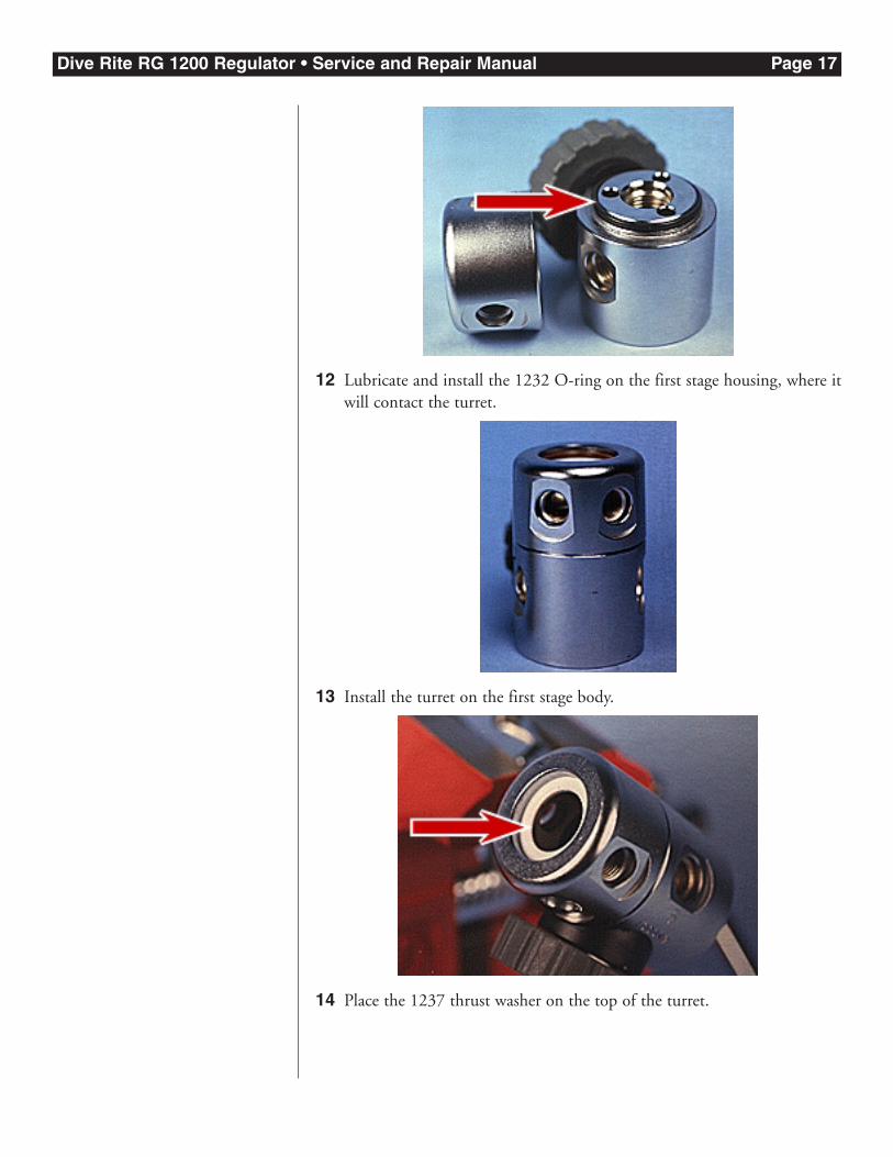
12 Lubricate and install the 1232 O-ring on the first stage housing, where itwill contact the turret.
13 Install the turret on the first stage body.
14 Place the 1237 thrust washer on the top of the turret.
Dive Rite RG 1200 Regulator • Service and Repair Manual Page 18
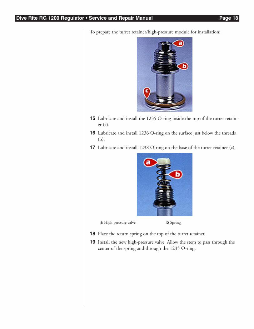
To prepare the turret retainer/high-pressure module for installation:
15 Lubricate and install the 1235 O-ring inside the top of the turret retain-er (a).
16 Lubricate and install 1236 O-ring on the surface just below the threads(b).
17 Lubricate and install 1238 O-ring on the base of the turret retainer (c).
18 Place the return spring on the top of the turret retainer.
19 Install the new high-pressure valve. Allow the stem to pass through thecenter of the spring and through the 1235 O-ring.
a High pressure valve b Spring
Dive Rite RG 1200 Regulator • Service and Repair Manual Page 19
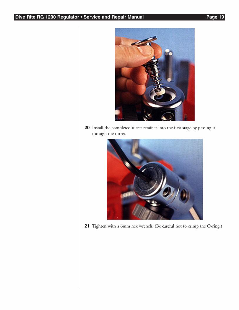
20 Install the completed turret retainer into the first stage by passing itthrough the turret.
21 Tighten with a 6mm hex wrench. (Be careful not to crimp the O-ring.)
Dive Rite RG 1200 Regulator • Service and Repair Manual Page 20
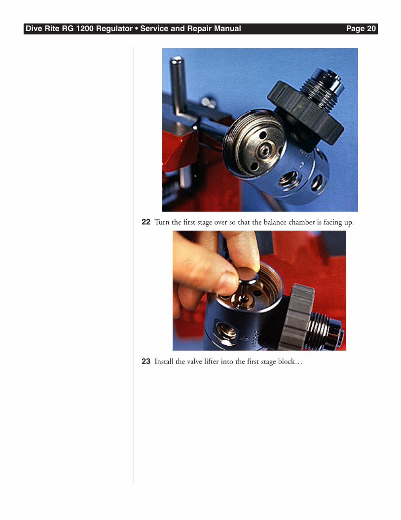
22 Turn the first stage over so that the balance chamber is facing up.
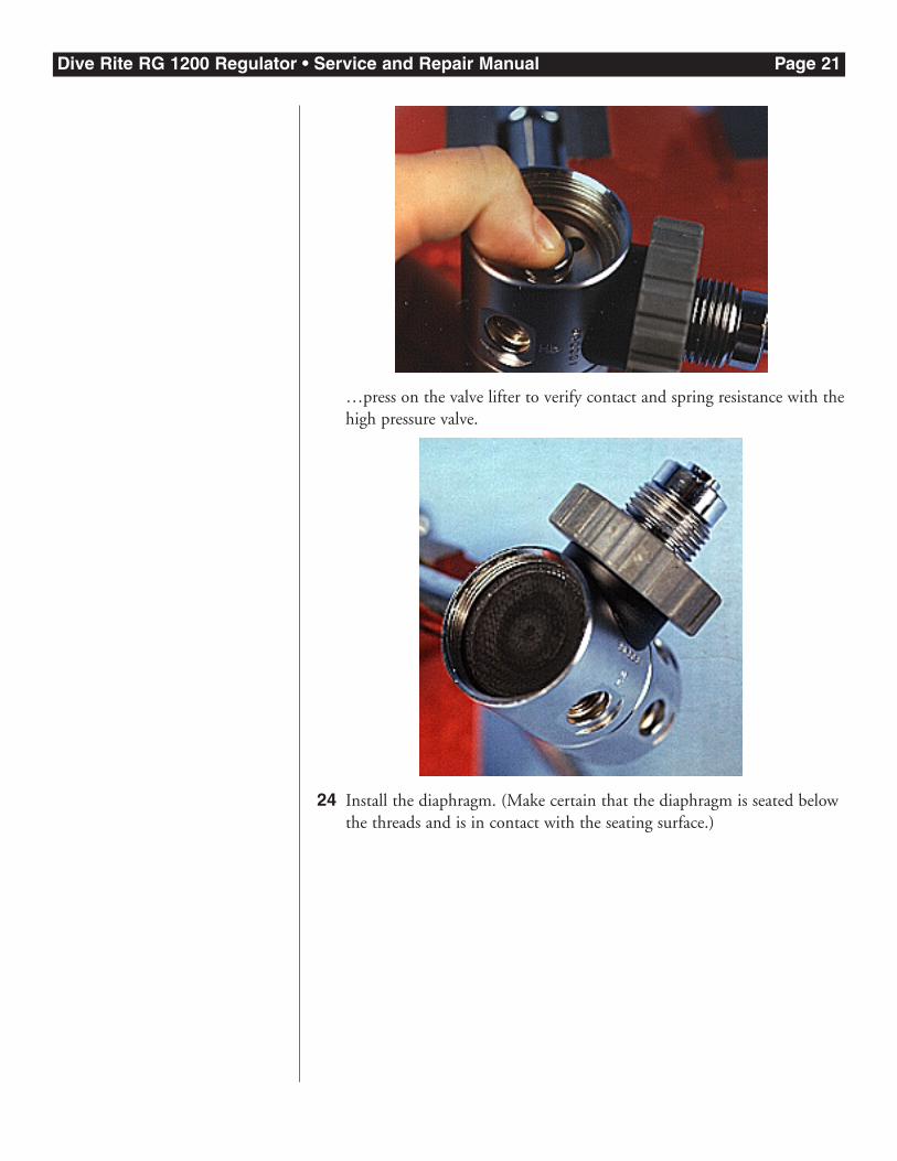
23 Install the valve lifter into the first stage block…
Dive Rite RG 1200 Regulator • Service and Repair Manual Page 21
…press on the valve lifter to verify contact and spring resistance with thehigh pressure valve.
24 Install the diaphragm. (Make certain that the diaphragm is seated belowthe threads and is in contact with the seating surface.)
Dive Rite RG 1200 Regulator • Service and Repair Manual Page 22
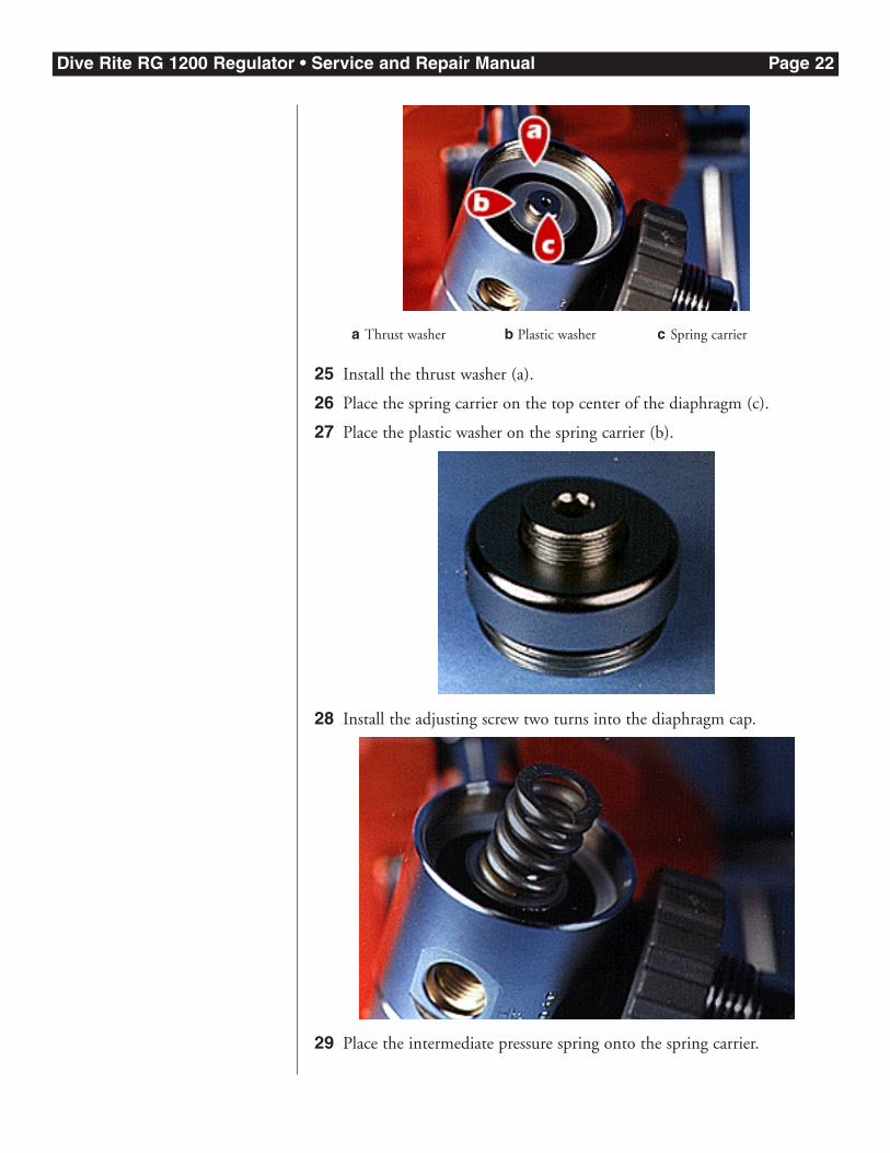
25 Install the thrust washer (a).
26 Place the spring carrier on the top center of the diaphragm (c).
27 Place the plastic washer on the spring carrier (b).
28 Install the adjusting screw two turns into the diaphragm cap.
29 Place the intermediate pressure spring onto the spring carrier.
a Thrust washer b Plastic washer c Spring carrier
Dive Rite RG 1200 Regulator • Service and Repair Manual Page 23
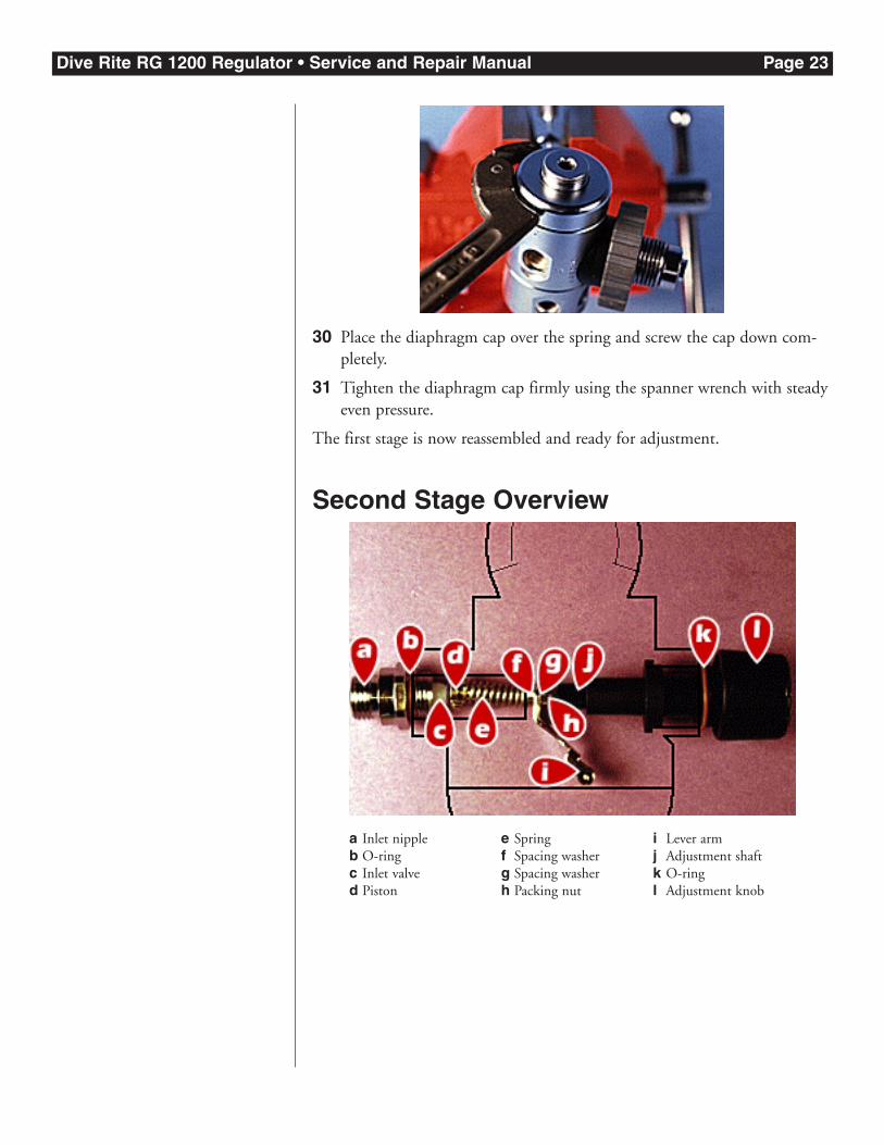
30 Place the diaphragm cap over the spring and screw the cap down com-pletely.
31 Tighten the diaphragm cap firmly using the spanner wrench with steadyeven pressure.
The first stage is now reassembled and ready for adjustment.
Second Stage Overview
a Inlet nippleb O-ringc Inlet valved Piston
e Springf Spacing washerg Spacing washerh Packing nut
i Lever armj Adjustment shaftk O-ringl Adjustment knob
Dive Rite RG 1200 Regulator • Service and Repair Manual Page 24
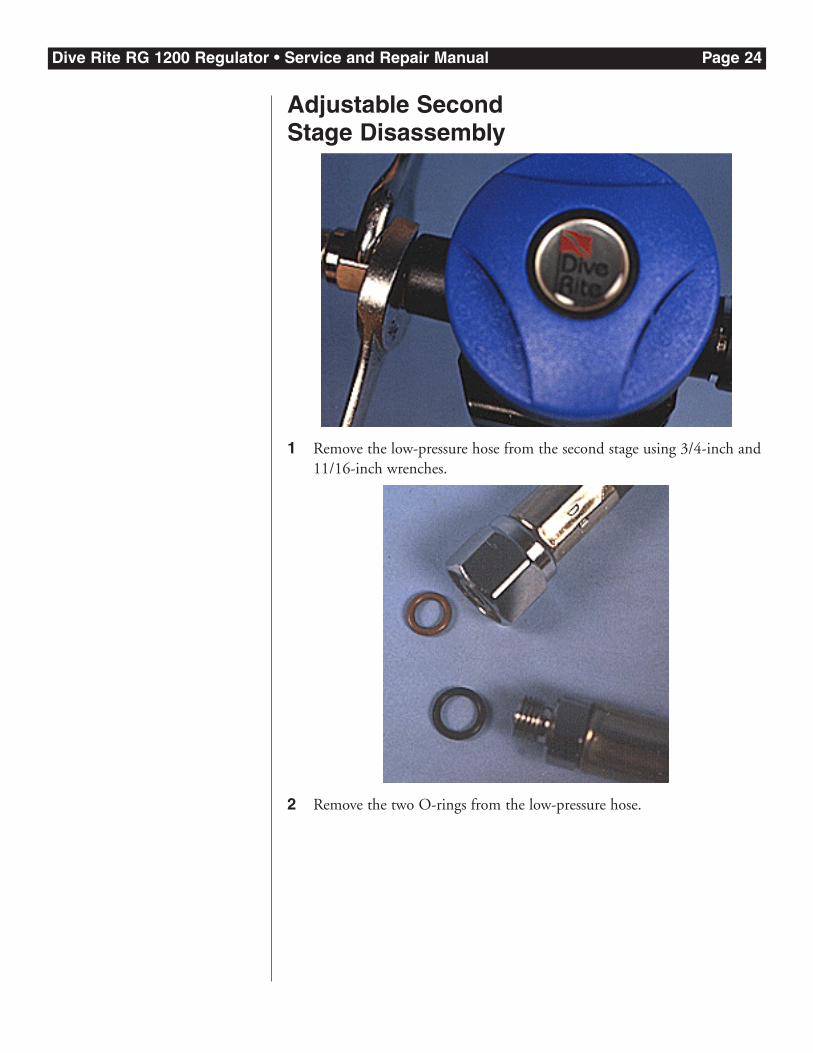
Adjustable Second Stage Disassembly
1 Remove the low-pressure hose from the second stage using 3/4-inch and11/16-inch wrenches.
2 Remove the two O-rings from the low-pressure hose.
Dive Rite RG 1200 Regulator • Service and Repair Manual Page 25
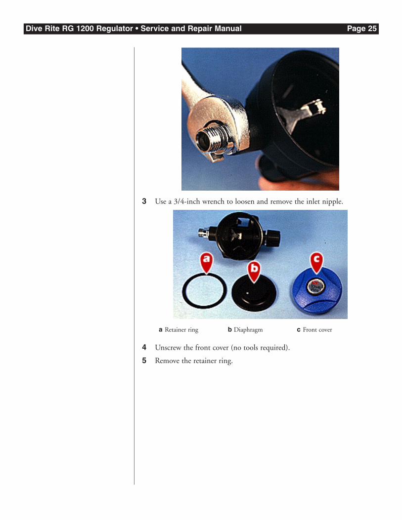
3 Use a 3/4-inch wrench to loosen and remove the inlet nipple.
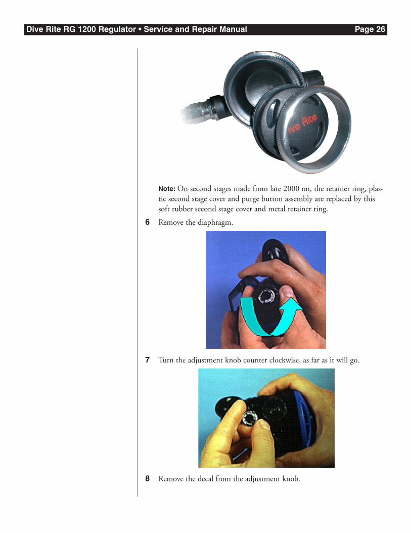
4 Unscrew the front cover (no tools required).
5 Remove the retainer ring.
a Retainer ring b Diaphragm c Front cover
Dive Rite RG 1200 Regulator • Service and Repair Manual Page 26
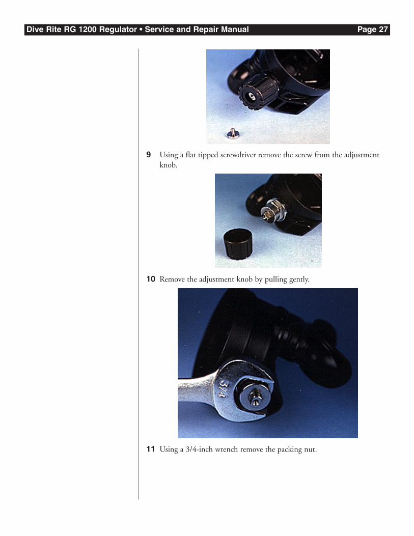
Note: On second stages made from late 2000 on, the retainer ring, plas-tic second stage cover and purge button assembly are replaced by thissoft rubber second stage cover and metal retainer ring.
6 Remove the diaphragm.
7 Turn the adjustment knob counter clockwise, as far as it will go.
8 Remove the decal from the adjustment knob.
Dive Rite RG 1200 Regulator • Service and Repair Manual Page 27
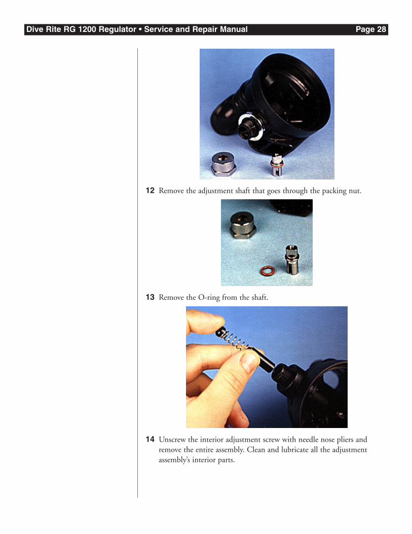
9 Using a flat tipped screwdriver remove the screw from the adjustmentknob.
10 Remove the adjustment knob by pulling gently.
11 Using a 3/4-inch wrench remove the packing nut.
Dive Rite RG 1200 Regulator • Service and Repair Manual Page 28
12 Remove the adjustment shaft that goes through the packing nut.
13 Remove the O-ring from the shaft.
14 Unscrew the interior adjustment screw with needle nose pliers andremove the entire assembly. Clean and lubricate all the adjustmentassembly’s interior parts.
Dive Rite RG 1200 Regulator • Service and Repair Manual Page 29
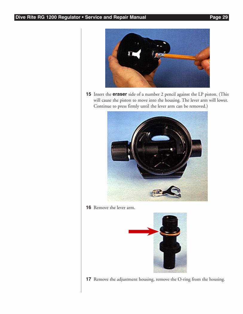
15 Insert the eraser side of a number 2 pencil against the LP piston. (Thiswill cause the piston to move into the housing. The lever arm will lower.Continue to press firmly until the lever arm can be removed.)
16 Remove the lever arm.
17 Remove the adjustment housing, remove the O-ring from the housing.
Dive Rite RG 1200 Regulator • Service and Repair Manual Page 30
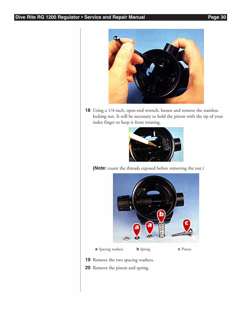
18 Using a 1/4-inch, open-end wrench, loosen and remove the stainlesslocking nut. It will be necessary to hold the piston with the tip of yourindex finger to keep it from rotating.
(Note: count the threads exposed before removing the nut.)
19 Remove the two spacing washers.
20 Remove the piston and spring.
a Spacing washers b Spring c Piston
Dive Rite RG 1200 Regulator • Service and Repair Manual Page 31
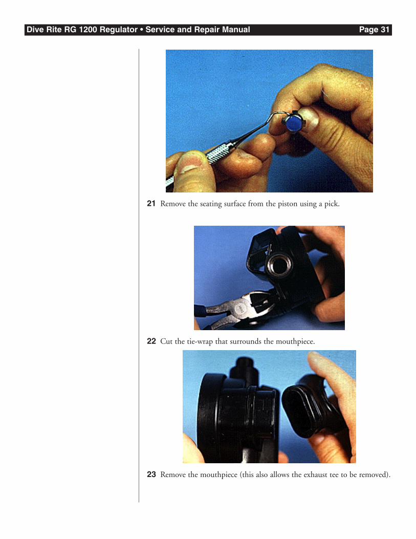
21 Remove the seating surface from the piston using a pick.
22 Cut the tie-wrap that surrounds the mouthpiece.
23 Remove the mouthpiece (this also allows the exhaust tee to be removed).
Dive Rite RG 1200 Regulator • Service and Repair Manual Page 32
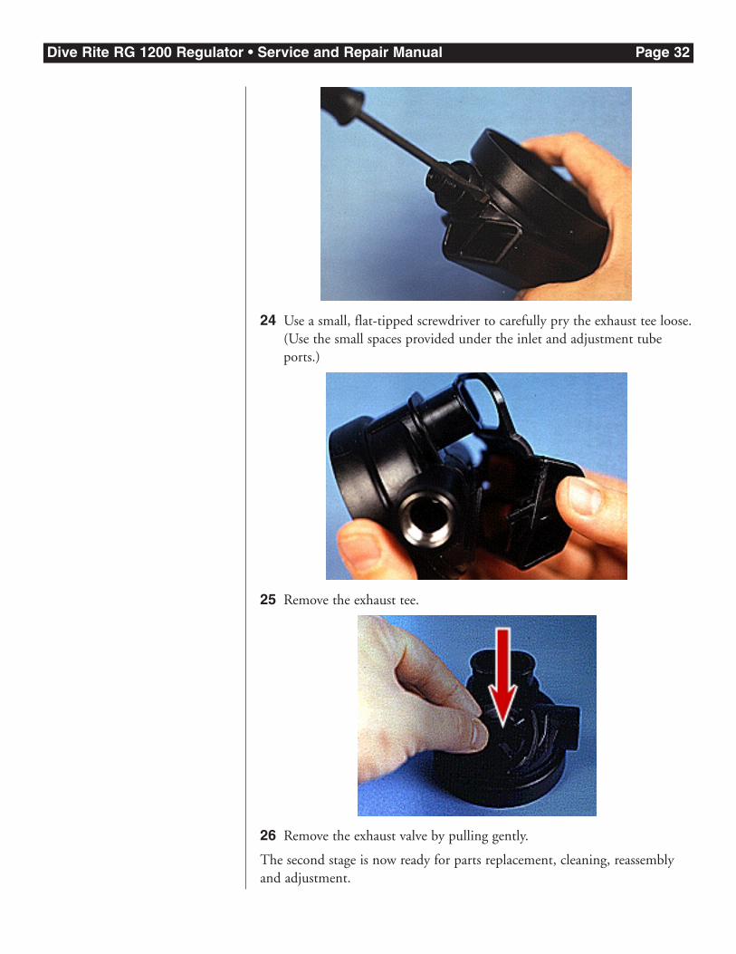
24 Use a small, flat-tipped screwdriver to carefully pry the exhaust tee loose.(Use the small spaces provided under the inlet and adjustment tubeports.)
25 Remove the exhaust tee.
26 Remove the exhaust valve by pulling gently.
The second stage is now ready for parts replacement, cleaning, reassemblyand adjustment.
Dive Rite RG 1200 Regulator • Service and Repair Manual Page 33
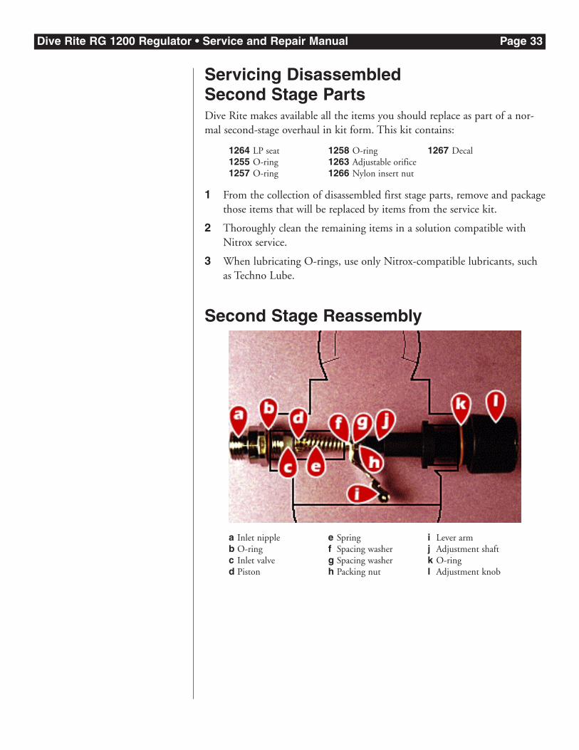
Servicing Disassembled Second Stage PartsDive Rite makes available all the items you should replace as part of a nor-mal second-stage overhaul in kit form. This kit contains:
1 From the collection of disassembled first stage parts, remove and packagethose items that will be replaced by items from the service kit.
2 Thoroughly clean the remaining items in a solution compatible withNitrox service.
3 When lubricating O-rings, use only Nitrox-compatible lubricants, suchas Techno Lube.
Second Stage Reassembly
a Inlet nippleb O-ringc Inlet valved Piston
e Springf Spacing washerg Spacing washerh Packing nut
i Lever armj Adjustment shaftk O-ringl Adjustment knob
1264 LP seat1255 O-ring1257 O-ring
1258 O-ring1263 Adjustable orifice1266 Nylon insert nut
1267 Decal
Dive Rite RG 1200 Regulator • Service and Repair Manual Page 34
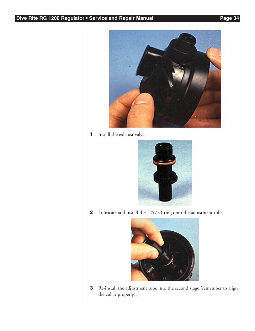
1 Install the exhaust valve.
2 Lubricate and install the 1257 O-ring onto the adjustment tube.
3 Re-install the adjustment tube into the second stage (remember to alignthe collar properly).
Dive Rite RG 1200 Regulator • Service and Repair Manual Page 35
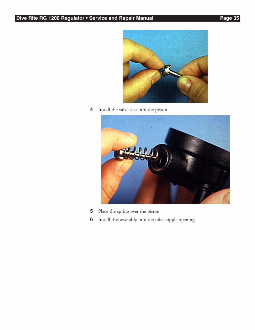
4 Install the valve seat into the piston.
5 Place the spring over the piston.
6 Install this assembly into the inlet nipple opening.
Dive Rite RG 1200 Regulator • Service and Repair Manual Page 36
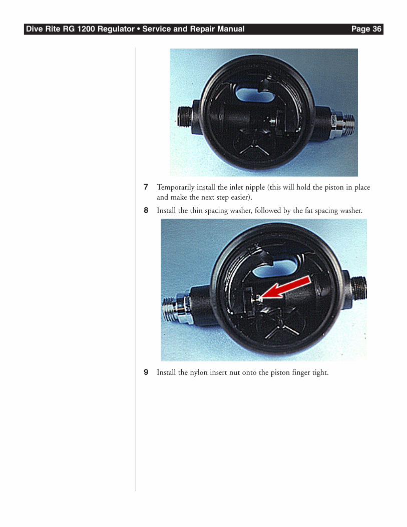
7 Temporarily install the inlet nipple (this will hold the piston in placeand make the next step easier).
8 Install the thin spacing washer, followed by the fat spacing washer.
9 Install the nylon insert nut onto the piston finger tight.
Dive Rite RG 1200 Regulator • Service and Repair Manual Page 37
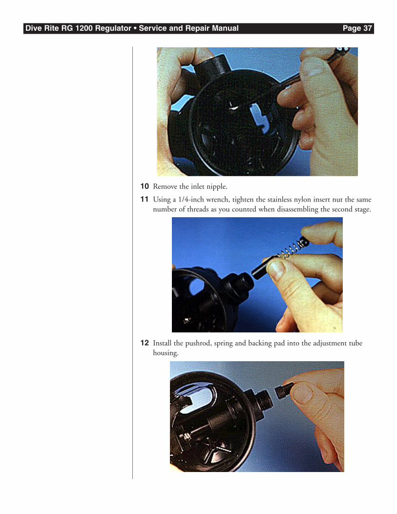
10 Remove the inlet nipple.
11 Using a 1/4-inch wrench, tighten the stainless nylon insert nut the samenumber of threads as you counted when disassembling the second stage.
12 Install the pushrod, spring and backing pad into the adjustment tubehousing.
Dive Rite RG 1200 Regulator • Service and Repair Manual Page 38
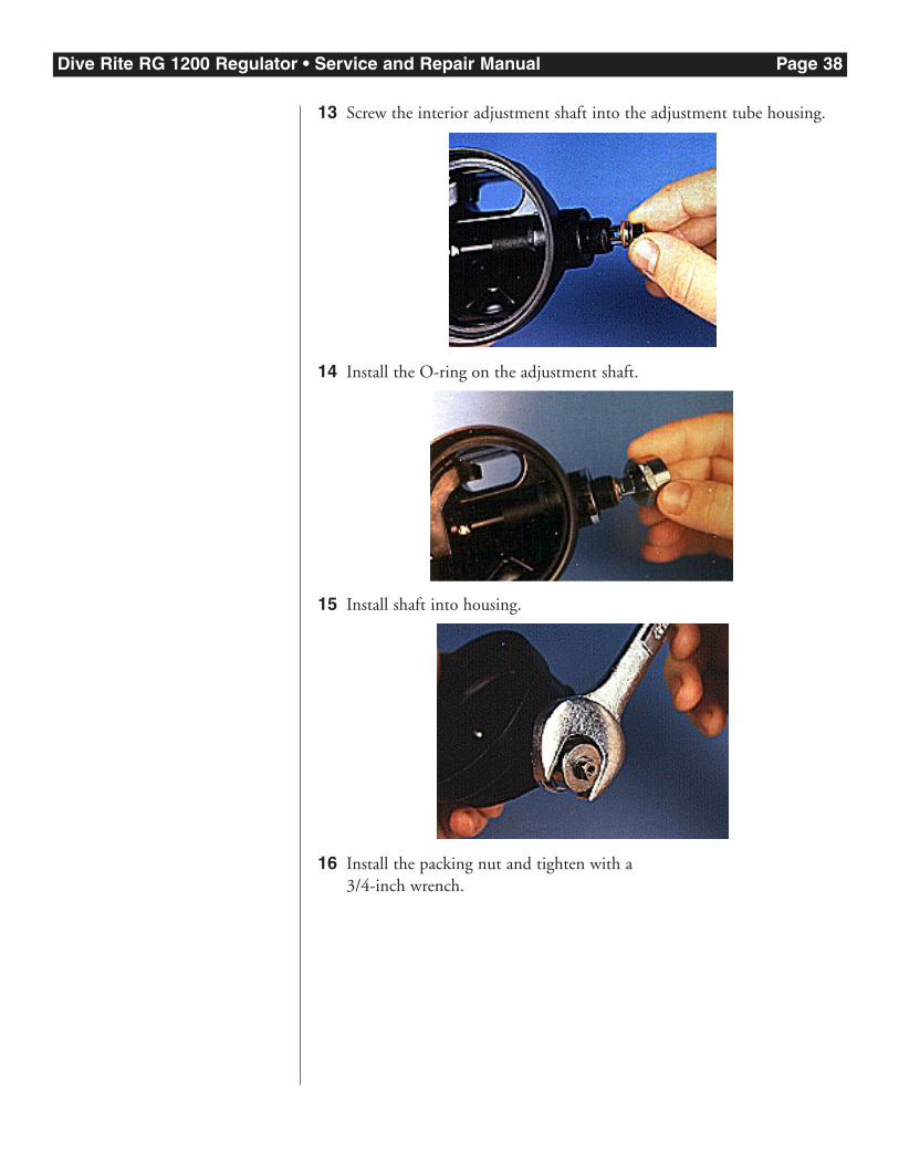
13 Screw the interior adjustment shaft into the adjustment tube housing.
14 Install the O-ring on the adjustment shaft.
15 Install shaft into housing.
16 Install the packing nut and tighten with a 3/4-inch wrench.

Dive Rite RG 1200 Regulator • Service and Repair Manual Page 39
17 Install the lockdown screw and tighten with a flat-tipped screwdriver.
18 Using the eraser of a number 2 pencil compress the piston to the pointwhere the washers are exposed.
19 Install the lever arm between the two washers.
Dive Rite RG 1200 Regulator • Service and Repair Manual Page 40
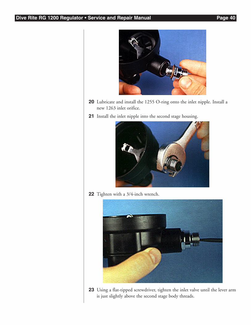
20 Lubricate and install the 1255 O-ring onto the inlet nipple. Install anew 1263 inlet orifice.
21 Install the inlet nipple into the second stage housing.
22 Tighten with a 3/4-inch wrench.
23 Using a flat-tipped screwdriver, tighten the inlet valve until the lever armis just slightly above the second stage body threads.
Dive Rite RG 1200 Regulator • Service and Repair Manual Page 41
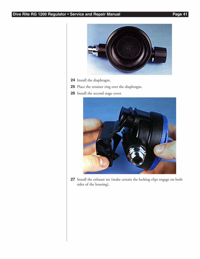
24 Install the diaphragm.
25 Place the retainer ring over the diaphragm.
26 Install the second stage cover.
27 Install the exhaust tee (make certain the locking clips engage on bothsides of the housing).
Dive Rite RG 1200 Regulator • Service and Repair Manual Page 42
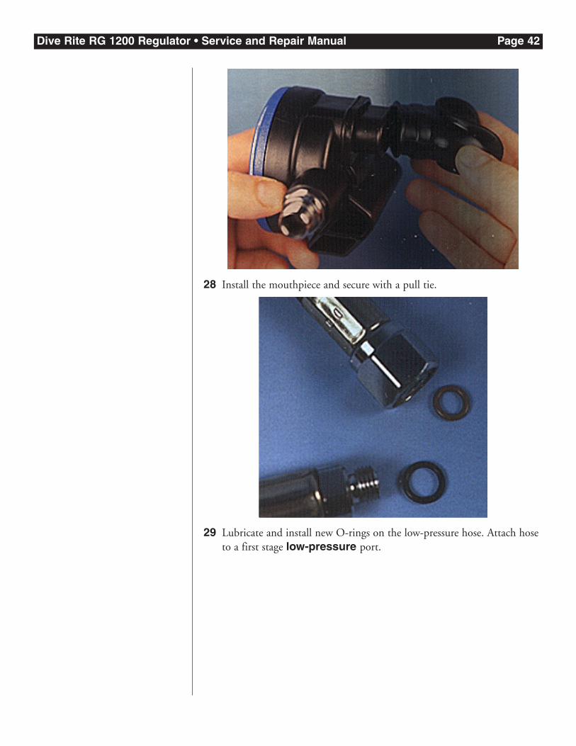
28 Install the mouthpiece and secure with a pull tie.
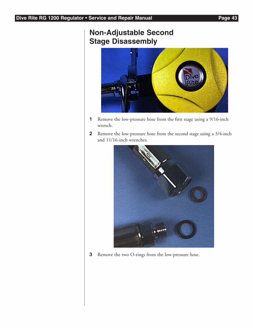
29 Lubricate and install new O-rings on the low-pressure hose. Attach hoseto a first stage low-pressure port.
Dive Rite RG 1200 Regulator • Service and Repair Manual Page 43
Non-Adjustable Second Stage Disassembly
1 Remove the low-pressure hose from the first stage using a 9/16-inchwrench.
2 Remove the low-pressure hose from the second stage using a 3/4-inchand 11/16-inch wrenches.
3 Remove the two O-rings from the low-pressure hose.
Dive Rite RG 1200 Regulator • Service and Repair Manual Page 44
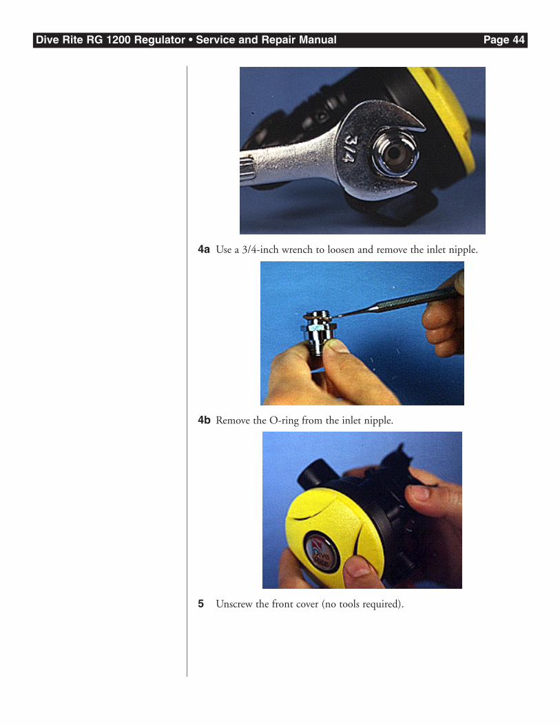
4a Use a 3/4-inch wrench to loosen and remove the inlet nipple.
4b Remove the O-ring from the inlet nipple.
5 Unscrew the front cover (no tools required).
Dive Rite RG 1200 Regulator • Service and Repair Manual Page 45
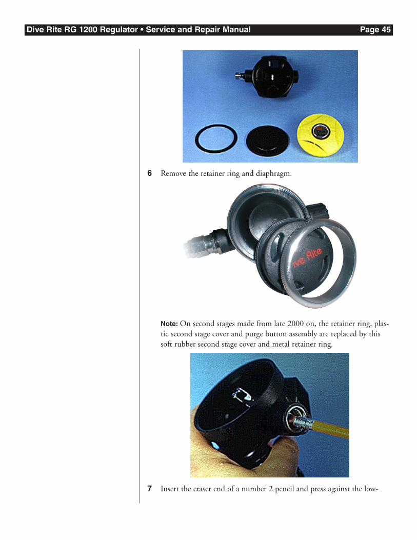
6 Remove the retainer ring and diaphragm.
Note: On second stages made from late 2000 on, the retainer ring, plas-tic second stage cover and purge button assembly are replaced by thissoft rubber second stage cover and metal retainer ring.
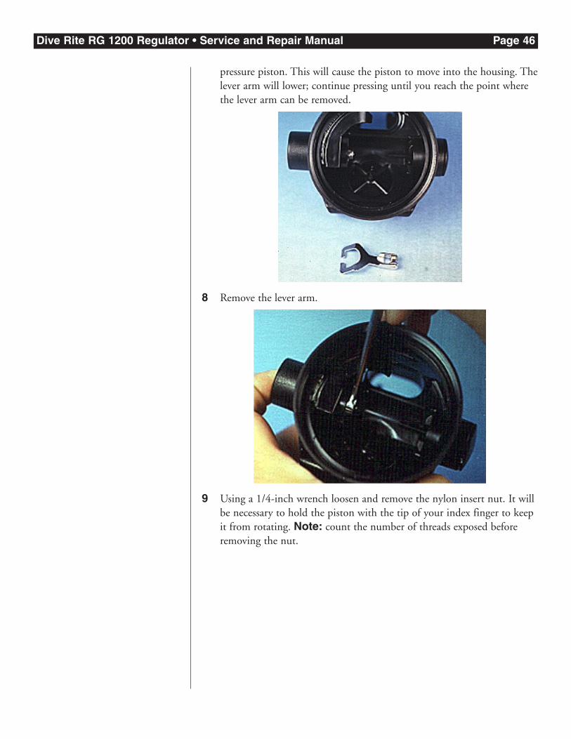
7 Insert the eraser end of a number 2 pencil and press against the low-
Dive Rite RG 1200 Regulator • Service and Repair Manual Page 46
pressure piston. This will cause the piston to move into the housing. Thelever arm will lower; continue pressing until you reach the point wherethe lever arm can be removed.
8 Remove the lever arm.
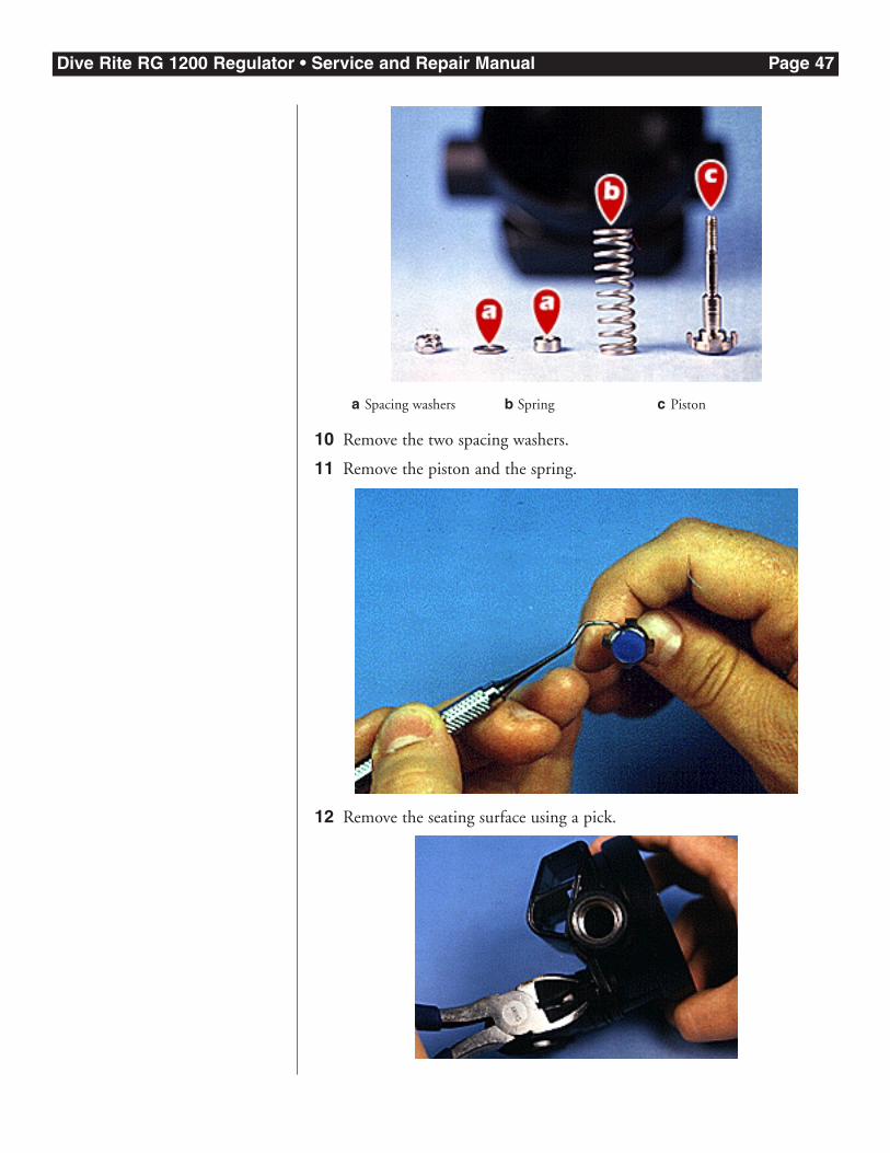
9 Using a 1/4-inch wrench loosen and remove the nylon insert nut. It willbe necessary to hold the piston with the tip of your index finger to keepit from rotating. Note: count the number of threads exposed beforeremoving the nut.
Dive Rite RG 1200 Regulator • Service and Repair Manual Page 47
10 Remove the two spacing washers.
11 Remove the piston and the spring.
12 Remove the seating surface using a pick.
a Spacing washers b Spring c Piston
Dive Rite RG 1200 Regulator • Service and Repair Manual Page 48
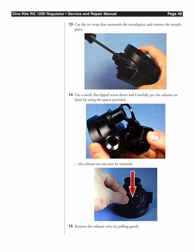
13 Cut the tie wrap that surrounds the mouthpiece and remove the mouth-piece.
14 Use a small, flat-tipped screw driver and Carefully pry the exhaust teeloose by using the spaces provided.
…the exhaust tee can now be removed.
15 Remove the exhaust valve by pulling gently.
Dive Rite RG 1200 Regulator • Service and Repair Manual Page 49
The second stage is now ready for parts replacement, cleaning, reassemblyand adjustment.
Servicing Disassembled Second Stage PartsDive Rite makes available all the items you should replace as part of a nor-mal second-stage overhaul in kit form. This kit contains:
1 From the collection of disassembled first stage parts, remove and packagethose items that will be replaced by items from the service kit.
2 Thoroughly clean the remaining items in a solution compatible withNitrox service.
3 When lubricating O-rings, use only Nitrox-compatible lubricants, suchas Techno Lube.
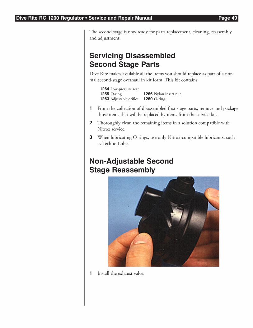
Non-Adjustable Second Stage Reassembly
1 Install the exhaust valve.
1264 Low-pressure seat1255 O-ring1263 Adjustable orifice
1266 Nylon insert nut1260 O-ring
Dive Rite RG 1200 Regulator • Service and Repair Manual Page 50
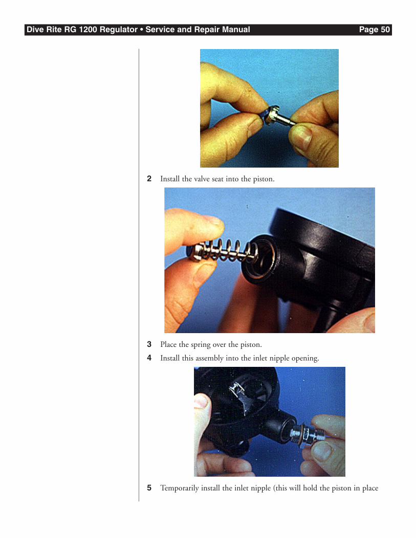
2 Install the valve seat into the piston.
3 Place the spring over the piston.
4 Install this assembly into the inlet nipple opening.
5 Temporarily install the inlet nipple (this will hold the piston in place
Dive Rite RG 1200 Regulator • Service and Repair Manual Page 51
and make the next step easier).
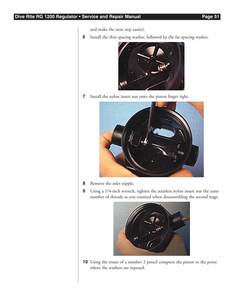
6 Install the thin spacing washer, followed by the fat spacing washer.
7 Install the nylon insert nut onto the piston finger tight.
8 Remove the inlet nipple.
9 Using a 1/4-inch wrench, tighten the stainless nylon insert nut the samenumber of threads as you counted when disassembling the second stage.
10 Using the eraser of a number 2 pencil compress the piston to the pointwhere the washers are exposed.
Dive Rite RG 1200 Regulator • Service and Repair Manual Page 52
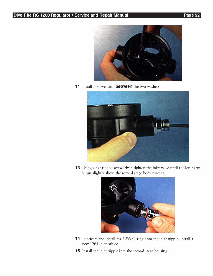
11 Install the lever arm between the two washers.
13 Using a flat-tipped screwdriver, tighten the inlet valve until the lever armis just slightly above the second stage body threads.
14 Lubricate and install the 1255 O-ring onto the inlet nipple. Install anew 1263 inlet orifice.
15 Install the inlet nipple into the second stage housing.
Dive Rite RG 1200 Regulator • Service and Repair Manual Page 53
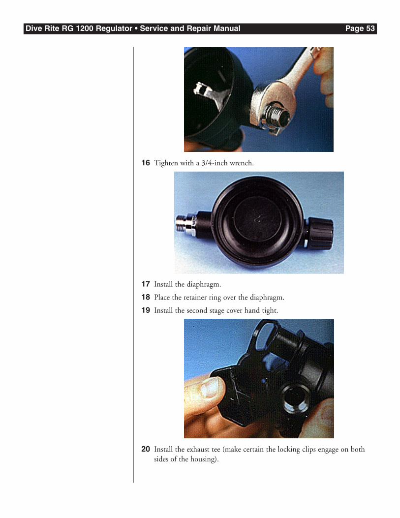
16 Tighten with a 3/4-inch wrench.
17 Install the diaphragm.
18 Place the retainer ring over the diaphragm.
19 Install the second stage cover hand tight.
20 Install the exhaust tee (make certain the locking clips engage on bothsides of the housing).
Dive Rite RG 1200 Regulator • Service and Repair Manual Page 54
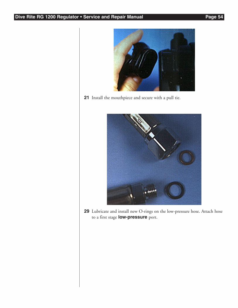
21 Install the mouthpiece and secure with a pull tie.
29 Lubricate and install new O-rings on the low-pressure hose. Attach hoseto a first stage low-pressure port.
Dive Rite RG 1200 Regulator • Service and Repair Manual Page 55
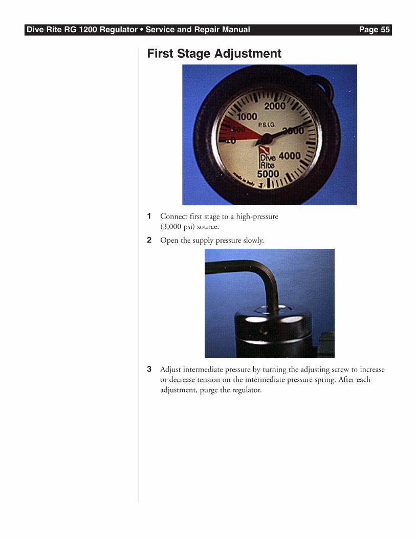
First Stage Adjustment
1 Connect first stage to a high-pressure (3,000 psi) source.
2 Open the supply pressure slowly.
3 Adjust intermediate pressure by turning the adjusting screw to increaseor decrease tension on the intermediate pressure spring. After eachadjustment, purge the regulator.
Dive Rite RG 1200 Regulator • Service and Repair Manual Page 56
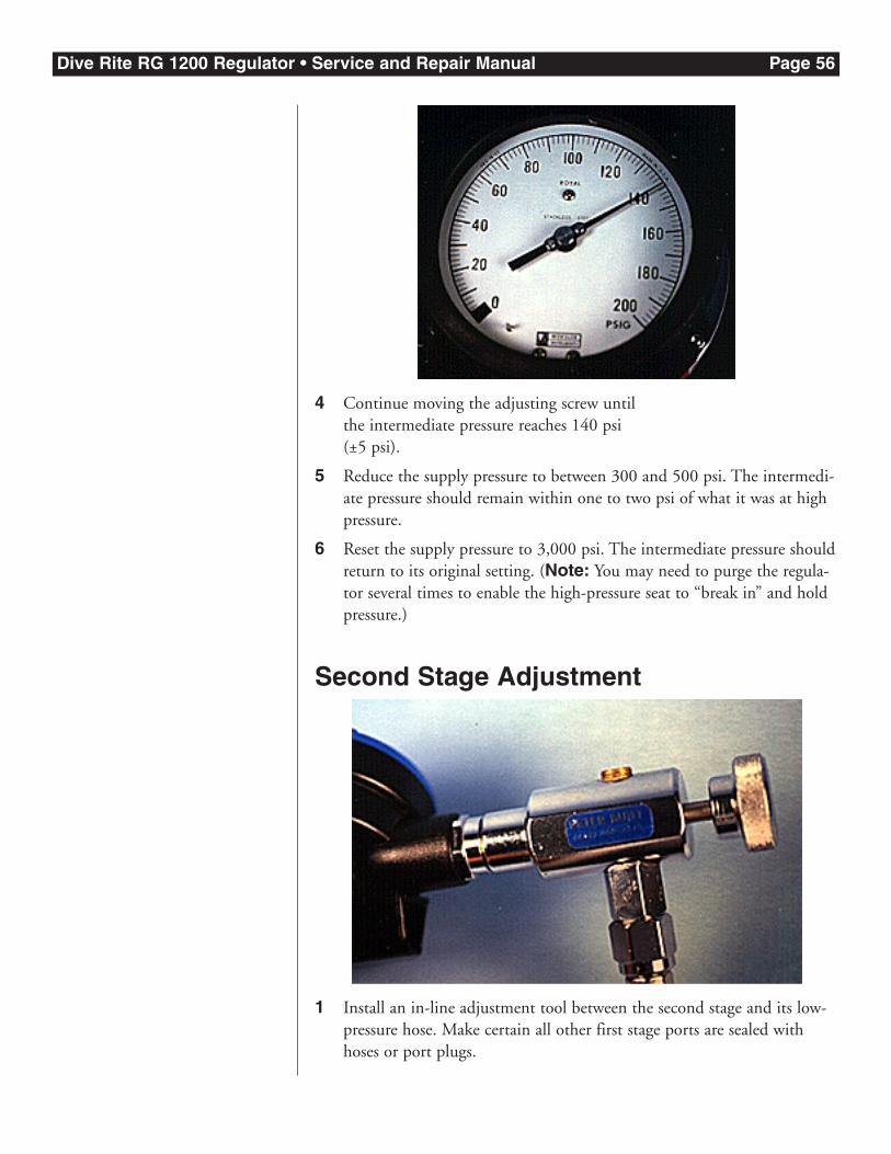
4 Continue moving the adjusting screw until the intermediate pressure reaches 140 psi (±5 psi).
5 Reduce the supply pressure to between 300 and 500 psi. The intermedi-ate pressure should remain within one to two psi of what it was at highpressure.
6 Reset the supply pressure to 3,000 psi. The intermediate pressure shouldreturn to its original setting. (Note: You may need to purge the regula-tor several times to enable the high-pressure seat to “break in” and holdpressure.)
Second Stage Adjustment
1 Install an in-line adjustment tool between the second stage and its low-pressure hose. Make certain all other first stage ports are sealed withhoses or port plugs.
Dive Rite RG 1200 Regulator • Service and Repair Manual Page 57
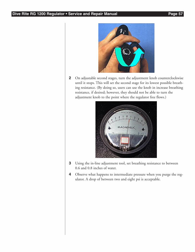
2 On adjustable second stages, turn the adjustment knob counterclockwiseuntil it stops. This will set the second stage for its lowest possible breath-ing resistance. (By doing so, users can use the knob in increase breathingresistance, if desired; however, they should not be able to turn theadjustment knob to the point where the regulator free flows.)
3 Using the in-line adjustment tool, set breathing resistance to between0.6 and 0.8 inches of water.
4 Observe what happens to intermediate pressure when you purge the reg-ulator. A drop of between two and eight psi is acceptable.
Dive Rite RG 1200 Regulator • Service and Repair Manual Page 58
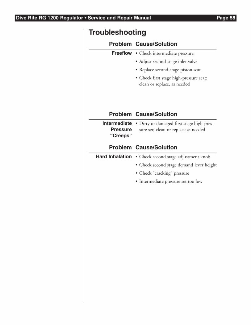
Troubleshooting
Freeflow • Check intermediate pressure
• Adjust second-stage inlet valve
• Replace second-stage piston seat
• Check first stage high-pressure seat;clean or replace, as needed
Problem Cause/Solution
IntermediatePressure“Creeps”
• Dirty or damaged first stage high-pres-sure set; clean or replace as needed
Problem Cause/Solution
Hard Inhalation • Check second stage adjustment knob
• Check second stage demand lever height
• Check “cracking” pressure
• Intermediate pressure set too low
Problem Cause/Solution
Dive Rite RG 1200 Regulator • Service and Repair Manual Page 59
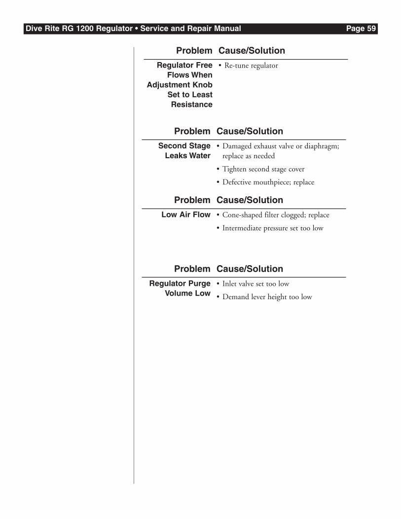
Low Air Flow • Cone-shaped filter clogged; replace
• Intermediate pressure set too low
Problem Cause/Solution
Regulator PurgeVolume Low
• Inlet valve set too low
• Demand lever height too low
Problem Cause/Solution
Regulator FreeFlows When
Adjustment KnobSet to LeastResistance
• Re-tune regulator
Problem Cause/Solution
Second StageLeaks Water
• Damaged exhaust valve or diaphragm;replace as needed
• Tighten second stage cover
• Defective mouthpiece; replace
Problem Cause/Solution
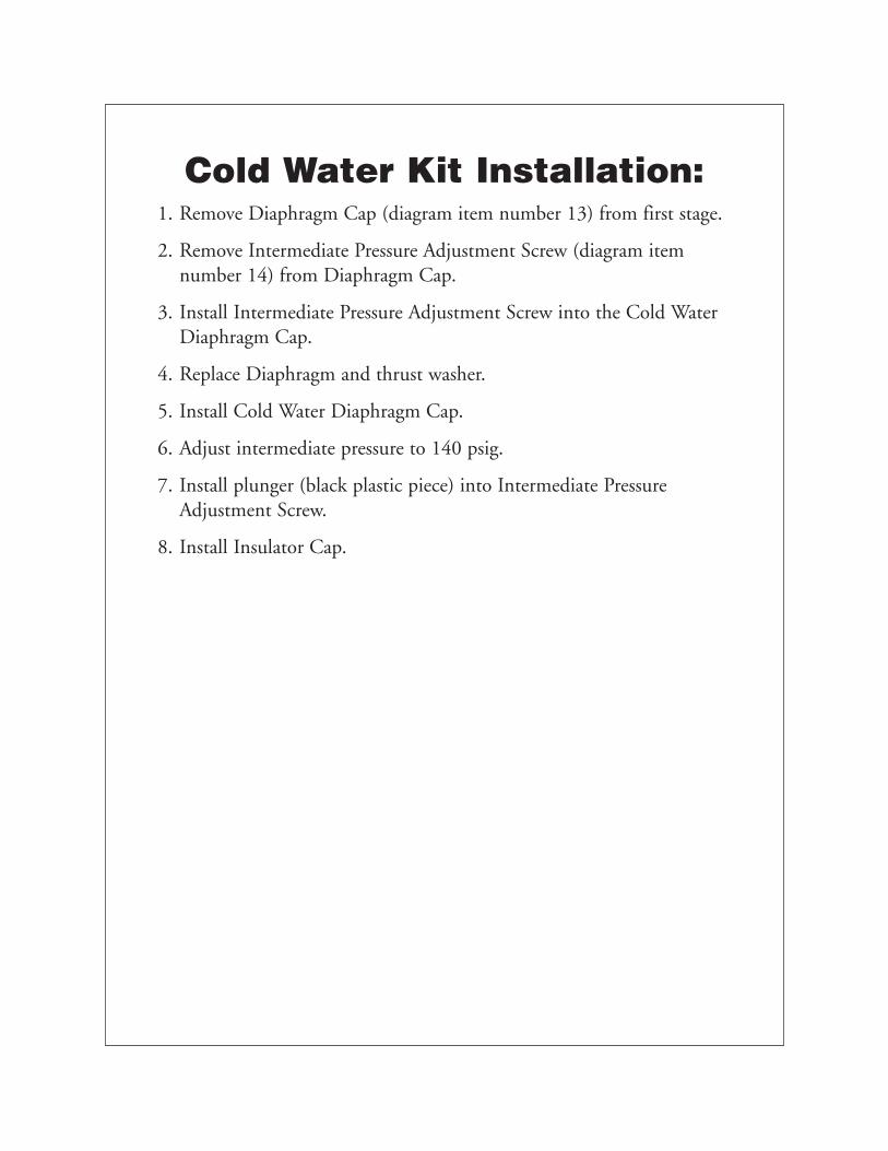
Cold Water Kit Installation:1. Remove Diaphragm Cap (diagram item number 13) from first stage.
2. Remove Intermediate Pressure Adjustment Screw (diagram itemnumber 14) from Diaphragm Cap.
3. Install Intermediate Pressure Adjustment Screw into the Cold WaterDiaphragm Cap.
4. Replace Diaphragm and thrust washer.
5. Install Cold Water Diaphragm Cap.
6. Adjust intermediate pressure to 140 psig.
7. Install plunger (black plastic piece) into Intermediate PressureAdjustment Screw.
8. Install Insulator Cap.
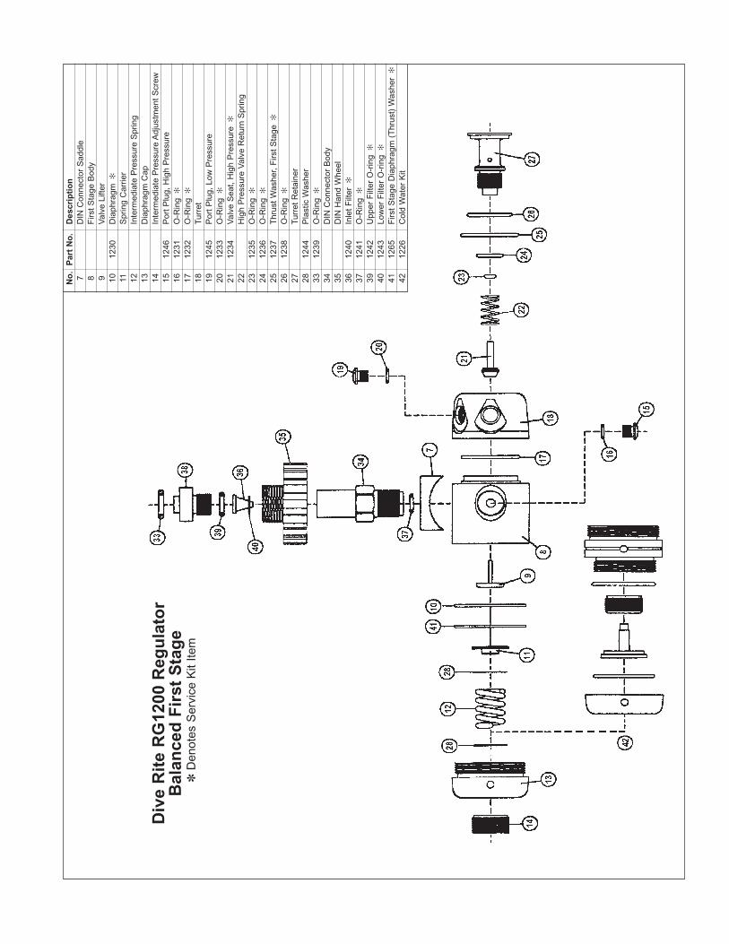
No
.P
art
No
.D
escr
ipti
on
7D
IN C
onne
ctor
Sad
dle
8F
irst S
tage
Bod
y9
Val
ve L
ifter
1012
30D
iaph
ragm
✻
11S
prin
g C
arrie
r12
Inte
rmed
iate
Pre
ssur
e S
prin
g13
Dia
phra
gm C
ap14
Inte
rmed
iate
Pre
ssur
e A
djus
tmen
t Scr
ew15
1246
Por
t Plu
g, H
igh
Pre
ssur
e16
1231
O-R
ing
✻
1712
32O
-Rin
g✻
18Tu
rret
1912
45P
ort P
lug,
Low
Pre
ssur
e20
1233
O-R
ing
✻
2112
34V
alve
Sea
t, H
igh
Pre
ssur
e✻
22H
igh
Pre
ssur
e V
alve
Ret
urn
Spr
ing
2312
35O
-Rin
g✻
2412
36O
-Rin
g✻
2512
37T
hrus
t Was
her,
Firs
t Sta
ge✻
2612
38O
-Rin
g✻
27Tu
rret
Ret
aine
r28
1244
Pla
stic
Was
her
3312
39O
-Rin
g✻
34D
IN C
onne
ctor
Bod
y35
DIN
Han
d W
heel
3612
40In
let F
ilter
✻
3712
41O
-Rin
g✻
3912
42U
pper
Filt
er O
-rin
g✻
4012
43Lo
wer
Filt
er O
-rin
g✻
4112
65F
irst S
tage
Dia
phra
gm (
Thr
ust)
Was
her
✻
4212
26C
old
Wat
er K
it
Div
e R
ite
RG
1200
Reg
ula
tor
Bal
ance
d F
irst
Sta
ge
✽D
enot
es S
ervi
ce K
it Ite
m
No
.P
art
No
.D
escr
ipti
on
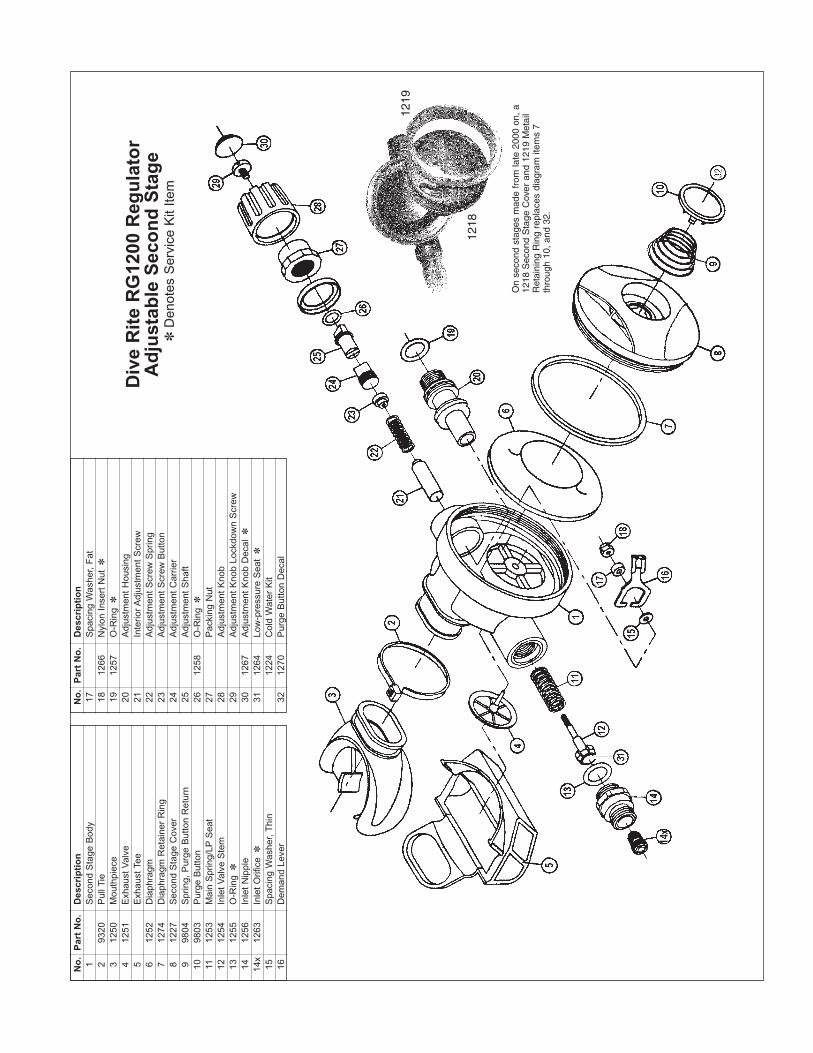
1S
econ
d S
tage
Bod
y2
9320
Pul
l Tie
312
50M
outh
piec
e4
1251
Exh
aust
Val
ve5
Exh
aust
Tee
612
52D
iaph
ragm
712
74D
iaph
ragm
Ret
aine
r R
ing
812
27S
econ
d S
tage
Cov
er9
9804
Spr
ing,
Pur
ge B
utto
n R
etur
n10
9803
Pur
ge B
utto
n11
1253
Mai
n S
prin
g/LP
Sea
t12
1254
Inle
t Val
ve S
tem
1312
55O
-Rin
g✽
1412
56In
let N
ippl
e14
x12
63In
let O
rific
e✽
15S
paci
ng W
ashe
r, T
hin
16D
eman
d Le
ver
No
.P
art
No
.D
escr
ipti
on
17S
paci
ng W
ashe
r, F
at18
1266
Nyl
on In
sert
Nut
✽
1912
57O
-Rin
g✽
20A
djus
tmen
t Hou
sing
21In
terio
r Adj
ustm
ent S
crew
22A
djus
tmen
t Scr
ew S
prin
g23
Adj
ustm
ent S
crew
But
ton
24A
djus
tmen
t Car
rier
25A
djus
tmen
t Sha
ft26
1258
O-R
ing
✽
27P
acki
ng N
ut28
Adj
ustm
ent K
nob
29A
djus
tmen
t Kno
b Lo
ckdo
wn
Scr
ew30
1267
Adj
ustm
ent K
nob
Dec
al✽
3112
64Lo
w-p
ress
ure
Sea
t✽
1224
Col
d W
ater
Kit
3212
70P
urge
But
ton
Dec
al
Div
e R
ite
RG
1200
Reg
ula
tor
Ad
just
able
Sec
on
d S
tag
e✽
Den
otes
Ser
vice
Kit
Item
1218
1219
On
seco
nd s
tage
s m
ade
from
late
200
0 on
, a
1218
Sec
ond
Sta
ge C
over
and
121
9 M
etai
lR
etai
ning
Rin
g re
plac
es d
iagr
am it
ems
7th
roug
h 10
, an
d 32
.
No
.P
art
No
.D
escr
ipti
on
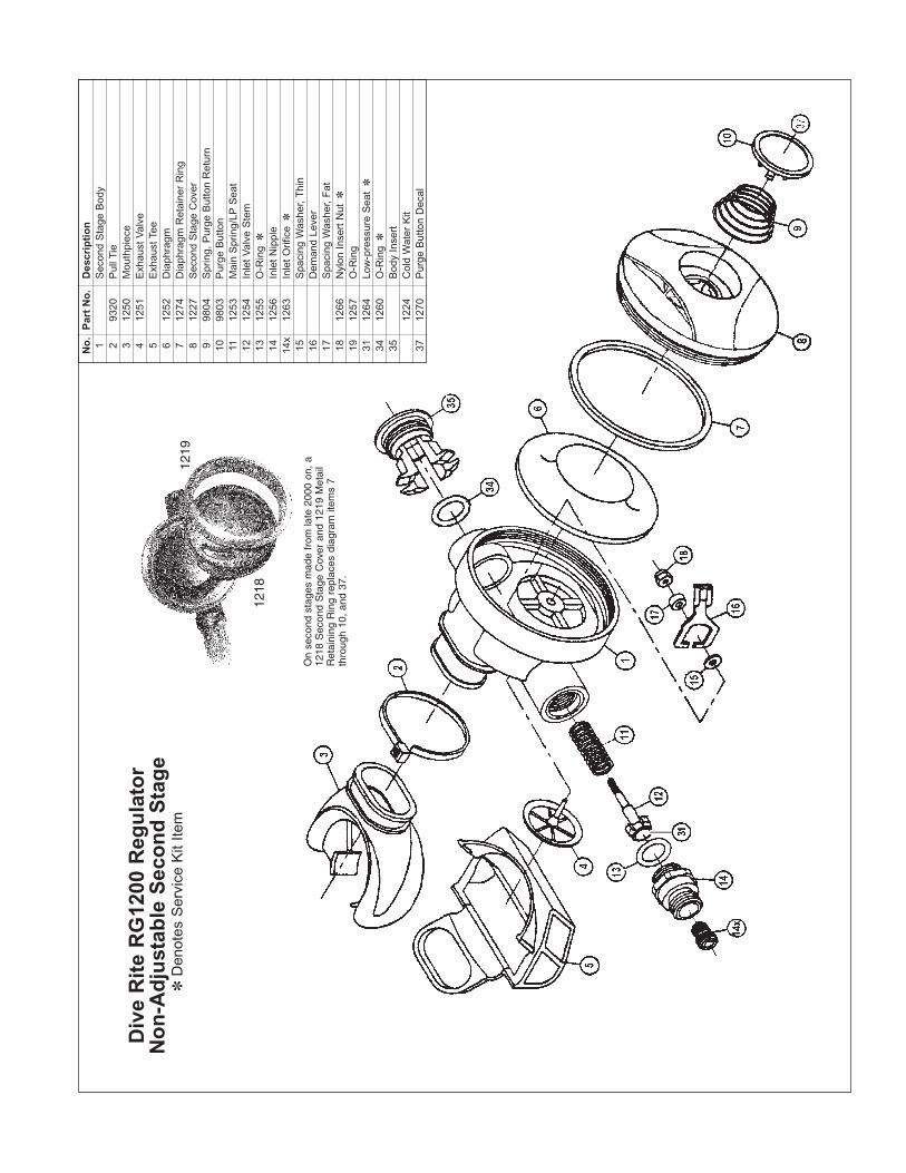
1S
econ
d S
tage
Bod
y2
9320
Pul
l Tie
312
50M
outh
piec
e4
1251
Exh
aust
Val
ve5
Exh
aust
Tee
612
52D
iaph
ragm
712
74D
iaph
ragm
Ret
aine
r R
ing
812
27S
econ
d S
tage
Cov
er9
9804
Spr
ing,
Pur
ge B
utto
n R
etur
n10
9803
Pur
ge B
utto
n11
1253
Mai
n S
prin
g/LP
Sea
t12
1254
Inle
t Val
ve S
tem
1312
55O
-Rin
g✽
1412
56In
let N
ippl
e14
x12
63In
let O
rific
e✽
15S
paci
ng W
ashe
r, T
hin
16D
eman
d Le
ver
17S
paci
ng W
ashe
r, F
at18
1266
Nyl
on In
sert
Nut
✽
1912
57O
-Rin
g31
1264
Low
-pre
ssur
e S
eat
✽
3412
60O
-Rin
g✽
35B
ody
Inse
rt12
24C
old
Wat
er K
it37
1270
Pur
ge B
utto
n D
ecal
Div
e R
ite
RG
1200
Reg
ula
tor
No
n-A
dju
stab
le S
eco
nd
Sta
ge
✽D
enot
es S
ervi
ce K
it Ite
m
1218
1219
On
seco
nd s
tage
s m
ade
from
late
200
0 on
, a
1218
Sec
ond
Sta
ge C
over
and
121
9 M
etai
lR
etai
ning
Rin
g re
plac
es d
iagr
am it
ems
7th
roug
h 10
, an
d 37
.


