RG - FRG/2MCC - RG - FRG/2MCS SECTION CHAPTER 5 1 (UNI 9002-5) • Acier INOX 430 F (UNI EN 10088)...
12
1 FRG/2MCC-S - RG/2MCC-S DN 15 - DN 20 - DN 25 CHAPTER 1.0 SECTION 5 Madas Technical Manual REV. 1 of 18 th April 2018 P 1 max 3 - 5 bar RG - FRG/2MCC - RG - FRG/2MCS (DN 15 ÷ DN 25) FRG/2MCC RG/2MCC FRG/2MCS RG/2MCS REGOLATORI DI PRESSIONE PER GAS MONOSTADIO CON OTTURATORE COMPENSATO SINGLE STAGE GAS PRESSURE REGULATOR WITH COMPENSED OBTURATOR RÉGULATEURS DE PRESSION POUR GAZ MONOSTADE AVEC OBTURATEUR COMPENSÉ REGULADORES DE PRESIÓN PARA GAS MONOETAPA CON OBTURATOR COMPENSADO • Descrizione / Description Description / Descripción: Riduttore di pressione per gas con otturatore compensato ad azione diretta. Direct-operated gas pressure regulator with compensated obturator. Réducteur de pression pour gaz avec obturateur compensé à action directe. Reductor de presión para gas con obturador compensado de acción directa. • Norma di riferimento / Reference standard Norme de référence / Patrón de referencia: EN 88-2 - EN 334 EN 88-2 - EN 334 EN 88-2 - EN 334 EN 88-2 - EN 334 • In conformità a / in conformity with / conforme a / conforme: Direttiva PED 2014/68/UE (ex 97/23/CE) Direttiva Gas 2009/142/CE fino al 20/04/2018 Regolamento (UE) 2016/426 dal 21/04/2018 Direttiva ATEX 2014/34/UE (ex 94/9/CE) 2014/68/EU PED Directive (ex 97/23/EC) 2009/142/EC Gas Directive until 20/04/2018 Regulation (EU) 2016/426 from 21/04/2018 2014/34/EU ATEX Directive (ex 94/9/EC) Directive PED 2014/68/UE (ex 97/23/CE) Directive Gaz 2009/142/CE jusqu'au 20/04/2018 Règlement (UE) 2016/426 du 21/04/2018 Directive ATEX 2014/34/UE (ex 94/9/CE) Directiva PED 2014/68/UE (ex 97/23/CE) Directiva Gas 2009/142/CE hasta el 20/04/2018 Reglamento (UE) 2016/426 del 21/04/2018 Directiva ATEX 2014/34/UE (ex 94/9/CE) • Atex Zone 1, 21, 2, 22 1, 21, 2, 22 1, 21, 2, 22 1, 21, 2, 22 • Può essere dotato dei seguenti dispositivi di sicurezza e accessori: • It can be equipped with the following safety devices and accessories: • Il peut être fourni avec les suivants dispositifs de sécurité et accessoires: • Puede ser equipado con los siguientes dispositivos de seguridad y accesorios: VALVOLA DI SFIORO: scarica all’esterno piccole portate di gas nel caso si verifichino sovrappressioni a valle del regolatore. Tale scarico è convogliabile all’esterno nel caso di installazioni in ambienti con scarsa ventilazione PRESA DI PRESSIONE IN USCITA. RELIEF VALVE: it vents outside small quantity of gas in case there are downstream regulator overpressure. That exhaust it is convoyed outside in case of installation in environment with bad ventilation OUTLET PRESSURE TEST POINT. VANNE DE DÉCHARGE: elle évacue vers l’extérieur de petites quantités de gaz s’il y a des surpressions en aval du régulateur. Ce gaz est évacué vers l’extérieur dans le cas d’installations dans des lieux peu ventilés PRISE DE PRESSION EN SORTIE. VÁLVULA DE ALIVIO: descarga hacia el exterior pequeños caudales de gas en caso de verificarse exceso de presión en posición sucesiva al regulador. Dicha descarga puede ser conducida al exterior en caso de tratarse de instalaciones en ambientes con escasa ventilación TOMA DE PRESIÓN EN SALIDA. 0051 0497 II 2G - II 2D MADAS-03
Transcript of RG - FRG/2MCC - RG - FRG/2MCS SECTION CHAPTER 5 1 (UNI 9002-5) • Acier INOX 430 F (UNI EN 10088)...

1FRG/2MCC-S - RG/2MCC-SDN 15 - DN 20 - DN 25
Chapter
1.0SeCtion
5
Madas Technical ManualREV. 1 of 18th April 2018
P1 max 3 - 5 bar
RG - FRG/2MCC - RG - FRG/2MCS(DN 15 ÷ DN 25)
FRG/2MCC RG/2MCC
FRG/2MCSRG/2MCS
REGOLATORI DI PRESSIONE PER GAS MONOSTADIO CON OTTURATORE COMPENSATOSINGLE STAGE GAS PRESSURE REGULATOR WITH COMPENSED OBTURATOR
RÉGULATEURS DE PRESSION POUR GAZ MONOSTADE AVEC OBTURATEUR COMPENSÉREGULADORES DE PRESIÓN PARA GAS MONOETAPA CON OBTURATOR COMPENSADO
• Descrizione / Description Description / Descripción:
Riduttore di pressione per gas con otturatore compensato ad azione
diretta.
Direct-operated gas pressure regulator with compensated obturator.
Réducteur de pression pour gaz avec
obturateur compensé à action directe.
Reductor de presión para gas con obturador compensado de acción
directa.
• Norma di riferimento / Reference standard Norme de référence / Patrón de referencia: EN 88-2 - EN 334 EN 88-2 - EN 334 EN 88-2 - EN 334 EN 88-2 - EN 334
• In conformità a / in conformity with / conforme a / conforme:
Direttiva PED 2014/68/UE(ex 97/23/CE)
Direttiva Gas 2009/142/CE fino al 20/04/2018
Regolamento (UE) 2016/426 dal 21/04/2018
Direttiva ATEX 2014/34/UE(ex 94/9/CE)
2014/68/EU PED Directive(ex 97/23/EC)
2009/142/EC Gas Directive until 20/04/2018
Regulation (EU) 2016/426 from 21/04/2018
2014/34/EU ATEX Directive(ex 94/9/EC)
Directive PED 2014/68/UE(ex 97/23/CE)
Directive Gaz 2009/142/CE jusqu'au 20/04/2018
Règlement (UE) 2016/426 du 21/04/2018
Directive ATEX 2014/34/UE(ex 94/9/CE)
Directiva PED 2014/68/UE(ex 97/23/CE)
Directiva Gas 2009/142/CE hasta el 20/04/2018
Reglamento (UE) 2016/426 del 21/04/2018
Directiva ATEX 2014/34/UE (ex 94/9/CE)
• Atex Zone 1, 21, 2, 22 1, 21, 2, 22 1, 21, 2, 22 1, 21, 2, 22
• Può essere dotato dei seguenti dispositivi di sicurezza e accessori:
• It can be equipped with the following safety devices and accessories:
• Il peut être fourni avec les suivants dispositifs de sécurité et accessoires:
• Puede ser equipado con los siguientes dispositivos de seguridad y accesorios:
VALVOLA DI SFIORO:
scarica all’esterno piccole portate di gas nel caso si verifichino sovrappressioni a valle del regolatore.
Tale scarico è convogliabile all’esterno nel caso di installazioni in ambienti con scarsa ventilazione
PRESA DI PRESSIONE IN USCITA.
RELIEF VALVE:
it vents outside small quantity of gas in case there are downstream regulator overpressure.
That exhaust it is convoyed outside in case of installation in environment with bad ventilation
OUTLET PRESSURE TEST POINT.
VANNE DE DÉCHARGE:
elle évacue vers l’extérieur de petites quantités de gaz s’il y a des surpressions en aval du régulateur.
Ce gaz est évacué vers l’extérieur dans le cas d’installations dans des lieux peu ventilés
PRISE DE PRESSION EN SORTIE.
VÁLVULA DE ALIVIO:
descarga hacia el exterior pequeños caudales de gas en caso de verificarse exceso de presión en posición sucesiva al regulador. Dicha descarga puede ser conducida al exterior en caso de tratarse de instalaciones en ambientes con escasa ventilación
TOMA DE PRESIÓN EN SALIDA.
00510497
II 2G - II 2DMADAS-03

2 FRG/2MCC-S - RG/2MCC-SDN 15 - DN 20 - DN 25
Chapter
1.0SeCtion
5 P1 max 3 - 5 bar
RG - FRG/2MCC - RG - FRG/2MCS(DN 15 ÷ DN 25)
Madas Technical ManualREV. 1 of 18th April 2018
• Impiego / Use / Emploi / Utilizaciòn: gas non aggressivi delle3 famiglie (gas secchi)
not aggressive gases of the 3 families (dry gases)
gaz non agressifs des 3 familles(gaz secs)
gases de las 3 familias(secos y no agresivos)
• Attacchi filettati Rp / Threaded connections Rp Fixations filetees Rp / Conexiones roscadas Rp:
DN 15 ÷ DN 25secondo EN 10226
SU RICHIESTA ATTACCHI NPT
DN 15 ÷ DN 25according to EN 10226
ON REQUEST NPTCONNECTIONS
DN 15 ÷ DN 25selon EN 10226SUR DEMANDE FIXATIONS NPT
DN 15 ÷ DN 25según EN 10226
A PETICIÓN CONEXIONES NPT
• Attacchi flangiati PN 16 / Flanged connections PN 16 Conexiones de brida PN 16 / Conexiones de brida PN 16:
DN 25secondo ISO 7005
SU RICHIESTA ATTACCHI ANSI 150
DN 25according to ISO 7005
ON REQUEST ANSI 150CONNECTIONS
DN 25selon ISO 7005
SUR DEMANDE FIXATIONS ANSI 150
DN 25según ISO 7005
A PETICIÓN CONEXIONES ANSI 150
• Pressione min esercizio / Min. working pressure / Pression minimale en exercice / Min. presion ejercicio: 0,5 bar
• Pressione max esercizio / Max. working pressure Pression maximale en exercice / Max. presion ejercicio: 3 - 5 bar
• Temperatura ambiente / Environment temperature Température ambiante / Temperatura ambiente: -20 ÷ +60 °C
• Temperatura superficiale max / Max superficial temperature Température ambiante / Temperatura superficial máxima: +60 °C
• Classe accuratezza P2 / P2 accuracy class Classe de précision P2 / Clase precisión P2: AC 10
• Classe pressione di chiusura / Closing pressure class Pression de fermeture / Clase presión de cierre: SG 30 (P2>200 mbar SG 20)
• Resistenza meccanica / Mechanical strength Résistance mécanique / Resistencia mecánica:
Gruppo 2(secondo EN 13611:2007)
Group 2(according to EN 13611:2007)
Groupe 2(selon EN 13611:2007)
Grupo 2(según EN 13611:2007)
• Campo pressione intervento / Trip pressure range Gamme intervention pression / Campo presión intervención: • vedere tabella molle • see springs table • voir tableau des ressorts • véase tabla muelle
• Tempo di chiusura blocco / Shut off closure time Temps de fermeture arrêt / Tiempo cierre bloqueo: < 1 s
• Valvola di sfioro / Relief valve Valve de sécurité / Válvula de alivio: • testata secondo EN 334 • tested according to EN 334 • testée selon EN 334 • testada en conformidad con
EN 334
• Connessione dello sfiato: / Vent connection Connecteur d’évacuation / Conexión del respiradero: G 1/4”
• Filtraggio / Filtration / Filtrage / Filtración: 50 µm(su richiesta altre qualità di filtraggio)
50 µm(on request other filtration qualities)
50 µm(sur demande autres qualités de filtrage)
50 µm(a petición otras clases de filtración)
• Classe di filtrazione / Filtration class Classe de filtrage / Clase de filtración:
G 2(secondo EN 779)
G 2(according to EN 779)
G 2(selon EN 779)
G 2(según EN 779)
• Materiali / Materials / Matériels / Materiales:
• Alluminio pressofuso
(UNI EN 1706)
• Ottone OT-58
(UNI EN 12164)
• Alluminio 11S
(UNI 9002-5)
• Acciaio INOX 430 F
(UNI EN 10088)
• Gomma antiolio NBR
(UNI 7702)
• Nylon 30% fibra di vetro
(UNI EN ISO 11667)
• Viledon
• Die-cast aluminium
(UNI EN 1706)
• OT-58 brass
(UNI EN 12164)
• 11S aluminium
(UNI 9002-5)
• F stainless steel
(UNI EN 10088)
• NBR rubber
(UNI 7702)
• Nylon 30% glass fibre
(UNI EN ISO 11667)
• Viledon
• Alluminium fondé dans la masse
(UNI EN 1706)
• Laiton OT-58
(UNI EN 12164)
• Alluminium 11S
(UNI 9002-5)
• Acier INOX 430 F
(UNI EN 10088)
• Caoutchou anti-huile NBR
• (UNI 7702)
• Nylon 30% fibre de verre
(UNI EN ISO 11667)
• Viledon
• Aluminio inyectado a presiòn
(UNI EN 1706)
• Latòn OT-58
(UNI EN 12164)
• Aluminio 11S
(UNI 9002-5)
• Acero galvanizado
(UNI EN 10088)
• Goma antiaceite NBR
(UNI 7702)
• Nylon 30% fibra de vidrio
(UNI EN ISO 11667)
• Viledon

3FRG/2MCC-S - RG/2MCC-SDN 15 - DN 20 - DN 25
Chapter
1.0SeCtion
5
Madas Technical ManualREV. 1 of 18th April 2018
P1 max 3 - 5 bar
RG - FRG/2MCC - RG - FRG/2MCS(DN 15 ÷ DN 25)
TABELLA COSTRUZIONE RG-FRG MODELLI 2MCSTABLE CONSTRUCTION RG-FRG 2MCS MODELS
MODELLOMODEL
ATTACCOCONNECTION
VERSIONEVERSION
MOLLA P2 N°
P2 SPRING NO.
MOLLA OPSO N°
OPSO SPRING NO.
MOLLA UPSON°
UPSO SPRINGNO.
MOLLA SFIORON°
RELIEF SPRINGNO.
FCS 03 2 X X 2Con Filtro
with FilterDn 15 P1= 0,5 ÷ 3 bar 20 ÷ 30
mbar
senza OPSO
without OPSO
senza UPSO
without UPSO
10 ÷ 60mbar
FCS 04 0000 4 X X XCon Filtro
with FilterDn 25 P1= 0,5 ÷ 5 bar 60 ÷ 90
mbar
senza OPSO
without OPSO
senza UPSO
without UPSO
senza sfioro
without relief
In tabella sono riportati alcuni esempi per illustrare come è possibile combinare tra di loro le molle di taratura.Per i modelli “2MCS”:• non possono essere presenti OPSO e UPSO (quindi molle n°2 e n°3 sempre indicate con “X”);• si può omettere lo sfioro contrassegnando con una “X” il campo molla corrispondente (n° 4), in tal caso il prezzo non subisce variazioni;Non tutte le combinazioni sono possibili, devono essere funzionalmente compatibili. Si consiglia di contattare il nostro ufficio commerciale per la conferma della fattibilità.
Table shows some examples to illustrate how it is possible to combine the setting springs. For “2MCS” models: • OPSO UPSO are not present (then springs No. 2 and No. 3 always marked with “X”); • you may omit the relief valve marking with an “X” the corresponding spring range (n° 4), in this case the price will not change; Not all combinations are possible, they must be functionally compatible. It is advisable to contact our sales department for feasibility confirmation.
TABELLA COSTRUZIONE RG-FRG MODELLI 2MCCTABLE CONSTRUCTION RG-FRG 2MCC MODELS
MODELLOMODEL
ATTACCOCONNECTION
VERSIONEVERSION
MOLLA P2 N°
P2 SPRING NO.
MOLLA OPSO N°
OPSO SPRING NO.
MOLLA UPSON°
UPSO SPRINGNO.
MOLLA SFIORON°
RELIEF SPRINGNO.
FCC 03 1 X X 2moDello CompaCt Con Filtro
CompaCt moDel with FilterDn 15 P1= 0,5 ÷ 3 bar 10 ÷ 25
mbar
senza OPSO
without OPSO
senza UPSO
without UPSO
10 ÷ 60mbar
rCC 04 0000 5 X X XmoDello CompaCt Senza Filtro
CompaCt moDel without FilterDN 25 P1= 0,5 ÷ 5 bar 110 ÷ 200
mbar
senza OPSO
without OPSO
senza UPSO
without UPSO
senza sfioro
without relief
In tabella sono riportati alcuni esempi per illustrare come è possibile combinare tra di loro le molle di taratura.Per i modelli compact “2MCC”:• gli attacchi disponibili sono DN 15 - DN 20 - DN 25;• versioni con P1= 0,5÷3 bar o P1 = 0,5÷5 bar;• non possono essere presenti OPSO e UPSO (quindi molle n°2 e n°3 sempre indicate con “X”);• si può omettere lo sfioro contrassegnando con una “X” il campo molla corrispondente (n° 4), in tal caso il prezzo non subisce variazioni;Non tutte le combinazioni sono possibili, devono essere funzionalmente compatibili. Si consiglia di contattare il nostro ufficio commerciale per la conferma della fattibilità.
Table shows some examples to illustrate how you can combine the setting springs. For compact “2MCC” models: • the available connections are DN 15 - DN 20 - DN 25; • versions with P1 = 0.5 to 3 bar or P1 = 0.5 to 5 bar; • OPSO and UPSO are not present (then springs No. 2 and No. 3 always marked with “X”); • you may omit the relief valve marking with an “X” the corresponding spring range (n° 4), in this case the price will not change; Not all combinations are possible, they must be functionally compatible. It is advisable to contact our sales department for confirmation of feasibility.

4 FRG/2MCC-S - RG/2MCC-SDN 15 - DN 20 - DN 25
Chapter
1.0SeCtion
5 P1 max 3 - 5 bar
RG - FRG/2MCC - RG - FRG/2MCS(DN 15 ÷ DN 25)
Madas Technical ManualREV. 1 of 18th April 2018
fig. 1 y 2
1 - Tornillo de regulación P22 - Muelle de tarado P23 - Muelle de tarado válvula de alivio4 - Disco superior para membrana5 - Tornillos de fijación6 - Cuerpo7 - Organo filtrante9 - Fondillos11 - Arandela12 - Membrana de compensación20 - Embudo21 - Eje central (regulador)22 - Obturador (regulador) 23 - Toma de presión24 - Membrana de funcionamiento25 - Tapón antipolvo26 - Regulación válvula de alivio27 - Tapón de cierre (regulador)28 - Llave especial para regulación
fig. 1 e 2
1 - Vite di regolazione P22 - Molla di taratura P23 - Molla di taratura sfioro4 - Disco superiore per membrana5 - Viti di fissaggio6 - Corpo7 - Organo filtrante9 - Fondello11 - Flangia (solo su versioni standard)12 - Membrana di compensazione 20 - Imbuto21 - Perno centrale22 - Otturatore 23 - Presa di pressione24 - Membrana di funzionamento25 - Tappo antipolvere26 - Regolazione sfioro27 - Tappo di chiusura28 - Chiave speciale per taratura
fig. 1 and 2
1 - P2 calibration screw2 - P2 setting spring3 - Relief valve setting spring4 - Diaphragm upper disc5 - Fixing screws6 - Body7 - Filtering organ9 - Bottom11 - Flange (only on standard version)12 - Compensation diaphragm20 - Funnel21 - Central pin (regulator)22 - Obturator (regulator)23 - Pressure nipple24 - Working diaphragm25 - Antidust cap26 - Relief calibration27 - Closing cap (regulator)28 - Special key for setting
fig. 1 et 2
1 - Vis de réglage P22 - Ressort de tarage P23 - Ressort de tarage vanne de décharge4 - Disque supérieur pour membrane5 - Vis de fixage 6 - Corps7 - Organe filtrant9 - Fond11 - Bride12 - Membrane de compensation20 - Entonnoir21 - Pivot central (regulateur)22 - Obturateur (regulateur)23 - Prise de pression24 - Membrane de fonctionnement25 - Bouchon anti-poussière26 - Tarage vanne de décharge27 - Bouchon de fermeture (regulateur)28 - Clé spéciale pour tarage
fig. 1: FRG/2MCC - RG/2MCCCOMPACT Q max = 25 m3/h
fig. 2: FRG/2MCS - RG/2MCSSTANDARD Q max = 100 m3/h
5FRG/2MCC-S - RG/2MCC-SDN 15 - DN 20 - DN 25
Chapter
1.0SeCtion
5
Madas Technical ManualREV. 1 of 18th April 2018
P1 max 3 - 5 bar
RG - FRG/2MCC - RG - FRG/2MCS(DN 15 ÷ DN 25)
FCCFiltroregolatore di pressione COMPACT senza
blocchi di sicurezza
RCCRegolatore di pressione COMPACT senza blocchi di
sicurezza
FCCCOMPACT pressure filter regulator without safety
shut off
RCCCOMPACT pressure regulator without safety shut off
FCCFiltre régulateur de pression COMPACT sans arrêts
de sécurité
RCCRégulateur de pression COMPACT sans arrêts de
sécurité
FCSFiltroregulador de presión COMPACT sin bloqueos
de seguridad
RCSRegulador de presión COMPACT sin bloqueos de
seguridad
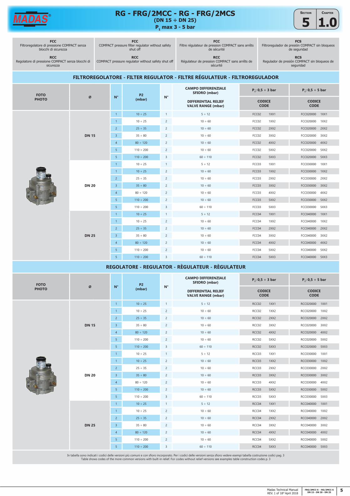
FILTROREGOLATORE - FILTER REGULATOR - FILTRE RÉGULATEUR - FILTROREGULADOR
FOTOPHOTO Ø N° P2
(mbar) N°
CAMPO DIFFERENZIALESFIORO (mbar)
DIFFERENTIAL RELIEFVALVE RANGE (mbar)
P1: 0,5 ÷ 3 bar P1: 0,5 ÷ 5 bar
CODICECODE
CODICECODE
DN 15
1 10 ÷ 25 1 5 ÷ 12 FCC02 1XX1 FCC020000 1XX1
1 10 ÷ 25 2 10 ÷ 60 FCC02 1XX2 FCC020000 1XX2
2 25 ÷ 35 2 10 ÷ 60 FCC02 2XX2 FCC020000 2XX2
3 35 ÷ 80 2 10 ÷ 60 FCC02 3XX2 FCC020000 3XX2
4 80 ÷ 120 2 10 ÷ 60 FCC02 4XX2 FCC020000 4XX2
5 110 ÷ 200 2 10 ÷ 60 FCC02 5XX2 FCC020000 5XX2
5 110 ÷ 200 3 60 ÷ 110 FCC02 5XX3 FCC020000 5XX3
DN 20
1 10 ÷ 25 1 5 ÷ 12 FCC03 1XX1 FCC030000 1XX1
1 10 ÷ 25 2 10 ÷ 60 FCC03 1XX2 FCC030000 1XX2
2 25 ÷ 35 2 10 ÷ 60 FCC03 2XX2 FCC030000 2XX2
3 35 ÷ 80 2 10 ÷ 60 FCC03 3XX2 FCC030000 3XX2
4 80 ÷ 120 2 10 ÷ 60 FCC03 4XX2 FCC030000 4XX2
5 110 ÷ 200 2 10 ÷ 60 FCC03 5XX2 FCC030000 5XX2
5 110 ÷ 200 3 60 ÷ 110 FCC03 5XX3 FCC030000 5XX3
DN 25
1 10 ÷ 25 1 5 ÷ 12 FCC04 1XX1 FCC040000 1XX1
1 10 ÷ 25 2 10 ÷ 60 FCC04 1XX2 FCC040000 1XX2
2 25 ÷ 35 2 10 ÷ 60 FCC04 2XX2 FCC040000 2XX2
3 35 ÷ 80 2 10 ÷ 60 FCC04 3XX2 FCC040000 3XX2
4 80 ÷ 120 2 10 ÷ 60 FCC04 4XX2 FCC040000 4XX2
5 110 ÷ 200 2 10 ÷ 60 FCC04 5XX2 FCC040000 5XX2
5 110 ÷ 200 3 60 ÷ 110 FCC04 5XX3 FCC040000 5XX3
REGOLATORE - REGULATOR - RÈGULATEUR - RÈGULATEUR
FOTOPHOTO Ø N° P2
(mbar) N°
CAMPO DIFFERENZIALESFIORO (mbar)
DIFFERENTIAL RELIEFVALVE RANGE (mbar)
P1: 0,5 ÷ 3 bar P1: 0,5 ÷ 5 bar
CODICECODE
CODICECODE
DN 15
1 10 ÷ 25 1 5 ÷ 12 RCC02 1XX1 RCC020000 1XX1
1 10 ÷ 25 2 10 ÷ 60 RCC02 1XX2 RCC020000 1XX2
2 25 ÷ 35 2 10 ÷ 60 RCC02 2XX2 RCC020000 2XX2
3 35 ÷ 80 2 10 ÷ 60 RCC02 3XX2 RCC020000 3XX2
4 80 ÷ 120 2 10 ÷ 60 RCC02 4XX2 RCC020000 4XX2
5 110 ÷ 200 2 10 ÷ 60 RCC02 5XX2 RCC020000 5XX2
5 110 ÷ 200 3 60 ÷ 110 RCC02 5XX3 RCC020000 5XX3
DN 20
1 10 ÷ 25 1 5 ÷ 12 RCC03 1XX1 RCC030000 1XX1
1 10 ÷ 25 2 10 ÷ 60 RCC03 1XX2 RCC030000 1XX2
2 25 ÷ 35 2 10 ÷ 60 RCC03 2XX2 RCC030000 2XX2
3 35 ÷ 80 2 10 ÷ 60 RCC03 3XX2 RCC030000 3XX2
4 80 ÷ 120 2 10 ÷ 60 RCC03 4XX2 RCC030000 4XX2
5 110 ÷ 200 2 10 ÷ 60 RCC03 5XX2 RCC030000 5XX2
5 110 ÷ 200 3 60 ÷ 110 RCC03 5XX3 RCC030000 5XX3
DN 25
1 10 ÷ 25 1 5 ÷ 12 RCC04 1XX1 RCC040000 1XX1
1 10 ÷ 25 2 10 ÷ 60 RCC04 1XX2 RCC040000 1XX2
2 25 ÷ 35 2 10 ÷ 60 RCC04 2XX2 RCC040000 2XX2
3 35 ÷ 80 2 10 ÷ 60 RCC04 3XX2 RCC040000 3XX2
4 80 ÷ 120 2 10 ÷ 60 RCC04 4XX2 RCC040000 4XX2
5 110 ÷ 200 2 10 ÷ 60 RCC04 5XX2 RCC040000 5XX2
5 110 ÷ 200 3 60 ÷ 110 RCC04 5XX3 RCC040000 5XX3
In tabella sono indicati i codici delle versioni più comuni e con sfioro incorporato. Per i codici delle versioni senza sfioro vedere esempi tabella costruzione codici pag. 3Table shows codes of the more common versions with built-in relief. For codes without relief versions see examples table construction codes p. 3
6 FRG/2MCC-S - RG/2MCC-SDN 15 - DN 20 - DN 25
Chapter
1.0SeCtion
5 P1 max 3 - 5 bar
RG - FRG/2MCC - RG - FRG/2MCS(DN 15 ÷ DN 25)
Madas Technical ManualREV. 1 of 18th April 2018
FCSFiltroregolatore di pressione senza blocchi di
sicurezza
RCSRegolatore di pressione senza blocchi di sicurezza
FCSPressure filter regulator without safety shut off
RCSPressure regulator without safety shut off
FCSFiltre régulateur de pression sans arrêts de sécurité
RCSRégulateur de pression sans arrêts de sécurité
FCSFiltroregulador de presión sin bloqueos de
seguridad
RCSRegulador de presión sin bloqueos de seguridad
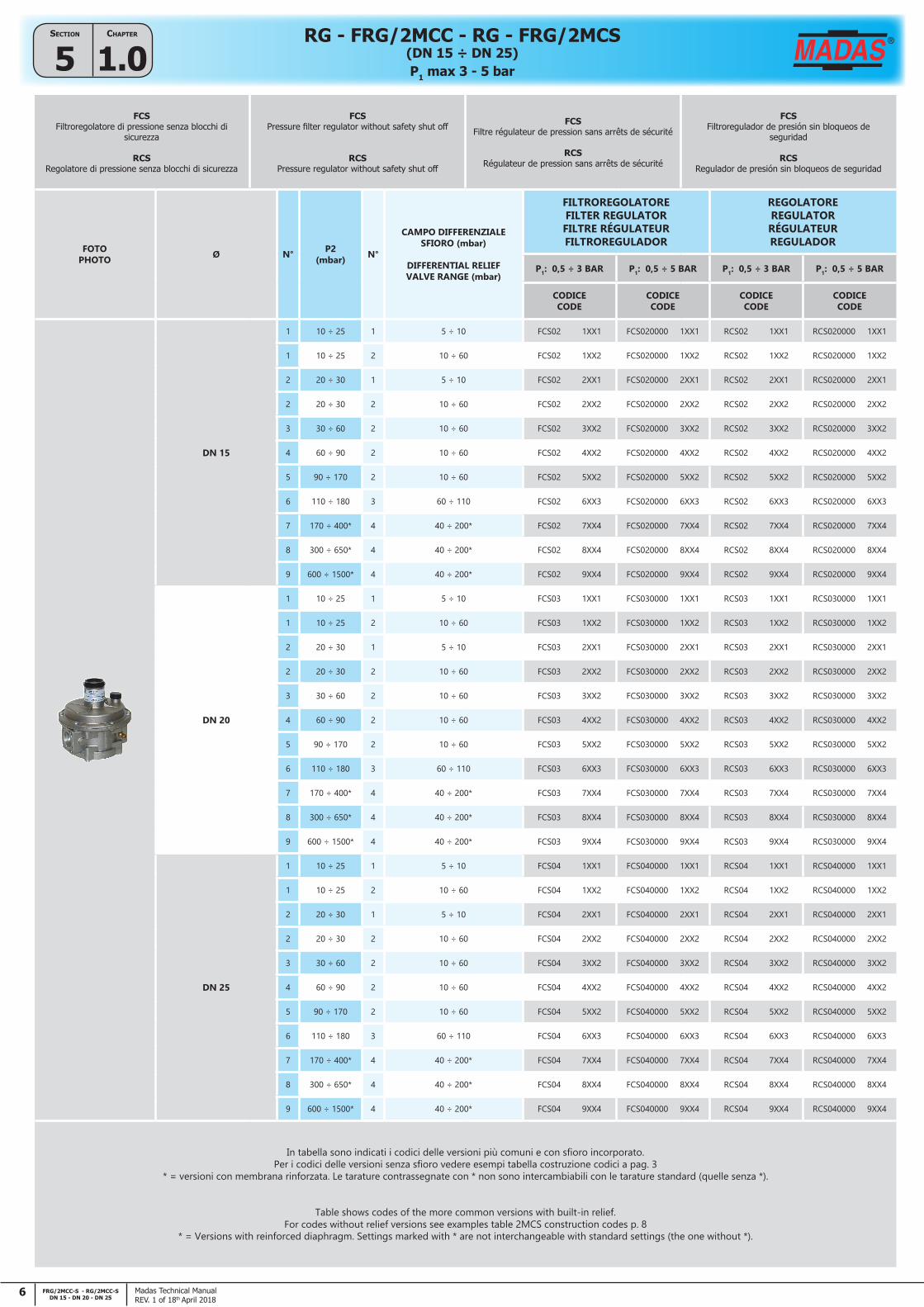
FOTOPHOTO Ø N° P2
(mbar) N°
CAMPO DIFFERENZIALESFIORO (mbar)
DIFFERENTIAL RELIEFVALVE RANGE (mbar)
FILTROREGOLATOREFILTER REGULATORFILTRE RÉGULATEURFILTROREGULADOR
REGOLATOREREGULATORRÉGULATEURREGULADOR
P1: 0,5 ÷ 3 BAR P1: 0,5 ÷ 5 BAR P1: 0,5 ÷ 3 BAR P1: 0,5 ÷ 5 BAR
CODICECODE
CODICECODE
CODICECODE
CODICECODE
DN 15
1 10 ÷ 25 1 5 ÷ 10 FCS02 1XX1 FCS020000 1XX1 RCS02 1XX1 RCS020000 1XX1
1 10 ÷ 25 2 10 ÷ 60 FCS02 1XX2 FCS020000 1XX2 RCS02 1XX2 RCS020000 1XX2
2 20 ÷ 30 1 5 ÷ 10 FCS02 2XX1 FCS020000 2XX1 RCS02 2XX1 RCS020000 2XX1
2 20 ÷ 30 2 10 ÷ 60 FCS02 2XX2 FCS020000 2XX2 RCS02 2XX2 RCS020000 2XX2
3 30 ÷ 60 2 10 ÷ 60 FCS02 3XX2 FCS020000 3XX2 RCS02 3XX2 RCS020000 3XX2
4 60 ÷ 90 2 10 ÷ 60 FCS02 4XX2 FCS020000 4XX2 RCS02 4XX2 RCS020000 4XX2
5 90 ÷ 170 2 10 ÷ 60 FCS02 5XX2 FCS020000 5XX2 RCS02 5XX2 RCS020000 5XX2
6 110 ÷ 180 3 60 ÷ 110 FCS02 6XX3 FCS020000 6XX3 RCS02 6XX3 RCS020000 6XX3
7 170 ÷ 400* 4 40 ÷ 200* FCS02 7XX4 FCS020000 7XX4 RCS02 7XX4 RCS020000 7XX4
8 300 ÷ 650* 4 40 ÷ 200* FCS02 8XX4 FCS020000 8XX4 RCS02 8XX4 RCS020000 8XX4
9 600 ÷ 1500* 4 40 ÷ 200* FCS02 9XX4 FCS020000 9XX4 RCS02 9XX4 RCS020000 9XX4
DN 20
1 10 ÷ 25 1 5 ÷ 10 FCS03 1XX1 FCS030000 1XX1 RCS03 1XX1 RCS030000 1XX1
1 10 ÷ 25 2 10 ÷ 60 FCS03 1XX2 FCS030000 1XX2 RCS03 1XX2 RCS030000 1XX2
2 20 ÷ 30 1 5 ÷ 10 FCS03 2XX1 FCS030000 2XX1 RCS03 2XX1 RCS030000 2XX1
2 20 ÷ 30 2 10 ÷ 60 FCS03 2XX2 FCS030000 2XX2 RCS03 2XX2 RCS030000 2XX2
3 30 ÷ 60 2 10 ÷ 60 FCS03 3XX2 FCS030000 3XX2 RCS03 3XX2 RCS030000 3XX2
4 60 ÷ 90 2 10 ÷ 60 FCS03 4XX2 FCS030000 4XX2 RCS03 4XX2 RCS030000 4XX2
5 90 ÷ 170 2 10 ÷ 60 FCS03 5XX2 FCS030000 5XX2 RCS03 5XX2 RCS030000 5XX2
6 110 ÷ 180 3 60 ÷ 110 FCS03 6XX3 FCS030000 6XX3 RCS03 6XX3 RCS030000 6XX3
7 170 ÷ 400* 4 40 ÷ 200* FCS03 7XX4 FCS030000 7XX4 RCS03 7XX4 RCS030000 7XX4
8 300 ÷ 650* 4 40 ÷ 200* FCS03 8XX4 FCS030000 8XX4 RCS03 8XX4 RCS030000 8XX4
9 600 ÷ 1500* 4 40 ÷ 200* FCS03 9XX4 FCS030000 9XX4 RCS03 9XX4 RCS030000 9XX4
DN 25
1 10 ÷ 25 1 5 ÷ 10 FCS04 1XX1 FCS040000 1XX1 RCS04 1XX1 RCS040000 1XX1
1 10 ÷ 25 2 10 ÷ 60 FCS04 1XX2 FCS040000 1XX2 RCS04 1XX2 RCS040000 1XX2
2 20 ÷ 30 1 5 ÷ 10 FCS04 2XX1 FCS040000 2XX1 RCS04 2XX1 RCS040000 2XX1
2 20 ÷ 30 2 10 ÷ 60 FCS04 2XX2 FCS040000 2XX2 RCS04 2XX2 RCS040000 2XX2
3 30 ÷ 60 2 10 ÷ 60 FCS04 3XX2 FCS040000 3XX2 RCS04 3XX2 RCS040000 3XX2
4 60 ÷ 90 2 10 ÷ 60 FCS04 4XX2 FCS040000 4XX2 RCS04 4XX2 RCS040000 4XX2
5 90 ÷ 170 2 10 ÷ 60 FCS04 5XX2 FCS040000 5XX2 RCS04 5XX2 RCS040000 5XX2
6 110 ÷ 180 3 60 ÷ 110 FCS04 6XX3 FCS040000 6XX3 RCS04 6XX3 RCS040000 6XX3
7 170 ÷ 400* 4 40 ÷ 200* FCS04 7XX4 FCS040000 7XX4 RCS04 7XX4 RCS040000 7XX4
8 300 ÷ 650* 4 40 ÷ 200* FCS04 8XX4 FCS040000 8XX4 RCS04 8XX4 RCS040000 8XX4
9 600 ÷ 1500* 4 40 ÷ 200* FCS04 9XX4 FCS040000 9XX4 RCS04 9XX4 RCS040000 9XX4
In tabella sono indicati i codici delle versioni più comuni e con sfioro incorporato. Per i codici delle versioni senza sfioro vedere esempi tabella costruzione codici a pag. 3
* = versioni con membrana rinforzata. Le tarature contrassegnate con * non sono intercambiabili con le tarature standard (quelle senza *).
Table shows codes of the more common versions with built-in relief.For codes without relief versions see examples table 2MCS construction codes p. 8
* = Versions with reinforced diaphragm. Settings marked with * are not interchangeable with standard settings (the one without *).
7FRG/2MCC-S - RG/2MCC-SDN 15 - DN 20 - DN 25
Chapter
1.0SeCtion
5
Madas Technical ManualREV. 1 of 18th April 2018
P1 max 3 - 5 bar
RG - FRG/2MCC - RG - FRG/2MCS(DN 15 ÷ DN 25)
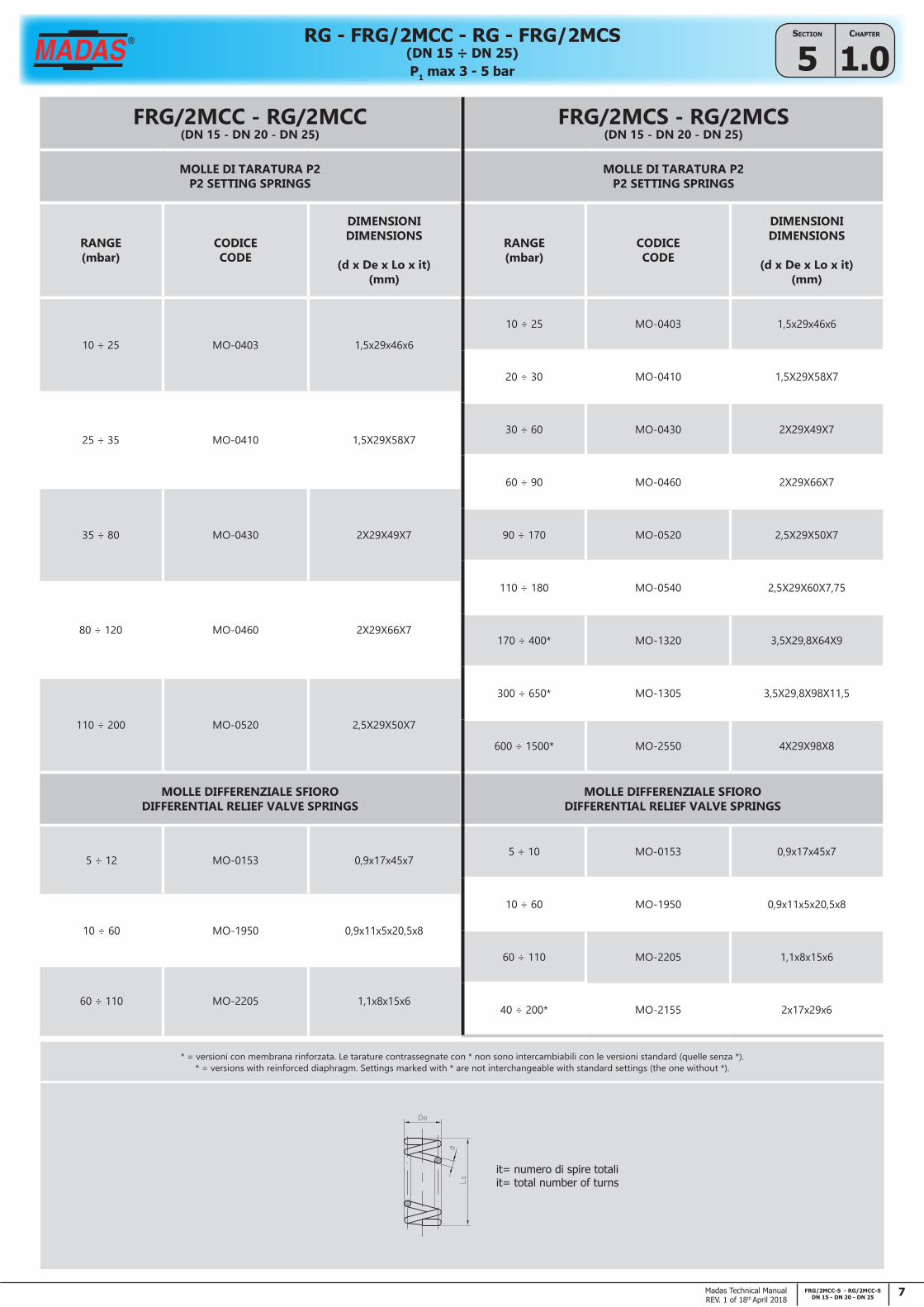
* = versioni con membrana rinforzata. Le tarature contrassegnate con * non sono intercambiabili con le versioni standard (quelle senza *).* = versions with reinforced diaphragm. Settings marked with * are not interchangeable with standard settings (the one without *).
it= numero di spire totaliit= total number of turns
FRG/2MCC - RG/2MCC(DN 15 - DN 20 - DN 25)
MOLLE DI TARATURA P2P2 SETTING SPRINGS
RANGE(mbar)
CODICECODE
DIMENSIONIDIMENSIONS
(d x De x Lo x it)(mm)
10 ÷ 25 MO-0403 1,5x29x46x6
25 ÷ 35 MO-0410 1,5X29X58X7
35 ÷ 80 MO-0430 2X29X49X7
80 ÷ 120 MO-0460 2X29X66X7
110 ÷ 200 MO-0520 2,5X29X50X7
MOLLE DIFFERENZIALE SFIORODIFFERENTIAL RELIEF VALVE SPRINGS
5 ÷ 12 MO-0153 0,9x17x45x7
10 ÷ 60 MO-1950 0,9x11x5x20,5x8
60 ÷ 110 MO-2205 1,1x8x15x6
FRG/2MCS - RG/2MCS(DN 15 - DN 20 - DN 25)
MOLLE DI TARATURA P2P2 SETTING SPRINGS
RANGE(mbar)
CODICECODE
DIMENSIONIDIMENSIONS
(d x De x Lo x it)(mm)
10 ÷ 25 MO-0403 1,5x29x46x6
20 ÷ 30 MO-0410 1,5X29X58X7
30 ÷ 60 MO-0430 2X29X49X7
60 ÷ 90 MO-0460 2X29X66X7
90 ÷ 170 MO-0520 2,5X29X50X7
110 ÷ 180 MO-0540 2,5X29X60X7,75
170 ÷ 400* MO-1320 3,5X29,8X64X9
300 ÷ 650* MO-1305 3,5X29,8X98X11,5
600 ÷ 1500* MO-2550 4X29X98X8
MOLLE DIFFERENZIALE SFIORODIFFERENTIAL RELIEF VALVE SPRINGS
5 ÷ 10 MO-0153 0,9x17x45x7
10 ÷ 60 MO-1950 0,9x11x5x20,5x8
60 ÷ 110 MO-2205 1,1x8x15x6
40 ÷ 200* MO-2155 2x17x29x6

8 FRG/2MCC-S - RG/2MCC-SDN 15 - DN 20 - DN 25
Chapter
1.0SeCtion
5 P1 max 3 - 5 bar
RG - FRG/2MCC - RG - FRG/2MCS(DN 15 ÷ DN 25)
Madas Technical ManualREV. 1 of 18th April 2018
DIMENSIONI DI INGOMBRO IN MM - OVERALL DIMENSIONS IN MMMESURES D’ENCOMBREMENT EN MM - DIMENSIONES EN MM
COMPACT VERSION(2MCC)
STANDARD VERSION(2MCS) A
BC
P2 < 200 mbar P2 > 200 mbar
DN 15 - DN 20 - DN 25 - 120 147 - 94
- DN 15 - DN 20 - DN 25 120 147 194 140
VERSIONI CON FLANGE - VERSIONS WITH FLANGESVERSIONS AVEC BRIDES - VERSIÓNES CON BRIDAS
COMPACT VERSION(2MCC)
STANDARD VERSION(2MCS) A
BC
P2 < 200 mbar P2 > 200 mbar
DN 25 FL. - 191 163 - 115
- DN 25 FL. 191 166 212 140
Standard (2MCS)Compact (2MCC)
Standard (2MCS)Compact (2MCC)

9FRG/2MCC-S - RG/2MCC-SDN 15 - DN 20 - DN 25
Chapter
1.0SeCtion
5
Madas Technical ManualREV. 1 of 18th April 2018
P1 max 3 - 5 bar
RG - FRG/2MCC - RG - FRG/2MCS(DN 15 ÷ DN 25)
PORTATE REGOLATORI DN 15 - 20 - 25 / CAPACITIES OF REGULATORS DN 15 - 20 - 25DÉBIT DES RÉGULATEURS DN 15 - 20 - 25 / CAUDAL DE LOS REGULADORES DN 15 - 20 - 25
(Nm3/h) Gas naturale - Natural Gas - Gaz naturel - Gas natural
ModelliModelsModèlesModelos
P2 (mbar)
Pressione di ingresso - Inlet Pressure - Pression d'entrée - Presión de entrada
0,5 bar 1 bar 2 bar 3 - 4bar 5 bar
2MCC COMPACTDN 15 - 20 -25
20 25 25 25 25 25
30 25 25 25 25 25
50 25 25 25 25 25
100 25 25 25 25 25
200 25 25 25 25 25
2MCS STANDARD
DN 15
20 25 27 30 30 37
30 37 37 37 39 39
50 50 50 50 50 50
100 60 62 62 62 62
200 85 85 85 85 85
300 70 100 100 100 100
350 40 75 90 90 90
400 40 90 100 100 100
2MCSSTANDARD
DN 20
20 42 42 50 50 50
30 50 50 55 55 55
50 70 70 70 70 70
100 100 100 100 100 100
200 86 100 100 100 100
300 86 100 100 100 100
350 70 120 120 120 120
400 65 120 120 120 120
2MCSSTANDARD
DN 25
20 100 100 100 100 100
30 100 100 100 100 100
50 100 100 100 100 100
100 100 100 100 100 100
200 100 100 100 100 100
300 100 100 100 100 100
350 75 120 120 120 120
400 70 120 120 120 120
Dati ricavati SENZA L'UTILIZZO del tubetto sensore esternoData obtained WITHOUT USING of external sensor tube
Données obtenues SANS L'UTILISATION" du tube capteur extérieuDatos obtenidos SIN USAR el tubo sensor externo
Aria - Air - Air - Aire = 0,806Gas naturale - Natural Gas - Gaz naturel - Gas natural = 1
Gas di città - Town gas - Gaz de ville - Gas de ciudad = 1.177GPL - LPG - Gaz de pétrole liquéfié - Gas líquido = 0.62

10 FRG/2MCC-S - RG/2MCC-SDN 15 - DN 20 - DN 25
Chapter
1.0SeCtion
5 P1 max 3 - 5 bar
RG - FRG/2MCC - RG - FRG/2MCS(DN 15 ÷ DN 25)
Madas Technical ManualREV. 1 of 18th April 2018
FRG/2MBC P2 = 20 mbar
0
5
10
15
20
25
30
0 1 2 3 4 5 6 7 8 9 10 11 12 13 14 15 16 17 18 19 20 21 22 23 24 25 26 27 28 29 30 31 32
P2
(mb
ar)
P1=0.5 bar P1=2 bar P1=5 bar
+ 10%
- 10%
Portata (m3/h aria) - Flow rate (m3/h air) - Debit (m3/h air) - Caudal (m3/h aire)
Curve di stabilizzazione (versione COMPACT) - Stabilization curves (COMPACT version)Courbes de stabilisation (version COMPACT) - Curvas de estabilización (versión COMPACT)
FRG/2MBC P2 = 30 mbar
22
25
28
31
34
37
40
0 1 2 3 4 5 6 7 8 9 10 11 12 13 14 15 16 17 18 19 20 21 22 23 24 25 26 27 28 29 30 31 32
P2
(mb
ar)
P1=0.5 bar P1=2 bar P1=5 bar
+ 10%
- 10%
Portata (m3/h aria) - Flow rate (m3/h air) - Debit (m3/h air) - Caudal (m3/h aire)
FRG/2MBC P2 = 100 mbar
86
91
96
101
106
111
0 1 2 3 4 5 6 7 8 9 10 11 12 13 14 15 16 17 18 19 20 21 22 23 24 25 26 27 28 29 30 31 32
P2
(mb
ar)
P1=0.5 bar P1=2 bar P1=5 bar
+ 10%
- 10%
Portata (m3/h aria) - Flow rate (m3/h air) - Debit (m3/h air) - Caudal (m3/h aire)
FRG/2MCC P2 = 20 mbar
FRG/2MCC P2 = 30 mbar
FRG/2MCC P2 = 100 mbar

11FRG/2MCC-S - RG/2MCC-SDN 15 - DN 20 - DN 25
Chapter
1.0SeCtion
5
Madas Technical ManualREV. 1 of 18th April 2018
P1 max 3 - 5 bar
RG - FRG/2MCC - RG - FRG/2MCS(DN 15 ÷ DN 25)
FRG/2MB P2 = 20 mbar
0
5
10
15
20
25
30
0 5 10 15 20 25 30 35 40 45 50 55 60 65 70 75 80 85
P2
(m
ba
r)
P1=0.5 bar P1=2 bar P1=5 bar
+ 10%
- 10%
Portata (m3/h aria) - Flow rate (m3/h air) - Debit (m3/h air) - Caudal (m3/h aire)
Curve di stabilizzazione (versione STANDARD) - Stabilization curves (STANDARD version)Courbes de stabilisation (version STANDARD) - Curvas de estabilización (versión STANDARD)
FRG/2MB P2 = 30 mbar
22
25
28
31
34
37
40
0 5 10 15 20 25 30 35 40 45 50 55 60 65 70 75 80 85
P2
(m
ba
r)
P1=0.5 bar P1=2 bar P1=5 bar
+ 10%
- 10%
Portata (m3/h aria) - Flow rate (m3/h air) - Debit (m3/h air) - Caudal (m3/h aire)
FRG/2MB P2 = 100 mbar
82
88
94
100
106
112
118
0 5 10 15 20 25 30 35 40 45 50 55 60 65 70 75 80 85
P2
(mb
ar)
P1=0.5 bar P1=2 bar P1=5 bar
+ 10%
- 10%
Portata (m3/h aria) - Flow rate (m3/h air) - Debit (m3/h air) - Caudal (m3/h aire)
FRG/2MCS P2 = 20 mbar
FRG/2MCS P2 = 30 mbar
FRG/2MCS P2 = 100 mbar

12 FRG/2MCC-S - RG/2MCC-SDN 15 - DN 20 - DN 25
Chapter
1.0SeCtion
5 P1 max 3 - 5 bar
RG - FRG/2MCC - RG - FRG/2MCS(DN 15 ÷ DN 25)
Madas Technical ManualREV. 1 of 18th April 2018
IMPORTANTE
Consultare attentamente il manuale di istruzioni a corredo del prodotto per conoscere le avvertenze e le modalità di installazione e manutenzione
IMPORTANT
Read carefully the operating instructions manual supplied with the product for the warnings and installation and maintenance procedures
IMPORTANT
Consulter attent ivement le manuel d'instructions fourni avec le produit pour connaître les mises en garde et les modes d'installation et d'entretien
IMPORTANTE
Consulte atentamente el manual de instrucciones que se entrega junto con el producto, para las advertencias y las modalidades de instalación y de mantenimiento