© Lawrie Kirk 2010 Strategic Communication Planning Lawrie Kirk Visiting Fellow CPAS ANU
Upload
laura-littleCategory
view
241download
0
RFQ Thermal Analysis
Scott Lawrie
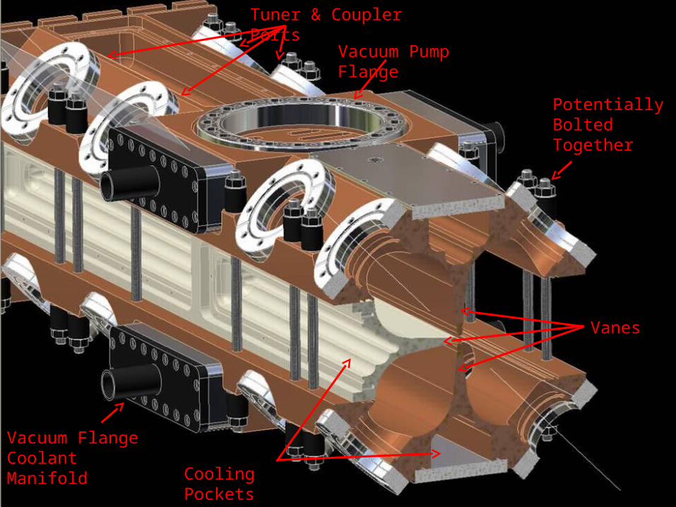
Vacuum Pump Flange
Vacuum Flange Coolant Manifold
Cooling Pockets Milled Into Vanes
Potentially Bolted Together
Tuner & Coupler Ports
Vanes
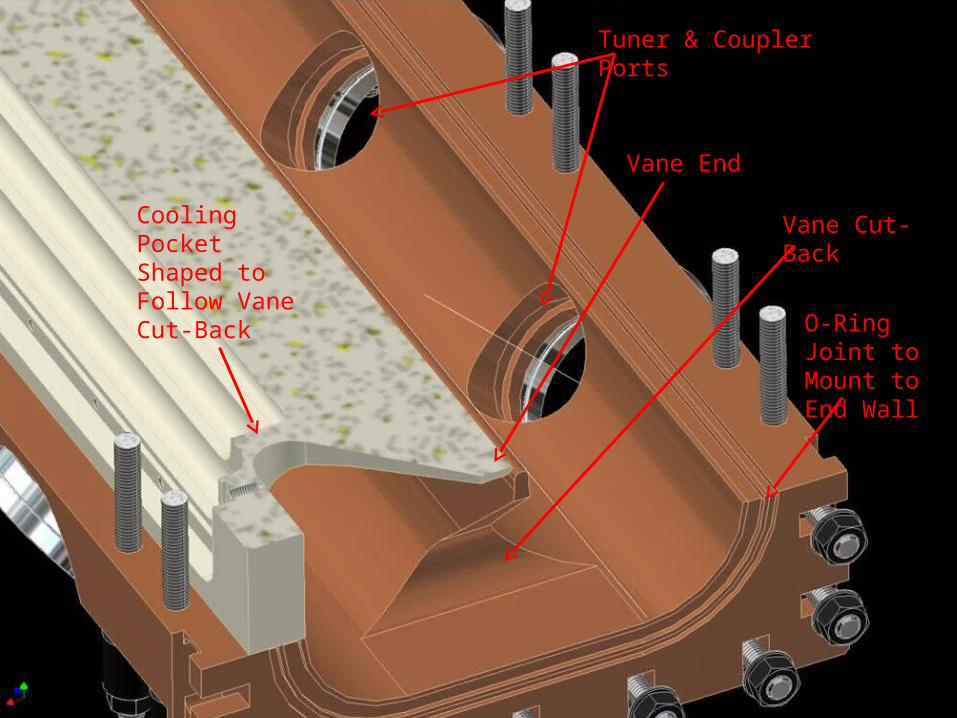
Vane Cut-Back
Vane End
Cooling Pocket Shaped to Follow Vane Cut-Back
Tuner & Coupler Ports
O-Ring Joint to Mount to End Wall

RFQs normally use cooling channels
Indian SNS:Six per quadrant
American SNS:Four per quadrant
Chinese SNS:Five per quadrant
HINS (FNAL):Three per quadrant

Replace distributed channels with one cooling pocket
Set of cooling channels drilled along length of vane

Replace distributed channels with one cooling pocket

Pocket milled into vane from air side
Plate bolted on to cover the pocket and allow water in/out
Baffle attached to cover plate; shaped to leave 2-3mm gap
Water flow directed along gap between pocket and baffle
Replace distributed channels with one cooling pocket

Cooling PocketDisadvantages Advantages
• New, untested design
• Complicated water flow
• Unknown cooling efficiency
• Lots of material removed
• Novel
• Allows for 3D heat distribution
• Simple to manufacture
• No vacuum to water interfaces
• Flow can be directed where
needed
• Highly configurable
• Easily adjusted & maintained
• Gap can be replaced with
channels
• Could be the new standard!
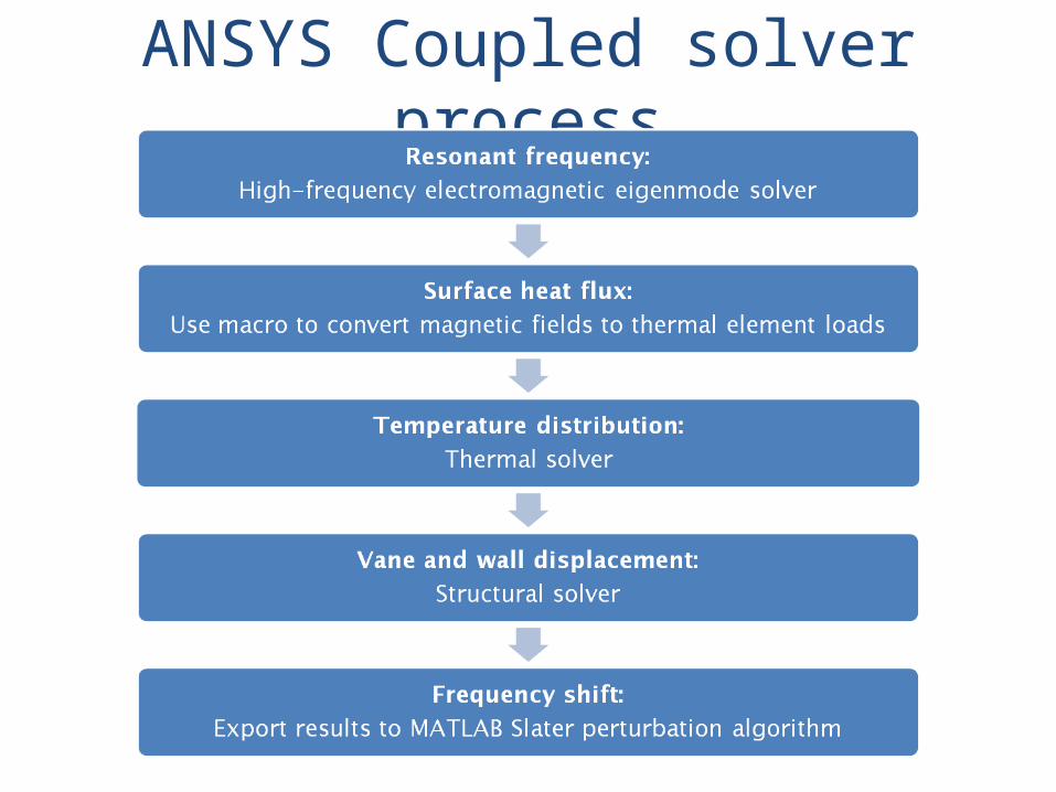
ANSYS Coupled solver process

Model geometry(from Autodesk Inventor)

Simplified model with applied boundary conditions
Vacuum body inside cavity
Vacuum port pumping-slot cooling channels
Tuner & coupler ports with integrated cooling
Cooling pocket and baffle
Vane end cut-back

Eigenmode SolverSurface H-Field Results
Highest magnetic field intensity at vane end cut-back
Magnetic field strongest at corners e.g. at tuners
2m

Eigenmode SolverMagnetic Field Vector Results
H-Field flowing around vane cut-backs
H-Field flowing past tuner port and vacuum pump slots

Eigenmode SolverSurface E-Field Results

Eigenmode SolverElectric Field Vector Results
Quadrupole Mode333.56 MHz
(should be 324 MHz)Dipole Modes 330.02 MHz
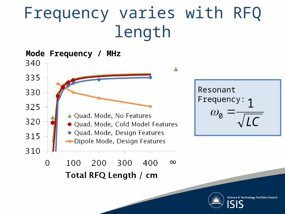
Frequency varies with RFQ length
Mode Frequency / MHz
LC
10
Resonant Frequency:

Total Surface Power Loss
surface
iiisolver dAHP 2
2
2
2 isolver
reali HP
PF
00f
Heat Flux Per Element
Psolver = Calculated total surface power (W)ρ = Surface resistance (Ω)H = Tangential magnetic field at surface (T)dA = Area of surface mesh element (m2)f = Cavity resonant frequency (Hz)µ0 = permeability of free space (H m-1)σ = Conductivity of cavity walls (S m-1)F = Heat flux due to surface losses (W m-2)Preal = Expected total surface power (W)
where:

Surface heat flux
Large power losses at vane end cut-back
Relatively high heat loads at coupler, tuner and vacuum pump ports
Heat flux / Wm-2
800 kW total peak RF power in 4 m RFQ 2.5 kW average power in this 1/32 model
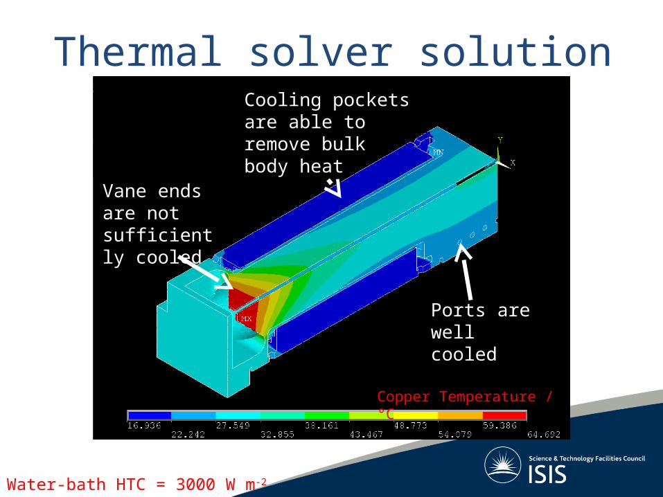
Thermal solver solution
Water-bath HTC = 3000 W m-2 K-1
Ports are well cooled
Cooling pockets are able to remove bulk body heat
Vane ends are not sufficiently cooled
Copper Temperature / °C

Structural solver solution
Walls move outward
Vanes move inward
Net 25 µm transverse expansion of vanes is within machining tolerances
Longitudinal expansion of vane ends is unacceptably large
Y-displacement Z-displacement
Vane ends grow toward end wall by 70 µm

Frequency shift vs. RF powerFrequency Decrease / kHzMaximum Temperature / °C
Cooling Pocket HTC = 1000 Wm-2K-1
Cooling Pocket HTC = 3000 Wm-2K-1
Vane end temperature
Cavity frequency shift

Max Temperature = 37 °C
60W input RF power
ANSYS Simulation
Cold Model Tests
Temperature Rise
15 °C 15.6 °C
Frequency Shift
-78 kHz -89 kHz
Max Structural Deformation = 0.3 mmRFQ cold model with 60 W DC input RF power and no cooling applied.

Conclusions
• FETS RFQ will have a novel cooling system• ANSYS used to assess performance• Full 4m RFQ will have a higher frequency• Cooling pockets successfully remove RF
power• Vane end not sufficiently cooled• Vane displacements should not affect beam• CFD simulations needed to predict HTCs• Overall, cooling strategy seems to work!