RFID UHF Temperature Sensor Tags Initialization and ... · RFID UHF Temperature Sensor Tags...
7
RFID UHF Temperature Sensor Tags Initialization and Application Matea Božić-Kudrić, Petar Šolić, and Nikola Rožić Faculty of Electrical Engineering, Mechanical Engineering and Naval Architecture University of Split R. Boškovića 32, 21000 Split, Croatia E-mail: {matea.bozic-kudric, psolic, rozic}@fesb.hr Abstract – Radio Frequency Identification (RFID) has found its appliance in many areas but most common use of RFID technology is for tracking various goods. In this paper the system for monitoring temperature of instruments inside the laboratory is presented. System is composed of Caen RT0005 UHF RFID tags with integrated temperature sensor, Alien 9900 UHF RFID reader and UHF RFID Alien patch antennas. Caen RT0005 tags are semi-passive tags which provide temperature logging once when they are initialized. Proposed system represents safe surveillance of expensive instruments prone to overheating. We proposed the software which provides instruments tracking inside the laboratory, initialization and writing of sensor tags, temperature tracking and alarms notification. There are two kinds of temperature alarms which can be alerted: i) when temperature increases over pre-set temperature limit, ii) when temperature is increased rapidly inside pre-set time interval. Experimental results of proposed application are induced at the end of the paper along with the advantages and disadvantages of the proposed system. Keywords – RFID technology, UHF sensor tags, tags programming, temperature sensing, alarm, Caen tags, Alien reader I. INTRODUCTION In paper [1] we proposed system for object tracking and monitoring by using RFID technology. We described software with the MySQL database for simple objects finding inside the laboratory. RFID system was composed of Alien RFID reader, four UHF RFID antennas and BAP (Battery Assisted Passive) tags which we use for objects tagging. In this paper we extended pre-proposed RFID system with Caen UHF RFID BAP tags with integrated temperature sensor. By using sensor tags, safer way for objects monitoring is enabled with regard to the possibility of temperature monitoring of some objects e.g. expensive instruments inside the laboratory which are prone to the overheating due to constant usage. RFID technology is growing rapidly in many ways as an effective wireless technology for object identification. The integration of sensors for monitoring some physical parameter like temperature, humidity, pressure, etc. into semi-passive RFID tags has generated huge interest in RFID technology development [2-4]. But still there are not many manufacturers at the market who offer tags that incorporate sensing capabilities. Some of them which are worth to mention are SL900A sensory tag by Austria Micro Systems (AMS), the Easy2Log tag by CAEN RFID, and the SensTAG by Phase IV [3]. However, none of those tags are completely compliant with RFID standards and regulations and they cannot be programed/written as regular tags. RFID semi-passive tags with integrated temperature, humidity, pressure or any other sensor are not common RFID semi-passive tags since that they are equipped with sensor and are more expensive than regular tags but they contain the same identification functions as regular tags. Other disadvantage is limited life time of sesor tags due to battery usage to power its circutary which can be solved like it is proposed in [5]. RFID UHF tags are identification devices of RFID system and contain microchip attached to an antenna. They are communicating with a RFID reader by sending its identification number but they can contain an additional data like those with sensor do. RFID tags can be passive, semi- passive or active due to battery presence of absence. Semi- passive or BAP (Battery Assisted Passive) are those who have battery to power its circuitry and they are communicating with the reader in the same way as the passive tags by using backscattered communication [6]. In this work we will describe how to program sensor tags – Caen RT0005 with Alien 9900 reader. There will be presented how to use sensor tag outside of a perishable items monitoring during the transport which means that there are set into the laboratory environment. In Section II the Caen RT0005 will be described: i) how to initialize it to start temperature logging, ii) its memory banks and memory structure. Section III is about sensor tag programing with Alien 9900 reader, and Section IV and V describe experimental set-ups for programing tag testing and for testing instruments temperature logging. A conclusion and obtained results are induced at the end of the paper. II. CAEN RT0005 TEMPERATURE TAGS Tags with integrated temperature sensor Caen RT0005 are semi-passive UHF tags compatible to the EPC Class1 Gen2 ISO18000-6C standard [7]. They have possibility of temperature logging according to the user preferences during food transport or monitoring temperature of different laboratory instruments as we described in our paper. To start temperature logging user needs to configure some memory registers of RT0005 tag which are part of its User memory bank. Once configured, tag can work as temperature logger as long as its battery doesn’t run out. When the battery runs out or if we programmatically or manually stop its temperature logging all registers are being reset which is main disadvantage of this tag. Main problem in tag’s registers temperature logging reconfiguration is the time we need to invest in registers WICT/I - 25309 - 1709 © SoftCOM 2104
Transcript of RFID UHF Temperature Sensor Tags Initialization and ... · RFID UHF Temperature Sensor Tags...
RFID UHF Temperature Sensor Tags Initialization
and Application Matea Božić-Kudrić, Petar Šolić, and Nikola Rožić
Faculty of Electrical Engineering, Mechanical Engineering and Naval Architecture
University of Split
R. Boškovića 32, 21000 Split, Croatia
E-mail: {matea.bozic-kudric, psolic, rozic}@fesb.hr
Abstract – Radio Frequency Identification (RFID) has found
its appliance in many areas but most common use of RFID
technology is for tracking various goods. In this paper the system
for monitoring temperature of instruments inside the laboratory
is presented. System is composed of Caen RT0005 UHF RFID
tags with integrated temperature sensor, Alien 9900 UHF RFID
reader and UHF RFID Alien patch antennas. Caen RT0005 tags
are semi-passive tags which provide temperature logging once
when they are initialized. Proposed system represents safe
surveillance of expensive instruments prone to overheating. We
proposed the software which provides instruments tracking
inside the laboratory, initialization and writing of sensor tags,
temperature tracking and alarms notification. There are two
kinds of temperature alarms which can be alerted: i) when
temperature increases over pre-set temperature limit, ii) when
temperature is increased rapidly inside pre-set time interval.
Experimental results of proposed application are induced at the
end of the paper along with the advantages and disadvantages of
the proposed system.
Keywords – RFID technology, UHF sensor tags, tags
programming, temperature sensing, alarm, Caen tags, Alien
reader
I. INTRODUCTION
In paper [1] we proposed system for object tracking and
monitoring by using RFID technology. We described software
with the MySQL database for simple objects finding inside the
laboratory. RFID system was composed of Alien RFID reader,
four UHF RFID antennas and BAP (Battery Assisted Passive)
tags which we use for objects tagging. In this paper we
extended pre-proposed RFID system with Caen UHF RFID
BAP tags with integrated temperature sensor. By using sensor
tags, safer way for objects monitoring is enabled with regard
to the possibility of temperature monitoring of some objects
e.g. expensive instruments inside the laboratory which are
prone to the overheating due to constant usage.
RFID technology is growing rapidly in many ways as an
effective wireless technology for object identification. The
integration of sensors for monitoring some physical parameter
like temperature, humidity, pressure, etc. into semi-passive
RFID tags has generated huge interest in RFID technology
development [2-4]. But still there are not many manufacturers
at the market who offer tags that incorporate sensing
capabilities. Some of them which are worth to mention are
SL900A sensory tag by Austria Micro Systems (AMS), the
Easy2Log tag by CAEN RFID, and the SensTAG by Phase IV
[3]. However, none of those tags are completely compliant
with RFID standards and regulations and they cannot be
programed/written as regular tags. RFID semi-passive tags
with integrated temperature, humidity, pressure or any other
sensor are not common RFID semi-passive tags since that they
are equipped with sensor and are more expensive than regular
tags but they contain the same identification functions as
regular tags. Other disadvantage is limited life time of sesor
tags due to battery usage to power its circutary which can be
solved like it is proposed in [5].
RFID UHF tags are identification devices of RFID system
and contain microchip attached to an antenna. They are
communicating with a RFID reader by sending its
identification number but they can contain an additional data
like those with sensor do. RFID tags can be passive, semi-
passive or active due to battery presence of absence. Semi-
passive or BAP (Battery Assisted Passive) are those who have
battery to power its circuitry and they are communicating with
the reader in the same way as the passive tags by using
backscattered communication [6].
In this work we will describe how to program sensor tags –
Caen RT0005 with Alien 9900 reader. There will be presented
how to use sensor tag outside of a perishable items monitoring
during the transport which means that there are set into the
laboratory environment. In Section II the Caen RT0005 will be
described: i) how to initialize it to start temperature logging,
ii) its memory banks and memory structure. Section III is
about sensor tag programing with Alien 9900 reader, and
Section IV and V describe experimental set-ups for
programing tag testing and for testing instruments temperature
logging. A conclusion and obtained results are induced at the
end of the paper.
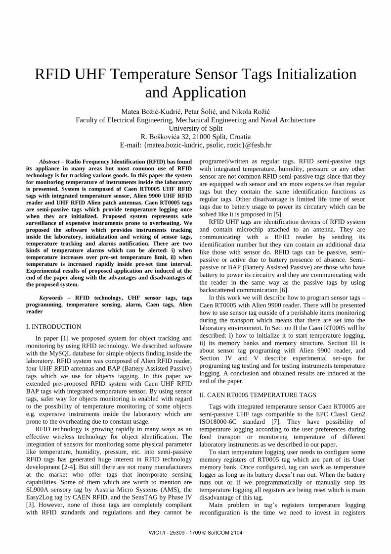
II. CAEN RT0005 TEMPERATURE TAGS
Tags with integrated temperature sensor Caen RT0005 are
semi-passive UHF tags compatible to the EPC Class1 Gen2
ISO18000-6C standard [7]. They have possibility of
temperature logging according to the user preferences during
food transport or monitoring temperature of different
laboratory instruments as we described in our paper.
To start temperature logging user needs to configure some
memory registers of RT0005 tag which are part of its User
memory bank. Once configured, tag can work as temperature
logger as long as its battery doesn’t run out. When the battery
runs out or if we programmatically or manually stop its
temperature logging all registers are being reset which is main
disadvantage of this tag.
Main problem in tag’s registers temperature logging
reconfiguration is the time we need to invest in registers
WICT/I - 25309 - 1709 © SoftCOM 2104
configuration. Constrains for writing tags are greater than for
its reading [8]. Writing range is smaller than reading range and
supports only one tag in the write field at the time, and it takes
more time to write tag than to read it etc.
RFID Gen2 tags implement 4 memory banks:
RESERVED, EPC (Electronic Product Code), TID (Tag
Identification) and USER bank [9]. User memory bank
contains all the configuration registers and the logging
memory. RT0005 temperature tag contains 74 programmable
memory registers but for the needs of the proposed system
only four registers should be configured. Registers that needs
to be configured are described hereafter:
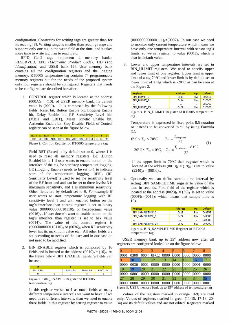
1. CONTROL register which is located at the address
(000A)h = (10)d of USER memory bank. Its default
value is (0000)h . It is composed by the following
fields: Reset bit, Button Enable bit, Logging Enable
bit, Delay Enable bit, RF Sensitivity Level bits
(MBIT and LBIT), Mean Kinetic Enable bit,
Arrhenius Enable bit, Stop Disable. Fields of Control
register can be seen at the figure below.
Figure 1. Control Register of RT0005 temperature tag
Field RST (Reset) is by default set to 0, where 1 is
used to reset all memory registers. BE (Button
Enable) bit is 1 if user wants to enable button on the
interface of the tag for start/stop temperature logging.
LE (Logging Enable) needs to be set to 1 to indicate
start of the temperature logging. RFSL (RF
Sensitivity Level) is used to set the sensitivity level
of the RF front-end and can be set to three levels: 3 is
maximum sensitivity, and 1 is minimum sensitivity.
Other fields are by default set to 0. For example if
user wants to start temperature logging with RF
sensitivity level 1 and with enabled button on the
tag’s interface than control register is set to binary
value (0000000000010110)b or hexadecimal value
(0016)h . If user doesn’t want to enable button on the
tag’s interface than register is set to hex value
(0014)h. The value of the control register is
(0000000000110110)b or (0036)h when RF sensitivity
level has its maximum value etc. All other fields are
set according to needs of the user and in our case do
not need to be modified.
2. BIN_ENABLE register which is composed by 16
fields and is located at the address (0010)h = (16)d. At
the figure below BIN_ENABLE register’s fields can
be seen.
Figure 2. BIN_ENABLE Register of RT0005
temperature tag
In this register we set to 1 as much fields as many
different temperature intervals we want to have. If we
need three different intervals, than we need to enable
three fields in this register by setting register to value
(0000000000000111)b=(0007)h. In our case we need
to monitor only current temperature which means we
have only one temperature interval with sensor tag’s
limits, so we set register to value (0001)h which is
also its default value.
3. Lower and upper temperature intervals are set in
BIN_HLIMIT registers. We need to specify upper
and lower limit of one register. Upper limit is upper
limit of a tag 70°C and lower limit is by default set to
lower limit of a tag which is -20°C as can be seen at
the Figure 3.
Figure 3. BIN_HLIMIT Register of RT0005 temperature
tag
Temperature is expressed in fixed point 8.5 notation
so it needs to be converted to °C by using Formula
(1).
32
8192,020
32,700
sfixedpoint
sfixedpoint
TTCTC
TTCTC
CC
CC (1)
If the upper limit is 70°C than register which is
located at the address (0013)h = (19)d is set to value
(2240)d = (08C0)h.
4. Optionally we can define sample time interval by
setting BIN_SAMPLETIME register to value of the
time in seconds. First field of the register which is
located at the address (0023)h = (35)d is set to value
(000F)h=(0015)d which means that sample time is
15s.
Figure 4. BIN_SAMPLETIME Register of RT0005
temperature tag
USER memory bank up to 35th address now after all
registers are configured looks like on the figure below:
0 1 2 3 4 5 6 7 8
0001 0300 0004 0FC2 0000 0000 0000 0000 0000
9 10 11 12 13 14 15 16 17
0000 0036 0001 0000 0000 0000 0000 0001 0000
18 19 20 21 22 23 24 25 26
0000 080C 0000 0000 0000 0000 0000 0000 0000
27 28 29 30 31 32 33 34 35
0000 0000 0000 0000 0000 0000 0000 0000 0001 Figure 5. USER memory bank up to 35th address of temperature tag
Values of the registers marked in orange (0-9) are read
only. Values of registers marked in green (11-15, 17-18, 20-
34) are its default values and are not edited. Registers marked
WICT/I - 25309 - 1709 © SoftCOM 2104
in blue (10, 16, 19, 35) are configured registers with its new
values.
III. PROGRAMING RFID UHF TAGS
A. Programing RFID tags
Programing/writing of the RFID tags is process which is
affected by volatile RF communication of the RFID reader and
tags [10] and thus is not always accurately. To increase the
accuracy of writing tags the communication range should be
decreased and no obstacles should be between the reader and
the tag. Write command according to EPC Class-1
Generation-2 UHF RFID protocol allows a reader to write a
word in a tag’s memory banks. Write command is composed
of following fields: memory bank which specifies which
memory bank will be affected, word pointer which specifies
the word address for the memory to write and data which
contains a 16-bit word to be written [11].
Software for multiple USER memory bank registers
programing is proposed and described hereafter.
B. Software for RT0005 temperature tags programing
Alien 9900 RFID reader and its read/write commands are
used for programing sensor tags. Alien RFID reader can be
programmatically controlled by using Microsoft.NET
Software Development Environment [12] as is a Visual Studio
which we used to write proposed software program in C#
language. Program is user friendly and provides to a user
simple and fast RT0005 tag’s registers configuration.
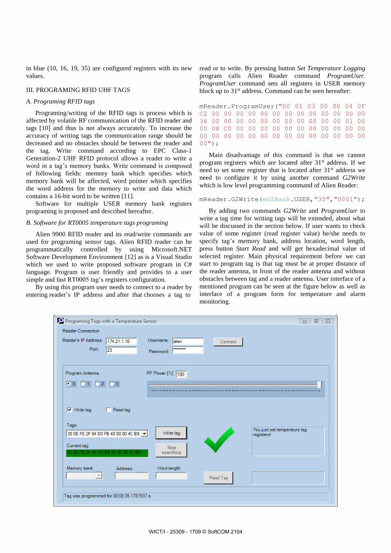
By using this program user needs to connect to a reader by
entering reader’s IP address and after that chooses a tag to
read or to write. By pressing button Set Temperature Logging
program calls Alien Reader command ProgramUser.
ProgramUser command sets all registers in USER memory
block up to 31st address. Command can be seen hereafter:
mReader.ProgramUser("00 01 03 00 00 04 0F
C2 00 00 00 00 00 00 00 00 00 00 00 00 00
36 00 00 00 00 00 00 00 00 00 00 00 01 00
00 08 C0 00 00 00 00 00 00 00 00 00 00 00
00 00 00 00 00 00 00 00 00 00 00 00 00 00
00");
Main disadvantage of this command is that we cannot
program registers which are located after 31st address. If we
need to set some register that is located after 31st address we
need to configure it by using another command G2Write
which is low level programming command of Alien Reader:
mReader.G2Write(eG2Bank.USER,"35","0001");
By adding two commands G2Write and ProgramUser to
write a tag time for writing tags will be extended, about what
will be discussed in the section below. If user wants to check
value of some register (read register value) he/she needs to
specify tag’s memory bank, address location, word length,
press button Start Read and will get hexadecimal value of
selected register. Main physical requirement before we can
start to program tag is that tag must be at proper distance of
the reader antenna, in front of the reader antenna and without
obstacles between tag and a reader antenna. User interface of a
mentioned program can be seen at the figure below as well as
interface of a program form for temperature and alarm
monitoring.
WICT/I - 25309 - 1709 © SoftCOM 2104
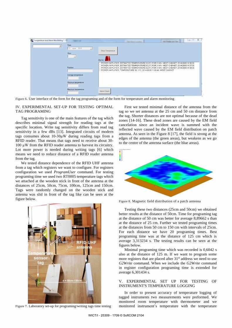
Figure 6. User interface of the form for the tag programing and of the form for temperature and alarm monitoring
IV. EXPERIMENTAL SET-UP FOR TESTING OPTIMAL
TAG PROGRAMING
Tag sensitivity is one of the main features of the tag which
describes minimal signal strength for reading tags at the
specific location. Write tag sensitivity differs from read tag
sensitivity in a few dBs [13]. Integrated circuits of modern
tags consumes about 10-30µW during reading tags from a
RFID reader. That means that tags need to receive about 30-
100 µW from the RFID reader antenna to harvest its circuitry.
Lot more power is needed during writing tags [6] which
means we need to reduce distance of a RFID reader antenna
from the tag.
We tested distance dependence of the RFID UHF antenna
from a tag which registers we want to configure. For registers
configuration we used ProgramUser command. For testing
programing time we used two RT0005 temperature tags which
we attached at the wooden stick in front of the antenna at the
distances of 25cm, 50cm, 75cm, 100cm, 125cm and 150cm.
Tags were randomly changed on the wooden stick and
antenna was slid in front of the tag like can be seen at the
figure below.
Figure 7. Laboratory set-up for programing/writing tags time testing
First we tested minimal distance of the antenna from the
tag so we set antenna at the 25 cm and 50 cm distance from
the tag. Shorter distances are not optimal because of the dead
zones [14-16]. These dead zones are caused by the EM field
cancelation since an incident wave is summed with the
reflected wave caused by the EM field distribution on patch
antenna. As seen in the Figure 8 [17], the field is strong at the
edges of the antenna (the green areas), but weakens as we go
to the centre of the antenna surface (the blue areas).
Figure 8. Magnetic field distribution of a patch antenna
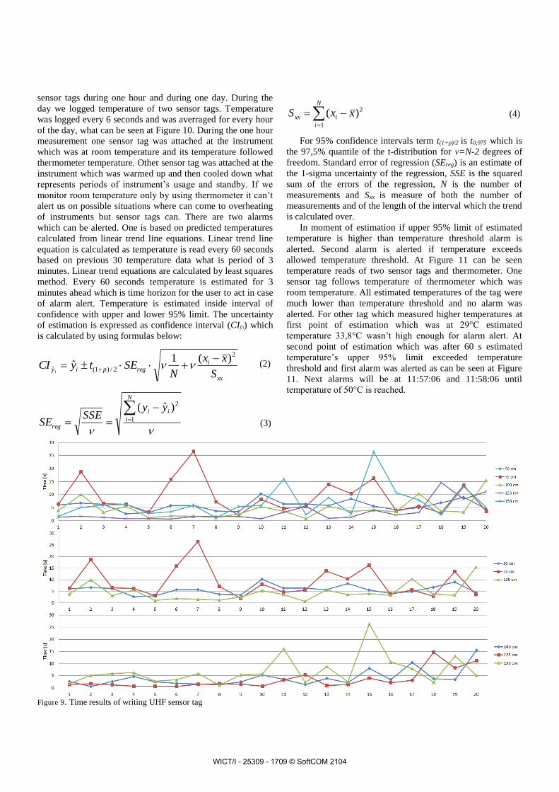
Testing these two distances (25cm and 50cm) we obtained
better results at the distance of 50cm. Time for programing tag
at the distance of 50 cm was better for average 8,89662 s than
at the distance of 25 cm. Further we tested programing times
at the distances from 50 cm to 150 cm with intervals of 25cm.
For each distance we have 20 programing times. Best
programing time was at the distance of 125 cm which is
average 3,313234 s. The testing results can be seen at the
figures below.
Minimal programing time which was recorded is 0,6042 s
also at the distance of 125 m. If we want to program some
more registers that are placed after 31st address we need to use
G2Write command. When we include the G2Write command
in register configuration programing time is extended for
average 6,301434 s.
V. EXPERIMENTAL SET UP FOR TESTING OF
INSTRUMENT'S TEMPERATURE LOGGING
In order to present accuracy of temperature logging of
tagged instruments two measurements were preformed. We
monitored room temperature with thermometer and we
monitored instrument’s temperature with the temperature
WICT/I - 25309 - 1709 © SoftCOM 2104
sensor tags during one hour and during one day. During the
day we logged temperature of two sensor tags. Temperature
was logged every 6 seconds and was averraged for every hour
of the day, what can be seen at Figure 10. During the one hour
measurement one sensor tag was attached at the instrument
which was at room temperature and its temperature followed
thermometer temperature. Other sensor tag was attached at the
instrument which was warmed up and then cooled down what
represents periods of instrument’s usage and standby. If we
monitor room temperature only by using thermometer it can’t
alert us on possible situations where can come to overheating
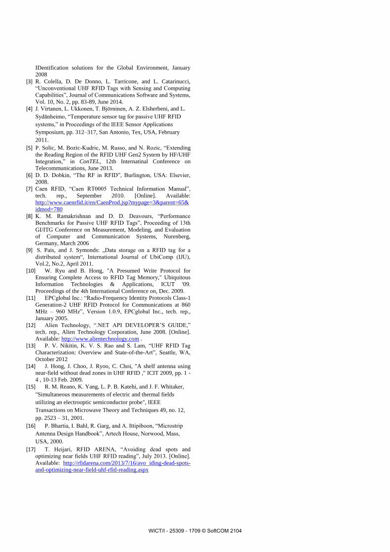
of instruments but sensor tags can. There are two alarms
which can be alerted. One is based on predicted temperatures
calculated from linear trend line equations. Linear trend line
equation is calculated as temperature is read every 60 seconds
based on previous 30 temperature data what is period of 3
minutes. Linear trend equations are calculated by least squares
method. Every 60 seconds temperature is estimated for 3
minutes ahead which is time horizon for the user to act in case
of alarm alert. Temperature is estimated inside interval of
confidence with upper and lower 95% limit. The uncertainty
of estimation is expressed as confidence interval (CIŷi) which
is calculated by using formulas below:
xx
iregpiy
S
xx
NSEtyCI
i
2
2/)1(ˆ
)(1ˆ
(2)
N
i
ii
reg
yySSE
SE 1
2)ˆ(
(3)
N
i
ixx xxS1
2)( (4)
For 95% confidence intervals term t(1+p)/2 is t0,975 which is
the 97,5% quantile of the t-distribution for ν=N-2 degrees of
freedom. Standard error of regression (SEreg) is an estimate of
the 1-sigma uncertainty of the regression, SSE is the squared
sum of the errors of the regression, N is the number of
measurements and Sxx is measure of both the number of
measurements and of the length of the interval which the trend
is calculated over.
In moment of estimation if upper 95% limit of estimated
temperature is higher than temperature threshold alarm is
alerted. Second alarm is alerted if temperature exceeds
allowed temperature threshold. At Figure 11 can be seen
temperature reads of two sensor tags and thermometer. One
sensor tag follows temperature of thermometer which was
room temperature. All estimated temperatures of the tag were
much lower than temperature threshold and no alarm was
alerted. For other tag which measured higher temperatures at
first point of estimation which was at 29°C estimated
temperature 33,8°C wasn’t high enough for alarm alert. At
second point of estimation which was after 60 s estimated
temperature’s upper 95% limit exceeded temperature
threshold and first alarm was alerted as can be seen at Figure
11. Next alarms will be at 11:57:06 and 11:58:06 until
temperature of 50°C is reached.
Figure 9. Time results of writing UHF sensor tag
WICT/I - 25309 - 1709 © SoftCOM 2104
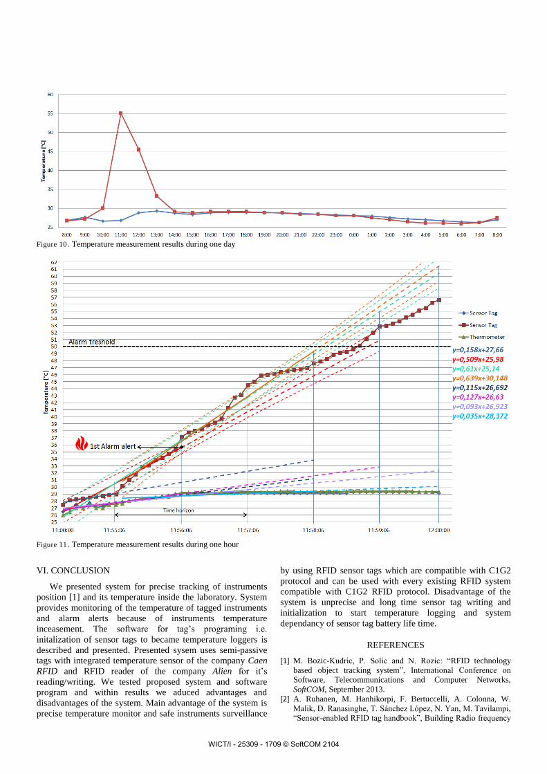
Figure 10. Temperature measurement results during one day
Figure 11. Temperature measurement results during one hour
VI. CONCLUSION
We presented system for precise tracking of instruments
position [1] and its temperature inside the laboratory. System
provides monitoring of the temperature of tagged instruments
and alarm alerts because of instruments temperature
inceasement. The software for tag’s programing i.e.
initalization of sensor tags to became temperature loggers is
described and presented. Presented sysem uses semi-passive
tags with integrated temperature sensor of the company Caen
RFID and RFID reader of the company Alien for it’s
reading/writing. We tested proposed system and software
program and within results we aduced advantages and
disadvantages of the system. Main advantage of the system is
precise temperature monitor and safe instruments surveillance
by using RFID sensor tags which are compatible with C1G2
protocol and can be used with every existing RFID system
compatible with C1G2 RFID protocol. Disadvantage of the
system is unprecise and long time sensor tag writing and
initialization to start temperature logging and system
dependancy of sensor tag battery life time.
REFERENCES
[1] M. Bozic-Kudric, P. Solic and N. Rozic: “RFID technology
based object tracking system”, International Conference on
Software, Telecommunications and Computer Networks,
SoftCOM, September 2013.
[2] A. Ruhanen, M. Hanhikorpi, F. Bertuccelli, A. Colonna, W.
Malik, D. Ranasinghe, T. Sánchez López, N. Yan, M. Tavilampi,
“Sensor-enabled RFID tag handbook”, Building Radio frequency
WICT/I - 25309 - 1709 © SoftCOM 2104
IDentification solutions for the Global Environment, January
2008
[3] R. Colella, D. De Donno, L. Tarricone, and L. Catarinucci,
“Unconventional UHF RFID Tags with Sensing and Computing
Capabilities”, Journal of Communications Software and Systems,
Vol. 10, No. 2, pp. 83-89, June 2014.
[4] J. Virtanen, L. Ukkonen, T. Björninen, A. Z. Elsherbeni, and L.
Sydänheimo, “Temperature sensor tag for passive UHF RFID
systems,” in Proceedings of the IEEE Sensor Applications
Symposium, pp. 312–317, San Antonio, Tex, USA, February
2011.
[5] P. Solic, M. Bozic-Kudric, M. Russo, and N. Rozic, “Extending
the Reading Region of the RFID UHF Gen2 System by HF/UHF
Integration,” in ConTEL, 12th Internatinal Conference on
Telecommunications, June 2013.
[6] D. D. Dobkin, “The RF in RFID”, Burlington, USA: Elsevier,
2008.
[7] Caen RFID, “Caen RT0005 Technical Information Manual”,
tech. rep., September 2010. [Online]. Available:
http://www.caenrfid.it/en/CaenProd.jsp?mypage=3&parent=65&
idmod=780
[8] K. M. Ramakrishnan and D. D. Deavours, “Performance
Benchmarks for Passive UHF RFID Tags”, Proceeding of 13th
GI/ITG Conference on Measurement, Modeling, and Evaluation
of Computer and Communication Systems, Nurenberg,
Germany, March 2006
[9] S. Pais, and J. Symonds: „Data storage on a RFID tag for a
distributed system“, International Journal of UbiComp (IJU),
Vol.2, No.2, April 2011. [10] W. Ryu and B. Hong, "A Presumed Write Protocol for
Ensuring Complete Access to RFID Tag Memory," Ubiquitous
Information Technologies & Applications, ICUT '09.
Proceedings of the 4th International Conference on, Dec. 2009.
[11] EPCglobal Inc.: “Radio-Frequency Identity Protocols Class-1
Generation-2 UHF RFID Protocol for Communications at 860
MHz – 960 MHz”, Version 1.0.9, EPCglobal Inc., tech. rep.,
January 2005.
[12] Alien Technology, “.NET API DEVELOPER’S GUIDE,”
tech. rep., Alien Technology Corporation, June 2008. [Online].
Available: http://www.alientechnology.com .
[13] P. V. Nikitin, K. V. S. Rao and S. Lam, “UHF RFID Tag
Characterization: Overview and State-of-the-Art”, Seattle, WA,
October 2012
[14] J. Hong, J. Choo, J. Ryoo, C. Choi, "A shelf antenna using
near-field without dead zones in UHF RFID ," ICIT 2009, pp. 1 -
4 , 10-13 Feb. 2009.
[15] R. M. Reano, K. Yang, L. P. B. Katehi, and J. F. Whitaker,
"Simultaneous measurements of electric and thermal fields
utilizing an electrooptic semiconductor probe", IEEE
Transactions on Microwave Theory and Techniques 49, no. 12,
pp. 2523 – 31, 2001.
[16] P. Bhartia, I. Bahl, R. Garg, and A. Ittipiboon, “Microstrip
Antenna Design Handbook”, Artech House, Norwood, Mass,
USA, 2000.
[17] T. Heijari, RFID ARENA, “Avoiding dead spots and
optimizing near fields UHF RFID reading”, July 2013. [Online].
Available: http://rfidarena.com/2013/7/16/avo iding-dead-spots-
and-optimizing-near-field-uhf-rfid-reading.aspx
WICT/I - 25309 - 1709 © SoftCOM 2104