RFID (Radio Frequency Identification) Overview · RFID (Radio Frequency Identification) Overview...
56
RFID (Radio Frequency Identification) Overview António Grilo Courtesy: Greg Leeming, INTEL Sridhar Iyer, ITT Bombay
Transcript of RFID (Radio Frequency Identification) Overview · RFID (Radio Frequency Identification) Overview...

RFID (Radio Frequency Identification)Overview
António Grilo
Courtesy: Greg Leeming, INTEL
Sridhar Iyer, ITT Bombay

2
Radio Frequency Identification
Tags
Reader
Power from RF field
ReaderAntenna
Reader->Tag Commands
Tag->Reader Responses
RFID Communication Channel

RFID Communications
Host manages Reader(s) and issues Commands Reader and tag communicate via RF signal Carrier signal generated by the reader Carrier signal sent out through the antennas Carrier signal hits tag(s) Tag receives and modifies carrier signal
“sends back” modulated signal (Passive Backscatter – also referred to as “field disturbance device”)
Antennas receive the modulated signal and send them to the Reader
Reader decodes the data Results returned to the host application
3
4
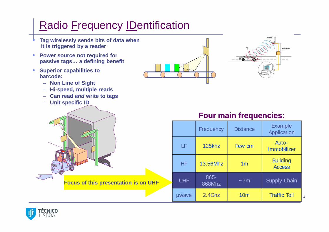
Radio Frequency IDentification
Frequency Distance Example Application
LF 125khz Few cm Auto-Immobilizer
HF 13.56Mhz 1m Building Access
UHF 865-868Mhz ~7m Supply Chain
μwave 2.4Ghz 10m Traffic Toll
Four main frequencies:Four main frequencies:
• Tag wirelessly sends bits of data whenit is triggered by a reader
• Power source not required for passive tags… a defining benefit
• Superior capabilities to barcode:
– Non Line of Sight– Hi-speed, multiple reads– Can read and write to tags– Unit specific ID
Focus of this presentation is on UHF
RFID History
First Bar code patents – 1930s First use of RFID device – 2nd world war – Brittan used RFID-like
technology for Identify- Friend or Foe Harry Stockman October 1948 Paper – Communication by means of
reflected power ( The proceedings of the Institute of Radio Engineers) First RFID Patent - 1973 Auto-ID center founded at MIT – 1999
Standardization effort taken over by EPC Global (Electronic Product Code)
Current thrust primarily driven by Wal-Mart and DoD Automate Distribution:
Reduce cost (man power, shipping mistakes) Increase sales (keep shelves full) DoD Total Asset Visibility Initiative
5
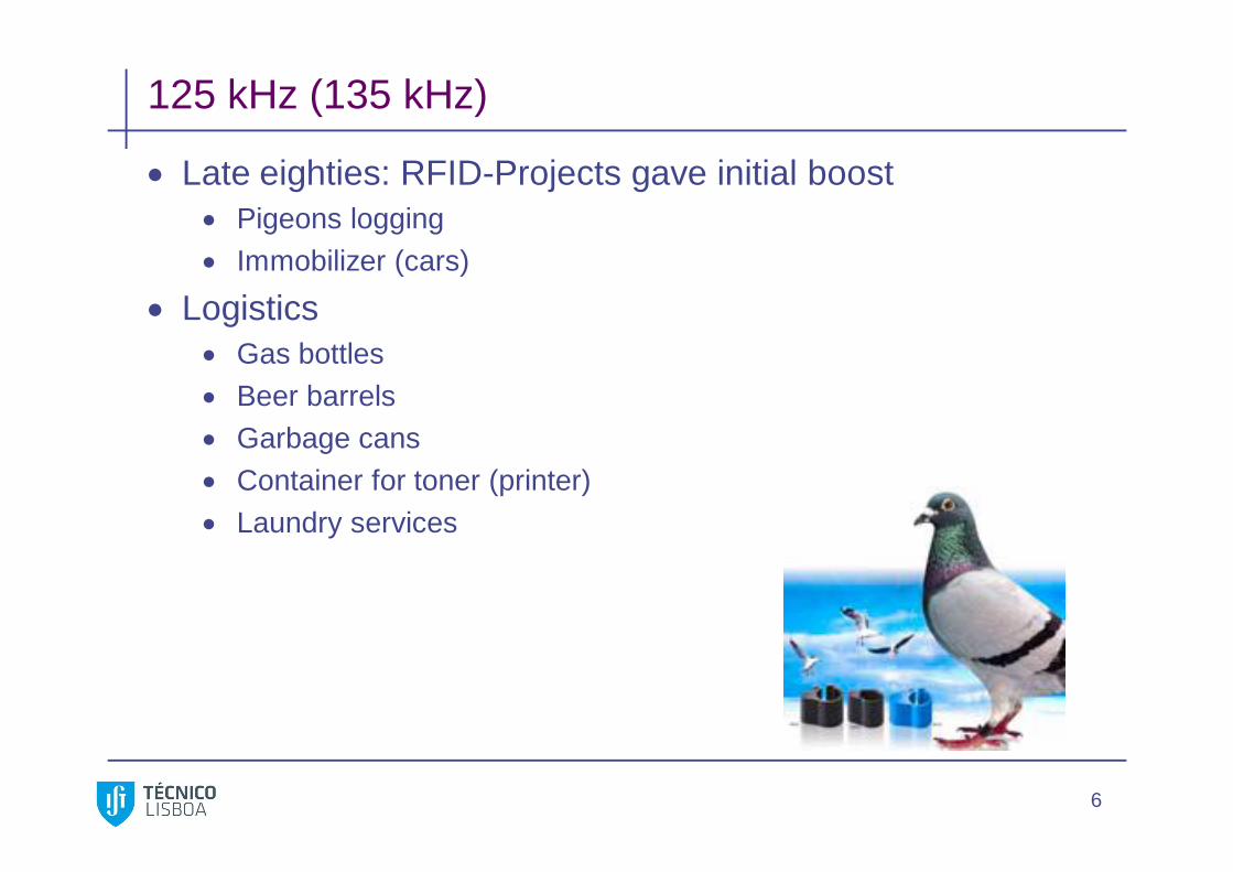
125 kHz (135 kHz)
Late eighties: RFID-Projects gave initial boost Pigeons logging Immobilizer (cars)
Logistics Gas bottles Beer barrels Garbage cans Container for toner (printer) Laundry services
6
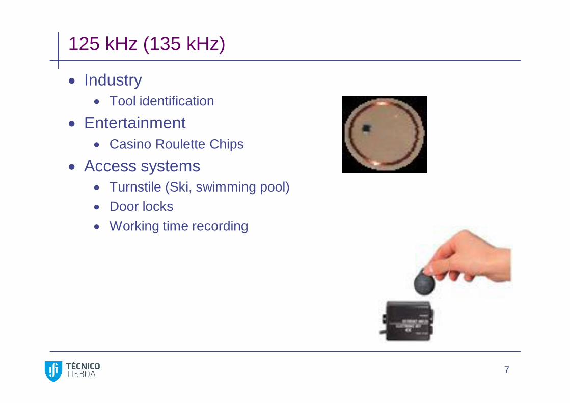
125 kHz (135 kHz)
Industry Tool identification
Entertainment Casino Roulette Chips
Access systems Turnstile (Ski, swimming pool) Door locks Working time recording
7

13,56 MHz
Late nineties: Encryption and faster Payment systems
Cafeteria, restaurants
Access systems / Events Turnstile, Door locks Stadium, Theme parks Convention center (Mifare)
Public transportation Bus, underground, ferries (South Korea, London)
8

868 MHz (UHF)
Late nineties: Projects for UHF systems Logistics
First projects had a poor hit rate (60%) Expensive labels
National Identity ID card (China 1300Mio, 2005/6) License-plate number (50cm reading distance)
9

Basic Tag Operational Principles
• Near field (LF, HF): inductive coupling of tag to magnetic field circulating around antenna (like a transformer)• Varying magnetic flux induces current in tag. Modulate tag load to communicate with reader• Power decreases proportionally to 1/d6
• Far field (UHF, microwave): backscatter. • Modulate back scatter by changing antenna impedance• Power decreases proportionally to 1/d2
• Boundray between near and far field: d = wavelength / (2 pi) so, once have reached far field, lower frequencies will have lost significantly more energy than high frequencies
• Absorption by non-conductive materials significant problem for microwave frequencies
10

Limiting Factors for Passive RFID
1. Reader transmitter power Pt(reader) (Gov’t. limited)2. Reader receiver sensitivity Sr3. Reader antenna gain Gr (Gov’t. limited)
4. Tag antenna gain Gt (Size limited)5. Power required at tag Pr(tag) (Silicon process limited)6. Tag modulator efficiency Et
11
Implications
Since in far field Pr(tag) 1/d2 , doubling read range requires 4X the transmitter power.
Larger antennas can help, but at the expense of larger physical size because G{t,r} Area.
More advanced CMOS process technology will help by reducing Pr(tag).
At large distances, reader sensitivity limitations dominate.
12
Types of Tags
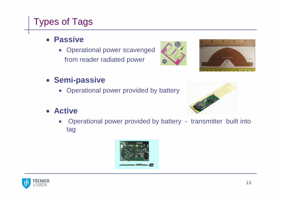
Passive Operational power scavenged
from reader radiated power
Semi-passive Operational power provided by battery
Active Operational power provided by battery - transmitter built into
tag
13

Electronic Product Code
Header - Tag version numberEPC Manager - Manufacturer ID
Object class - Manufacturer’s product IDSerial Number - Unit ID
With 96 bit code, 268 million companies can each categorize 16 million different products where each product category contains up to 687 billion individual units
Note: 64 bit versions also defined, 256 bit version under definition
14

Generic Tag Architecture (Highly Simplified)
15
ProtocolEngine
Receiver
Memory
Ante
nna
Write Path
D
S
G

Possible UHF Reader RF Processor
Transmit path Receive Path Frequency Synthesizer Digital
RFID READERRF ModuleDAC
Hos
t Dev
ice
ADC
Crystal
Micro-Controller
AGC Filters I/QDemod
PLL
VCO
DAC Power Control
PA
Filter Coupler
Coupler
PowerDetect
Coupler
FPGA
Regulation
Baseband&
Protocol
16

Possible Digital Back End
Ethernet
IXP425Processor
Power Supply
RAM
Flash
RF Board Interface
GPIO
Serial Port
LEDsRF
Module
17

Possible Reader Software Stack
RFID Reader API Library
CustomApplication/
Protocol
ReaderProtocol
ApplicationN
etw
ork
man
agem
ent
File Systems
NetworkProtocols
High-Level Interfaces
Low-Level InterfacesO/S
Hardware
Platform API Libraries
CustomApplication/
Protocol
CustomApplication/
Protocol
Network Interface
18
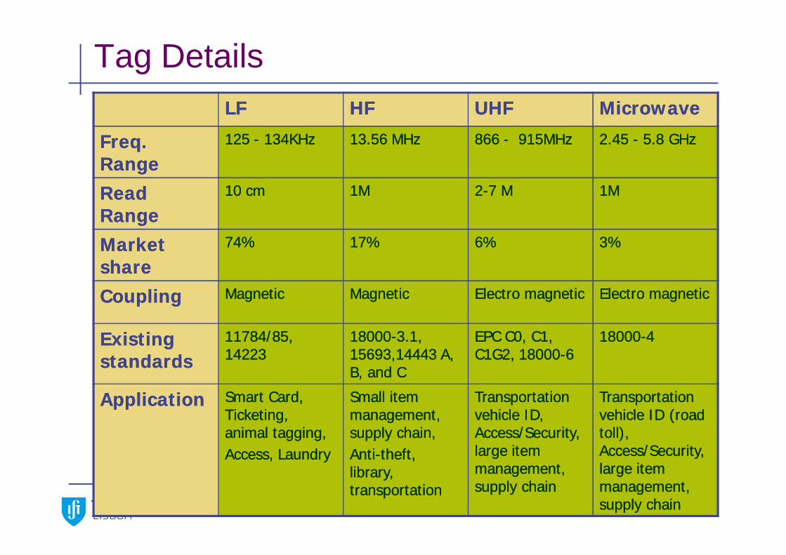
Tag DetailsLFLF HFHF UHFUHF MicrowaveMicrowave
Freq. Freq. RangeRange
125 125 -- 134KHz134KHz 13.56 MHz13.56 MHz 866 866 -- 915MHz915MHz 2.45 2.45 -- 5.8 GHz5.8 GHz
Read Read RangeRange
10 cm10 cm 1M1M 22--7 M7 M 1M1M
Market Market shareshare
74%74% 17%17% 6%6% 3%3%
CouplingCoupling MagneticMagnetic MagneticMagnetic Electro magneticElectro magnetic Electro magneticElectro magnetic
Existing Existing standardsstandards
11784/85, 11784/85, 1422314223
1800018000--3.1, 3.1, 15693,14443 A, 15693,14443 A, B, and CB, and C
EPC C0, C1, EPC C0, C1, C1G2, 18000C1G2, 18000--66
1800018000--44
ApplicationApplication Smart Card, Smart Card, Ticketing, Ticketing, animal tagging,animal tagging,Access, LaundryAccess, Laundry
Small item Small item management, management, supply chain,supply chain,AntiAnti--theft, theft, library, library, transportationtransportation
Transportation Transportation vehicle ID, vehicle ID, Access/Security, Access/Security, large item large item management, management, supply chainsupply chain
Transportation Transportation vehicle ID (road vehicle ID (road toll), toll), Access/Security, Access/Security, large item large item management, management, supply chainsupply chain

Communication Protocols
20
865MHz 867MHz200KHz
Transmission from other ReadersMax 4 sec TX then re-listen for 100 msec
Listen before talk Mandatory listen time of >5 msec before each transmission

ETSI EN 302 208 standard
Shared operation in band 865.0 – 868.0 MHz at transmit powers upto 2 W ERP. Operation in 10 sub-bands of 200 kHz. Power levels of 100 mW, 500 mW and 2 W ERP.
Mandatory “listen before talk” and “look before leap”.
21
865.7 MHz 867.5 MHz
FT
865.1 MHz 867.9 MHz
100 mW
867.7 MHz865.5 MHz
LT
FT
LT LT
FT
600 kHz 600 kHz600 kHz
2 W
FT
LT
500 mW
865.0 MHz 865.6 MHz 867.6 MHz 868.0 MHz

Reader Collision Problem
Reader-Reader Interference Reader-Tag Interference
22

Reader Collision and Hidden Terminal
The passive tags are not able to take part in the collision resolution or avoidance, as in other wireless systems
Consider: RTS-CTS for hidden terminal problem in 802.11 rfid: T is not able to send a CTS in response
23
In case multiple readers try to read the same tag, the tag cannot respond selectively to a particular reader

TDMA Based Solution
Assign different time slots and/or frequencies to nearby readers Reduces to graph coloring problem (readers form vertices)
Only reader to reader interference Assign different operating frequencies
Only multiple reader to tag interference Assign different time slots for operation
Both types of interference First allot different time slots, then frequencies
24
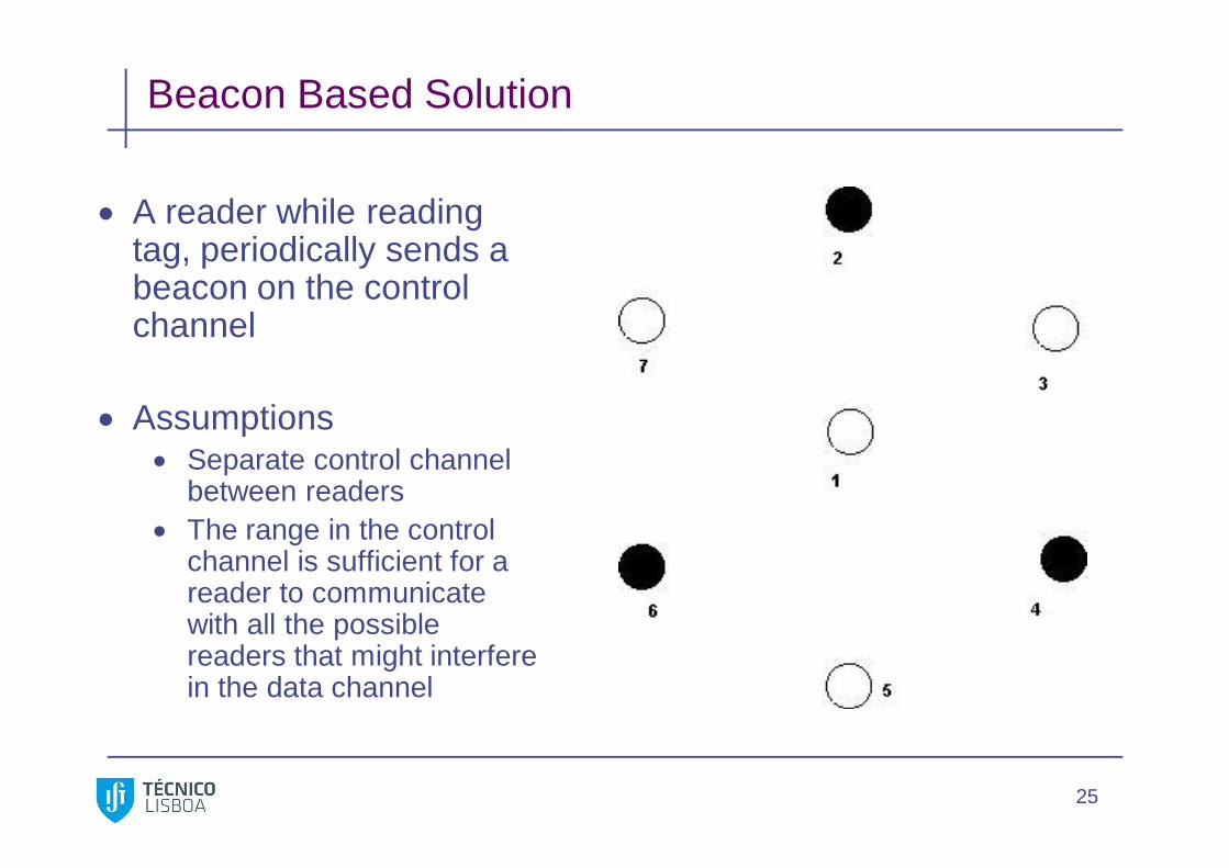
Beacon Based Solution
25
A reader while reading tag, periodically sends a beacon on the control channel
Assumptions Separate control channel
between readers The range in the control
channel is sufficient for a reader to communicate with all the possible readers that might interfere in the data channel

Beacon Based Solution (contd.)
26

Multiple Tags
When multiple tags are in range of the reader: All the tags will be excited at the same time. Makes it very difficult to distinguish between the tags.
Collision avoidance mechanisms: Probabilistic:
Tags return at random times.
Deterministic: Reader searches for specific tags.
27

Tag Collision Problem
Multiple tags simultaneously respond to query Results in collision at the reader
Several approaches Tree algorithm Memoryless protocol Contactless protocol I-code protocol
28

Tree Algorithm
Reader queries for tags Reader informs in case of collision and tags generates 0 or 1
randomly If 0 then tag retransmits on next query If 1 then tag becomes silent and starts incrementing its counter
(which is initially zero) Counter incremented every time collision reported and
decremented every time identification reported Tag remains silent till its counter becomes zero
29

Tree Algorithm – Example
30
Reader informs tags in case of collision and tags generate 0 or 1•If 0 then tag retransmits on next query, else tag becomes silent and starts a counter.
Counter incremented every time collision reported and decremented otherwise.
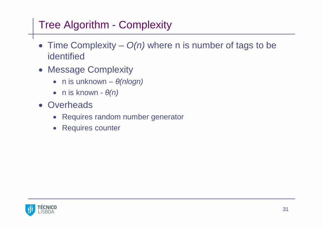
Tree Algorithm - Complexity
Time Complexity – O(n) where n is number of tags to be identified
Message Complexity n is unknown – θ(nlogn) n is known - θ(n)
Overheads Requires random number generator Requires counter
31

Memoryless Protocol
Assumption: tagID stored in k bit binary string Algorithm
Reader queries for prefix p In case of collision queries for p0 or p1
Time complexity Running time – O(n) Worst Case – n*(k + 2 – logn)
Message Complexity – k*(2.21logn + 4.19)
32

Memoryless Protocol – Example
33
Reader queries for prefix p In case of collision, reader queries for p0 or p1 Example: consider tags with prefixes: 00111, 01010, 01100, 10101,
10110 and 10111

Contactless Protocol
Assumption: tagID stored in k bit binary string Algorithm
Reader queries for (i)th bit Reader informs in case of collision
Tags with (i)th bit 0 become silent and maintain counter Tags with (i)th bit 1 respond to next query for (i+1)th bit
Time complexity – O(2k) Message complexity – O(m(k+1)), where m is number of
tags
34

Contactless Protocol – Example
35
Reader queries for (i)th bit Reader informs in case of collision
Tags with (i)th bit 0 become silent and maintain counter Tags with (i)th bit 1 respond to next query for (i+1)th bit
Example: tags with prefixes: 01, 10 and 11

I-Code Protocol
Based on slotted ALOHA principle Algorithm
Reader provides time frame with N slots, N calculated for estimate n of tags
Tags randomly choose a slot and transmit their information Responses possible for each slot are
Empty, no tag transmitted in this slot – c0
Single response, identifying the tag – c1
Multiple responses, collision – ck
36

I-Code Protocol
37
New estimate for n : lower bound εlb(N, c0, c1,ck) = c1 + 2ck
Using estimate n, N calculated N becomes constant after some time Using this N calculate number of read cycles s to identify tags
with a given level of accuracy α
Time complexity – t0*(s+p) t0 is time for one read cycle p number of read cycles for estimating N
Message complexity – n*(s+p)

ISO 18000 Standard
18000-1 Reference architecture and definition of parameters 18000-2 Parameters for air interface communications below 135 kHz 18000-3 Parameters for air interface communications at 13,56 MHz 18000-4 Parameters for air interface communications at 2,45 GHz (18000-5) Parameters for air interface communications at 5,8 GHz 18000-6 (Type A, B, C) Parameters for air interface communications at
860-960 MHz 18000-7 Parameters for active air interface communications at 433
MHz
38

EPCglobal Tag Classes
Class-1: Identity Tags
Class-2: Higher functionality tags
Class-3: Battery-Assisted Passive Tags
Class-4: Active Tags
39

Competing UHF Protocols (EPC only)Read Rate Read or
Read/WriteTagCost
Privacy Security Global Standard
Class 0 NA: 800 reads/secEU: 200 reads/sec
Read Only $$ 24 bit password
Reader broadcasts OID or Anonymous modes with reduced
throughput
No
Class 0+ NA:800 reads/secEU:200 reads/sec
Read & Write $$ See above See above No
Class 1 NA:200 reads/secEU: 50 reads/sec
Read & Write $ 8 bit password Reader broadcasts partial OID
No
Class 1 Gen 2(UHF Gen2)
NA:1700 reads/secEU: 600 reads/sec
Read & Write ? 32 bit password and concealed mode
Authentication and Encryption
Yes
40

Class 0 Protocol
41
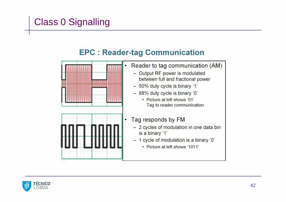
Class 0 Signalling
42

Default Class 0 Reader Communication Sequence Tag Singulation ProcessTag power up, reset, and calibration process
Single Binary Transversal
Repeated after each frequency hop
Once tag has been singulated, reader can send commands to it or begin next BT cycle
Reset: 800 micro sec uninterrupted continuous waveOscillator calibration: 8 116 micro sec pulses
Data calibration: 3 pulses ( data “0”, data “1”, data “null”)
Reset: 800 micro sec uninterrupted continuous waveOscillator calibration: 8 116 micro sec pulses
Data calibration: 3 pulses ( data “0”, data “1”, data “null”)
Readerpower up
43
Tag Singulation Processread individual tag from group of all tags in range of reader
Basic process:
1. All tags within range of reader backscatter their MSB to the reader.
2. Reader responds with either a 1 or a 0.
3. If tag bit equals reader bit, tag backscatters the next bit in it’s code . If instead, tag bit does not equal reader bit, tag goes mute for remainder of singulation.
4. Process continues until reader has completely read a single tag.
5. Reader conducts consecutive singulations until all tags in its range are read.
6. Reader can interrupt the singulation process to send commands to a single tag, a subset of all tags in range, or globally to all tags in range.
44

EPC Gen 2 Protocol
EPC Gen 2 is a UHF protocol EPC Gen 2 Protocol is likely to become a global standard Gen 2 protocol was designed to optimize performance in
different regulatory environments around the world
45
EPC Gen 2 Protocol
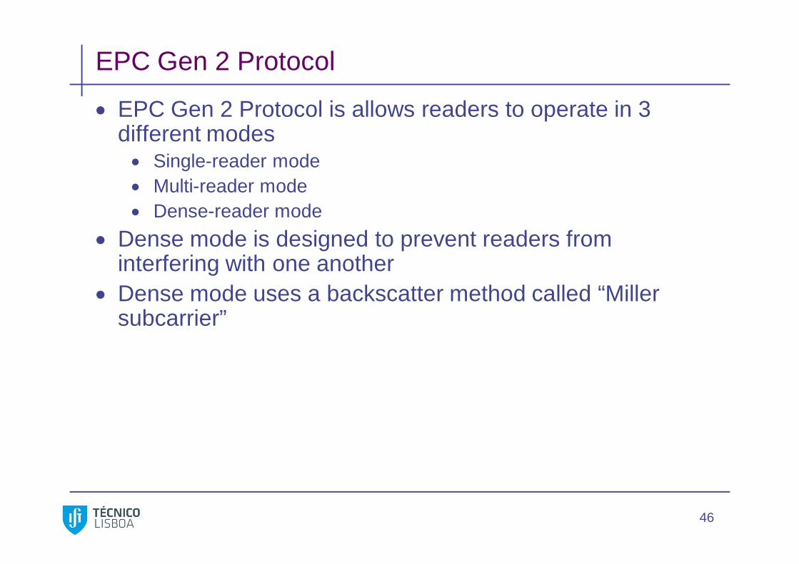
EPC Gen 2 Protocol is allows readers to operate in 3 different modes Single-reader mode Multi-reader mode Dense-reader mode
Dense mode is designed to prevent readers from interfering with one another
Dense mode uses a backscatter method called “Miller subcarrier”
46

EPC Gen 2 Protocol - Memory
Gen 2 tags are field programmable Gen 2 tags have 4 memory areas:
3 required: EPC Password Tag identification
1 optional Memory areas can be locked temporary or permanently
47

EPC Gen 2 Protocol – Q Algorithm Q Algorithm allows readers to query tags even if two tags
have the same EPC or do not contain EPC at all The query mechanism is based on random number
generation The reader does not have to transmit EPC, preventing
eavesdropping
48

Sessions
Each Gen 2 tags can have 4 separate sessions for communicating
Sessions is a means for preventing interference (e.g. caused by different readers)
49
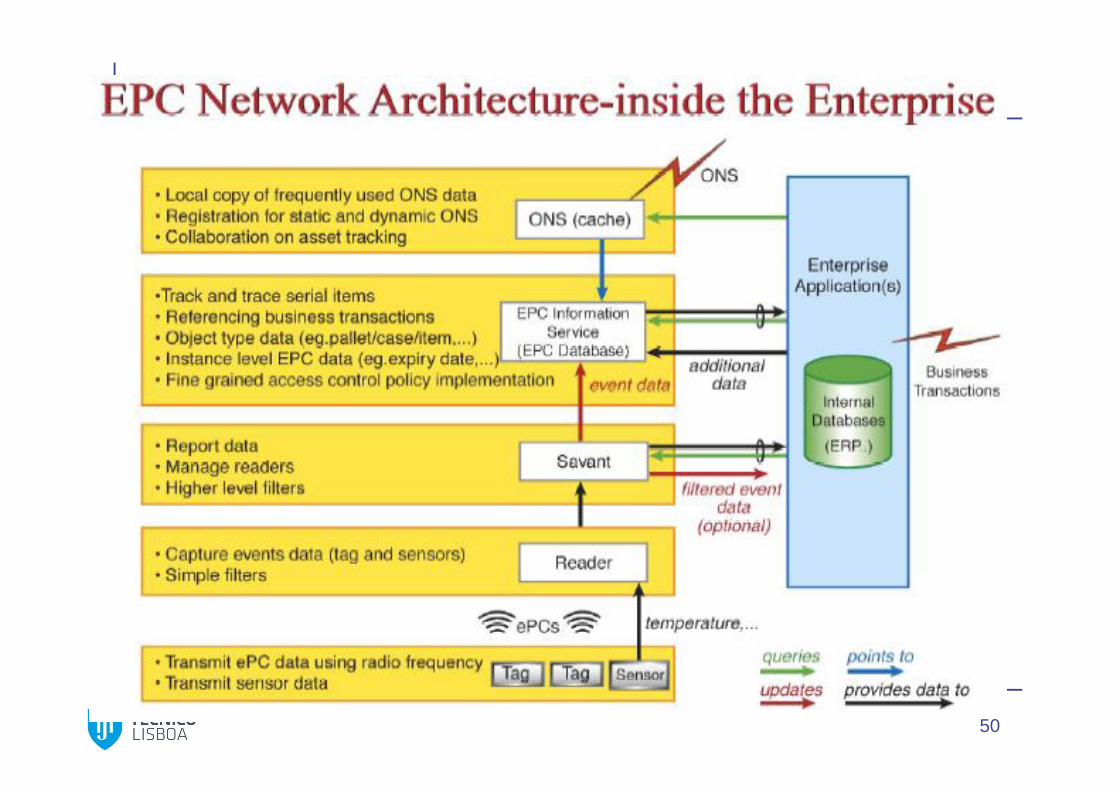
50

51
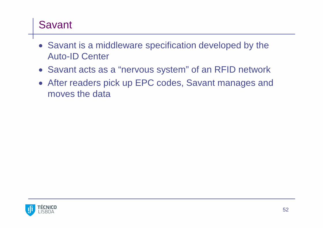
Savant
Savant is a middleware specification developed by the Auto-ID Center
Savant acts as a “nervous system” of an RFID network After readers pick up EPC codes, Savant manages and
moves the data
52

Savant
Savant uses distributed architecture and is organized into a hierarchy of individual savants that manages the process of gathering and distributing data
Tasks savant can do: Data smoothing Reader coordination Data forwarding Data storage Task Management
53

Object Name Service (ONS) The Object Name Service (ONS) provides a global lookup
service to translate an EPC into one or more Internet Uniform Reference Locators (URLs) where further information on the object may be found
These URLs often identify an EPC Information Service, though ONS may also be used to associate EPCs with web sites and other Internet resources relevant to an object
ONS provides both static and dynamic services. Static ONS typically provides URLs for information maintained by an object’s manufacturer
Dynamic ONS services record a sequence of custodians as an object moves through a supply chain
ONS is built using the same technology as DNS, the Domain Name Service of the Internet
Source: Auto-ID/EPCglobal 54
Physical Markup Language (PML) The Physical Mark-Up Language (PML) is a collection of
common, standardized XML vocabularies to represent and distribute information related to EPC Network enabled objects
The PML standardizes the content of messages exchanged within the EPC network.
It is a part of the Auto-ID Center’s effort to develop standardized 283
interfaces and protocols for the communication with and within the Auto-ID infrastructure
The core part of the physical mark-up-language (PML Core) provides a standardized format for the exchange of the data captured by the sensors (readers) in the Auto-ID infrastructure
55
Reader Protocol
The Reader Protocol specifies the interaction between a device capable of reading (and possibly writing) tags, and application software
56