RFE1600 Series Datasheet - TDK
4
RFE1600 Series 1600W 1U Industrial Power Supplies RFE1600 Series 1 Features Benefits The RFE1600 AC-DC industrial power supplies are high efficiency and are 1U in height. They have internal ORing MOSFETs and current share for parallel operation. Communication is possible with the power supplies using the optional isolated PMBus™ (I 2 C) interface. AC fail, DC good, remote output adjust, remote on/off and a 12V auxiliary output are fitted as standard. • Internal ORing MOSFET and Current Share • Up to 1600W in 1U Height • Full Array of Signals Available • PMBus TM (I 2 C) and LAN options • Analog Output Adjustment • Suitable For N+1 Redundancy • Utilizes Less System Space • Easy Remote Monitoring • Industry Standard Communication Interfaces • Simple External Resistance or Voltage Connection https://product.tdk.com/en/power/rfe www.emea.lambda.tdk.com/uk/products/rfe Model Selector Model Output Adjustment Max Current (A) Max Power (W) Max Current (A) Max Power (W) Voltage (V) Range (V) (1) (Vin>170Vac) (Vin>170Vac) (100<Vin<170Vac) (2) (100<Vin<170Vac) (2) RFE1600-12 12 9.6 - 13.2 133 1596 100 1200 RFE1600-24 24 19.2 - 29 67 1608 50 1200 RFE1600-32 32 25.6 - 38.4 47 1504 37.5 1200 RFE1600-48 48 38.4 - 58 33 1584 25 1200 RFE1600- 12 / S Output voltage 12, 24, 32, 48 blank No PMBus™ / I 2 C S PMBus™ / I 2 C interface
Transcript of RFE1600 Series Datasheet - TDK
RFE1600 Series1600W 1U Industrial Power Supplies
RFE1600 Series 1
Features Benefits
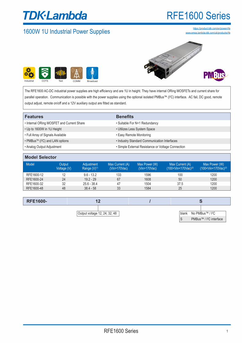
The RFE1600 AC-DC industrial power supplies are high efficiency and are 1U in height. They have internal ORing MOSFETs and current share forparallel operation. Communication is possible with the power supplies using the optional isolated PMBus™ (I2C) interface. AC fail, DC good, remote output adjust, remote on/off and a 12V auxiliary output are fitted as standard.
• Internal ORing MOSFET and Current Share• Up to 1600W in 1U Height• Full Array of Signals Available• PMBusTM (I2C) and LAN options• Analog Output Adjustment
• Suitable For N+1 Redundancy• Utilizes Less System Space• Easy Remote Monitoring• Industry Standard Communication Interfaces• Simple External Resistance or Voltage Connection
https://product.tdk.com/en/power/rfewww.emea.lambda.tdk.com/uk/products/rfe
Model Selector Model Output Adjustment Max Current (A) Max Power (W) Max Current (A) Max Power (W) Voltage (V) Range (V)(1) (Vin>170Vac) (Vin>170Vac) (100<Vin<170Vac)(2) (100<Vin<170Vac)(2)
RFE1600-12 12 9.6 - 13.2 133 1596 100 1200 RFE1600-24 24 19.2 - 29 67 1608 50 1200 RFE1600-32 32 25.6 - 38.4 47 1504 37.5 1200 RFE1600-48 48 38.4 - 58 33 1584 25 1200
RFE1600- 12 / S
Output voltage 12, 24, 32, 48 blank No PMBus™ / I2CS PMBus™ / I2C interface

RFE1600 Series2
Specifications
Specifications
Model RFE1600-12 RFE1600-24 RFE1600-32 RFE1600-48 Input Input Voltage range Vac 85 - 265 Input Frequency Hz 47 - 63 Input Current (115/230Vac) A 11.6 / 8.1 Inrush Current A <35 Leakage Current mA Less than 0.75/1.5 at 115/230Vac Power Factor Correction - Meets EN61000-3-2, PF>0.98 at full load Harmonic Compliance - Meets IEC61000-3-2 Hold Up Time ms >10ms, 100/230Vac Input, 80% loading Efficiency % 87 / 90 88 / 90 88 / 90 89 / 92 Conducted & Radiated EMI - EN55032 & FCC part 15; Conducted class B, Radiated class A Immunity - See immunity section Safety Certifications and Markings - IEC/UL/CSA/EN62368-1, 60950-1, CE Mark and UKCA Mark
Model RFE1600-12 RFE1600-24 RFE1600-32 RFE1600-48 Output Line Regulation mV 30 60 80 120 Load Regulation mV 60 120 160 240 External Load Capacitance uF/A 1000 Ripple & Noise mV 240 240 320 480 Temperature Coefficient %/°C <0.02 Minimum Load - No minimum load required Overcurrent Protection % 105-115 (Programmable) Overvoltage Protection (1) % 110% (Tracking). Cycle AC to reset or utilize Remote On/Off Overtemperature Protection - Shutdown with automatic reset. Warning signal provided (1) Remote Sense Compensation V/wire 0.25V 0.5V 0.75 1.0V Remote On/Off - Yes, inhibit & enable AC Good Signal - Open Collector, ON when AC is within 85-270Vac DC Good Signal - Open Collector, ON when output is above 85 to 95% of setpoint (tracking) Communication - Optional isolated PMBus™ (I2C) interface ( /S suffix) or plug-in LAN module. See model selectors Auxiliary Output - 11.2 - 12.5V, 0.5A, 240mV ripple and noise Indicators - AC OK: Green LED; DC OK / Fail: Green / Red LED Parallel Operation - Yes, single wire current share, 5% accuracy of max current, up to 10 units
Test Standard Test Level Criteria Notes
Radiated Susceptibility EN61000-4-3 2 A - Electrical Fast Transient Burst EN61000-4-4 2 B - Surge EN61000-4-5 3,4 B - Conducted Susceptibility EN61000-4-6 2 A - Magnetic fields EN61000-4-8 4 A - Voltage Dips >95% for 0.5 cycles B - EN61000-4-11 30% for 25/30 cycles C - Interruptions >95% for 250/300 cycles C -
Immunity

RFE1600 Series 3
Specifications Model RFE1600-12 RFE1600-24 RFE1600-32 RFE1600-48 Environnmental Operating Temperature °C -10 to +50: 100% load; +50 to +60 derate: 2%/˚C of load; +60 to +70 derate: 2.5%/˚C of load. For models with reverse air contact factory. Storage Temperature °C -30 to +85 Humidity (non condensing) %RH Operating: 10 - 90, Storage: 10 - 95 Cooling - Internal variable speed fans. Airflow enters from the front. Contact factory for reverse airflow option. Altitude m 3000 max. Derate output current 2%/100m above 2000m. Withstand Voltage (For 1 minute) - Input to Output 3kVac, Input to Ground 2kVac, Output to Ground: 500Vac 500Vac 500Vac 2250Vdc (POE) Isolation Resistance MΩ >100 at 25°C, 70%RH & Output to Ground 500Vdc Vibration (Non-operating) - Meets IEC60068-2-64 (Basic Transportation) Shock (Non-operating) - Meets IEC60068-2-27 (Basic Transportation) Other Weight (Typ) g 1,550 Size (LxWxH) mm 320 x 85 x 40.1 Size (LxWxH) Inches 12.6 x 3.35 x 1.61 PMBusTM / I2C Interface (1) - Isolated from output, Add suffix /S, PMBusTM compatible MTBF - Telcordia Hours 199426 (Estimated based on HFE1600 figures) Warranty Years 3
Notes (1) See installation manual for detailed specifications and test methods (2) Derate linearly 1%/V from 100Vac to 85Vac input
PIN No. FUNCTION1 -SENSE
2 +SENSE
3 VOLTAGE PROGRAMMING
4 CURRENT PROGRAMMING
5 VOLTAGE REFERENCE
6 TEMP. ALARM
7 DC O.K
8 ENABLE
9 SIGNAL RETURN
10 -LOCAL SENSE
11 +LOCAL SENSE
12 TRIMMER
13 +5V
14 -SENSE
15 AC FAIL
16 CURRENT SHARE
17 SIGNAL RETURN
18 AUX_OUT (+12V)
PIN No. FUNCTION1 A0 (PMBus)
2 A1 (PMBus)
3 A2 (PMBus)
4 -SENSE
5 SMB ALERT (PMBus)
6 SDA (PMBus)
7 SCL (PMBus)
8 SIGNAL_RTN
NOTES:1. MOUNTING SCREWS MUST NOT PROTRUDE INTO THE POWER SUPPLY MORE THAN 6.0 mm,2. LED INDICATORS. REFER TO INSTRUCTION MANUAL3. ALLOW MINIMUM 50mm OF UNRESTRICTED AIR SPACE AT THE REAR OF THE UNIT. DO NOT OBSTRUCT AIR FLOW TO THE UNIT FRONT PANEL.4. RECEPTACLE SAMTEC P/N IPD1-09-D-K CONTACT PIN SAMTEC CC79L-2024-01-L PROVIDED AS ACCESSORY IN THE PACKAGE HAND TOOL: CAT-HT-179-2024-11 WIRE AWG 20-245. RECEPTACLES SAMTEC P/N IPD1-04-D-K CONTACT PIN SAMTEC CC79L-2024-01-L PROVIDED AS ACCESSORY IN THE PACKAGE FOR “/S” OPTION HAND TOOL: CAT-HT-179-2024-11 WIRE AWG 20-246. MODEL NAME, INPUT AND OUTPUT RATING AND SAFETY APPROVALS SYMBOLS ARE DESCRIBED ON TOP SURFACE OF LABEL7. REAR PANEL CONNECTORS AND BUS BAR POLARITY DESCRIPTION
356.6±1.0
85.0±0.5
30.6±1.0 BUS BAR (+)
10.0TYPDETAIL B
SCALE 2:1J1(SEE NOTE 4)
18
9 1 4 1
10 85
DC OK LED(SEE NOTE 2)
DETAIL ASCALE 1:1
14.5TYP X 2
M3x8 SEMS SCREWFOR SENSE CONNECTIONIN EACH BUS BAR
7.0TYP
J2(SEE NOTE 5)
9.3
9.0±0.5
BUS BAR (-)
B
42.2
GND
NL
21.4
36.5±0.5
28.8
±0.5
70.0
±0.5
6.5
13.0
TYP
16.0±1.0
SEE NOTE 7
SEE NOTE 6
AIR FLOWDIRECTION
9.0A
AA
320.0±1.0
252.0±0.5
264.7±0.5
43.0±0.5
40.5±0.3
MOUNTING HOLES M4MARKED “A”2 HOLES ON EACH SIDE(SEE NOTE 1) MOUNTING HOLES M3
3 PLACES MARKED “B”(SEE NOTE 1)
B
B
B
J1 J2VOUT TRIM
M6 OR 1/4” SCREWS FORLOAD WIRES CONNECTIONFOR EACH BUS BAR
+
2.5
22.8
±0.5
14.3
6.5T
YP
2.5T
YP
x 2
40.8
±0.5
20.4
TYP
36.0
±0.5
Outline Drawing RFE1600

RFE1600_Datasheet_260799 February 9th, 2022 v1
RFE1600 Series4
TDK-Lambda France SAS TDK-Lambda Americas
TDK Electronics do Brasil Ltda
Tel: +33 1 60 12 71 [email protected]/fr
Tel: +55 11 3289-9599sales.br@tdk-electronics.tdk.comwww.tdk-electronics.tdk.com/en
Tel: +1 800-LAMBDA-4 or 1-800-526-2324powersolutions@us.tdk-lambda.comwww.us.lambda.tdk.com
Italy Sales OfficeTel: +39 02 61 29 38 [email protected]/it
TDK-Lambda Germany GmbHTel: +49 7841 666 [email protected]/de
Austria Sales Office Tel: +43 2256 655 [email protected]/at
Switzerland Sales OfficeTel: +41 44 850 53 [email protected]/ch
Nordic Sales OfficeTel: +45 8853 [email protected] www.emea.lambda.tdk.com/dk
TDK-Lambda UK Ltd.Tel: +44 (0) 12 71 85 66 [email protected]/uk
TDK-Lambda Ltd.Tel: +9 723 902 [email protected]/il
C.I.S.Commercial Support:Tel: +7 (495) 665 2627Technical Support:Tel: +7 (812) 658 [email protected]/ru
TDK-Lambda CorporationTel: +81-3-6778-1113www.jp.lambda.tdk.com
TDK-Lambda Singapore Pte Ltd.Tel: +65 6251 [email protected]
TDK-Lambda (China) Electronics Co. Ltd.Tel: +86 21 [email protected]
TDK India Private Limited, Power Supply DivisionTel: +91 80 [email protected]
For Additional Information, please visit https://product.tdk.com/en/power/