RFC SERIES ACID NEUTRALIZING WATER TREATMENT SYSTEM · PDF fileRFC SERIES ACID NEUTRALIZING...
16
RainSoft Division of Aquion Water Treatment Products 2080 East Lunt Avenue Elk Grove Village, Illinois 60007 1.847.437.9400 or 1.800.860.7638 www.rainsoft.com Models RFC 100P Y, RFC 100P YZ, RFC 150P Y, RFC 150P YZ conform to WQA S-200 for the specific performance claims as verified and substantiated by test data. See the performance data sheet for specific reduction claims. Part No.: 15892 Rev: C 02/07 RFC SERIES ACID NEUTRALIZING WATER TREATMENT SYSTEM
Transcript of RFC SERIES ACID NEUTRALIZING WATER TREATMENT SYSTEM · PDF fileRFC SERIES ACID NEUTRALIZING...

RainSoft Division of Aquion Water Treatment Products2080 East Lunt Avenue
Elk Grove Village, Illinois 600071.847.437.9400 or 1.800.860.7638
www.rainsoft.com
Models RFC 100P Y, RFC 100P YZ, RFC 150P Y, RFC 150P YZ conform to WQA S-200for the specific performance claims as verified and substantiated by test data. See the performance data sheet for specific reduction claims. Part No.: 15892
Rev: C 02/07
RRFFCC SSEERRIIEESSAACCIIDD NNEEUUTTRRAALLIIZZIINNGG
WWAATTEERR TTRREEAATTMMEENNTT SSYYSSTTEEMM

2
Table of Contents
Application Limitations ................................................................................ 3
Operational Specifications............................................................................ 3
Maintenance Requirements.......................................................................... 4
Certification Information ............................................................................ 4
Installation Instructions .......................................................................... 5_7
System Start Up.............................................................................................. 8
System Settings ........................................................................................ 9_10
Troubleshooting Guide .............................................................................. 11
Exploded View and Parts List.............................................................. 12_13
Warranty Information ................................................................................ 14
Installer Specification Sheet ...................................................................... 15

Congratulations! You now own the finest RainSoft Water TreatmentSystem available to homeowners. To enjoy the maximum benefits ofthis system, please read the contents of this Owners Manual.
Application Limitations
• Hardness levels should not exceed 5 grains per gallon.
• The well pump flow rate must exceed 6 gallons per minute. Failureto properly backwash the system at a rate of 6 gallons per minutewill inhibit the filter’s ability to perform as designed.
• Service flow rates that exceed 6 gallons per minute may cause thesystem not to function as designed. To avoid the possibility ofexcessive water use, do not use multiple faucets at the same time.
• Your untreated water quality may change over time. Changes in youruntreated water quality that exceed the system’s capabilities, mayrequire the use of additional equipment. If a change in the quality ofyour untreated water has occurred, please contact your RainSoftDealer immediately.
• If you live in an area that has severe climate changes from summerto winter, you may notice a change in the operating performance ofthe system. Please contact your RainSoft Dealer for further recom-mendations.
Operational Specifications
Plumbing3/4 inch to 1 1/4 inch
Drain Line1/2 inch
Water Pressure20 psi _ 120 psi (1.38 bar _ 8.27 bar)
Operating Temperatures40° F _ 100° F (4.4° C _ 37.8° C)
pH RangeModels RFC 100P Y and RFC 150P Y: 5.0 _ 7.0
Models RFC 100P YZ and RFC 150P YZ: 4.5 _ 6.0
Electrical RequirementsA properly grounded alternating current supply (110 VAC 60 Hz or230 VAC 50 Hz) is required for the operation of this system. Pleasecheck the transformer for the correct voltage requirements.
Existing Plumbing ConditionsPlumbing should be free from lime and/or iron buildup. Piping thatcontains large amounts of lime and/or iron should be replaced.
Bypass ValveThe bypass valve enables you to bypass the system in situations of:emergency leaks in the equipment, service calls and/or outdoor wateruse.
3
! Important Note: If hardness levels exceed 5grains per gallon, the system will stillperform properly, but the longevity of thefilter media may be affected. Frequentrebedding of the system may be required.
! Important Note: If the system will be usedon well water, make sure the well candeliver enough water to properly back-wash the system. Failure to properly back-wash the system will result in prematuresystem failure.
Helpful Tip: A change in water temperaturecan affect the operating conditions of yourequipment. Warm water has a lowerdensity than cold water and requires agreater water flow to effectively cleanduring backwash.
Helpful Tip: The average flow rate from afaucet is 1.5 gallons per minute and forbathtubs and showers 3 to 5 gallons perminute. To ensure that the maximumservice flow rate has not been exceeded,avoid running water for the bathtub orshower during the operation of your dish-washer and/or washing machine.
Operational Specifications continued from page 3
Additional Specifications• Do not install this system where water is microbiologically unsafe or
of unknown quality without adequate disinfection before or after thesystem.
• This system must be installed in accordance with all applicable stateand local laws and regulations.
• This system must be installed in an area not affected by extreme heat,cold or the elements. The selected installation area must be adequatefor easy service of all parts.
• This system is designed to treat cold water only. The installation mustbe on a cold water supply.
Data Chart
Maintenance Requirements
Regeneration ValveThe regeneration valve is designed to last a lifetime, but from time totime it may be necessary to clean and lubricate the moving parts. Yourwater quality and the amount of regeneration necessary will affect thismaintenance schedule. Your local RainSoft Dealer is knowledgeable inthe different water qualities and will have the necessary parts to completethis service.
Filter MediaThe filter media will eventually become exhausted or consumed and willneed to be replaced. We recommend replacing or refilling the filtermedia every 6 months or earlier if necessary. Your RainSoft Dealer cangive you specific replacement schedules based on your water usage andincoming water quality. For replacement filter media (part number14828 and/or 14829), please contact your local RainSoft Dealer.
Certification Information
Models RFC 100P Y, RFC 100P YZ, RFC 150P Y, and RFC 150P YZconform to WQA S-200 for the specific performance claims as verifiedand substantiated by test data. Please refer to the performance datasheets for specific reduction claims.
Water treatment devices sold to retail consumers in California, accom-panied by certain health claims, must be certified by the State ofCalifornia Department of Public Health. This product is not certified inthe State of California for the purpose of making health claims.
4
Model Tank Size MediaMaximum
ServiceFlow Rate
BackwashRate
psi Drop @Service Flow
RateCapacity
RFC 100P Y 10 x 44 1.0 cu.ft.Azinute 6.0 gpm 6.0 gpm 3.0 psi 20,000 gallons
RFC 100P YZ 10 x 44
0.7 cu.ft.Azinute0.3 cu.ft.
Super Azinute
6.0 gpm 6.0 gpm 3.0 psi 20,000 gallons
RFC 150P Y 10 x 54 1.5 cu.ft.Azinute 6.0 gpm 6.0 gpm 3.0 psi 30,000 gallons
RFC 150P YZ 10 x 54
1.05 cu.ft.Azinute
0.45 cu.ft.Super Azinute
6.0 gpm 6.0 gpm 4.0 psi 30,000 gallons

Installation Instructions
1. Safety Precautions• To prevent accident or injury, do not hoist the unit over your
shoulder. Use a hand truck to transport the unit.
• Do not lay the unit on its side.
• Wear safety glasses and work gloves during the installation.
2. Test the Raw Water• Test the raw water to ensure that the pH range falls within the
“Application Limitations”.
3. Check the Well Pump Flow Rate• With no water running in the system, open a faucet and let the
water run. When the pump motor starts, note the time and closethe faucet. When the pump motor stops, record the time inseconds.
• Run water into a measured container (pail with markings, gallonjug, etc.) until the pump starts. Record the number of gallons inthe container.
• Divide the gallons of water in the container by the number ofseconds the pump ran. This number is your gallons per second.(The number should be less than one.)
• To calculate the gallons per minute, multiply the gallons persecond by 60. Repeat this procedure at least three times to obtainthe average well pump flow rate.
4. Locate a Site for the System• The installation site must have a level, smooth, and clean surface.
If the location is not level, you will need to make the necessaryadjustments (see figure 1).
• If the system is located outdoors, protect the unit from directsunlight. Direct sunlight can damage the fiberglass and othersystem components. If necessary, build a box or shed.
5. Install the Valve Head• Remove the cap plug from the tank.
• Lubricate the riser pipe o-ring and tank o-ring with the propersilicone lubricant.
• Align the control valve with the riser pipe and slowly lower thecontrol valve onto the riser pipe, using a twisting motion.
• Align the control valve with the tank. Push down on the controlvalve and continue to turn it clockwise until the valve o-ringseals against the tank.
5
! Important Note: The system can only beinstalled outdoors in climates that do notreach freezing levels.
! Important Note: The well pump flow ratemust exceed the recommended backwashflow rate of 6 gallons per minute for thesystem to clean effectively. Failure toproperly backwash the system will result inpremature system failure.
Example: The water measurement is 6.5gallons and the pump time is 40 seconds.
6.5 gallons/40 seconds = 0.1625 gallons persecond
0.1625 gallons per second X 60 seconds =9.75 gallons per minute
For this example, the well pump flow rate is9.75 gallons per minute.
! Important Note: The system must be levelto ensure a proper backwash. Systems thatare not installed on a level surface maychannel and shorten the mineral life.
! Important Note: Do not over-tighten thevalve to the tank.
Figure 1
Important Note: For MassachusettsResidents Only: The Commonwealth ofMassachusetts Plumbing Code 248 CMRshall be adhered to. A licensed plumbershall be used used for this installation.
!

6
Installation Instructions continued from page 5
6. Turn Off the Water and Drain the Plumbing• Turn off the water at the meter or the pressure tank.
• Drain all the pipes. Do not sweat pipes with water in them; steamwill damage the plastic parts in the valve.
• To drain the plumbing system, open all the faucets in the houseand flush the toilets. The water will drain out of the lowest faucetor outlet.
7. Bypass the Outside Faucets• Install plumbing pipes to bypass the outside faucets. If the
plumbing is not accessible, provide an untreated hose bib on theinlet pipe.
8. Create the Plumbing Connection• Once the plumbing is complete, connect the yoke to the bypass
valve (see figure 2).
• Support all plumbing connected to the yoke.
• Do not point the soldering torch directly at the mineral tank orcontrol valve. These composite materials will last a lifetime, butcan not withstand the intense heat from a torch.
• Avoid short connections of pipe between the system and the waterheater. If you can’t avoid a short connection, move the system toanother location. As a last resort, install a heat trap or check valve.If this causes “water hammer”, install a water hammer suppressor.
• Connect the raw water supply to the inlet pipe connection of theyoke. When looking at the front of the unit, the inlet is the pipeconnection on the right side of the valve (see figure 3). There is anarrow molded into bypass valve indicating the direction of flow.
• Connect the treated water pipe to the outlet pipe connection onthe yoke. When looking at the front of the unit, the outlet is thepipe connection on the left side of the valve (see figure 3). There isan arrow molded into the bypass valve indicating the direction offlow.
YokeBypass Valve
! Important Note: The bypass valve is notdesigned to withstand heat fromsoldering or twisting from the attachedthreaded connections.
! Important Note: Too much weight on theplumbing connections will cause a leak.
! Important Note: Short connections ofpipe may allow hot water to back up intothe system.
Figure 2
Helpful Tip: This procedure will allow airto enter the plumbing system.
Inlet
Outlet
Figure 3
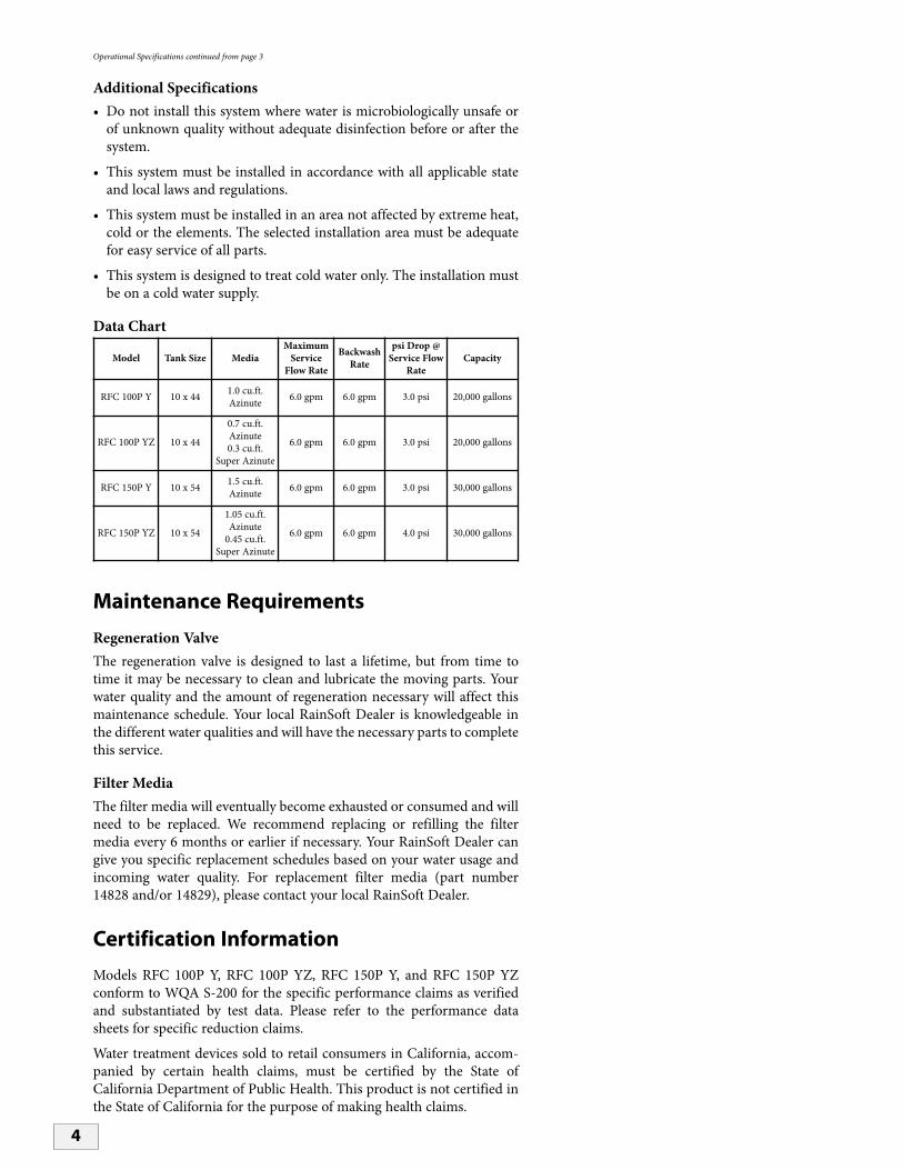
9. Set the Bypass Valve to Bypass• Move the bypass valve handles to the bypass position. The valve
handles should be perpendicular to the pipes (see figure 4).
10.Install the Drain Line and Air Gap (Air Gap Not Supplied)• Connect the 1/2 inch ID drain line to the drain outlet on back of
the valve, opposite the inlet connection (see figure 5). A fitting isrequired to connect the female pipe thread to the drain line.
• Run the drain line to the air gap (see figure 6).
11.Create the Electrical Connection• Remove the supplied wire from the warranty pack.
• Attach the U shaped connectors (supplied) to the wire with acrimping tool (not supplied).
• Connect the wire to the transformer (see figure 7).
• Insert the other end of the wire, with the connector, into the backof the control box (see figure 7).
• Plug the transformer into a 110 VAC 60 Hz or 230 VAC 50 Hzoutlet.
7
Helpful Tip: The drain line operates underpressure and can be installed higher thanthe filter.
! Important Notes: The air gap should be twotimes the diameter of the drain line or aminimum of two inches. Please check yourlocal plumbing codes to ensure compli-ance.
The air gap must be open and free ofobstructions to achieve a proper backwashrate (see figure 6).
1/2" ELBOW
1/2" SPRING CLIP
1/2" DRAIN LINE
Helpful Tip: If the wire is too short, use thesupplied connectors and shrink tubing tolengthen the wire (see figure 7).
Helpful Tip: Squeeze the connector torelease it from the box.
Helpful Tip: Check the transformer label forthe correct voltage requirement.
Figure 4
Figure 5
Figure 6
Figure 7

System Start Up
1. Turn on the Water and Check for Leaks• Close all faucets and turn the water back on at the water meter or
pressure tank.
• Check for leaks. If a leak is present, drain the plumbing againbefore soldering.
2. Flush the Remaining Debris from the System• Open the cold water faucet on your bathtub.
• Allow the system to flush the remaining dirt and debris into thebathtub, until the water runs clear.
• Open all remaining faucets and allow the plumbing to release anytrapped air in the system.
• Close all faucets.
3. Open the Bypass Valve• Move the bypass valve handles to the service position. The valve
handles should be parallel to the pipes (see figure 8).
• Open the bathtub faucet again and allow the system to fill and flushfor approximately 5 minutes.
4. Flush the Remaining Untreated Water from the Water Heater• Run hot water in the bathtub to remove any remaining untreated
water.
5. Set the Timer• Please refer to the System Settings on pages 9-10.
8
Helpful Tip: This procedure will preventdirt and debris from entering the valve.
Figure 8
! Important Note: Additional flushing maybe required to remove residue from theplumbing.
System Settings
Operation of the TimerThe timer is designed for years of maintenance free service, withminimal initial setup. Once the parameters are established and set bya RainSoft Representative, there is no need to adjust or change theparameters of the timer. If a noticeable change in the quality of yourwater has taken place, please contact your RainSoft Dealer immedi-ately.
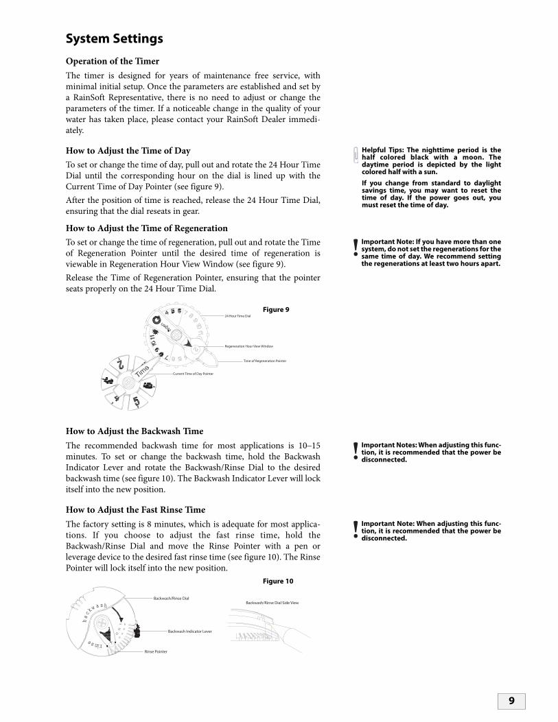
How to Adjust the Time of DayTo set or change the time of day, pull out and rotate the 24 Hour TimeDial until the corresponding hour on the dial is lined up with theCurrent Time of Day Pointer (see figure 9).After the position of time is reached, release the 24 Hour Time Dial,ensuring that the dial reseats in gear.
How to Adjust the Time of RegenerationTo set or change the time of regeneration, pull out and rotate the Timeof Regeneration Pointer until the desired time of regeneration isviewable in Regeneration Hour View Window (see figure 9).Release the Time of Regeneration Pointer, ensuring that the pointerseats properly on the 24 Hour Time Dial.
How to Adjust the Backwash TimeThe recommended backwash time for most applications is 10_15minutes. To set or change the backwash time, hold the BackwashIndicator Lever and rotate the Backwash/Rinse Dial to the desiredbackwash time (see figure 10). The Backwash Indicator Lever will lockitself into the new position.
How to Adjust the Fast Rinse TimeThe factory setting is 8 minutes, which is adequate for most applica-tions. If you choose to adjust the fast rinse time, hold theBackwash/Rinse Dial and move the Rinse Pointer with a pen orleverage device to the desired fast rinse time (see figure 10). The RinsePointer will lock itself into the new position.
9
Helpful Tips: The nighttime period is thehalf colored black with a moon. Thedaytime period is depicted by the lightcolored half with a sun.
If you change from standard to daylightsavings time, you may want to reset thetime of day. If the power goes out, youmust reset the time of day.
Regeneration Hour View Window
Time of Regeneration Pointer
24 Hour Time Dial
Current Time of Day Pointer
! Important Note: If you have more than onesystem, do not set the regenerations for thesame time of day. We recommend settingthe regenerations at least two hours apart.
! Important Notes: When adjusting this func-tion, it is recommended that the power bedisconnected.
2515
5
8
2330
3846
ns ireb
ca
k wa s h
Backwash/Rinse Dial
Backwash Indicator Lever
Rinse Pointer
! Important Note: When adjusting this func-tion, it is recommended that the power bedisconnected.
Backwash/Rinse Dial Side View
Figure 9
Figure 10
System Settings continued from page 9
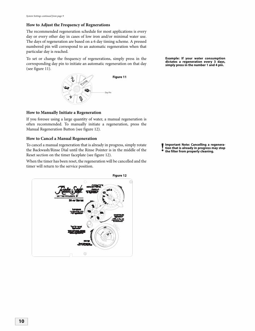
How to Adjust the Frequency of RegnerationsThe recommended regeneration schedule for most applications is everyday or every other day in cases of low iron and/or minimal water use.The days of regeneration are based on a 6 day timing scheme. A pressednumbered pin will correspond to an automatic regeneration when thatparticular day is reached.
To set or change the frequency of regenerations, simply press in thecorresponding day pin to initiate an automatic regeneration on that day(see figure 11).
How to Manually Initiate a RegenerationIf you foresee using a large quantity of water, a manual regeneration isoften recommended. To manually initiate a regeneration, press theManual Regeneration Button (see figure 12).
How to Cancel a Manual RegenerationTo cancel a manual regeneration that is already in progress, simply rotatethe Backwash/Rinse Dial until the Rinse Pointer is in the middle of theReset section on the timer faceplate (see figure 12).When the timer has been reset, the regeneration will be cancelled and thetimer will return to the service position.
10
Example: If your water consumptiondictates a regeneration every 3 days,simply press in the number 1 and 4 pin.
Day Pin
! Important Note: Cancelling a regenera-tion that is already in progress may stopthe filter from properly cleaning.
25155
8
23303846
ns
ire
bc akw
ash
Figure 11
Figure 12

11
If the troubleshooting guide did not resolve the symptom, please contact your local RainSoft Dealer for service. Ifyou cannot locate your local RainSoft Dealer, please contact RainSoft Customer Service at 1-800-860-7638 or logonto www.rainsoft.com for the name and location of your nearest Dealer.
Troubleshooting Guide
Symptom Cause Solution
1. System Fails to Regenerate Automatically
2. System Regenerates at the Wrong Time
1. The power supply is plugged into anintermittent or dead power source.
1. Connect to a constant power source.
1. The timer is not set properly. 1. Reset the time of day and hour of regeneration.
4. Loss of Water Pressure
1. Low pressure to the system. 1. Bypass the system to confirm the problem.If the problem still exists after bypass, it is not related to the RainSoft equipment. Have your water distribution system checked.If the problem is resolved after bypass, contact your RainSoft Dealer for service.
2. The proper day pins are not depressed. 2. Push in the proper day pins.
2. The time is off due to daylight savings. 2. Reset the time of day.
3. Poor Water Quality 1. The raw water has changed. 1. Call your RainSoft Dealer for a new water analysis.
2. The bypass valve is open. 2. Close the bypass valve.
3. The power supply is disconnected. 3. Plug in the power supply.
5. Constant Flow to the Drain
1. Foreign material in the valve. 1. Call your RainSoft Dealer to clean the valve.

12
Valve Exploded View and Parts List
21
17
16
21
20
19
14
18
12
1115
10 226
1
2
3
23
4
13
5
7
8
9
24
Item Quantity Part Number Description1 1 17863 Composite Valve Body2 1 17864 Spacer End3 4 17865 Internal Spacer4 5 17866 Internal Seal5 1 18160 Retainer & Down Flow Piston6 1 17557 Composite Bypass Valve7 1 17869 End Plug Assembly8 5 17870 10-24 x .812 Screw Hex Washer Head9 1 17871 Piston Rod
10 1 17887 Retainer Drain11 1 17888 O-ring - 12112 1 17889 O-ring - 33613 1 17939 1/2″ NPT X 1/2″ Barb Poly Elbow14 1 13329 O-ring - 01415 1 17949 Injector Seal16 1 17950 Injector Cap17 2 17951 10-24 x 1.0 Screw Hex Washer Head18 1 18271 Brine Valve Plug19 1 17958 O-ring - 01520 1 18270 Filter Plug21 2 17617 C-Injector Plug Assembly22 1 17560 3/4″ Coupling Adapter Assembly23 1 18287 6.0 Drain Line Flow Control Assembly24 1 18445 Distributor Tube Retainer O-ring
13
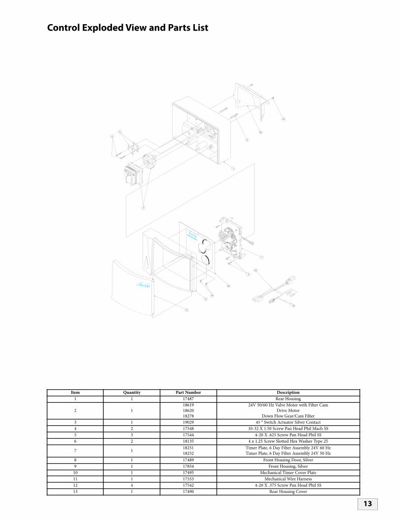
Control Exploded View and Parts List
1
4
6
2
3
12
8
9
10
5
7
R 2
3
67
13
12
11
Item Quantity Part Number Description1 1 17487 Rear Housing
2 1186191862018278
24V 50/60 Hz Valve Motor with Filter CamDrive Motor
Down Flow Gear/Cam Filter3 1 19029 45 ° Switch Actuator Silver Contact4 2 17548 10-32 X 1.50 Screw Pan Head Phil Mach SS5 3 17544 4-20 X .625 Screw Pan Head Phil SS6 2 18135 4 x 1.25 Screw Slotted Hex Washer Type 25
7 1 1825118252
Timer Plate, 6 Day Filter Assembly 24V 60 HzTimer Plate, 6 Day Filter Assembly 24V 50 Hz
8 1 17489 Front Housing Door, Silver9 1 17854 Front Housing, Silver
10 1 17495 Mechanical Timer Cover Plate11 1 17553 Mechanical Wire Harness12 4 17542 4-20 X .375 Screw Pan Head Phil SS13 1 17490 Rear Housing Cover

14
LimitedLifetime Warranty
For as long as you own the equipment
RainSoft Division of Aquion Water Treatment Products, believing its
RFC WATER FILTRATION SYSTEMto be of exceptional quality, hereby warrants said equipment to its first purchaser at retail as follows:
THE TREATMENT TANK AND VALVE ARE WARRANTED AGAINST DEFECTS IN MANUFACTURE FORTHE LIFETIME OF THE FIRST PURCHASER AT RETAIL.
THE ELECTRICAL PARTS (IF APPLICABLE) ARE WARRANTED AGAINST DEFECTS IN MANUFACTUREFOR FIVE YEARS AND PRO-RATA WARRANTED FOR AN ADDITIONAL FIVE YEARS.
THE FILTER MEDIA IS NOT WARRANTED. THE FILTER MEDIA SERVICE LIFE IS DEPENDENT ONSPECIFIC WATER CONDITIONS AND USAGE.
This warranty begins at the time the equipment is first connected for use, and is contingent upon the return of a signedowner's registration card.
This warranty does not require replacement of the entire unit. If the equipment does not perform properly, you shouldrequest service from the dealer that sold you the equipment. If you are not satisfied, you should notify our CustomerService Manager. If we are not able to arrange local servicing, you should send the defective part(s) (or, if you prefer,send the entire unit,) directly to the manufacturer, freight prepaid, with proof of purchase and a copy of this warranty.The defective part(s) (or entire unit) will either be repaired or new RainSoft part(s) furnished, for a nominal charge tocover labor, handling, packing and the increase, if any, in the retail price of the part(s) since the date of purchase.Genuine RainSoft parts must be used. Failure to use genuine RainSoft parts will void the warranty and certifications.
This warranty does not include labor charges, and does not cover installation, transportation, or any other claims ortorts. Some states do not allow the exclusion or limitation of incidental or consequential damages, so parts of the abovelimitation or exclusion may not apply to you.
This warranty gives you specific legal rights, and you may also have other rights which vary from state to state. You alsohave implied warranty rights. In the event of a problem with warranty service or performance, you may be able to go toa small claims court, a State court, or a Federal District Court.
This warranty is void if equipment is not installed and operated according to instructions. It does not apply to damagecaused by abuse, accident, neglect, freezing, fire, or other abnormal conditions beyond the company’s control. Thiswarranty is void on any part from which the manufacturing date has been removed or made illegible.
Benefits will be provided by various types of RainSoft equipment when installed and operated according to the manu-facturer's recommendations. Operational, maintenance and replacement requirements are essential for the product toperform as advertised. All claims are based on the best available information at the time of printing. Manufacturermakes no representations as to the suitability of this equipment for a particular application. Buyer relies entirely on thedealer's recommendations in the purchase of this equipment.
Independent RainSoft dealers may include, together with your RainSoft product, a product or component that is notmanufactured by RainSoft or their parent company, AWTP, LLC. Any non-RainSoft product may be covered by themanufacturer of that product, and is not covered by the RainSoft warranty. AWTP, LLC does not warrant that yourRainSoft product and the non-RainSoft product will perform properly when used together, and assume no liabilitytherefore.
RainSoft Division of Aquion Water Treatment Products2080 East Lunt Avenue
Elk Grove Village, Illinois 60007 USA

15
Installer Specification Sheet
Dealer Name:
Phone Number:
Installation Number:
Installation Date:
Model Number:
Serial Number:
Line Pressure: (psi)
Iron:
pH:
Sulfur:
Backwash Flow Rate: (gpm)
Recommended Regeneration Frequency: Every Day
Recommended Backwash Time: (10 minutes minimum)

RainSoft Division of Aquion Water Treatment Products2080 East Lunt Avenue
Elk Grove Village, Illinois 60007Main Switchboard: 1.847.437.9400Customer Service: 1.800.860.7638
www.rainsoft.com©2007 RainSoft Division of AWTP, LLC