RF impedance probe measurements of ionospheric electron ... · propagation experiment was performed...
8
JOURNAL OF RESE ARCH of the National Burea u of Sta ndards-D. Radio Propagation Vol. 66D, No. 6, November- De cember 1962 RF Impedance Probe Measurements of Ionospheric Electron Densities 1. A. Kane , 1. E. Jackson, and H. A. Whale Contribution From Godda rd Space Flight Center, Gr eenbelt, Md. (Received March 29, 1962; revised M ay 31, 1962) The Aerob ee -Hi ro cket, NASA 4.07, obt a in ed verti cal el ect ron density profiles in the ionosphere s imultan eously by the Seddon OW prop agati on tec hniqu e a nd by an RF im- pedance prob e tec hniqu e. The experimen tal goal was to assess th e perfo rmance of the RF prob e aga in st t he acc urate values from the O'v V m ethod. In the RF probe method, the elect ron densi ty N was de ri ved from the dielectric cons tant J{ of the me dium at a fre quency / = 7.75 Mc/s. If the earth 's magn et ic fi eld is neglecte d, the relation between these quanti- t ies m ay be g iv en as K = 1- (S IN/ f2). An expression for the dielectri c cons ta nt including the e ff ects of the earth's m agn etic fi eld is derived. Th e fr act ional err or introduced by neglecting the earth's fi eld is of t he order of (fH// )' where / H is the electron gyro fre quency. It was concluded that , with allowance for the po sitive ion sheat h aro und the rocket, the RF imp edan ce probe can yield reli able values of el ect ron densi ty . Th ese valu es were ob ta in ed fro m chan ges in t he cap acitiv e part of the probe's imp edance. Sma ll , ap parently anomalous chang es in t he res istive part were also oLserved. 1. Introduction Th e most accur ate elec tron density profil es of the ionospher e have b een obtained by Seddon 's CW I propaga tion me thod [Se ddon, 1953], which yields I excellent r esults for rocket soundin gs in a fairly quiet , horizon tally uniform ionospher e, particularly if corr ections are made for obliqui ty eff ects [Jackson, i 1957]. However, in order that synopti c meas ur e- ments m ay be mad e under a ll ionospheric conditions, other techniqu es are required. Th e RF probe te chniqu e discussed in the pr esent paper was de- veloped to provide such a m et hod . 1t is based on th e r es ul ts of several pr evious rocket fli gh ts [Jackson and Pi ckar , 1957] in which the ionosphere was observ ed to hav e an eff ec t on the impedance of . rocket-borne antennas. Th e ant enn a impedan ce . was d. et ermined durin g th ese earlier rocket fli ghts by monitoring the volt ages on both sid es of th e matching network between the ant enna and th e I CW transmitter. With the aid of pr e-flight cali- brations, th ese t wo sets of obser vations were suf- fi cent to d etermin e bo th the r eactive and th e r esistive component s of the an te nn a impedan ce, bu t it was no t possible to rel ate the observed impedance i vari at ions to ambi ent ionospheric parameters unti l the proper pr ecautions were taken to minimize co n tamin ation of the rocket environment. Wh en this was effe cted (mainly by sealing the rocket fuel tanks after th e completion of propulsion), it was found that elec tron densities derived from th e impedan ce observation s showed very good correlation with the CW propagation results [Jackson and Kan e, 1959]. Since the ant ennas used for the RF impedan ce probe measurenent s were elec tri cally short , th eir impedances were primarily capacitive. This capac- it ance changed by an amount proportional to the ambient elec tron density. In these experim en ts el ec tron densiti es were obt ained by a ttribu ting th e c apa citan ce changes to changes in the dielec tri c const ant K of th e medium a nd th en calculating th e electron density from the relation: K = 1_ 81N P (1) where N is the densi ty in el ec Ll' ons/cm 3 a nd j is the op er a ting frequency in kc/ s. In p ast experiments th e electron densi ty valu es derived from eq (1) had been too small by a factor of about 3. For some applications thi s could be considered fort un ate, sin ce it indi cate d th at the impedance of a tr an smit ting a nt enna was a ff ec ted less by the ionosphere than mi ght have b ee n ex- p ect ed from the ambient ioniz at ion. It was tent a- tiv ely concluded from these early r esults th at the ionospheric e ffe cts were re du ced, primar ily by dis tortion of th e ant enna environment du e to the large RF amplitud e ( in the order of 200 v) required for the CW prop agat ion experimen t. Th e rocket experim ent described in this paper was performed to see if th e accur acy of th e RF prob e would be sub stanti ally improved by making the meas ur e- ments at low RF voltages. A pr eliminary acc oun t of the r es ults of thi& experiment has b een gi ve n by J ackson and K ane [1960]. In order to compare th e elect ron densi ty valu es obt ained from the RF prob e with the ac tual densiti es , a CW prop agat ion experiment was performed durin g thi s rocket fli ght a t 7.75 and 46 .5 M c/s on a time- sharing basis. To fulfill th e requirement s of both 648645- 62--1 641
Transcript of RF impedance probe measurements of ionospheric electron ... · propagation experiment was performed...

JOURNAL OF RESEARCH of the National Burea u of Sta ndards-D. Radio Propagation Vol. 66D, No. 6, November-December 1962
RF Impedance Probe Measurements of Ionospheric Electron Densities
1. A. Kane, 1. E. Jackson, and H. A. Whale
Contribution From Goddard Space Flight Center, Greenbelt, Md.
(Received March 29, 1962; revised May 31, 1962)
The Aerobee-Hi rocket , N ASA 4.07, obta ined vertical electron density profiles in the ionosphere simultaneously by the Seddon OW propagation technique and b y an RF imp edance probe technique. The experimental goal was to assess the performa nce of t he RF probe against t he accurate values from the O'vV method . In the RF probe method, t he electron density N was deri ved from the dielectric constant J{ of t he medium at a frequency / = 7.75 Mc/s. If t he ea rth 's magnetic fi eld is neglected, t he relation between these qua nt it ies may be given a s K = 1- (SI N/f2) . An expression for t he dielectric constant including t he effects of t he eart h's magnetic fi eld is derived . The fractional error in t roduced by neglecting the ear th 's fi eld is of t he order of (fH// )' where / H is t he electron gyrofrequency.
It was concluded t hat, with allowance for t he posi tive ion sheath around t he rocket, t he R F impeda nce probe can yield reliable values of electron density. These values were ob tained from cha nges in t he capacitive par t of t he probe's impedance. Small , apparent ly a nomalous changes in t he resist ive par t were also oLserved.
1. Introduction
The most accurate elec tron density profiles of the ionosphere have been obtained by Seddon's CW
I propagation method [Seddon, 1953], which yields I excellent results for rocket soundings in a fairly
quiet, horizontally uniform ionosphere, par ticularly if corrections ar e made for obliquity effects [Jackson ,
i 1957]. However , in order that synoptic measurements may be made und er all ionosp her ic conditions, other t echniques are required. The RF probe technique discussed in the present paper was developed to provide such a method . 1t is based on the resul ts of several previous rocket fligh ts [Jackson and Pickar, 1957] in which the ionosphere was observed to have an effec t on the impedance of
. rocket-borne antennas. The antenna impedance
. was d. etermined during these earlier rocket fligh ts by monitoring the voltages on both sides of the matching network between the antenna and the
I CW transmitter. With the aid of pre-flight calibrations, these two sets of observations were sufficent to determine both the reactive and the resistive components of the antenna impedance, but it was no t possible to r elate the observed impedance
i variations to ambient ionospheric parameters until the proper precau tions wer e taken to minimize contamination of the rocket environment . When this was effected (mainly by sealing the rocket fuel t anks after the completion of propulsion), it was found that electron densities derived from the impedance observations showed very good correlation with the CW propagation r esults [Jackson and K ane, 1959].
Since the antennas used for the RF impedance probe measurenents were electrically short, their
impedances were primarily capaci tive. This capacitance changed by an amount proportional to the ambient elec tron density. In these experim ents elec tron densities were obtained by a ttributing the capacitance changes to changes in the dielec tric constant K of the medium and then calcula ting the electron density from the relation:
K = 1_ 81N P
(1)
where N is the density in elec Ll'ons/cm3 and j is the oper ating frequency in kc/s.
In past experiments the electron densi ty values derived from eq (1) had been too small by a factor of about 3. For some applications this could be consider ed for tunate, since i t indicated that the impedance of a transmit ting antenna was affec ted less by the ionosphere than might h ave been expected from the ambient ionization. It was tentatively concluded from these early results that the ionospheric effects were reduced, primar ily by distortion of the antenn a environmen t due to t he large RF amplitude (in the order of 200 v) r equired for the CW propagation experimen t. The rocket experim ent described in this paper was performed to see if the accuracy of the RF probe would be substantially improved by making the measurements a t low RF voltages. A preliminary account of the results of thi& experiment has been given by J ackson and K ane [1960].
In order to compare the electron density values obtained from the RF probe with the actual densities, a CW propagation experiment was performed during this rocket flight a t 7.75 and 46 .5 M c/s on a timesharing basis. To fulfill the requirements of both
648645- 62--1 641

experiments, the amplitude of the £L,ed-frequency 7.75-Mc/s signal applied to the antenna was cycled periodically through the following levels: 0.2, 2, 2, and 200 v, each with a duration of 1 sec. When the nominal free-space RF amplitude of 200 v was on the antenna, the GVV propagation experiment was performed to establish the reference electron density profile; the 0.2-v and 2-v levels were used for the RF probe experiments. Thus, the OW propagation experiment was performed during 1 sec out of every four , giving approximately one value of electron density every 4 km in the region of interest. The OW propagation experiment was thus slightly handicapped, since there were not quite enough data points to plot the curvature of the resulting profile precisely. This caused the profile to appear somewhat jagged; nevertheless, it was accurate enough to assess the quality of the RF probe data.
The vertical-incidence ionospheric sounding station located near the launching site provided additional support for the RF probe experiment. A quiet ionosphere was desired in order to optimize the measurements made by the OW propagation experiment; therefore, continuous monitoring of the ionosphere was conducted prior to the firing to insure that this requirement would be met. Also, with the experiment performed under quiet conditions, the pI -I records ob tained could readily be analyzed and a third independent determination of the electron density profile thereby obtained.
Finally, comparison experiments such as Langmuir probe, ion trap, and electric field meter measurements were included in the rocket, making it possible to acquire furth er data for correlation purposes.
2 . Electron Densities From the CW Propagation Experiment
In the OW propagation experiment two phasecoherent signals, at 7.75 Mc/s and 46 .5 Mcjs, were transmitted from the rocket and received on the ground with circularly polarized antennas. The instrumentation at the receiving station [Jackson and Spaid, 1959] provided data for both the ordinary and the extraordinary components of the 7.75 Mc/s signals. Sinca the electron density could be derived from either the ordinary or the extraordinary ray data, this experiment provided two independent measurements of the electron density profile. The two curves are shown in figure 1, where electron density is plotted against the time after launching. (The peak of the flight occurred about 250 sec after launch time. ) Results obtained from this type of measurement are most accurate when the radial velocity of the rocket from the receiving site is large and the transverse velocity small. Near the peak the radial velocity is small, and any changes in the ionization between the rocket and the receiving station may appear as large apparent changes in the electron density at the rocket. This effect can be observed in the large fluctuations in the results between 200 and 300 sec (fig. 1).
4 X 10⁵
'"
;v;~ "E f} u
;;; 3 X 10 5 )( ;'
-
\ \ z 0 0: f-U f i w
\J --' w ; >: 2 X I0 5 \ "
f-- If: : '
</) , . z
~I w
\' \ 0
z 0 0:
105 f- -
j - ORDINARY u
w -.- EXTRAORDINARY --' w
1\ 0 1 0 100 200 300 400 50"
TI ME , sec
FIGU RE 1. ElectTon den sity ve1'SUS fli ght time deTived fT om pTopagation data on ordinaTY and extraordinary polarization modes .
E
"" w
1128 CST , Sept, 14, 1959, F t . Churchill , M anitoba, Canada.
220 r----r---.----,----,----~---,----r_--,
180
..... ,ASCENT - ,- DESCENT
g 140 f
f-' ..
100
60 ~ __ -L __ ~ ____ ~ __ ~ ____ L-__ _L ____ L_ __ ~
o ELECTRON DENSITY, EL ECTRONS / cm3
FIGU RE 2. Altil1tde dependence of the mean electTon density derived f1'om the propagation experiment dUTing Tocket ascent and descent.
1128 CST , Sept, 14, 1959, F t . Churchill , M anitoba, Canada.
If the data for the 200- 300 sec period are disregarded, ther e is good agreement between the , electron densities obtained from the two polarization components. The slight differences that are noticeable are due in part to the fact that the ordinary and the extraordinary rays followed slightly differen t paths in the ionosphere and were affected differently by irregularities and changes in the region between , the rocket and the receiver. Thus a mean value of the two curves should be a sligh tly better measure
642

of the electron density at the roeket than that obtained from either ray by itself. Such a mean lourve is plotted in figure 2, where the electron density I s shown as a function of al titude for the ascending t \~olid line) and descending (dashed line) parts of the rocket trajectory. From this comparison it can be seen that the measured electron densities differed by an appreciable factor for the ascending and the descending parts of the flight. The difference is ,most noticeable in the vicinity of 120 km where
Idescent values were about 50 percent greater than the ascent values. This indicates the presence of
Ihorizontal gradients, whose presence rE'duces tl1e accuracy of the obliquity correction required to [derive the descent values. I
3. The RF Probe
As was indicated earlier, the sensor used in the 'RF probe experiment is a capacitor whose dielectric !constant is that of the ambient medium. Configurations which could be used for this capacitor include parallel plates, collinear cylindrical whips, and insulated sections of a rocket surface. In the
I experiment under discussion the sensor was a rocketborne 7.75 Mc/s antenna consisting of two 3-m collinear whips. Because of its short electrical length, the impedance of thi.s antenna at 7.75 Mc/s was primarily capacitive.
Since the method formerly used for impedance measurements (monitoring the input and output lof the matching network) was found to have poor resolution and to suffer from drifts in the calibration curve, an improved method was developed for the NASA 4.07 . This method can be understood from
I figure 3, which shows the circuit and responses of I the RF probe. The circuit consisted of a lowimpedance 7.75 Mc/s signal source and a matching
I
network connecting this source to the probe. Thc impedance probe, together with its associated net-[work, exhibited a parallel resonance for the propel' value of the variable capacitor C- C. The circuit :was designed so that resonance would occur neitr the low capacitance end of the capacitor when the probe was in a nonionized medium. In the iono-
I
sphere, the capacitance of the probe decreased because of the presence of free electrons, and additional capacitance had to be provided by the capaci[tor C-C to achieve parallel resonance.
I The amplitude of the RF signal appearing at the
probe was detected at the point A (fig. 3) and telemetered to the ground . In operation, the capacitor C- C WflS rotated continuo usly, causing the RF response of the probe circuit to vary in the
,manner indicated by Lhe responses shown in the figure. The probe capacitance determined the position of the response peaks whose amplitude indicated the resistive loading. The dielectric constant of the medium was calculated from this capac-
litance and then used to calculate electron densities with the aid of eq (1). The error inherent in eq (1),
las a result of neglecting the effect of the earth's magnetic field, was at most 4 percent (sec appendL\::).
~ LJ - CAPACI TOR ROTATION REFERENCE I I
~ Cma?i' - CAPAC ITANCE OF TUNING CAPACITOR jCm~ i I I I I I I
: J\JJ\ ~ 75 ~ - RESPONSE IN FREE SPACE
I (78km) I
I I I
~I: u I I I ~ 9 8 j{ii2kiTli -RESPONSE NEAR E MAX
wi : I :;;; I I :
i= 1~, I 250 - RESPONSE AT PEAK OF
j2i9iTiJ TRAJECTORY I I I I I I
~I I I I
3951----_...".-,;-;!;-;::=-_~
~ I I I I I I
~ '12 L (85 m) J 0.8 SECOND
ROCKET ANTENNA
,r '---+---'0 7.75 Me/s
SI GNA L _ SOURCE .
FIGURE 3. R esponse cw·ves oj the RF probe circuit .
1128 CST, Sept. 14, 1959, F t . Churchill , M ani toba, CfIl1 ada.
As mentioned earlier, a four-step time-sharing sequence wn,s used. The antenna probe was connected to the variable condenser C- C during the first two steps, when the nominal RF vol tage levels were respectively 0.2 and 2 v. For the third and fourth steps, the variable condenser was disconnected from the antenna probe nnd replaced by a fixed condenser selected to give resonance under freespace conditions. During the third step a nominal voltage of 2 v was used and Lhe ampli tude was again monitored at point A. This provided a means for detecting small ineguhrities which could have occurred during the l-sec period s n,llo tted for each step of the sequence. During sLeps 1, 2, and 3, the center tap of the matching transformer (fi g. 3) ,vas connected to ground. During the fourth step a nominal vol tage of 200 v was applied to the probe, which was then used as the low-frequency transmitting antenna for the CW propagation experiment. In this case the fixed capacitor was used instead of the variable capacitor C-C in order to prevent large variations in amplitude and phase at the lowfrequency antenna. Either of these variations would have introduced severe complications into the CW propagation experiment. To permit detection of a possible collection of electrons by the transmitting antenna, the center tap of the matching network was disconnected from the ground during the fourth step of the sequence and connected to a current-measuring circuit. The antenna voltage was also monitored during this fourth step to indicate effects of the ionosphere upon the antenna impedance while the CW propagation experiment was in progress.
643

"'E u ~ 3xlO z o cr >-u W ..J W
.; 2xl05 t: (f)
z w o
fA.!. ! "\} j 1
~ , \ ,I: ~ /! l.j. ::
\ 1: : J'" : _11:_ N PROPAGATION , .
TIME ,sec
FIG URE 4. Comparison of electron density versus flight time
220 r----,---,----,----,--~r_--_.----._--~
E xc
w o
180
::J 140 >->-..J <I:
><,:/ 100 .x
............. x ...... -,x'
ASCENT -x- DESCENT
for both the RF probe and CW propagation methods. 60 '--_-'-_--''--_-L-_--'-____ ..l....-_--'-__ .l..-_...J
1128 CST, Sept. 14, 1959, Ft . Churchill , M anitoba, Canada.
Briefly, the experimental results of the RF probe observations were as follows:
(1) During the propagation experiment (with 200 v on the antenna) the effect of the ionosphere upon the antenna capacitance was only 30 percent of that calculated on the basis of ambient electron density. This result is in agreement with the previous observations made under similar conditions. During this last sequence a large electron current was collected by the antenna in the altitude range from 60 to 110 km, which is the region where electrical breakdown occurs [Jackson and Kane, 19S9]. However, above the breakdown region the current collected by the antenna was below the 10- 8 amp detection sensitivity of the current-monitoring circuit.
(2) No irregularities were indicated by the obser:rations made during the third step of the programmg sequence.
(3) The electron densities calculated from the response curves obtained during the first and second steps lie in the range 70 to 80 percent of the actual values. Therefore it is apparent that a substantial improvement in the accuracy of the RF probe was achieved by performing the measurements at low RF levels. The remaining difference between the RF probe and CW propagation techniques will be discussed in the section on the ion sheath. The electron densities derived from the responses obtained at the 0.2-v level are plotted against flight time as the solid curve in figure 4. Impedance measurements at 2.0 v yielded a profile only a few percent lower than the 0.2-v profile. The values obtained from the propagation method (mean of the ordinary and extraordinary ray results) are also plotted in figure 4. It should be noted that, in contrast to the CW propagation data, the RF probe data experienced no degradation during the time interval from 200 to 300 sec. The electron density derived from the RF probe measurements is plotted as a function of altitude in figure S. It is of interest
644
o 5 5 10 2 XIO 3XI0
ELECTRON DENSITY, ELECTRONS Icm 3
FIGURE 5. Comparison of electron density obtained by RF probe during rocket ascent and descent.
1128 cS'r, Sept. 14, 1959, Ft. Churchill, Manitoba, Canada.
to note that the absence of a deep "valley" in the daytime above the maximum of the E region was, in this instance, verified by a direct measurement.
(4) A comparison between the profiles derived I
from the RF probe, the CW propagation method experiment, and the P'1 record is given in figure 6. The P'1 record obtained during the flight is shown in figure 7. This ionogram was analyzed by means of a five-point reduction process based upon coefficients obtained by extrapolating Schmerling's [19S8] values to those appropriate in the la titude of Fort Churchill. As had been expected, the electron density values calculated from the P'1 record were in good agreement with the values obtained by the CW propagation method during the upward part of the flight.
4. Ion Sheath I
The difference between the two methods on the I
question of the absolute valu es of the electron density will now be considered (fig. 4). This difference is to be expected since, in the ionosphere, the rocket body and antennas will normally be enclosed in an ion sheath. If the photoelectric effect can be ignored, the rocket body and antennas will acquire a neL I negative charge due to the difference between the electron and positive ion velocities. The effect of i
this surface charge is to create in the adjacent . medium an electric field that depletes the electron content over a distance which can be represented as an equivalent sheath thickness. The rocket potential ~ is determined by the condition that the positive ion flux to the rocket surface is equal to the flux of electrons with energies greater than e~ (where e is the charge on an electron) . This process has been discussed by Jastrow and Pearse [19S7].
w o => l-
S 4
200
100
! f , x , I
I ~
PROPAGATION DATA ! R.F. PROBE DATA " x
X X X p'- f DATA I
..- .... /
I I
( I
I I I
I \ \ X
I xl I
/
104 10 5 106
ELECTRON DENSITY, EL ECTRONS/c m 3
FIGURE 6. Comparison of electron denstty derived from the RP .probe techniques, the ClV propagatwn expenment, and the wnosonde.
1128 CST , Sept. 14, 1959, Ft. Uhu rehill, Manitoba, Canad a.
The presence of the ion sheath means that the probe is not immersed in a uniform medium as had been postulated, but rather in a medium with a dielectric constant of unity over the dimension of the sheath thiclmess. This dielectric in turn is immersed in the dielectric medium of the ionosphere.
The electron density N' calculated from the measured probe capacitance will then b e related to the true ionospheric electron density N by the equation
N N' K' Oo'
1- --Os
(2)
where K' Oo is the measured probe capacitance and Os is the sheath capacitance. Because of the complicated geometry at the antenna base it is difficult to define precisely the sheath thickness and, consequently, the sheath capacitance. For the case of a long cylinder of radius H, the sheath thickness, a, can be estimated from the formula of Jastrow and Pearse [1957]:
le~ [ (R+a)2 J-t R + a = 1.5 X 10³-y N In -----rr -1 cm.
(3)
The capacitance per unit length of the cylindrical
FREOUENCY , Mc/s 2 3 4 5 6 7 10 15 18 I I I I I I I I I I I I I I I I
1000,
1 ! ~ , I-
~ 800
I • 1 ~ '( ~
1/ It ~ ,
.§ • ,: I 600
'" w
~ V- " I
!.
.~ i. ~ " !
I
.J 400 '" :::>
f-a: >
200 l-
I- .- lP -0"-
FIG(' RE 7. Ionogmm obtained during the l'ocket flight.
]]28 CST, Sept. 14,1959, Ft. Churchill, :\Ianitoba, Canada.
sh eath is given by
(4)
whoro t o is Lh e permittivity of free space. Equations (2) and (4) can be combined to give
N' JI.,T= . 1- 0.22K'ln (Hta) (5)
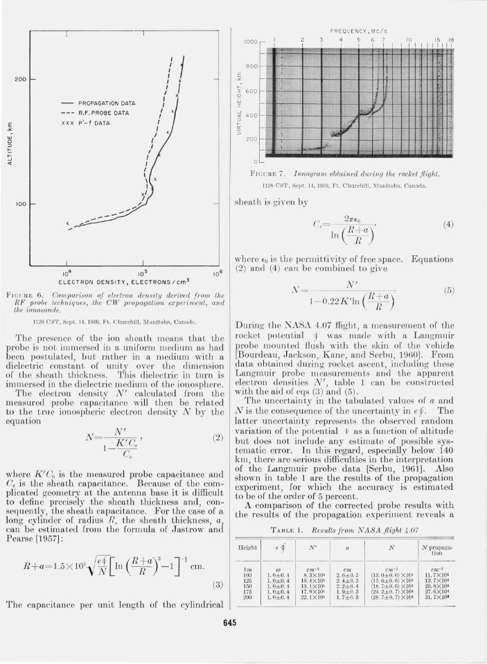
During th e NASA 4.07 flight , a measurement of the rocket potential p was made with a Langmuir probe mounLed flush with the skin or the vehicle [Bourdeau, Jackson , Kane, and Serbu, 1960]. From data obtained during rocket ascen t, illcluding these Langmuir probe measurements and the apparent electron densiLios N', Lable 1 can b e constructed with the aid or eqs (3) and (5).
The uncertainty in the tabulated values of a and N is the consequ ence of the uncertain ty in eg> . The latter uncertainty represents the observed random variation of the potential 1> as a function of altitude but does not include any estimate of possible systematic error. In this regard, especially below 140 km, there are serious difficulties in the interpretation of the Langmuir probe data [Serbu 1961], Also shown in table 1 are the results of the propagation experiment, for which the accuracy is estimated to be of the order of 5 percent.
A comparison of the corrected probe results with the results of the propagation experiment reveals a
TABLE 1. R esults frorn NASA flight 4.07
Height e ~ N' a N Npropaga-tion
---km eo cm- 3 em cm-3 cm- 3
100 1.0± 0.4 8. 3X I0 1 2.6±0.5 (13. O± O. 6) X I0' 11.7X I01 125 1. O± O. 4 10.4X lO' 2.4±0.5 (J 5. 6±0. 6) XI04 12.7X I04 150 1. O± O. 4 13.1XlO' 2. 2± 0. 4 (18. i ± O. 6) XI04 20.SXI01 175 1. O± O. 4 17. 9XlO' 1. 9±O. 3 (24. 2±O. 7) X IOI 27. 6X lOl 200 1. O±0. 4 22. 1X IO' 1. 7±Q. 3 (28. 7± 0. 7) X IOI 31. 7Xl(14 .
645
J
disagreement. This discrepancy is not unreasonable in view of the nature of the approximations used to compute the probe correction factor. In particular, complicated geometry near the antenna base allows a small amount of strfLY capacitance to be entirely within the sheath. The effect of this parallel stray capacitance is essentially to magnify the pro be correction factor by 1 + WB/CO), where CB/CO is the ratio of this stray capacitance to the total free-space antenna capacitance. Although the precise value of CB/Ce is unknown, it is probably less than 0.2; and, since it should bc proportional to the sheath dimension, it should decrease with increasing altitude. It will be noted, however, that the difference between the propagation results and the corrected pro be results (table 1) shows a somewhat different altitude variance than does the sheath dimension. TIllS could be due to electron depletion by attachment to molecules coming from a small leak in some pressurized compartment of the rocket (most likely a small leak in the valve used to seal the rocket fuel tanks) . The supposed leakage procecds by effusion above 100 Im1 and would therefore be essentially constant over the short time interval of the rocket flight. Such a mechanism could also affect the Langmuir probe results.
It is hoped that some of these questions will be resolved in the ncxt rocket flight in which it is planned to repeat this experiment with the following refinements: (1) a guard ring arrangement will be provided to eliminate the uncertain tics associated with the antenna base geometry; (2) the Langmuir probe measurements will be performed with higher resolution; (3) a d-c voltage will be programed on the antenna to vary the sheath dimension; (4) the RF impedance measurement will be performed at two exploring frequencies to determine the effectivc sheath capacitance; and (5) the RF probe sampling rate will be increased by a factor of at least 10.
C,')
z o <t
0 . 20
g 0.15
w > I-
'" '" w
'" ~ 0.10 -w C,')
Z <t I U
w > ~ 0.05 ..J W a:
AS CENT DES CENT
/ /
/
I /
I I
I I
I I
I I
I
I I
I
/ I
o L~------==----~~/_/L-______ ~ ______ -L __ ~ o 6 0 100 14 0 180 220
ALT ITUDE . km
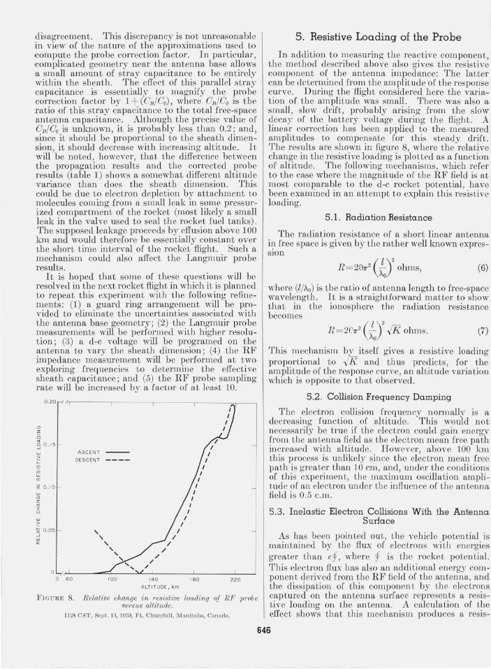
FIGURE 8. Relative change in Tesistive loading of RF 1J1'ob e vel'SUS altitude.
11 28 OST , Sept. 14, 1959, Ft. Ohurchill , M anitoba, Oanada.
5. Resistive Loading of the Probe
In addition to measuring the reactive component, the method described above also gives the resistive component of the antenna impedance: The latter can be determined from the amplitude of the response curve. During the flight considered here the variation of the amplitude was small. There was also a small , slow drift, probably arising from the slow decay of the battery voltage during the flight. A linear correction has been applied to the measured amplitudes to compensate for this steady drift. The results are shown in figure 8, where the relative change in the resistive loading is plotted as a function of altitude. The following mechanisms, which refer to the case where the magnitude of the RF field is at most comparable to the d-c rocket potential, have been examined in an attempt to explain this resistive loading.
5 .1. Radiation Resista n ce
The radiation resistance of a short linear antenna iJ?- free space is given by the rather wellimown expresSlOn
R = 207r2 (faY ohms, (6)
where (l/Xo) is the ratio of antenna length to free-space wavelength. It is a straightforward matter to show that in the ionosphere the radiation resistance becomes
R = 2C7r2 (;J2 "11K ohms.
This mcchanism by itself gives a resistive loading proportional to "IrK. and thus predicts, for the amplitude of the response curve, an altitude variation which is opposite to that observed.
5.2 . Collision Frequency Damping
The electron collision frequency normally is a decreasing function of altitude. This would not nccessarily be true if the electron could gain energy from the antenna field as the electron mean free path increased with altitude. However, above 100 km this process is unlikely since the electron mean free path is grcater than 10 em, and, under the conditions of this experiment, the maximum oscillation amplitude of an electron under the influcnce of the antcnna field is 0.5 c.m.
5 .3. Inelastic Electron Collisions With the Antenna Surfa ce
As has been pointed out, the vchicle potential is maintained by the flux of electrons with energies greater than ep , where p is the rocket potential. This electron flux has also an additional energy component derived from the RF field of the antenna, and the dissipation of this component by the electrons captured on the antenna surface represents a resistive loading on the antenna. A calculation of the effect shows that this mechanism produces a reS1S-
646
I tive loading of the proper altitude dependence but approximately one order of magnitude smaller than
1 that observed.
5 .4. Excitation of Electro-Acoustical Waves
Another resistive loading factor might arise from I the production of an electron pressure wave due to interaction of the RF field and the antenna ion
I sheath. Such a wave might absorb energy and thus contribute to the resistive loading. This mechanism is considered more fully in a separate paper [Whale, 1962].
1 6 . Effect of Irregularities in the Ionosphere
In the case of an oblique rocket trajectory, the ! accuracy of electron density profiles obtained with I the propagation experiment is limited by the assumpI tion that the ionosphere is horizontally uniform.
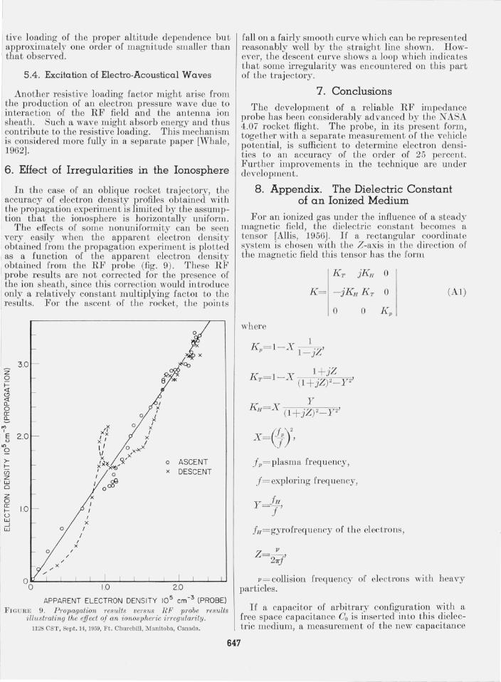
The effects of some nonuniformity can be seen very easily when the apparent electron density obtained from the propagation experiment is plotted
I as a: function of the apparent electron density obtamed from the RF probe (fig. 9). These RF
I probe results are not corrected for the presence of
I the ion sheath , since this correction would introduce only a relatively constant multiplying factOl to the results. For the ascent of the rocket, the points
z o I«
II Cl..
'" I
3.0
' E 2.0 IU1U
o
I ~ (f)
I ~ o z o g: 1.0 u W -.J W o
/
I X
I
x I I
8 '"
o ASCEN T x DESCENT
APPARENT ELECTRON DENSITY 10 5 em -3 (PROBE)
I FIGURE 9. P ropagation rewlls versus RF probe results i llustrating the effect of an ionospheric iI-regularity.
1128 CST, Sept. 14, 1959, Ft. Churchill , M anitoha , Canada.
fall on a fairly smooth curve which can be represented reasonably well by the straight line shown. However, the descent curve shows a loop which indicates that some irregularity was encoun tered on this part of the trajectory.
7. Conclusions
The development of a reliable RF impedance probe has been considerably advanced by the I ASA 4.07 rocket flight. The probe, in its pres 'nt form, together with a separate measurement of the vehicle potential, is sufficient to determine electron densities to an accuracy of the order of 25 percent. Further improvements in the technique are under developmen t.
8. Appendix. The Dielectric Constant of an Ionized Medium
For an ionized gas under the influence of a steady magnetic field, the dielectric constant becomes a tensor [Allis, 1956J. Ii' a rectangular coordinate system is chosen with the Z-axis in the direction of the magnetic field this tensor has the form
KT jKlJ 0
o where
X=(!;)2, Jp= plasma frequency,
J = exploring frequency,
o
fH=gyrofrequency of the electrons,
(Al)
p= collision frequency of electrons with heavy particles.
If a capacitor of arbitrary configuration with a free space capacitance Go is inserted into this dielectric medium, a measurement of the new capacitance
647

will yield a value which can bp expressed as where KT and Kp have been replaced by appropriate expressions in terms of X and Y, assuming that Z= O
(A2) (i.e., the absorption is negligible) . Equation (A4) may be written
The value of K will varv with the orientation of the capacitor. To rela te K to the quantities K p , K H ,
and K T , we proceed as follows: The ~nergy stored in a capacitol' is given by the
exprCSSIOn
where r is the potential. If this capacitor is immersed in f\, diclectric medium, t he stored energy becomes
U=- D ·EdT=-' If -4 -4 CV2
2 2
so that
In free space -4 -4
fE·EdT Co= V" '
-4 -> o fD · EdT
"00 fE~dT·
ExpandingIthe-scalar product D·E, we have
-4 -> D·E= -jKH
o o = (K rEx + jKHE 1) E x + (- jKHEx
+ K 7,Ey) E y+ K pE zE z
(A3)
where if; is the angle between the electric fi eld direct ion and the magnetic field direction. For a uniform dielectric (i.e. , one in which K T and K p are not funct iom of position) , we have, by using eq (A3) :
o = K +(K - K ) f E 2 cos2 >/;dT 00 T p T JE 2dT
= KT+(K p-K T) G,
where G depends on the geometry of the capacitor and is less than unity. Thus, the apparent dielectric constant is
(A4)
K = I - X[I + O(P )] (A5)
From this relation it can be seen that a magnetic field affects the dielectric constant by a term whose magnitude is of the order of y 2. For t he conditions of the experiment described in this paper, P = O.04 .
The authors thank the following personnel of the Goddard Space Flight Center: G. H . Spaid and S. J. Evan for technical assistance with the instrumentation; R. E . Bourdeau and L. A. Lohr for valuable assistance during the field operations; G. P . Serbu I for the rocket potential data; and J . C. Seddon for assistance in vehicle tracking. The portion of this work carried out by H . A. Whale was performed while on leave from the University of Auckland, New Zealand, and in receipt of a Senior R esident Post-Doctoral I F ellowship of the National Academy of Sciences.
9. References
Allis, 'vV . P. , Motion of electrons and ions, Handb. der Phys. XXXI, 383- 444 (Springer-Verlag, B erlin , 1956). I'
Bourdeau, R . E. , J . E . J ackson, J . A. K ane, and G. P . Serbu, Ionospheric measurements using environmental sampling techniques, N ASA Tech. Note D- 491 (Sept. 1960).
J ackson, J. E. , a nd A. D . Pickar, Performance of a rocketborne 7 .75 Mc t ransmitting antenna in t he ionosphere, Upper Atmosphere Rept . 28, U .S. Naval Research Laboratory Rept. 4940 (May 1957) .
J ackso n, J . E., Effect of oblique propagation paths upon th e I K RL rocket studies of t he ionosphere, Upper Atmosphere R ept. 29, U .S. Naval R esearch Laboratory Rept. 4960 (July 1957).
J ackson, J . E ., and J. A. K ane, Measurement of ionospheric electron densities us ing an RF probe technique, J . Geophys. Research 64, No.8, 1074- 1075 (Aug. 1959) .
J ackson, J . E ., and G. H . Spaid, Ground stations for N RL rocket studies of the ionosphere, Upper Atmosphere R ept. 35, U .S. Naval R esearch Laboratory Rept. 5342 (Aug. 31 , 1959) .
J ackson, J . E ., a nd J . A. K ane, Breakdown a nd detuning of transmi tting antennas in t he ionosphere, Upper Atmosphere Rep t. 36, U.S. Naval Research Laboratory Rept. 5345 (Aug. 24, 1959).
J ackson, J . E ., a nd J . A. Kane, P erformance of an RF impedance probe in the ionosphere, J . Geophys. Research 65, ' No. 7, 2209- 2210 (Jul y 1960).
J astrow, R. , and C. A. Pearse, Atmospheric drag on t he satellite, J . Geophys. R esearch 62, No. 3, 413- 423 (Sept. 1957) .
Schmeriing, E. R. , An easily a pplied method for the reduction of h' - f records to N - h profiles including the effects of the earth's magnetic fi eld, J . Atmosphel'ic and T en·est. Phys. 12, No .1 , 8- 16 (1958).
Seddon, J . C. , Propagation measurements in t he ionosphere I with the a id of t he rockets, J . Geophys. Research 58, No.3, 323- 335 (Sept. 1953).
Serbu, G. p " Results from a rocket-borne La ngmuir probe experiment, NASA T ech. Note D - 570 (July 1961).
Whale, H . A. , The excitation of electro-acoustic waves deduced from the resistive loading of a lineal' antenna in the ionosphere (to be published, 1962).
(Paper 66D6- 224)
648