RF amplifiers for particle accelerators - Rohde & Schwarz · PDF fileRF amplifiers for...
5
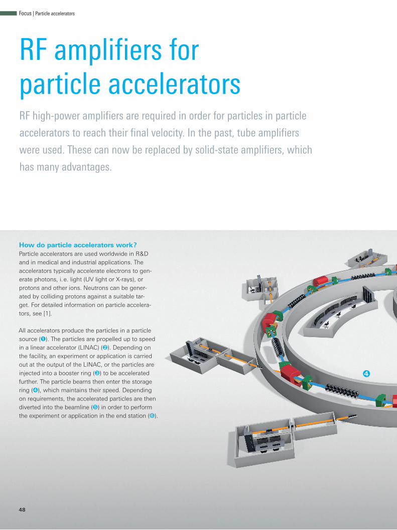
48 RF amplifiers for particle accelerators RF high-power amplifiers are required in order for particles in particle accelerators to reach their final velocity. In the past, tube amplifiers were used. These can now be replaced by solid-state amplifiers, which has many advantages. How do particle accelerators work? Particle accelerators are used worldwide in R&D and in medical and industrial applications. The accelerators typically accelerate electrons to gen- erate photons, i. e. light (UV light or X-rays), or protons and other ions. Neutrons can be gener- ated by colliding protons against a suitable tar- get. For detailed information on particle accelera- tors, see [1]. All accelerators produce the particles in a particle source (Q). The particles are propelled up to speed in a linear accelerator (LINAC) (W). Depending on the facility, an experiment or application is carried out at the output of the LINAC, or the particles are injected into a booster ring (E) to be accelerated further. The particle beams then enter the storage ring (R), which maintains their speed. Depending on requirements, the accelerated particles are then diverted into the beamline (T) in order to perform the experiment or application in the end station (Z). R Focus | Particle accelerators
-
Upload
duongthuan -
Category
Documents
-
view
243 -
download
4
Transcript of RF amplifiers for particle accelerators - Rohde & Schwarz · PDF fileRF amplifiers for...
48
RF amplifiers for particle acceleratorsRF high-power amplifiers are required in order for particles in particle
accelerators to reach their final velocity. In the past, tube amplifiers
were used. These can now be replaced by solid-state amplifiers, which
has many advantages.
How do particle accelerators work?Particle accelerators are used worldwide in R&D and in medical and industrial applications. The accelerators typically accelerate electrons to gen-erate photons, i. e. light (UV light or X-rays), or protons and other ions. Neutrons can be gener-ated by colliding protons against a suitable tar-get. For detailed information on particle accelera-tors, see [1].
All accelerators produce the particles in a particle source (Q). The particles are propelled up to speed in a linear accelerator (LINAC) (W). Depending on the facility, an experiment or application is carried out at the output of the LINAC, or the particles are injected into a booster ring (E) to be accelerated further. The particle beams then enter the storage ring (R), which maintains their speed. Depending on requirements, the accelerated particles are then diverted into the beamline (T) in order to perform the experiment or application in the end station (Z).
R
Focus | Particle accelerators
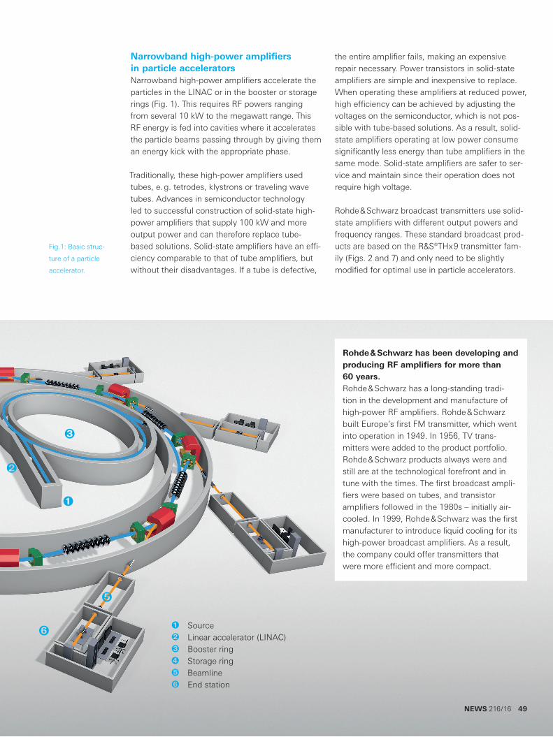
Narrowband high-power amplifiers in particle acceleratorsNarrowband high-power amplifiers accelerate the particles in the LINAC or in the booster or storage rings (Fig. 1). This requires RF powers ranging from several 10 kW to the megawatt range. This RF energy is fed into cavities where it accelerates the particle beams passing through by giving them an energy kick with the appropriate phase.
Traditionally, these high-power amplifiers used tubes, e. g. tetrodes, klystrons or traveling wave tubes. Advances in semiconductor technology led to successful construction of solid-state high-power amplifiers that supply 100 kW and more output power and can therefore replace tube-based solutions. Solid-state amplifiers have an effi-ciency comparable to that of tube amplifiers, but without their disadvantages. If a tube is defective,
the entire amplifier fails, making an expensive repair necessary. Power transistors in solid-state amplifiers are simple and inexpensive to replace. When operating these amplifiers at reduced power, high efficiency can be achieved by adjusting the voltages on the semiconductor, which is not pos-sible with tube-based solutions. As a result, solid-state amplifiers operating at low power consume significantly less energy than tube amplifiers in the same mode. Solid-state amplifiers are safer to ser-vice and maintain since their operation does not require high voltage.
Rohde & Schwarz broadcast transmitters use solid-state amplifiers with different output powers and frequency ranges. These standard broadcast prod-ucts are based on the R&S®THx9 transmitter fam-ily (Figs. 2 and 7) and only need to be slightly modified for optimal use in particle accelerators.
Rohde & Schwarz has been developing and producing RF amplifiers for more than 60 years.Rohde & Schwarz has a long-standing tradi-tion in the development and manufacture of high-power RF amplifiers. Rohde & Schwarz built Europe’s first FM transmitter, which went into operation in 1949. In 1956, TV trans-mitters were added to the product portfolio. Rohde & Schwarz products always were and still are at the technological forefront and in tune with the times. The first broadcast ampli-fiers were based on tubes, and transistor amplifiers followed in the 1980s – initially air-cooled. In 1999, Rohde & Schwarz was the first manufacturer to introduce liquid cooling for its high-power broadcast amplifiers. As a result, the company could offer transmitters that were more efficient and more compact.
Q
W
E
Z
T
Q SourceW Linear accelerator (LINAC)E Booster ringR Storage ringT BeamlineZ End station
Fig.1: Basic struc-
ture of a particle
accelerator.
NEWS 216/16 49
50
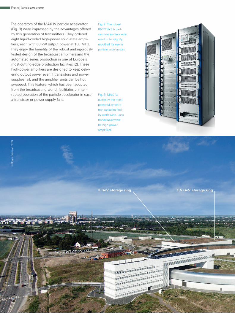
The operators of the MAX IV particle accelerator (Fig. 3) were impressed by the advantages offered by this generation of transmitters. They ordered eight liquid-cooled high-power solid-state ampli-fiers, each with 60 kW output power at 100 MHz. They enjoy the benefits of the robust and rigorously tested design of the broadcast amplifiers and the automated series production in one of Europe’s most cutting-edge production facilities [2]. These high-power amplifiers are designed to keep deliv-ering output power even if transistors and power supplies fail, and the amplifier units can be hot swapped. This feature, which has been adopted from the broadcasting world, facilitates uninter-rupted operation of the particle accelerator in case a transistor or power supply fails.
Fig. 2: The robust
R&S®THx9 broad-
cast transmitters only
need to be slightly
modified for use in
particle accelerators.
Fig. 3: MAX IV,
currently the most
powerful synchro-
tron radiation facil-
ity worldwide, uses
Rohde & Schwarz
RF high-power
amplifiers.
3 GeV storage ring 1.5 GeV storage ring
© R
oger
Erik
sson
/ E
SS
Focus | Particle accelerators
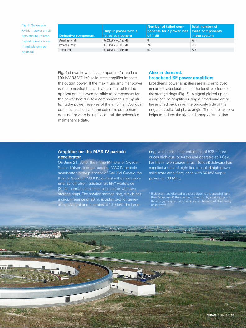
Defective componentOutput power with a failed component
Number of failed com-ponents for a power loss of 1 dB
Total number of these components in the system
Amplifier unit 97.2 kW / –0.120 dB 8 72Power supply 99.1 kW / –0.039 dB 24 216Transistor 99.8 kW / –0.015 dB 63 576
Fig. 4: Solid-state
RF high-power ampli-
fiers ensure uninter-
rupted operation even
if multiple compo-
nents fail.
Fig. 4 shows how little a component failure in a 100 kW R&S®THx9 solid-state amplifier impacts the output power. If the maximum amplifier power is set somewhat higher than is required for the application, it is even possible to compensate for the power loss due to a component failure by uti-lizing the power reserves of the amplifier. Work can continue as usual and the defective component does not have to be replaced until the scheduled maintenance date.
Also in demand: broadband RF power amplifiersBroadband power amplifiers are also employed in particle accelerators – in the feedback loops of the storage rings (Fig. 5). A signal picked up on a ring can be amplified using a broadband ampli-fier and fed back in on the opposite side of the ring at a dedicated phase angle. The feedback loop helps to reduce the size and energy distribution
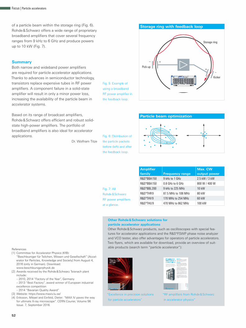
Amplifier for the MAX IV particle acceleratorOn June 21, 2016, the Prime Minister of Sweden, Stefan Löfven, inaugurated the MAX IV particle accelerator in the presence of Carl XVI Gustav, the King of Sweden. MAX IV, currently the most pow-erful synchrotron radiation facility* worldwide [3] [4], consists of a linear accelerator with two storage rings. The smaller storage ring, which has a circumference of 96 m, is optimized for gener-ating UV light and operates at 1.5 GeV. The larger
ring, which has a circumference of 528 m, pro-duces high-quality X-rays and operates at 3 GeV. For these two storage rings, Rohde & Schwarz has supplied a total of eight liquid-cooled high-power solid-state amplifiers, each with 60 kW output power at 100 MHz.
* If electrons are diverted at speeds close to the speed of light, they “counteract” the change of direction by emitting part of the energy as synchrotron radiation in the form of electromag-netic waves.
NEWS 216/16 51
Storage ring with feedback loop
Storage ring
Kicker
Pick-up
– +
+ –
Particle beam optimization
52
of a particle beam within the storage ring (Fig. 6). Rohde & Schwarz offers a wide range of proprietary broadband amplifiers that cover several frequency ranges from 9 kHz to 6 GHz and produce powers up to 10 kW (Fig. 7).
SummaryBoth narrow and wideband power amplifiers are required for particle accelerator applications. Thanks to advances in semiconductor technology, transistors replace expensive tubes in RF power amplifiers. A component failure in a solid-state amplifier will result in only a minor power loss, increasing the availability of the particle beam in accelerator systems.
Based on its range of broadcast amplifiers, Rohde & Schwarz offers efficient and robust solid-state high-power amplifiers. The portfolio of broadband amplifiers is also ideal for accelerator applications.
Dr. Wolfram Titze
Fig. 5: Example of
using a broadband
RF power amplifier in
the feedback loop.
Fig. 6: Distribution of
the particle packets
before (left) and after
the feedback loop.
Fig. 7: All
Rohde & Schwarz
RF power amplifiers
at a glance.
Amplifier family Frequency range
Max. CW output power
R&S®BBA150 9 kHz to 1 GHz 2.5 kW / 3 kW
R&S®BBA150 0.8 GHz to 6 GHz 800 W / 400 W
R&S®BBL200 9 kHz to 225 MHz 10 kW
R&S®THR9 87.5 MHz to 108 MHz 80 kW
R&S®THV9 170 MHz to 254 MHz 60 kW
R&S®THU9 470 MHz to 862 MHz 100 kW
References[1] Committee for Accelerator Physics (KfB):
“Beschleuniger für Teilchen, Wissen und Gesellschaft” [Accel-erator for Particles, Knowledge and Society] from August 4, 2016 (only in German). Download: www.beschleunigerphysik.de
[2] Awards received by the Rohde & Schwarz Teisnach plant include: – 2010, 2014 “Factory of the Year”, Germany – 2013 “Best Factory”, award winner of European industrial excellence competition – 2014 “Bavarian Quality Award”
[3] Website: https://www.maxiv.lu.se/[4] Eriksson, Mikael and Einfeld, Dieter: “MAX IV paves the way
for ultimate X-ray microscope”. CERN Courier, Volume 56 Issue. 7, September 2016.
Other Rohde & Schwarz solutions for particle accelerator applications Other Rohde & Schwarz products, such as oscilloscopes with special fea-tures for accelerator applications and the R&S®FSWP phase noise analyzer and VCO tester, also offer advantages for operators of particle accelerators. Two flyers, which are available for download, provide an overview of suit-able products (search term “particle accelerator”):
“Excellence in precision solutions
for particle accelerators”
“RF amplifiers from Rohde & Schwarz
in accelerator physics”
Focus | Particle accelerators