
Reyrolle Protection Devices · The Solkor, two-ended, line differential relay has been ... as...
14
Energy Management 7SR18 Solkor Line Differential Protection Reyrolle Protection Devices
Transcript of Reyrolle Protection Devices · The Solkor, two-ended, line differential relay has been ... as...

Energy Management
7SR18 SolkorLine Differential Protection
Reyrolle
Protection
Devices

Siemens Protection Devices Limited 2
7SR18 Solkor
Fig. 1. Typical Fascia showing additional LED variant
The Solkor, two-ended, line differential relay has beendeveloped to enhance the Reyrolle family of products.Designed using state-of-the-art hardware technology, itprovides differential protection and control for overheadlines and cable feeders. Housed in a 4U high, size E6case, it provides protection, monitoring, instrumentationand metering with integrated input and output logic, datalogging & fault reports. Communication access to therelay functionality is via a front USB port for local PCconnection or rear RS485 communications port forremote connection.
87L Three-phase differential (two elements)85 Inter-trip Feature50 Instantaneous Overcurrent50G/50N Instantaneous Earth Fault51 Time Delayed Overcurrent51G/51N Time Delayed Measured/Derived/Earth Fault60CTS-I CT Supervision
Two, three-pole differential elements, each with twostage bias characteristics, are provided for differentialprotection. Inter-tripping comes from internal or sixindependent external initiation channels. Overcurrentprotection can operate as a stand-alone feature, it canalso be configured to operate as ‘guard’ feature and/orback-up in case of protection signalling communicationsfailure. Connection to CTs is via selectable 1 A or 5 Ainputs. Ratio correction for miss-matched line currenttransformer ratios is available. The ability to invert CTinputs is provided to facilitate commissioning. There are
five or eight user-programmable binary output contactsand three or six user programmable status inputs withpick-up and drop-off timers.
Local end and remote end ammeters,Differential starters,Protection signalling link status,General alarms,Binary Input / Output status,Trip circuit supervisionTime and dateStartersFault recordsEvent recordsCircuit breaker trip countersI2t summation for contact wearCommunication loop-back test modes.Communication link supervision.Time and DateStartersPower on counter
Sequence of event recordsUp to 1000 events are stored and time tagged to 1 msresolution.
Fault RecordsThe last 10 fault records are displayed on the relay fasciaand are also available through the communicationinterface, with time and date of trip, measured quantitiesand type of fault.
Waveform recorderThe waveform recorder stores analogue data for all polesand the states of protection functions, binary inputs, LEDsand binary outputs with user settable pre & post triggerdata. A record can be triggered from protection function,binary input or via data communications. The 8 mostrecent records are stored and made available forconvenient retrieval using Reydisp Evolution.
Demand Metering
A record of demand is available. The demand minimum,maximum and average values for currents, voltages,power and frequency, over a user selectable period oftime, is displayed and can be downloaded. Typically this isset as a rolling value for the last 24 hours.
Real Time Clock
The time and date can be set and are maintainedwhile the relay is de-energised by a back up storagecapacitor. The time can be synchronized from a binaryinput pulse or the data communication channel.
Data Acquisition -Via Communication Interface
Monitoring Functions
Function Overview
Description
Siemens Protection Devices Limited 3
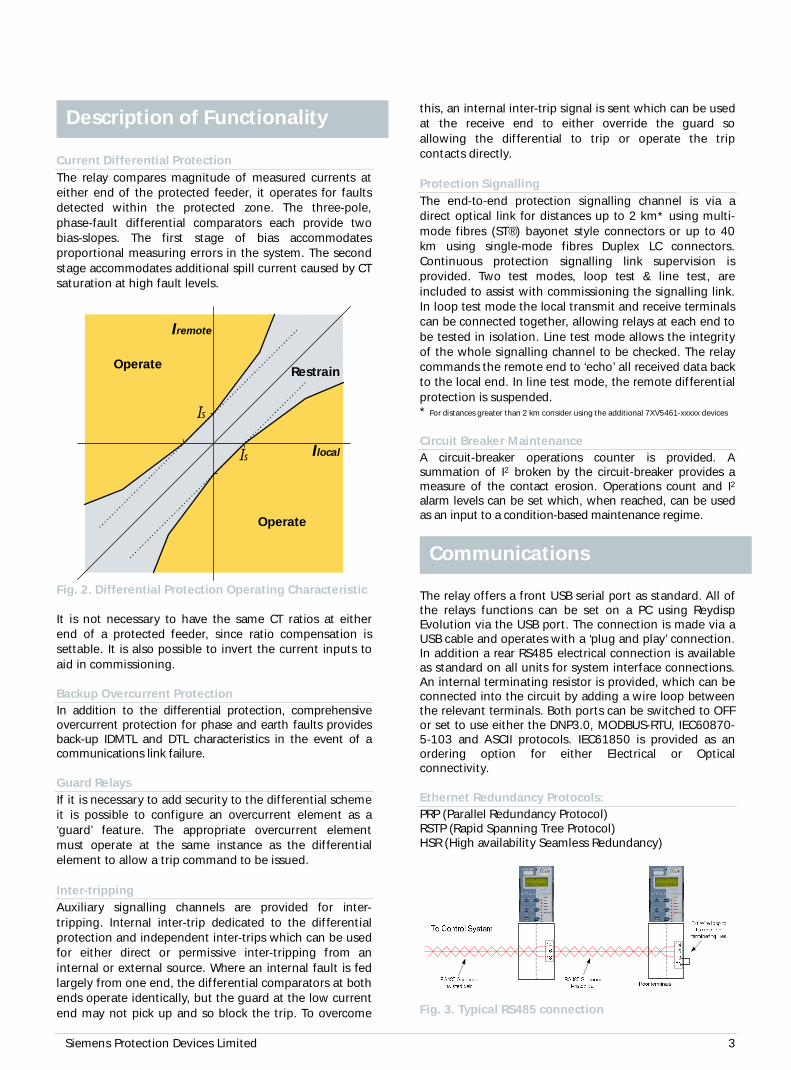
Current Differential ProtectionThe relay compares magnitude of measured currents ateither end of the protected feeder, it operates for faultsdetected within the protected zone. The three-pole,phase-fault differential comparators each provide twobias-slopes. The first stage of bias accommodatesproportional measuring errors in the system. The secondstage accommodates additional spill current caused by CTsaturation at high fault levels.
Restrain
Operate
Is
Iremote
Ilocal
Is
Operate
Fig. 2. Differential Protection Operating Characteristic
It is not necessary to have the same CT ratios at eitherend of a protected feeder, since ratio compensation issettable. It is also possible to invert the current inputs toaid in commissioning.
Backup Overcurrent ProtectionIn addition to the differential protection, comprehensiveovercurrent protection for phase and earth faults providesback-up IDMTL and DTL characteristics in the event of acommunications link failure.
Guard RelaysIf it is necessary to add security to the differential schemeit is possible to configure an overcurrent element as a‘guard’ feature. The appropriate overcurrent elementmust operate at the same instance as the differentialelement to allow a trip command to be issued.
Inter-trippingAuxiliary signalling channels are provided for inter-tripping. Internal inter-trip dedicated to the differentialprotection and independent inter-trips which can be usedfor either direct or permissive inter-tripping from aninternal or external source. Where an internal fault is fedlargely from one end, the differential comparators at bothends operate identically, but the guard at the low currentend may not pick up and so block the trip. To overcome
this, an internal inter-trip signal is sent which can be usedat the receive end to either override the guard soallowing the differential to trip or operate the tripcontacts directly.
Protection SignallingThe end-to-end protection signalling channel is via adirect optical link for distances up to 2 km* using multi-mode fibres (ST®) bayonet style connectors or up to 40km using single-mode fibres Duplex LC connectors.Continuous protection signalling link supervision isprovided. Two test modes, loop test & line test, areincluded to assist with commissioning the signalling link.In loop test mode the local transmit and receive terminalscan be connected together, allowing relays at each end tobe tested in isolation. Line test mode allows the integrityof the whole signalling channel to be checked. The relaycommands the remote end to ‘echo’ all received data backto the local end. In line test mode, the remote differentialprotection is suspended.* For distances greater than 2 km consider using the additional 7XV5461-xxxxx devices
Circuit Breaker MaintenanceA circuit-breaker operations counter is provided. Asummation of I2 broken by the circuit-breaker provides ameasure of the contact erosion. Operations count and I2
alarm levels can be set which, when reached, can be usedas an input to a condition-based maintenance regime.
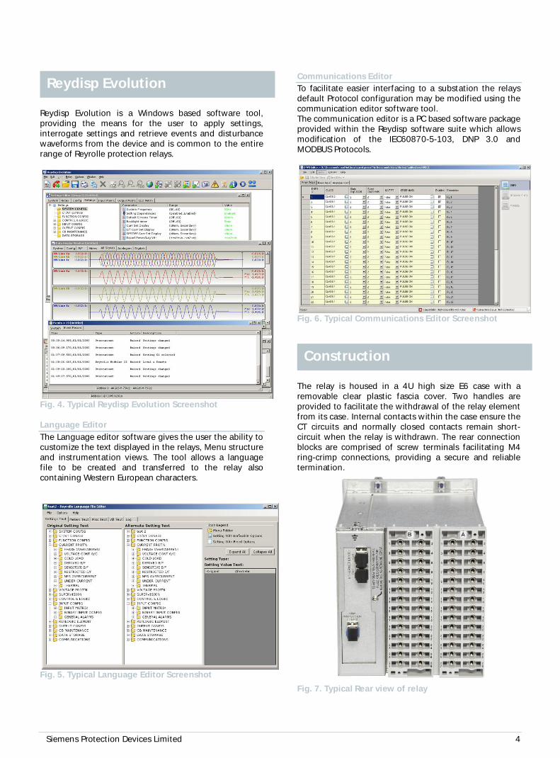
The relay offers a front USB serial port as standard. All ofthe relays functions can be set on a PC using ReydispEvolution via the USB port. The connection is made via aUSB cable and operates with a ‘plug and play’ connection.In addition a rear RS485 electrical connection is availableas standard on all units for system interface connections.An internal terminating resistor is provided, which can beconnected into the circuit by adding a wire loop betweenthe relevant terminals. Both ports can be switched to OFFor set to use either the DNP3.0, MODBUS-RTU, IEC60870-5-103 and ASCII protocols. IEC61850 is provided as anordering option for either Electrical or Opticalconnectivity.
Ethernet Redundancy Protocols:PRP (Parallel Redundancy Protocol)RSTP (Rapid Spanning Tree Protocol)HSR (High availability Seamless Redundancy)
Fig. 3. Typical RS485 connection
Communications
Description of Functionality
Siemens Protection Devices Limited 4
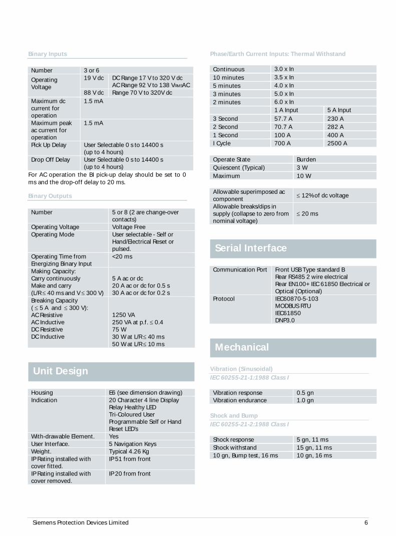
Reydisp Evolution is a Windows based software tool,providing the means for the user to apply settings,interrogate settings and retrieve events and disturbancewaveforms from the device and is common to the entirerange of Reyrolle protection relays.
Fig. 4. Typical Reydisp Evolution Screenshot
Language EditorThe Language editor software gives the user the ability tocustomize the text displayed in the relays, Menu structureand instrumentation views. The tool allows a languagefile to be created and transferred to the relay alsocontaining Western European characters.
Fig. 5. Typical Language Editor Screenshot
Communications EditorTo facilitate easier interfacing to a substation the relaysdefault Protocol configuration may be modified using thecommunication editor software tool.The communication editor is a PC based software packageprovided within the Reydisp software suite which allowsmodification of the IEC60870-5-103, DNP 3.0 andMODBUS Protocols.
Fig. 6. Typical Communications Editor Screenshot
The relay is housed in a 4U high size E6 case with aremovable clear plastic fascia cover. Two handles areprovided to facilitate the withdrawal of the relay elementfrom its case. Internal contacts within the case ensure theCT circuits and normally closed contacts remain short-circuit when the relay is withdrawn. The rear connectionblocks are comprised of screw terminals facilitating M4ring-crimp connections, providing a secure and reliabletermination.
Fig. 7. Typical Rear view of relay
Construction
Reydisp Evolution

Siemens Protection Devices Limited 5
Fig. 8. Typical User Interface
The operator interface is designed to provide a userfriendly method of controlling, viewing menus, enteringsettings and retrieving data from the relay. Five buttonsare provided for navigation around the menu structure.
LCDA 4 line by 20 character liquid crystal display (LCD) withpower save operation permits viewing of the relayidentifier, settings, instrumentation, fault data andcontrol commands. Up to 6 user programmable generalalarms can be configured for status indication.
LEDsA steadily illuminated LED indicates the ‘ProtectionHealthy’ condition. There are 9 or 17 user programmableLEDs available eliminating the need for additionalexpensive panel mounted indication and associatedwiring. Each is tri-coloured (red, green, yellow) allowingfor indication severity classification of the associatedfunction’s state and has a label insert for textidentification.
Relay InformationThe device type and rating information is shown asstandard on the fascia slip-in label. There is also provisionfor relay designation to be displayed on the LCD showing‘Relay Identifier’ & ‘Circuit Identifier’ information. Inaddition space is provided on the fascia via a slip-in labelrepeating such information.
For full technical data refer to the PerformanceSpecification Section of the Technical Manual.
Current Inputs
Quantity 3 x Phase & 1 x EarthRated Current In 1 A or 5 AMeasuring Range 80 x InInstrumentation ≥ 0.1xIn ±1% InFrequency 50 Hz or 60 HzThermal Withstand:Continuous10 Minutes2 Minutes1 Second1 Cycle
3 x In3.5 x In6 x In100 A (1 A) 350 A (5 A)700 A (1 A) 2500 A (5 A)
Burden @ In ≤0.02 VA (1 A phase and Earthelement)≤0.2 VA (5 A phase and earthelement)
Auxiliary Supply
Rated DC Voltage Nominal Range 24 V to 250VAbsolute Range 19.2 V to 275 V
Allowablesuperimposed accomponent
12% of DC voltage
Rated AC Voltage Nominal Range 100 V to 230 V AC50 Hz or 60 HzAbsolute Range 88 V to 253 V rms AC
PowerConsumption:
Min (DC)Max (DC)
3.9 W8 W
Min (AC)Max (AC)
9 VA 0.5 PF15 VA 0.5 PF
Allowablebreaks/dips insupply (collapse tozero)
DC 50 msAC 2.5 cycles or
3 cycles @50 Hz or60 Hz
Inputs and Outputs
Technical DataUser Interface
Siemens Protection Devices Limited 6
Binary Inputs
Number 3 or 6
OperatingVoltage
19 V dc DC Range 17 V to 320 V dcAC Range 92 V to 138 VRMSAC
88 V dc Range 70 V to 320V dcMaximum dccurrent foroperation
1.5 mA
Maximum peakac current foroperation
1.5 mA
Pick Up Delay User Selectable 0 s to 14400 s(up to 4 hours)
Drop Off Delay User Selectable 0 s to 14400 s(up to 4 hours)
For AC operation the BI pick-up delay should be set to 0ms and the drop-off delay to 20 ms.
Binary Outputs
Number 5 or 8 (2 are change-overcontacts)
Operating Voltage Voltage FreeOperating Mode User selectable - Self or
Hand/Electrical Reset orpulsed.
Operating Time fromEnergizing Binary Input
<20 ms
Making Capacity:Carry continuouslyMake and carry(L/R £ 40 ms and V £ 300 V)
5 A ac or dc20 A ac or dc for 0.5 s30 A ac or dc for 0.2 s
Breaking Capacity( £ 5 A and £ 300 V):AC ResistiveAC InductiveDC ResistiveDC Inductive
1250 VA250 VA at p.f. £ 0.475 W30 W at L/R £ 40 ms50 W at L/R £ 10 ms
Housing E6 (see dimension drawing)Indication 20 Character 4 line Display
Relay Healthy LEDTri-Coloured UserProgrammable Self or HandReset LED’s
With-drawable Element. YesUser Interface. 5 Navigation KeysWeight. Typical 4.26 KgIP Rating installed withcover fitted.
IP 51 from front
IP Rating installed withcover removed.
IP 20 from front
Phase/Earth Current Inputs: Thermal Withstand
Continuous 3.0 x In
10 minutes 3.5 x In5 minutes 4.0 x In
3 minutes 5.0 x In2 minutes 6.0 x In
1 A Input 5 A Input
3 Second 57.7 A 230 A2 Second 70.7 A 282 A1 Second 100 A 400 AI Cycle 700 A 2500 A
Operate State BurdenQuiescent (Typical) 3 WMaximum 10 W
Allowable superimposed accomponent
£ 12% of dc voltage
Allowable breaks/dips insupply (collapse to zero fromnominal voltage)
£ 20 ms
Communication Port Front USB Type standard BRear RS485 2 wire electricalRear EN100+ IEC 61850 Electrical orOptical (Optional)
Protocol IEC60870-5-103MODBUS RTUIEC61850DNP3.0
Vibration (Sinusoidal)IEC 60255-21-1:1988 Class I
Vibration response 0.5 gnVibration endurance 1.0 gn
Shock and BumpIEC 60255-21-2:1988 Class I
Shock response 5 gn, 11 msShock withstand 15 gn, 11 ms10 gn, Bump test, 16 ms 10 gn, 16 ms
Mechanical
Serial Interface
Unit Design
Siemens Protection Devices Limited 7
SeismicIEC 60255-21-3 Class I
Seismic Response 1 gn
Mechanical Classification
Durability In excess of 106 operations
InsulationIEC 60255-27
Between all terminals andearth for 1 minute
2.5 kV rms
Between independentcircuits for 1 minute
2.5 kV rms
Across normally opencontacts for 1 minute
1.0 kV rms
Transient overvoltageIEC 60255-27
Between all the terminalsand earth or between anytwo independent circuitswithout damage orflashover
5 kV1.2/50 µs0.5 J
Slow Damped Oscillatory WaveIEC 60255-26
2.5 kV Common mode < 3 % deviation1.0 kV Differential mode
Electrostatic DischargeIEC 60255-26
8 kV, Contact discharge £ 5 % variation
Radiated Radio Frequency Electromagnetic Field Im-munityIEC60255-26
10 V/m, 80 MHz to 1000 MHz (Sweep) £ 5 % variation10 V/m, 1.4 GHz to 2.7 GHz (Sweep) £ 5 % variation10 V/m, 80 MHz, 160 MHz, 380 MHz, 450MHz, 900 MHz, 1850 MHz, 2150 MHz (Spot)
£ 5 % variation
Fast TransientIEC 60255-26
4 kV, 5/50 ns, 5 kHz, repetitive £ 3 % variation* Note 20 ms drop-off delay applied to binary inputs
Conducted Disturbance Induced by Radio FrequencyInterferenceIEC 60255-26
10 V, 0.15 MHz to 80 MHz £ 5 % variation
Conducted Disturbance Induced by Radio FrequencyInterference LimitsIEC 60255-26
Frequency Range Limits dB(µV)Quasi-peak Average
0.15 MHz to 0.5 MHz 79 660.5 MHz to 30 MHz 73 60
Radiated Radio Frequency Electromagnetic Field Im-munity LimitsIEC 60255-26
Frequency RangeLimits at 10 mQuasi-peak, dB(µV/m)
30 to 230 MHz 40230 to 1000 MHz 47
SurgeIEC 60255-26
Type Level Variation
Analogue Inputs,Auxiliary Power:Line to Earth
4.0 kV £ 10%
I/O:
Line to Earth2.0 kV * £ 10%
RS485 Comms port:Line to Earth
1.0 kV No Data Loss
Analogue Inputs,Auxiliary Power:Line to Line
2.0 kV £ 10%
I/O:Line to Line
1.0 kV * £ 10%
* Note 50 ms pick-up delay and 20 ms drop-off delay applied to binary inputs
TemperatureIEC 60068-2-1
Operating range -10 °C to +55 °CStorage range -25 °C to +70 °C
HumidityIEC 60068-2-78
Operational test 56 days at +40 °C and 93 % RH
Environmental
Electrical Tests

Siemens Protection Devices Limited 8
General Accuracy
Reference ConditionsGeneral IEC 60255-151Current settings 100% of InCurrent input IDMTL – 0.05 to 2.5 xIs
DTL – 0.05 to 50 xIsAuxiliary supply NominalFrequency 50 Hz or 60 HzAmbient temperature 20 °C
General SettingsTransient overreach ofhighset/lowset (X/R = 100)
£ 5 %
Disengaging time (see note) < 42 msOvershoot time < 40 ms
Note. Output contacts have a programmable minimumdwell time, after which the disengaging time is as above.
Accuracy Influencing Factors
Temperature-10 °C to +55 °C £ 5 % variationFrequency47 Hz to 52 Hz57 Hz to 62 Hz
Level: £ 5 % variation
Operatingtime:
£ 5 % variation
Harmonic contentFrequencies to 550Hz
£ 5 % variation
Current differential
LevelNo. of elements 2Initial Setting 0.1 to 2.51st Bias Slope 0.1 to 0.72nd Bias Slope 0.5 to 2
Typical operating threshold characteristics are shownbelow: -
Fig. 9 Differential Protection Operating Characteristic
Protection Elements
Siemens Protection Devices Limited 9
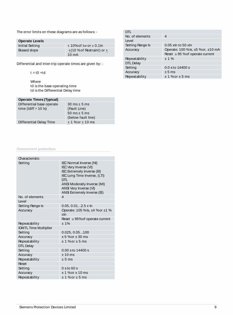
The error limits on these diagrams are as follows: -
Operate LevelsInitial Setting ± 10% of IOP or ± 0.1InBiased slope +(10 % of Restraint) or +
10 mA
Differential and Inter-trip operate times are given by: -
t = t0 +td
Wheret0 is the base operating timetd is the Differential Delay time
Operate Times (Typical)Differential base operatetime (ldiff > 10 ls)
30 ms ± 5 ms(Fault Line)50 ms ± 5 ms(below fault line)
Differential Delay Time + 1 % or + 10 ms
Overcurrent protection
CharacteristicSetting IEC Normal Inverse (NI)
IEC Very Inverse (VI)IEC Extremely Inverse (EI)IEC Long Time Inverse, (LTI)DTLANSI Moderatly Inverse (MI)ANSI Very Inverse (VI)ANSI Extremely Inverse (EI)
No. of elements 4LevelSetting Range Is 0.05, 0.01…2.5 x InAccuracy Operate: 105 % Is, ±4 % or ±1 %
xInReset ≥ 95% of operate current
Repeatability ± 1%IDMTL Time MultiplierSetting 0.025, 0.05…100Accuracy ± 5 % or ± 30 msRepeatability ± 1 % or ± 5 msDTL DelaySetting 0.00 s to 14400 sAccuracy ± 10 msRepeatability ± 5 msResetSetting 0 s to 60 sAccuracy ± 1 % or ± 10 msRepeatability ± 1 % or ± 5 ms
DTLNo. of elements 4LevelSetting Range Is 0.05 xIn to 50 xInAccuracy Operate: 100 % Is, ±5 % or, ±10 mA
Reset ≥ 95 % of operate currentRepeatability ± 1 %DTL DelaySetting 0.0 s to 14400 sAccuracy ± 5 msRepeatability ± 1 % or ± 5 ms

Siemens Protection Devices Limited 10
RS4
85
Fig. 10. Connections Diagram for 7SR18 Non-Directional Relay (3BI and 5BO)
Connection Diagrams
Siemens Protection Devices Limited 11
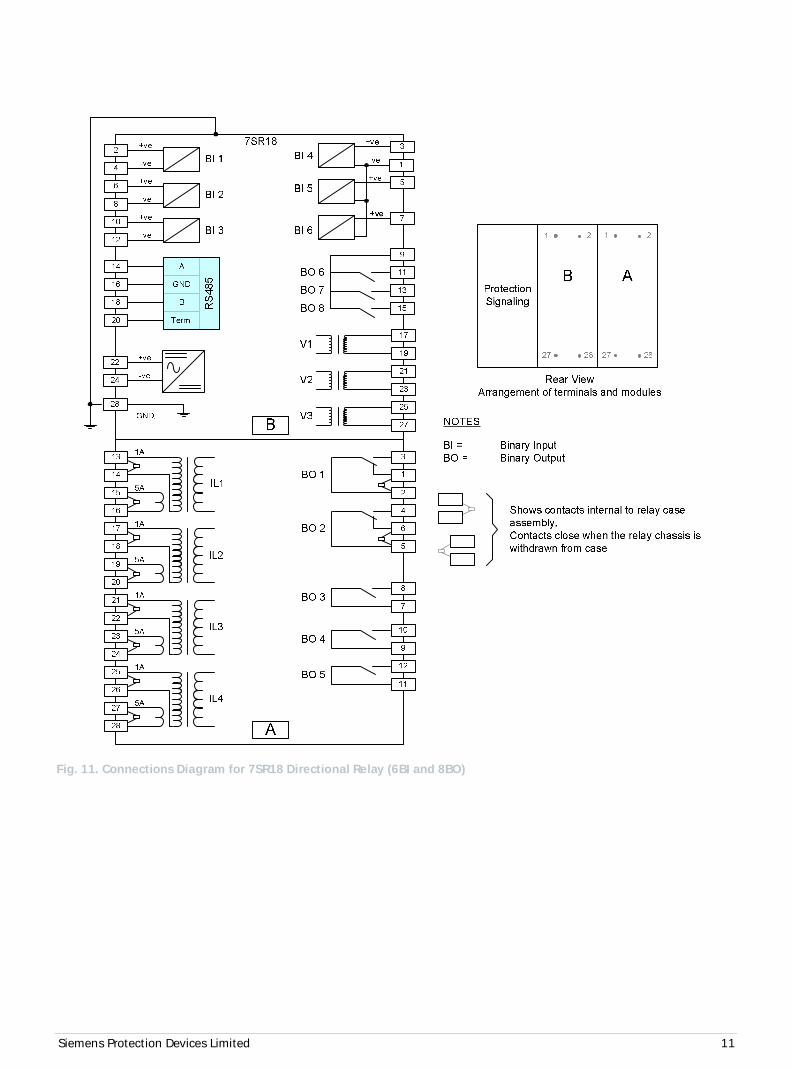
Fig. 11. Connections Diagram for 7SR18 Directional Relay (6BI and 8BO)
Siemens Protection Devices Limited 12
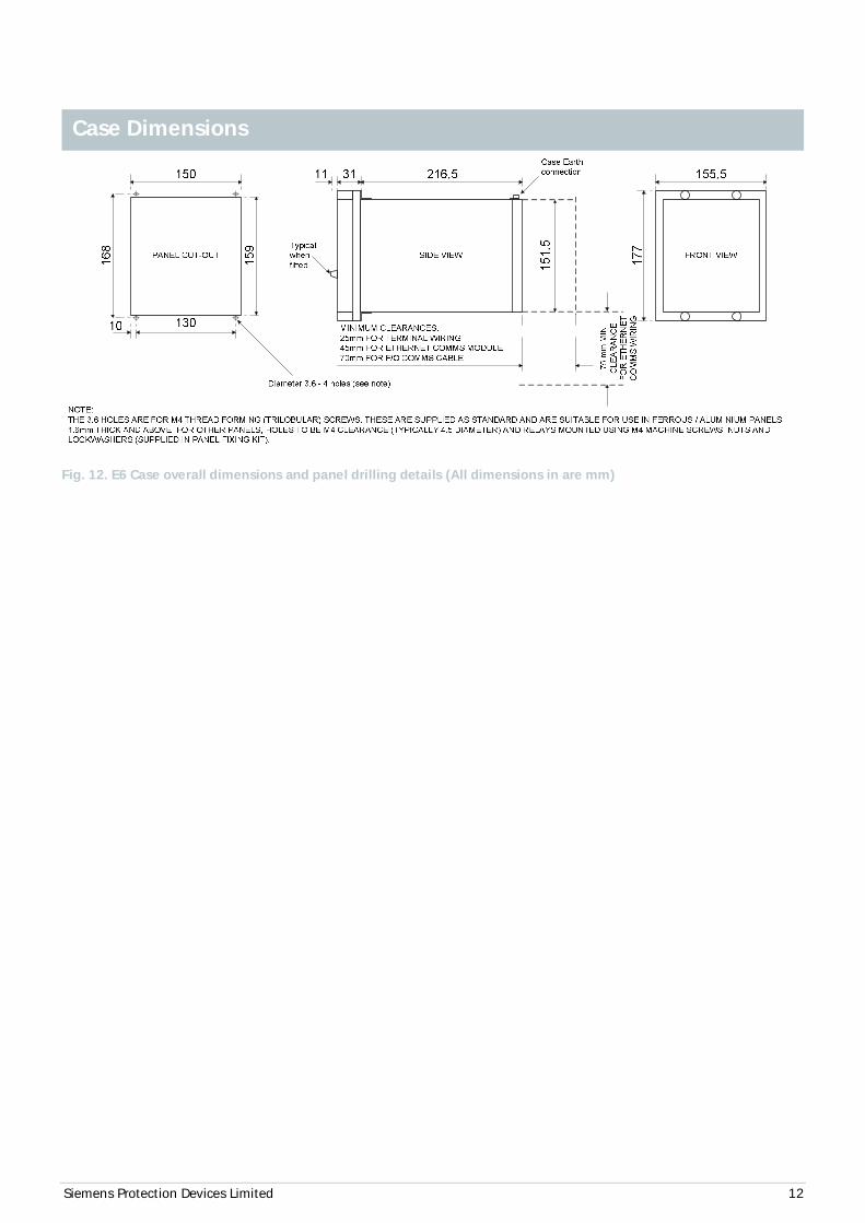
Fig. 12. E6 Case overall dimensions and panel drilling details (All dimensions in are mm)
Case Dimensions
Siemens Protection Devices Limited 13
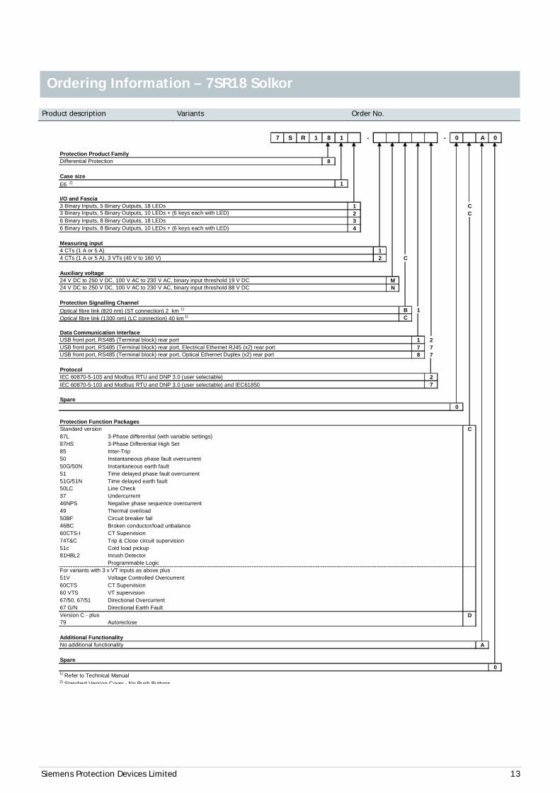
Product description Variants Order No.
7 S R 1 8 1 - - 0 A 0
Protection Product FamilyDifferential Protection 8
Case sizeE6 2) 1
I/O and Fascia3 Binary Inputs, 5 Binary Outputs, 18 LEDs 1 C
2 C6 Binary Inputs, 8 Binary Outputs, 18 LEDs 36 Binary Inputs, 8 Binary Outputs, 10 LEDs + (6 keys each with LED) 4
Measuring input4 CTs (1 A or 5 A) 14 CTs (1 A or 5 A), 3 VTs (40 V to 160 V) 2 C
Auxiliary voltage24 V DC to 250 V DC, 100 V AC to 230 V AC, binary input threshold 19 V DC M24 V DC to 250 V DC, 100 V AC to 230 V AC, binary input threshold 88 V DC N
Protection Signalling ChannelOptical fibre link (820 nm) (ST connection) 2 km 1) B 1Optical fibre link (1300 nm) (LC connection) 40 km 1) C
Data Communication InterfaceUSB front port, RS485 (Terminal block) rear port 1 2USB front port, RS485 (Terminal block) rear port, Electrical Ethernet RJ45 (x2) rear port 7 7USB front port, RS485 (Terminal block) rear port, Optical Ethernet Duplex (x2) rear port 8 7
ProtocolIEC 60870-5-103 and Modbus RTU and DNP 3.0 (user selectable) 2IEC 60870-5-103 and Modbus RTU and DNP 3.0 (user selectable) and IEC61850 7
Spare0
Protection Function PackagesStandard version C87L 3-Phase differential (with variable settings)87HS 3-Phase Differential High Set85 Inter-Trip50 Instantaneous phase fault overcurrent50G/50N Instantaneous earth fault51 Time delayed phase fault overcurrent51G/51N Time delayed earth fault50LC Line Check37 Undercurrent46NPS Negative phase sequence overcurrent49 Thermal overload50BF Circuit breaker fail46BC Broken conductor/load unbalance60CTS-I CT Supervision74T&C Trip & Close circuit supervision51c Cold load pickup81HBL2 Inrush Detector
Programmable LogicFor variants with 3 x VT inputs as above plus51V Voltage Controlled Overcurrent60CTS CT Supervision60 VTS VT supervision67/50, 67/51 Directional Overcurrent67 G/N Directional Earth FaultVersion C - plus D79 Autoreclose
Additional FunctionalityNo additional functionality A
Spare0
3 Binary Inputs, 5 Binary Outputs, 10 LEDs + (6 keys each with LED)
1) Refer to Technical Manual2) Standard Version Cover - No Push Buttons
Ordering Information – 7SR18 Solkor
Siemens Protection Devices Limited 14
www. siemens.com/Reyrolle
Published by and copyright © 2016:Siemens Protection Devices LimitedP.O. Box 8North Farm RoadHebburnTyne & WearNE31 1TZUnited KingdomPhone: +44 (0)191 401 7901Fax: +44 (0)191 401 5575E-mail: [email protected]
EMDG-C10087-00-76GB
December 2016
For enquires please contact our Customer Support CenterPhone: +49 180/524 8437 (24hrs)Fax: +49 180/524 24 71E-mail: [email protected]/protection
Subject to change without notice,. Printed in the UK.


![7pg21 Solkor r Rf Catalogue Sheet[1]](https://static.fdocuments.in/doc/165x107/547ad5beb379594e2b8b4b82/7pg21-solkor-r-rf-catalogue-sheet1.jpg)

